EP2211139A1 - Automated sensor specific calibration through sensor parameter download - Google Patents
Automated sensor specific calibration through sensor parameter download Download PDFInfo
- Publication number
- EP2211139A1 EP2211139A1 EP10151311A EP10151311A EP2211139A1 EP 2211139 A1 EP2211139 A1 EP 2211139A1 EP 10151311 A EP10151311 A EP 10151311A EP 10151311 A EP10151311 A EP 10151311A EP 2211139 A1 EP2211139 A1 EP 2211139A1
- Authority
- EP
- European Patent Office
- Prior art keywords
- sensor
- clearance
- memory
- calibration data
- sensor information
- Prior art date
- Legal status (The legal status is an assumption and is not a legal conclusion. Google has not performed a legal analysis and makes no representation as to the accuracy of the status listed.)
- Granted
Links
Images


Classifications
-
- G—PHYSICS
- G01—MEASURING; TESTING
- G01B—MEASURING LENGTH, THICKNESS OR SIMILAR LINEAR DIMENSIONS; MEASURING ANGLES; MEASURING AREAS; MEASURING IRREGULARITIES OF SURFACES OR CONTOURS
- G01B7/00—Measuring arrangements characterised by the use of electric or magnetic techniques
- G01B7/14—Measuring arrangements characterised by the use of electric or magnetic techniques for measuring distance or clearance between spaced objects or spaced apertures
-
- F—MECHANICAL ENGINEERING; LIGHTING; HEATING; WEAPONS; BLASTING
- F01—MACHINES OR ENGINES IN GENERAL; ENGINE PLANTS IN GENERAL; STEAM ENGINES
- F01D—NON-POSITIVE DISPLACEMENT MACHINES OR ENGINES, e.g. STEAM TURBINES
- F01D11/00—Preventing or minimising internal leakage of working-fluid, e.g. between stages
- F01D11/08—Preventing or minimising internal leakage of working-fluid, e.g. between stages for sealing space between rotor blade tips and stator
- F01D11/14—Adjusting or regulating tip-clearance, i.e. distance between rotor-blade tips and stator casing
-
- F—MECHANICAL ENGINEERING; LIGHTING; HEATING; WEAPONS; BLASTING
- F01—MACHINES OR ENGINES IN GENERAL; ENGINE PLANTS IN GENERAL; STEAM ENGINES
- F01D—NON-POSITIVE DISPLACEMENT MACHINES OR ENGINES, e.g. STEAM TURBINES
- F01D21/00—Shutting-down of machines or engines, e.g. in emergency; Regulating, controlling, or safety means not otherwise provided for
- F01D21/003—Arrangements for testing or measuring
-
- F—MECHANICAL ENGINEERING; LIGHTING; HEATING; WEAPONS; BLASTING
- F01—MACHINES OR ENGINES IN GENERAL; ENGINE PLANTS IN GENERAL; STEAM ENGINES
- F01D—NON-POSITIVE DISPLACEMENT MACHINES OR ENGINES, e.g. STEAM TURBINES
- F01D21/00—Shutting-down of machines or engines, e.g. in emergency; Regulating, controlling, or safety means not otherwise provided for
- F01D21/04—Shutting-down of machines or engines, e.g. in emergency; Regulating, controlling, or safety means not otherwise provided for responsive to undesired position of rotor relative to stator or to breaking-off of a part of the rotor, e.g. indicating such position
Definitions
- the present description relates generally to a method and a system for automatic download of calibration data of a sensor into electronics interface of a sensor system, and more specifically to conveying physical sensor parameters to the electronics interface.
- sensor systems are used to measure various parameters.
- such sensor systems are used in various applications.
- the sensor systems are used in various applications.
- the sensor systems are used in various applications.
- the sensor systems are used in various applications.
- the sensor systems are used in various applications.
- the sensor systems are used in various applications.
- the sensor systems are used in various applications.
- the sensor systems are used in various applications.
- the sensor systems are used in various applications.
- the sensor systems are used to measure a clearance between a static shroud and turbine blades.
- Such sensor systems typically include sensors and electronics interface.
- the sensor output may not provide the signal indicative of a parameter to be measured.
- the electronics interface is configured to convert the sensor output signal to a signal representative of the parameter to be measured or in other words to provide a calibrated result. The conversion from the sensor output signal to the signal representative of the parameter to be measured is based on the sensor characteristics or calibration data of the sensor.
- New installations of sensors in the sensor system cause sensor variations. This results in significant error in the measurement if the electronics interface is not calibrated accordingly.
- Sensor variations include manufacturing variations or performance variations. In general, a very tight constraint on manufacturing is required to obtain calibrated results across manufactured sensors.
- Various methods have been utilized to obtain the calibrated result in presence of sensor variations.
- One such method is manual calibration of the electronics interface.
- the manual calibration procedure significantly increases the installation time of the new sensor. It further requires a higher training level for the personnel required for the sensor installation.
- Another method is to install a new electronics interface along with the new sensor installation. The new electronics interface is coupled to the new sensor and is calibrated with the calibration data of that sensor.
- replacing both the sensor and the electronics interface reduces the flexibility of inventory management and reduces the overall life of the system to that of the shortest life component.
- the sensor performance may be a function of the combination of the sensor element, cabling and electronics. Requiring that the three components be replaced at the same time poses difficulty in installation. It the case of aircraft engine installations for example, it is desirable to maintain the cabling even if the sensor element or electronics need to be replaced. This avoids costly and time consuming wire routing.
- a sensor system in accordance with one exemplary embodiment of the present invention, includes a clearance sensor for measuring a clearance parameter between a stationary component and a rotating component of a rotating machine and to output a clearance measurement signal.
- the system also includes a sensor memory attached to the sensor.
- a first sensor information is stored in the sensor memory.
- the system further includes a electronics interface memory for storing a second sensor information and an electronics interface, which reads the first and the second sensor information and matches the clearance sensor with a respective plurality of calibration data based on the first and the second sensor information.
- a method for calibrating a clearance sensor includes storing a first sensor information in a clearance sensor memory.
- the method also includes storing a second sensor information in a electronics interface memory and reading the first sensor information from the clearance sensor memory.
- the method further includes calibrating the clearance sensor based on the first sensor information and the second sensor information.
- a calibrated sensor includes a sensor element and a memory coupled to the sensor element. A plurality of sensor specific information is stored in the memory.
- embodiments of the invention include a system and a method for self-calibration of clearance measurement system.
- clearance measurement systems it is applicable to any measurement system, such as a temperature measurement system or a pressure measurement system.
- FIG. 1 is a perspective view of an exemplary rotating machine, such as an aircraft engine turbine 10, wherein aspects of the present technique can be incorporated. It should be noted here, however, that the present technique can be used in any other rotating machine such as but not limited to steam turbine and gas turbine.
- the turbine includes a rotor 12 mounted on a shaft 14.
- a plurality of turbine blades 16, are affixed to the rotor 12.
- the blades 16 are subject to a fluid 18 or steam at a high temperature and pressure, which does work on the blades 16 and causes them to rotate about an axis 20.
- the blades 16 rotate within a stationary housing or shroud 22 that is positioned approximately radially and circumferentially around the blades.
- one or more clearance sensors 24 are disposed within and circumferentially around the stationary shroud 22.
- the clearance sensors 24 include capacitive probes. Capacitive probe sensors provide variable capacitance as a representation of the clearance.
- the clearance sensors 24 may include microwave based sensors, optical sensors, or eddy current sensors. Each of the sensors 24 is configured to generate a signal indicative of a radial and/or an axial position of the blades 16 with respect to the shroud 22 at their respective circumferential locations.
- the sensor signals 26 are transmitted to a clearance measurement system 28 for measuring the clearance. Further, the clearance measurement through the clearance measurement system 28 is used for controlling the clearance between the shroud 22 and the turbine blades 16 via a clearance control system 30.
- Fig. 2 illustrates an exemplary configuration of a clearance measurement system 28 of Fig. 1 .
- the system 28 in this embodiment comprises first and second sensors 40, 42 configured to generate first and second measurement signals representative of first and second capacitance values between the shroud 22 and the rotor blades 16 of steam turbine of Fig. 1 .
- the clearance 32 between the shroud and the rotor blades of the turbine is calculated by ratiometric techniques from first and second signals of first and second sensors 40, 42.
- a bidirectional coupler 44 and a phase detector 46 are coupled to the first sensor 40 for measuring the capacitance through the first sensor 40.
- a bidirectional coupler 48 and a phase detector 50 are coupled to the second sensor 42 for measuring the capacitance through the second sensor 42.
- a signal generator 52 is coupled to the first and second sensors 40 and 42 for exciting the first and second sensors.
- first and second amplifiers 54, 56 are coupled to the signal generator 52 to amplify input signals generated from the signal generator 52.
- the amplifiers 54, 56 are optional depending upon the signal generation capability and filtering can also be used to condition the signal generator output.
- a capacitor (not shown) can be deployed in series with each sensors 40, 42 and signal generator 52 and the phase detectors 46, 52 can be coupled on either side of the capacitor.
- the signal generator 52 at an excitation frequency excites first and second sensors 40, 42 via the first and second excitation signals 62, 64.
- a first and second reflected signal 58, 60 corresponding to the first and second excited signal 62, 64 will originate from the first and second sensors 40, 42.
- the capacitance through the first sensor 40 is measured by measuring a phase difference between the excitation signal 62 and the corresponding reflected signal 58 by the bidirectional coupler 44 and the phase detector 46.
- the phase detector 46 is configured to detect a first reflected signal 58 based upon the excitation frequency to generate first measurement signal 66.
- measuring a phase difference between the excitation signal 64 and the corresponding reflected signal 60 by the bidirectional coupler 48 and the phase detector 50 generates the second measurement signal 68 representative of the capacitance through the second sensor 42.
- the first and second measurement signals 66 and 68 are then transmitted to a calibration circuitry 70 for calculation of the clearance based upon a function of the first and second measurement signals 66 and 68. In one embodiment the function is a ratio between first and second measurement signals.
- the calibration circuitry 70 further communicates with sensors 40, 42 to detect variations in sensor parameters.
- the sensor system 28 in this example employs two sensors 40, 42 for capacitive measurements between the rotor blades 22 and the shroud 16.
- other configurations of the sensor system having more sensors are within the scope of the system.
- FIG. 3 shows a calibration system 90 of the rotating machine of FIG. 1 .
- a first memory 98 is attached to the clearance sensor 96.
- the first memory 98 is configured to store sensor specific information.
- the sensor specific information is a sensor identification number.
- the specific information may be sensor geometry information.
- the sensor geometry & tolerance are specified so that the probes have nearly a same response. However, the geometry differences across probes can be calibrated out using the sensor memory thereby easing the specs on manufacturing tolerance.
- the sensor specific information may be calibration data of the sensor.
- An electronics interface 92 includes an electronic circuitry 100 and a second memory 94.
- the electronics circuitry 100 then downloads the sensor specific information from the first memory 98 of the clearance sensor 96 and to the second memory 94 attached to an electronic circuitry.
- a calibration module then uses the data stored in the second memory 94 and the signals from the phase detectors 46, 50 of FIG. 2 and outputs a signal representing the clearance between a stationary and a rotating body of the rotating machine.
- the temperature at the sensor location is generally 600 to 800 Fahrenheit.
- the first memory 98 needs to survive and retain the data at such high temperatures.
- the data in the first memory 98 is downloaded to the second memory by the electronics interface only at the start of the sensor installation.
- a memory that can withstand high temperature for a short duration may be envisaged.
- the second memory is located in or near the sensor electronics which is located at a cooler location, or otherwise supplied with a means of active cooling to maintain the temperature within the limits of operation of electronic devices.
- each memory element consists of a resistive network, wherein a resistor value is chosen according to a scaling ratio from a proto-calibration curve. Addition of each memory element requires additional wiring in the memory circuit. Thus, memory expansion of electrical memories requires complex wiring.
- the resolution of these memories is generally low. In one embodiment the resolution is 8 bits.
- each element consists of a resonance circuit the resonance frequency of which is chosen according to a scaling ratio from a proto-calibration curve.
- the memory may include a combination of resistive network and resonance circuit. It should be noted here that the invention is not restricted to resistive or resonance circuit, other similar elements and combination of elements is also within the scope of this invention.
- a number of electrical memory elements are connected through an electrically controlled switch to sequentially connect (multiplex) the elements to the wiring.
- a large number of element may be multiplexed on a single set of wires reducing the wiring complexity while providing a large number of stored parameters.
- Electronic NVM retain stored information even without a power source.
- Electronically Erasable Programmable Read Only Memory is one type of electronic NVM.
- EEPROM can be programmed and erased electrically using field emission (more commonly known as "Fowler-Nordheim tunneling").
- the stored information retention capability of EEPROMs deteriorate with temperature. In one embodiment the stored information retention capability of EEPROM is limited to 125 0 C. It should be noted, however, that EEPROMs used in automotive applications have been demonstrated up to 180°C.
- Serial bus interface and parallel bus interface are two main types of electrical interfaces used in EEPROM devices.
- EEPROM memory expansion using serial bus interface requires low wiring complexity compared to electrical memories. Another advantage of EEPROM is it can be delivered in a wide range of configurations, from 16 bits to very-high bit-count blocks greater than 1 Megabyte.
- mechanical memory is used to store sensor specific information as explained earlier.
- the advantage of mechanical memories is they can retain stored information up to quite a high temperature. In one embodiment they can retain the information up to 400 0 C.
- Mechanical memories allow logic state information to be sequentially entered therein, and subsequently read out in the same sequence in which the information was entered into the memory. Thus, mechanical memories are also referred to as first-in-first-out (FIFO) memories.
- the mechanical memory can be formed as a volatile memory or as a nonvolatile memory. In one embodiment, the mechanical memory is implemented using MEMS technology.
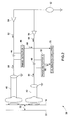
- FIG. 4 is a flow chart representing steps in an exemplary method 120 of calibrating a sensor.
- the method 120 includes storing a first information of the sensor in the sensor memory, in step 122.
- the first information is calibration data of the sensor.
- the first information is an identification number of the sensor.
- the first information is a scaling factor for the respective sensor with respect to the calibration data of a proto-sensor.
- the first information is a mathematical relationship between the clearance between the stationary and rotating components and the clearance measurement signal from the sensor.
- the method 120 further includes storing a second information of the sensor in the electronics memory, in step 124.
- the second information is calibration data of various sensors with a respective identification number for each calibration data point.
- the second information may be a single calibration data point of a proto-sensor.
- the electronics interface communicates with the sensor memory and in step 128 the electronics interface matches the sensor or the first information with its respective plurality of calibration data or the second information.
- the electronics interface downloads the calibration data of the sensor from the sensor memory.
- the electronics interface determines the sensor identification number from the sensor memory and then matches the sensor identification number to the respective plurality of calibration data stored in the electronics interface memory.
- the electronics interface reads the scaling factor from the sensor memory and applies it to the proto-calibration data stored in the electronics interface memory and generates new calibration data for the sensor.
- the electronics interface determines the mathematical relationship from the sensor memory and uses the mathematical relationship to calculate the clearance between the stationary and the rotating component of the rotary machine. In operation of the rotary machine, the electronics interface periodically queries the sensor memory to detect whether the old sensor is replace by a new sensor. If the replacement is detected, then the electronics interface updates the calibration data.
- the electronics interface flags an operator to download the new calibration data in the electronics interface memory. The operator then manually enters the calibration data of the sensor in the electronics interface memory. Thus, it eliminates the possibility of mismatch between the sensor and the calibration data.
- the sensor memory is a read/write memory.
- the electronics interface tracks the sensor deterioration over time. Revised calibration data is periodically downloaded to the sensor memory. In the event that the electronics box needs to be replaced, the sensor data corresponding to the initial sensor specific calibration, plus the deterioration tracked calibration information are both available to the new electronics box.
- the sensor memory also acts as a history of sensor usage and health.
Landscapes
- Engineering & Computer Science (AREA)
- Mechanical Engineering (AREA)
- General Engineering & Computer Science (AREA)
- Physics & Mathematics (AREA)
- General Physics & Mathematics (AREA)
- Measurement Of Length, Angles, Or The Like Using Electric Or Magnetic Means (AREA)
Abstract
Description
- The present description relates generally to a method and a system for automatic download of calibration data of a sensor into electronics interface of a sensor system, and more specifically to conveying physical sensor parameters to the electronics interface.
- Various types of sensor systems are used to measure various parameters. In addition, such sensor systems are used in various applications. For example, in turbine systems, the sensor systems are used to measure a clearance between a static shroud and turbine blades. Such sensor systems typically include sensors and electronics interface. In general, the sensor output may not provide the signal indicative of a parameter to be measured. The electronics interface is configured to convert the sensor output signal to a signal representative of the parameter to be measured or in other words to provide a calibrated result. The conversion from the sensor output signal to the signal representative of the parameter to be measured is based on the sensor characteristics or calibration data of the sensor.
- New installations of sensors in the sensor system cause sensor variations. This results in significant error in the measurement if the electronics interface is not calibrated accordingly. Sensor variations include manufacturing variations or performance variations. In general, a very tight constraint on manufacturing is required to obtain calibrated results across manufactured sensors. Various methods have been utilized to obtain the calibrated result in presence of sensor variations. One such method is manual calibration of the electronics interface. However, the manual calibration procedure significantly increases the installation time of the new sensor. It further requires a higher training level for the personnel required for the sensor installation. Another method is to install a new electronics interface along with the new sensor installation. The new electronics interface is coupled to the new sensor and is calibrated with the calibration data of that sensor. However, replacing both the sensor and the electronics interface reduces the flexibility of inventory management and reduces the overall life of the system to that of the shortest life component.
- In some instances, the sensor performance may be a function of the combination of the sensor element, cabling and electronics. Requiring that the three components be replaced at the same time poses difficulty in installation. It the case of aircraft engine installations for example, it is desirable to maintain the cabling even if the sensor element or electronics need to be replaced. This avoids costly and time consuming wire routing.
- Thus, there is a need for a method or a system to obtain desired calibrated results in presence of the sensor variations and without the need of manual calibration.
- In accordance with one exemplary embodiment of the present invention, a sensor system is provided. The system includes a clearance sensor for measuring a clearance parameter between a stationary component and a rotating component of a rotating machine and to output a clearance measurement signal. The system also includes a sensor memory attached to the sensor. A first sensor information is stored in the sensor memory. The system further includes a electronics interface memory for storing a second sensor information and an electronics interface, which reads the first and the second sensor information and matches the clearance sensor with a respective plurality of calibration data based on the first and the second sensor information.
- In accordance with another exemplary embodiment of the present invention, a method for calibrating a clearance sensor is provided. The method includes storing a first sensor information in a clearance sensor memory. The method also includes storing a second sensor information in a electronics interface memory and reading the first sensor information from the clearance sensor memory. The method further includes calibrating the clearance sensor based on the first sensor information and the second sensor information.
- In accordance with one embodiment of the present invention, a calibrated sensor is provided. The sensor includes a sensor element and a memory coupled to the sensor element. A plurality of sensor specific information is stored in the memory.
- There follows a detailed description of embodiments of the invention by way of example only with reference to the accompanying drawings, in which:
-
FIG. 1 is a diagrammatical representation of a rotating machine having a sensor system, in accordance with an embodiment of the present invention; -
FIG. 2 is a diagrammatical representation of a sensor system ofFIG. 1 , in accordance with an embodiment of the present invention; -
FIG. 3 is a diagrammatical representation of a calibration system ofFIG. 1 , in accordance with an embodiment of the present invention; and -
FIG. 4 is a flowchart illustrating steps of calibration of the sensor system, in accordance with an embodiment of the present invention. - As discussed in detail herein, embodiments of the invention include a system and a method for self-calibration of clearance measurement system. Although the present discussion focuses on clearance measurement systems, it is applicable to any measurement system, such as a temperature measurement system or a pressure measurement system.
-
FIG. 1 is a perspective view of an exemplary rotating machine, such as anaircraft engine turbine 10, wherein aspects of the present technique can be incorporated. It should be noted here, however, that the present technique can be used in any other rotating machine such as but not limited to steam turbine and gas turbine. The turbine includes arotor 12 mounted on ashaft 14. A plurality ofturbine blades 16, are affixed to therotor 12. In operation, theblades 16 are subject to afluid 18 or steam at a high temperature and pressure, which does work on theblades 16 and causes them to rotate about anaxis 20. Theblades 16 rotate within a stationary housing orshroud 22 that is positioned approximately radially and circumferentially around the blades. There is a relatively small clearance between theblades 16 and theshroud 22 to prevent excessive leakage of the working fluid between theblades 16 and theshroud 22. In the ideal no loss system, there should be no clearance, so all the fluid will work onblades 16 only. However, that configuration will make movement of blades impossible due to the resistance between theblades 16 and theshroud 22 or to prevent rubs between therotor blades 16 and theshroud 22. A zero clearance system is also impractical because of vibrations. - In one embodiment, one or
more clearance sensors 24 are disposed within and circumferentially around thestationary shroud 22. In the illustrated embodiment, theclearance sensors 24 include capacitive probes. Capacitive probe sensors provide variable capacitance as a representation of the clearance. In certain embodiments, theclearance sensors 24 may include microwave based sensors, optical sensors, or eddy current sensors. Each of thesensors 24 is configured to generate a signal indicative of a radial and/or an axial position of theblades 16 with respect to theshroud 22 at their respective circumferential locations. Thesensor signals 26 are transmitted to aclearance measurement system 28 for measuring the clearance. Further, the clearance measurement through theclearance measurement system 28 is used for controlling the clearance between theshroud 22 and theturbine blades 16 via aclearance control system 30. -
Fig. 2 illustrates an exemplary configuration of aclearance measurement system 28 ofFig. 1 . Thesystem 28 in this embodiment comprises first andsecond sensors shroud 22 and therotor blades 16 of steam turbine ofFig. 1 . - In this example, the
clearance 32 between the shroud and the rotor blades of the turbine is calculated by ratiometric techniques from first and second signals of first andsecond sensors bidirectional coupler 44 and aphase detector 46 are coupled to thefirst sensor 40 for measuring the capacitance through thefirst sensor 40. Similarly, abidirectional coupler 48 and aphase detector 50 are coupled to thesecond sensor 42 for measuring the capacitance through thesecond sensor 42. Asignal generator 52 is coupled to the first andsecond sensors second amplifiers signal generator 52 to amplify input signals generated from thesignal generator 52. Theamplifiers sensors signal generator 52 and thephase detectors - According to one embodiment, the
signal generator 52 at an excitation frequency excites first andsecond sensors signal excited signal second sensors first sensor 40 is measured by measuring a phase difference between theexcitation signal 62 and the corresponding reflectedsignal 58 by thebidirectional coupler 44 and thephase detector 46. Thephase detector 46 is configured to detect a first reflectedsignal 58 based upon the excitation frequency to generatefirst measurement signal 66. Similarly, measuring a phase difference between theexcitation signal 64 and the corresponding reflectedsignal 60 by thebidirectional coupler 48 and thephase detector 50 generates thesecond measurement signal 68 representative of the capacitance through thesecond sensor 42. The first and second measurement signals 66 and 68 are then transmitted to acalibration circuitry 70 for calculation of the clearance based upon a function of the first and second measurement signals 66 and 68. In one embodiment the function is a ratio between first and second measurement signals. Thecalibration circuitry 70 further communicates withsensors sensor system 28 in this example employs twosensors rotor blades 22 and theshroud 16. However, other configurations of the sensor system having more sensors are within the scope of the system. -
FIG. 3 shows acalibration system 90 of the rotating machine ofFIG. 1 . In this embodiment afirst memory 98 is attached to theclearance sensor 96. Thefirst memory 98 is configured to store sensor specific information. In one embodiment, the sensor specific information is a sensor identification number. In another embodiment, the specific information may be sensor geometry information. In yet another embodiment, the sensor geometry & tolerance are specified so that the probes have nearly a same response. However, the geometry differences across probes can be calibrated out using the sensor memory thereby easing the specs on manufacturing tolerance. In yet another embodiment, the sensor specific information may be calibration data of the sensor. An electronics interface 92 includes anelectronic circuitry 100 and asecond memory 94. Theelectronics circuitry 100 then downloads the sensor specific information from thefirst memory 98 of theclearance sensor 96 and to thesecond memory 94 attached to an electronic circuitry. A calibration module then uses the data stored in thesecond memory 94 and the signals from thephase detectors FIG. 2 and outputs a signal representing the clearance between a stationary and a rotating body of the rotating machine. - For gas turbine engine applications, the temperature at the sensor location is generally 600 to 800 Fahrenheit. Thus, the
first memory 98 needs to survive and retain the data at such high temperatures. In one embodiment, the data in thefirst memory 98 is downloaded to the second memory by the electronics interface only at the start of the sensor installation. In this embodiment, a memory that can withstand high temperature for a short duration may be envisaged. In this embodiment, the second memory is located in or near the sensor electronics which is located at a cooler location, or otherwise supplied with a means of active cooling to maintain the temperature within the limits of operation of electronic devices. - Various types of memories can be used to store the sensor specific information, such as electrical memory, electronic non-volatile memory (electronic NVM) and mechanical memory. Electrical memories are analog in nature. In other words, it consists of an analog circuit. The electrical memory is expandable by adding multiple memory elements in parallel. In one embodiment, each memory element consists of a resistive network, wherein a resistor value is chosen according to a scaling ratio from a proto-calibration curve. Addition of each memory element requires additional wiring in the memory circuit. Thus, memory expansion of electrical memories requires complex wiring. The resolution of these memories is generally low. In one embodiment the resolution is 8 bits. In another embodiment, each element consists of a resonance circuit the resonance frequency of which is chosen according to a scaling ratio from a proto-calibration curve. In yet another embodiment, the memory may include a combination of resistive network and resonance circuit. It should be noted here that the invention is not restricted to resistive or resonance circuit, other similar elements and combination of elements is also within the scope of this invention.
- In one embodiment, a number of electrical memory elements are connected through an electrically controlled switch to sequentially connect (multiplex) the elements to the wiring. A large number of element may be multiplexed on a single set of wires reducing the wiring complexity while providing a large number of stored parameters.
- Electronic NVM retain stored information even without a power source. Electronically Erasable Programmable Read Only Memory (EEPROM) is one type of electronic NVM. EEPROM can be programmed and erased electrically using field emission (more commonly known as "Fowler-Nordheim tunneling"). The stored information retention capability of EEPROMs deteriorate with temperature. In one embodiment the stored information retention capability of EEPROM is limited to 1250C. It should be noted, however, that EEPROMs used in automotive applications have been demonstrated up to 180°C. Serial bus interface and parallel bus interface are two main types of electrical interfaces used in EEPROM devices. EEPROM memory expansion using serial bus interface requires low wiring complexity compared to electrical memories. Another advantage of EEPROM is it can be delivered in a wide range of configurations, from 16 bits to very-high bit-count blocks greater than 1 Megabyte.
- In one embodiment, mechanical memory is used to store sensor specific information as explained earlier. The advantage of mechanical memories is they can retain stored information up to quite a high temperature. In one embodiment they can retain the information up to 4000C. Mechanical memories allow logic state information to be sequentially entered therein, and subsequently read out in the same sequence in which the information was entered into the memory. Thus, mechanical memories are also referred to as first-in-first-out (FIFO) memories. The mechanical memory can be formed as a volatile memory or as a nonvolatile memory. In one embodiment, the mechanical memory is implemented using MEMS technology.
-
FIG. 4 is a flow chart representing steps in anexemplary method 120 of calibrating a sensor. Themethod 120 includes storing a first information of the sensor in the sensor memory, instep 122. In one embodiment, the first information is calibration data of the sensor. In another embodiment, the first information is an identification number of the sensor. In one embodiment, the first information is a scaling factor for the respective sensor with respect to the calibration data of a proto-sensor. In yet another embodiment, the first information is a mathematical relationship between the clearance between the stationary and rotating components and the clearance measurement signal from the sensor. Themethod 120 further includes storing a second information of the sensor in the electronics memory, instep 124. In one embodiment, the second information is calibration data of various sensors with a respective identification number for each calibration data point. In another embodiment, the second information may be a single calibration data point of a proto-sensor. - In
step 126 of themethod 120, the electronics interface communicates with the sensor memory and instep 128 the electronics interface matches the sensor or the first information with its respective plurality of calibration data or the second information. In one embodiment, the electronics interface downloads the calibration data of the sensor from the sensor memory. In another embodiment, the electronics interface determines the sensor identification number from the sensor memory and then matches the sensor identification number to the respective plurality of calibration data stored in the electronics interface memory. In another embodiment, the electronics interface reads the scaling factor from the sensor memory and applies it to the proto-calibration data stored in the electronics interface memory and generates new calibration data for the sensor. In yet another embodiment, the electronics interface determines the mathematical relationship from the sensor memory and uses the mathematical relationship to calculate the clearance between the stationary and the rotating component of the rotary machine. In operation of the rotary machine, the electronics interface periodically queries the sensor memory to detect whether the old sensor is replace by a new sensor. If the replacement is detected, then the electronics interface updates the calibration data. - In one embodiment, if the sensor replacement is detected from a change in the sensor identification number, the electronics interface flags an operator to download the new calibration data in the electronics interface memory. The operator then manually enters the calibration data of the sensor in the electronics interface memory. Thus, it eliminates the possibility of mismatch between the sensor and the calibration data.
- In one embodiment, the sensor memory is a read/write memory. The electronics interface tracks the sensor deterioration over time. Revised calibration data is periodically downloaded to the sensor memory. In the event that the electronics box needs to be replaced, the sensor data corresponding to the initial sensor specific calibration, plus the deterioration tracked calibration information are both available to the new electronics box. Thus, in this embodiment, the sensor memory also acts as a history of sensor usage and health.
- For completeness, various aspects of the invention are now set out in the following numbered clauses:
- 1. A sensor system comprising:
- a clearance sensor configured to measure a clearance between a stationary component and a rotating component of a rotating machine and to output a clearance measurement signal;
- a sensor memory coupled to the clearance sensor and configured to store a first sensor information;
- an electronics interface memory configured to store a second sensor information; and
- an electronics interface configured to read the first and the second sensor information and to match the clearance sensor with a respective plurality of calibration data based on the first and the second sensor information.
- 2. The system of
clause 1, wherein the stationary object comprises a shroud of the rotating machine. - 3. The system of
clause 1, wherein the rotating object comprises a rotating blade of the rotating machine. - 4. The system of
clause 1, wherein the clearance sensor is selected from the group consisting of a capacitive sensor, a microwave based sensor, an optical based sensor, an eddy current sensor and combinations thereof. - 5. The system of
clause 1, wherein the sensor memory and the electronics interface memory are selected from the group consisting of an electronic memory, an electrical memory, a mechanical memory and combinations thereof. - 6. The system of
clause 1, wherein the electronics interface periodically probes the sensor memory to detect a change in the clearance sensor. - 7. The system of
clause 1, wherein the first sensor information comprises the calibration data for the clearance sensor, and wherein the electronics interface uses the calibration data to calibrate the clearance measurement signal. - 8. The system of
clause 1, wherein the first sensor information comprises a sensor identification number. - 9. The system of clause 8 wherein the electronics interface issues an alerting when a mismatch is detected between the sensor ID and the calibration parameters.
- 10. The system of
clause 1, wherein the first sensor information comprises a plurality of scaling parameters with respect to a plurality of proto-calibration data for the clearance sensor. - 11. The system of
clause 1, wherein the first sensor information comprises a mathematical relationship between the clearance between the stationary and rotating components and the clearance measurement signal. - 12. The system of
clause 1, wherein the second sensor information comprises a plurality of calibration data with a respective identification number for each of the calibration data points. - 13. The system of
clause 1, wherein the second sensor information comprises a plurality of calibration data for a proto-sensor. - 14. A method for calibrating a clearance sensor, the method comprising:
- storing a first sensor information in a clearance sensor memory;
- storing a second sensor information in a electronics interface memory;
- reading the first sensor information from the clearance sensor memory; and
- calibrating the clearance sensor based on the first sensor information and the second sensor information.
- 15. The method of
clause 14 further comprising tracking the clearance sensor deterioration over time based on the first sensor information and the second sensor information. - 16. The method of
clause 14, wherein storing a second sensor information comprises detecting a change in the clearance sensor and manually downloading a plurality of new calibration data into the electronics interface memory. - 17. The method of
clause 14, wherein the first sensor information comprises a plurality of calibration data for the clearance sensor. - 18. The method of
clause 14, wherein the first sensor information comprises a sensor identification number. - 19. The method of
clause 14, wherein the first sensor information comprises a plurality of scaling parameters with respect to a plurality of proto-calibration data for the clearance sensor. - 20. The method of
clause 14, wherein the clearance sensor is configured to monitor a clearance between a rotating component and a stationary component, and wherein the first sensor information comprises a mathematical relationship between the clearance between the stationary and rotating components and the clearance measurement signal. - 21. The method of
clause 14, wherein the second sensor information comprises a plurality of calibration data with a respective identification number for each of the calibration data points. - 22. The method of
clause 14, wherein the second sensor information comprises a plurality of calibration data for a proto-sensor. - 23. A calibrated sensor comprising
- a sensor element; and
- a memory coupled to the sensor element, wherein the memory is configured to store a plurality of sensor specific information.
- 24. The sensor of clause 23, wherein the sensor element is selected from the group consisting of a capacitive sensor element, a microwave based sensor element, an optical based sensor element, an eddy current sensor element and combinations thereof.
- 25. The sensor of clause 23, wherein the memory is selected from the group consisting of an electronic memory, an electrical memory, a mechanical memory and combinations thereof.
Claims (15)
- A sensor system (30) comprising:a clearance sensor (24) configured to measure a clearance (32) between a stationary component (22) and a rotating component (16) of a rotating machine (10) and to output a clearance measurement signal;a sensor memory (98) coupled to the clearance sensor (24) and configured to store a first sensor information;an electronics interface memory (94) configured to store a second sensor information; andan electronics interface (92) configured to read the first and the second sensor information and to match the clearance sensor with a respective plurality of calibration data based on the first and the second sensor information.
- The system of claim 1, wherein the sensor memory and the electronics interface memory are selected from the group consisting of an electronic memory, an electrical memory, a mechanical memory and combinations thereof.
- The system of claim 1 or 2, wherein the electronics interface periodically probes the sensor memory to detect a change in the clearance sensor.
- The system of any of the preceding claims, wherein the first sensor information comprises the calibration data for the clearance sensor, and wherein the electronics interface uses the calibration data to calibrate the clearance measurement signal.
- The system of any of the preceding claims, wherein the first sensor information comprises a sensor identification number.
- The system of claim 5, wherein the electronics interface issues an alerting when a mismatch is detected between the sensor ID and the calibration parameters.
- The system of any of the preceding claims, wherein the first sensor information comprises a plurality of scaling parameters with respect to a plurality of proto-calibration data for the clearance sensor.
- The system of any of the preceding claims, wherein the first sensor information comprises a mathematical relationship between the clearance between the stationary and rotating components and the clearance measurement signal.
- The system of any of the preceding claims, wherein the second sensor information comprises a plurality of calibration data with a respective identification number for each of the calibration data points.
- The system of any of the preceding claims, wherein the second sensor information comprises a plurality of calibration data for a proto-sensor.
- A method (120) for calibrating a clearance sensor, the method comprising:storing a first sensor information (122) in a clearance sensor memory;storing a second sensor information (124) in a electronics interface memory;reading the first sensor information (126) from the clearance sensor memory; andcalibrating the clearance sensor (128) based on the first sensor information and the second sensor information.
- The method of claim 11, wherein storing a second sensor information comprises detecting a change in the clearance sensor and manually downloading a plurality of new calibration data into the electronics interface memory.
- The method of claim 11 or 12, wherein the first sensor information comprises a plurality of scaling parameters with respect to a plurality of proto-calibration data for the clearance sensor.
- The method of any of claims 11 to 13, wherein the second sensor information comprises a plurality of calibration data for a proto-sensor.
- A calibrated sensor comprisinga sensor element (96); anda memory (98) coupled to the sensor element, wherein the memory is configured to store a plurality of sensor specific information.
Applications Claiming Priority (1)
| Application Number | Priority Date | Filing Date | Title |
|---|---|---|---|
| US12/360,485 US8022715B2 (en) | 2009-01-27 | 2009-01-27 | Automated sensor specific calibration through sensor parameter download |
Publications (2)
| Publication Number | Publication Date |
|---|---|
| EP2211139A1 true EP2211139A1 (en) | 2010-07-28 |
| EP2211139B1 EP2211139B1 (en) | 2020-12-23 |
Family
ID=42126010
Family Applications (1)
| Application Number | Title | Priority Date | Filing Date |
|---|---|---|---|
| EP10151311.7A Active EP2211139B1 (en) | 2009-01-27 | 2010-01-21 | Automated sensor specific calibration through sensor parameter download |
Country Status (4)
| Country | Link |
|---|---|
| US (2) | US8022715B2 (en) |
| EP (1) | EP2211139B1 (en) |
| JP (1) | JP5688904B2 (en) |
| CA (2) | CA2960539C (en) |
Cited By (5)
| Publication number | Priority date | Publication date | Assignee | Title |
|---|---|---|---|---|
| CN102183200A (en) * | 2011-03-03 | 2011-09-14 | 力帆实业(集团)股份有限公司 | Gap detecting circuit for engine speed sensor and no-load detecting method thereof |
| WO2012078239A3 (en) * | 2010-10-21 | 2012-09-07 | Siemens Energy, Inc. | A diagnostic system and method for monitoring operating conditions of components of a turbine machine |
| WO2013039728A3 (en) * | 2011-09-15 | 2013-11-07 | General Electric Company | Detection system and method for a rotating machine |
| US8996277B2 (en) | 2012-01-24 | 2015-03-31 | Rolls-Royce Plc | Gas turbine engine control |
| EP3128759A1 (en) * | 2015-08-07 | 2017-02-08 | General Electric Company | Calibration circuit and method of use |
Families Citing this family (15)
| Publication number | Priority date | Publication date | Assignee | Title |
|---|---|---|---|---|
| US7994800B2 (en) * | 2008-03-25 | 2011-08-09 | General Electric Company | Systems and methods for online phase calibration |
| FR2955387B1 (en) * | 2010-01-21 | 2012-03-09 | Commissariat Energie Atomique | MEASUREMENT OF A CYCLIC MOVEMENT OF A FERROMAGNETIC PIECE |
| US8876460B2 (en) | 2011-08-11 | 2014-11-04 | General Electric Company | Method and apparatus for measuring turbine shell clearance |
| US8922203B2 (en) | 2012-01-16 | 2014-12-30 | General Electric Company | Turbomachine blade monitoring system |
| US8970228B2 (en) | 2012-05-31 | 2015-03-03 | General Electric Company | Rotational clearance measurement system and method of operation |
| US9417048B2 (en) | 2012-10-31 | 2016-08-16 | General Electric Company | Capacitive sensor device and method of manufacture |
| JP6604939B2 (en) | 2013-03-15 | 2019-11-13 | ユナイテッド テクノロジーズ コーポレイション | Control system, control method and gas turbine engine |
| CN103206916B (en) * | 2013-03-26 | 2015-08-05 | 洛阳轴研科技股份有限公司 | A kind of signal acquisition method with V-notch revolving meber rotational angle |
| US9476318B2 (en) * | 2013-09-03 | 2016-10-25 | General Electric Company | Systems and methods to monitor a rotating component |
| US9587511B2 (en) | 2013-12-13 | 2017-03-07 | General Electric Company | Turbomachine cold clearance adjustment |
| US9574965B2 (en) * | 2014-06-24 | 2017-02-21 | General Electric Company | System and method of determining bearing health in a rotating machine |
| US10921154B2 (en) | 2015-07-22 | 2021-02-16 | Hewlett Packard Enterprise Development Lp | Monitoring a sensor array |
| JP6694307B2 (en) * | 2016-03-30 | 2020-05-13 | 株式会社キーエンス | Program that displays the measurement result of displacement meter |
| JP6963450B2 (en) * | 2017-09-22 | 2021-11-10 | 三菱パワー株式会社 | Rotating machine control device, rotating machine equipment, rotating machine control method, and rotating machine control program |
| CN116989651B (en) * | 2023-09-25 | 2023-12-26 | 科瑞工业自动化系统(苏州)有限公司 | Eddy current displacement sensor for ocean platform and calibration method thereof |
Citations (3)
| Publication number | Priority date | Publication date | Assignee | Title |
|---|---|---|---|---|
| US20030060986A1 (en) * | 1999-08-02 | 2003-03-27 | Flotow Andreas Von | Apparatus and method for predicting failures of spinning disks in turbo-machinery |
| US20050218887A1 (en) * | 2002-05-31 | 2005-10-06 | Siemens Westinghouse Power Corporation | Wear monitor for turbo-machine |
| US20070005294A1 (en) * | 2005-06-27 | 2007-01-04 | Andarawis Emad A | Clearance measurement system and method of operation |
Family Cites Families (31)
| Publication number | Priority date | Publication date | Assignee | Title |
|---|---|---|---|---|
| US4639878A (en) * | 1985-06-04 | 1987-01-27 | Gmf Robotics Corporation | Method and system for automatically determining the position and attitude of an object |
| JPS62263412A (en) * | 1986-05-09 | 1987-11-16 | Shimizu Constr Co Ltd | Measurement processing system |
| SE464855B (en) * | 1986-09-29 | 1991-06-24 | Asea Ab | PROCEDURE OF AN INDUSTRIAL BOTTOM FOR CALIBRATION OF A SENSOR |
| JPH0184113U (en) * | 1987-11-20 | 1989-06-05 | ||
| US4987555A (en) * | 1988-11-30 | 1991-01-22 | Westinghouse Electric Corp. | Turbine blade shroud clearance monitor |
| JPH09141473A (en) * | 1995-11-22 | 1997-06-03 | Shibuya Kogyo Co Ltd | Laser beam processing machine of head section exchange type |
| DE59605246D1 (en) * | 1996-02-16 | 2000-06-21 | Heidenhain Gmbh Dr Johannes | Device and method for switching between different operating modes of a sensor |
| US6003640A (en) * | 1997-05-09 | 1999-12-21 | The B.F. Goodrich Company | Electronic braking system with brake wear measurement and running clearance adjustment |
| JPH11123573A (en) * | 1997-10-15 | 1999-05-11 | Amada Co Ltd | Method and device for calibration of gap sensor in machining head |
| JP2000002682A (en) * | 1998-06-12 | 2000-01-07 | Horiba Ltd | Gas analyzer |
| JP4643782B2 (en) * | 1999-12-10 | 2011-03-02 | 株式会社キーエンス | Eddy current displacement meter and distance measurement method using it |
| EP2272688B1 (en) * | 2000-07-26 | 2012-02-01 | Bridgestone Americas Tire Operations, LLC | Electronic tire management system |
| US7161476B2 (en) | 2000-07-26 | 2007-01-09 | Bridgestone Firestone North American Tire, Llc | Electronic tire management system |
| JP3827549B2 (en) * | 2001-10-04 | 2006-09-27 | 株式会社ミツトヨ | Probe calibration method and calibration program |
| US6717418B2 (en) * | 2001-11-16 | 2004-04-06 | General Electric Company | Method and apparatus for measuring turbine blade tip clearance |
| JP2004219320A (en) * | 2003-01-16 | 2004-08-05 | Murata Mach Ltd | Sensor having error correction function |
| JP4251356B2 (en) * | 2003-12-03 | 2009-04-08 | 株式会社山武 | Individual information provision system |
| GB2411960B8 (en) | 2004-03-11 | 2006-11-30 | Transense Technologies Plc | Method and apparatus for electronic storing of calibration/identification data for a wirelss linear passive sensor |
| JP2005315707A (en) * | 2004-04-28 | 2005-11-10 | Nikon Corp | Temperature measuring apparatus, exposure apparatus, and device manufacturing method |
| JP2006029931A (en) * | 2004-07-15 | 2006-02-02 | Hitachi Ltd | Building structure damage detection device |
| US7332915B2 (en) | 2004-09-28 | 2008-02-19 | General Electric Company | Sensor system and method of operating the same |
| US7180305B2 (en) | 2004-12-14 | 2007-02-20 | General Electric Company | Sensor systems and methods of operation |
| US7722310B2 (en) | 2004-12-17 | 2010-05-25 | General Electric Company | System and method for measuring clearance between two objects |
| US8591188B2 (en) | 2005-04-26 | 2013-11-26 | General Electric Company | Displacement sensor system and method of operation |
| US7466143B2 (en) | 2005-09-16 | 2008-12-16 | General Electric Company | Clearance measurement systems and methods of operation |
| US7652489B2 (en) * | 2005-12-06 | 2010-01-26 | General Electric Company | Multi-range clearance measurement system and method of operation |
| JP4783142B2 (en) * | 2005-12-26 | 2011-09-28 | 株式会社共和電業 | Sensor body and strain measuring device using the sensor body |
| US7415389B2 (en) * | 2005-12-29 | 2008-08-19 | Honeywell International Inc. | Calibration of engine control systems |
| US7215129B1 (en) * | 2006-03-30 | 2007-05-08 | General Electric Company | Multi tip clearance measurement system and method of operation |
| US7404331B2 (en) | 2006-09-27 | 2008-07-29 | General Electric Company | Sensor assembly, transformers and methods of manufacture |
| US8177474B2 (en) | 2007-06-26 | 2012-05-15 | General Electric Company | System and method for turbine engine clearance control with rub detection |
-
2009
- 2009-01-27 US US12/360,485 patent/US8022715B2/en active Active
-
2010
- 2010-01-14 CA CA2960539A patent/CA2960539C/en active Active
- 2010-01-14 CA CA2690215A patent/CA2690215C/en active Active
- 2010-01-21 EP EP10151311.7A patent/EP2211139B1/en active Active
- 2010-01-25 JP JP2010012681A patent/JP5688904B2/en active Active
-
2011
- 2011-08-10 US US13/206,740 patent/US8536878B2/en active Active
Patent Citations (3)
| Publication number | Priority date | Publication date | Assignee | Title |
|---|---|---|---|---|
| US20030060986A1 (en) * | 1999-08-02 | 2003-03-27 | Flotow Andreas Von | Apparatus and method for predicting failures of spinning disks in turbo-machinery |
| US20050218887A1 (en) * | 2002-05-31 | 2005-10-06 | Siemens Westinghouse Power Corporation | Wear monitor for turbo-machine |
| US20070005294A1 (en) * | 2005-06-27 | 2007-01-04 | Andarawis Emad A | Clearance measurement system and method of operation |
Cited By (8)
| Publication number | Priority date | Publication date | Assignee | Title |
|---|---|---|---|---|
| WO2012078239A3 (en) * | 2010-10-21 | 2012-09-07 | Siemens Energy, Inc. | A diagnostic system and method for monitoring operating conditions of components of a turbine machine |
| US8515711B2 (en) | 2010-10-21 | 2013-08-20 | Siemens Energy, Inc. | Diagnostic system and method for monitoring operating conditions of components of a turbine machine |
| KR101503669B1 (en) * | 2010-10-21 | 2015-03-19 | 지멘스 에너지, 인코포레이티드 | A diagnostic system and method for monitoring operating conditions of components of a turbine machine |
| CN102183200A (en) * | 2011-03-03 | 2011-09-14 | 力帆实业(集团)股份有限公司 | Gap detecting circuit for engine speed sensor and no-load detecting method thereof |
| WO2013039728A3 (en) * | 2011-09-15 | 2013-11-07 | General Electric Company | Detection system and method for a rotating machine |
| US8996277B2 (en) | 2012-01-24 | 2015-03-31 | Rolls-Royce Plc | Gas turbine engine control |
| EP3128759A1 (en) * | 2015-08-07 | 2017-02-08 | General Electric Company | Calibration circuit and method of use |
| US9760748B2 (en) | 2015-08-07 | 2017-09-12 | General Electric Company | Calibration circuit and method of use |
Also Published As
| Publication number | Publication date |
|---|---|
| US8022715B2 (en) | 2011-09-20 |
| US8536878B2 (en) | 2013-09-17 |
| EP2211139B1 (en) | 2020-12-23 |
| CA2960539A1 (en) | 2010-07-27 |
| JP5688904B2 (en) | 2015-03-25 |
| US20110295538A1 (en) | 2011-12-01 |
| CA2690215C (en) | 2017-05-09 |
| CA2690215A1 (en) | 2010-07-27 |
| CA2960539C (en) | 2019-07-09 |
| JP2010175539A (en) | 2010-08-12 |
| US20100188100A1 (en) | 2010-07-29 |
Similar Documents
| Publication | Publication Date | Title |
|---|---|---|
| US8022715B2 (en) | Automated sensor specific calibration through sensor parameter download | |
| EP1995577B1 (en) | Temperature sensing | |
| EP1445450B1 (en) | Method for monitoring the performance of a gas turbine system | |
| EP1505279B1 (en) | Fuel control for gas turbine engines | |
| KR20070099440A (en) | How to detect the status of multi-tip gap measuring device, gap measuring method, rotating device and multi-tip gap measuring device | |
| EP2578811B1 (en) | Method for determining position of rotating blades having variable thickness. | |
| EP2026040B1 (en) | Sensor arrangement | |
| EP2035769A1 (en) | Vibration and condition monitoring system and the parts thereof | |
| US7768258B2 (en) | Proximity probe transmitter | |
| US6848193B1 (en) | Methods and systems for machine monitoring system calibration | |
| US9395171B2 (en) | Capacitive sensor with orthogonal fields | |
| US9709979B2 (en) | Method of monitoring short circuits in torque motors | |
| Satish et al. | Investigation into the development and testing of a simplex capacitance sensor for rotor tip clearance measurement in turbo machinery | |
| US11687393B2 (en) | Computer-implemented methods, apparatus, computer programs, and non-transitory computer readable storage mediums for determining a value of a parameter of a system | |
| CN115298522B (en) | Method for operating a coriolis measuring device | |
| US7141985B2 (en) | Field programmable driver/transmitter for a proximity probe | |
| EP3742139A1 (en) | Testing method for non-invasive temperature measuring instruments | |
| EP4718034A1 (en) | Detection of change in the relative position of beta sensors to beta ring | |
| EP4718035A1 (en) | Detection of change in the relative position of beta sensors | |
| CN113357015A (en) | System, program product, and method for detecting thermal stability within a gas turbine system | |
| RU2358238C2 (en) | System and method of measuring clearance |
Legal Events
| Date | Code | Title | Description |
|---|---|---|---|
| PUAI | Public reference made under article 153(3) epc to a published international application that has entered the european phase |
Free format text: ORIGINAL CODE: 0009012 |
|
| AK | Designated contracting states |
Kind code of ref document: A1 Designated state(s): AT BE BG CH CY CZ DE DK EE ES FI FR GB GR HR HU IE IS IT LI LT LU LV MC MK MT NL NO PL PT RO SE SI SK SM TR |
|
| AX | Request for extension of the european patent |
Extension state: AL BA RS |
|
| 17P | Request for examination filed |
Effective date: 20110128 |
|
| STAA | Information on the status of an ep patent application or granted ep patent |
Free format text: STATUS: EXAMINATION IS IN PROGRESS |
|
| 17Q | First examination report despatched |
Effective date: 20170823 |
|
| GRAP | Despatch of communication of intention to grant a patent |
Free format text: ORIGINAL CODE: EPIDOSNIGR1 |
|
| STAA | Information on the status of an ep patent application or granted ep patent |
Free format text: STATUS: GRANT OF PATENT IS INTENDED |
|
| INTG | Intention to grant announced |
Effective date: 20191203 |
|
| GRAJ | Information related to disapproval of communication of intention to grant by the applicant or resumption of examination proceedings by the epo deleted |
Free format text: ORIGINAL CODE: EPIDOSDIGR1 |
|
| STAA | Information on the status of an ep patent application or granted ep patent |
Free format text: STATUS: EXAMINATION IS IN PROGRESS |
|
| INTC | Intention to grant announced (deleted) | ||
| GRAP | Despatch of communication of intention to grant a patent |
Free format text: ORIGINAL CODE: EPIDOSNIGR1 |
|
| STAA | Information on the status of an ep patent application or granted ep patent |
Free format text: STATUS: GRANT OF PATENT IS INTENDED |
|
| INTG | Intention to grant announced |
Effective date: 20200715 |
|
| GRAS | Grant fee paid |
Free format text: ORIGINAL CODE: EPIDOSNIGR3 |
|
| GRAA | (expected) grant |
Free format text: ORIGINAL CODE: 0009210 |
|
| STAA | Information on the status of an ep patent application or granted ep patent |
Free format text: STATUS: THE PATENT HAS BEEN GRANTED |
|
| AK | Designated contracting states |
Kind code of ref document: B1 Designated state(s): AT BE BG CH CY CZ DE DK EE ES FI FR GB GR HR HU IE IS IT LI LT LU LV MC MK MT NL NO PL PT RO SE SI SK SM TR |
|
| REG | Reference to a national code |
Ref country code: GB Ref legal event code: FG4D |
|
| REG | Reference to a national code |
Ref country code: DE Ref legal event code: R096 Ref document number: 602010066188 Country of ref document: DE |
|
| REG | Reference to a national code |
Ref country code: AT Ref legal event code: REF Ref document number: 1348154 Country of ref document: AT Kind code of ref document: T Effective date: 20210115 |
|
| REG | Reference to a national code |
Ref country code: IE Ref legal event code: FG4D |
|
| PG25 | Lapsed in a contracting state [announced via postgrant information from national office to epo] |
Ref country code: GR Free format text: LAPSE BECAUSE OF FAILURE TO SUBMIT A TRANSLATION OF THE DESCRIPTION OR TO PAY THE FEE WITHIN THE PRESCRIBED TIME-LIMIT Effective date: 20210324 Ref country code: FI Free format text: LAPSE BECAUSE OF FAILURE TO SUBMIT A TRANSLATION OF THE DESCRIPTION OR TO PAY THE FEE WITHIN THE PRESCRIBED TIME-LIMIT Effective date: 20201223 Ref country code: NO Free format text: LAPSE BECAUSE OF FAILURE TO SUBMIT A TRANSLATION OF THE DESCRIPTION OR TO PAY THE FEE WITHIN THE PRESCRIBED TIME-LIMIT Effective date: 20210323 |
|
| REG | Reference to a national code |
Ref country code: AT Ref legal event code: MK05 Ref document number: 1348154 Country of ref document: AT Kind code of ref document: T Effective date: 20201223 |
|
| REG | Reference to a national code |
Ref country code: NL Ref legal event code: MP Effective date: 20201223 |
|
| PG25 | Lapsed in a contracting state [announced via postgrant information from national office to epo] |
Ref country code: LV Free format text: LAPSE BECAUSE OF FAILURE TO SUBMIT A TRANSLATION OF THE DESCRIPTION OR TO PAY THE FEE WITHIN THE PRESCRIBED TIME-LIMIT Effective date: 20201223 Ref country code: SE Free format text: LAPSE BECAUSE OF FAILURE TO SUBMIT A TRANSLATION OF THE DESCRIPTION OR TO PAY THE FEE WITHIN THE PRESCRIBED TIME-LIMIT Effective date: 20201223 Ref country code: BG Free format text: LAPSE BECAUSE OF FAILURE TO SUBMIT A TRANSLATION OF THE DESCRIPTION OR TO PAY THE FEE WITHIN THE PRESCRIBED TIME-LIMIT Effective date: 20210323 |
|
| PG25 | Lapsed in a contracting state [announced via postgrant information from national office to epo] |
Ref country code: HR Free format text: LAPSE BECAUSE OF FAILURE TO SUBMIT A TRANSLATION OF THE DESCRIPTION OR TO PAY THE FEE WITHIN THE PRESCRIBED TIME-LIMIT Effective date: 20201223 Ref country code: NL Free format text: LAPSE BECAUSE OF FAILURE TO SUBMIT A TRANSLATION OF THE DESCRIPTION OR TO PAY THE FEE WITHIN THE PRESCRIBED TIME-LIMIT Effective date: 20201223 |
|
| REG | Reference to a national code |
Ref country code: LT Ref legal event code: MG9D |
|
| PG25 | Lapsed in a contracting state [announced via postgrant information from national office to epo] |
Ref country code: LT Free format text: LAPSE BECAUSE OF FAILURE TO SUBMIT A TRANSLATION OF THE DESCRIPTION OR TO PAY THE FEE WITHIN THE PRESCRIBED TIME-LIMIT Effective date: 20201223 Ref country code: CZ Free format text: LAPSE BECAUSE OF FAILURE TO SUBMIT A TRANSLATION OF THE DESCRIPTION OR TO PAY THE FEE WITHIN THE PRESCRIBED TIME-LIMIT Effective date: 20201223 Ref country code: EE Free format text: LAPSE BECAUSE OF FAILURE TO SUBMIT A TRANSLATION OF THE DESCRIPTION OR TO PAY THE FEE WITHIN THE PRESCRIBED TIME-LIMIT Effective date: 20201223 Ref country code: RO Free format text: LAPSE BECAUSE OF FAILURE TO SUBMIT A TRANSLATION OF THE DESCRIPTION OR TO PAY THE FEE WITHIN THE PRESCRIBED TIME-LIMIT Effective date: 20201223 Ref country code: SK Free format text: LAPSE BECAUSE OF FAILURE TO SUBMIT A TRANSLATION OF THE DESCRIPTION OR TO PAY THE FEE WITHIN THE PRESCRIBED TIME-LIMIT Effective date: 20201223 Ref country code: PT Free format text: LAPSE BECAUSE OF FAILURE TO SUBMIT A TRANSLATION OF THE DESCRIPTION OR TO PAY THE FEE WITHIN THE PRESCRIBED TIME-LIMIT Effective date: 20210423 Ref country code: SM Free format text: LAPSE BECAUSE OF FAILURE TO SUBMIT A TRANSLATION OF THE DESCRIPTION OR TO PAY THE FEE WITHIN THE PRESCRIBED TIME-LIMIT Effective date: 20201223 |
|
| PG25 | Lapsed in a contracting state [announced via postgrant information from national office to epo] |
Ref country code: AT Free format text: LAPSE BECAUSE OF FAILURE TO SUBMIT A TRANSLATION OF THE DESCRIPTION OR TO PAY THE FEE WITHIN THE PRESCRIBED TIME-LIMIT Effective date: 20201223 Ref country code: PL Free format text: LAPSE BECAUSE OF FAILURE TO SUBMIT A TRANSLATION OF THE DESCRIPTION OR TO PAY THE FEE WITHIN THE PRESCRIBED TIME-LIMIT Effective date: 20201223 |
|
| REG | Reference to a national code |
Ref country code: CH Ref legal event code: PL |
|
| REG | Reference to a national code |
Ref country code: DE Ref legal event code: R097 Ref document number: 602010066188 Country of ref document: DE |
|
| PG25 | Lapsed in a contracting state [announced via postgrant information from national office to epo] |
Ref country code: LU Free format text: LAPSE BECAUSE OF NON-PAYMENT OF DUE FEES Effective date: 20210121 Ref country code: MC Free format text: LAPSE BECAUSE OF FAILURE TO SUBMIT A TRANSLATION OF THE DESCRIPTION OR TO PAY THE FEE WITHIN THE PRESCRIBED TIME-LIMIT Effective date: 20201223 Ref country code: IS Free format text: LAPSE BECAUSE OF FAILURE TO SUBMIT A TRANSLATION OF THE DESCRIPTION OR TO PAY THE FEE WITHIN THE PRESCRIBED TIME-LIMIT Effective date: 20210423 |
|
| REG | Reference to a national code |
Ref country code: BE Ref legal event code: MM Effective date: 20210131 |
|
| PG25 | Lapsed in a contracting state [announced via postgrant information from national office to epo] |
Ref country code: IT Free format text: LAPSE BECAUSE OF FAILURE TO SUBMIT A TRANSLATION OF THE DESCRIPTION OR TO PAY THE FEE WITHIN THE PRESCRIBED TIME-LIMIT Effective date: 20201223 |
|
| PLBE | No opposition filed within time limit |
Free format text: ORIGINAL CODE: 0009261 |
|
| STAA | Information on the status of an ep patent application or granted ep patent |
Free format text: STATUS: NO OPPOSITION FILED WITHIN TIME LIMIT |
|
| PG25 | Lapsed in a contracting state [announced via postgrant information from national office to epo] |
Ref country code: LI Free format text: LAPSE BECAUSE OF NON-PAYMENT OF DUE FEES Effective date: 20210131 Ref country code: CH Free format text: LAPSE BECAUSE OF NON-PAYMENT OF DUE FEES Effective date: 20210131 Ref country code: ES Free format text: LAPSE BECAUSE OF FAILURE TO SUBMIT A TRANSLATION OF THE DESCRIPTION OR TO PAY THE FEE WITHIN THE PRESCRIBED TIME-LIMIT Effective date: 20201223 Ref country code: DK Free format text: LAPSE BECAUSE OF FAILURE TO SUBMIT A TRANSLATION OF THE DESCRIPTION OR TO PAY THE FEE WITHIN THE PRESCRIBED TIME-LIMIT Effective date: 20201223 |
|
| 26N | No opposition filed |
Effective date: 20210924 |
|
| PG25 | Lapsed in a contracting state [announced via postgrant information from national office to epo] |
Ref country code: IE Free format text: LAPSE BECAUSE OF NON-PAYMENT OF DUE FEES Effective date: 20210121 |
|
| PG25 | Lapsed in a contracting state [announced via postgrant information from national office to epo] |
Ref country code: SI Free format text: LAPSE BECAUSE OF FAILURE TO SUBMIT A TRANSLATION OF THE DESCRIPTION OR TO PAY THE FEE WITHIN THE PRESCRIBED TIME-LIMIT Effective date: 20201223 |
|
| PG25 | Lapsed in a contracting state [announced via postgrant information from national office to epo] |
Ref country code: IS Free format text: LAPSE BECAUSE OF FAILURE TO SUBMIT A TRANSLATION OF THE DESCRIPTION OR TO PAY THE FEE WITHIN THE PRESCRIBED TIME-LIMIT Effective date: 20210423 |
|
| PG25 | Lapsed in a contracting state [announced via postgrant information from national office to epo] |
Ref country code: BE Free format text: LAPSE BECAUSE OF NON-PAYMENT OF DUE FEES Effective date: 20210131 |
|
| PG25 | Lapsed in a contracting state [announced via postgrant information from national office to epo] |
Ref country code: HU Free format text: LAPSE BECAUSE OF FAILURE TO SUBMIT A TRANSLATION OF THE DESCRIPTION OR TO PAY THE FEE WITHIN THE PRESCRIBED TIME-LIMIT; INVALID AB INITIO Effective date: 20100121 Ref country code: CY Free format text: LAPSE BECAUSE OF FAILURE TO SUBMIT A TRANSLATION OF THE DESCRIPTION OR TO PAY THE FEE WITHIN THE PRESCRIBED TIME-LIMIT Effective date: 20201223 |
|
| P01 | Opt-out of the competence of the unified patent court (upc) registered |
Effective date: 20230414 |
|
| PG25 | Lapsed in a contracting state [announced via postgrant information from national office to epo] |
Ref country code: MK Free format text: LAPSE BECAUSE OF FAILURE TO SUBMIT A TRANSLATION OF THE DESCRIPTION OR TO PAY THE FEE WITHIN THE PRESCRIBED TIME-LIMIT Effective date: 20201223 |
|
| PG25 | Lapsed in a contracting state [announced via postgrant information from national office to epo] |
Ref country code: TR Free format text: LAPSE BECAUSE OF FAILURE TO SUBMIT A TRANSLATION OF THE DESCRIPTION OR TO PAY THE FEE WITHIN THE PRESCRIBED TIME-LIMIT Effective date: 20201223 |
|
| PG25 | Lapsed in a contracting state [announced via postgrant information from national office to epo] |
Ref country code: MT Free format text: LAPSE BECAUSE OF FAILURE TO SUBMIT A TRANSLATION OF THE DESCRIPTION OR TO PAY THE FEE WITHIN THE PRESCRIBED TIME-LIMIT Effective date: 20201223 |
|
| PGFP | Annual fee paid to national office [announced via postgrant information from national office to epo] |
Ref country code: GB Payment date: 20251220 Year of fee payment: 17 |
|
| PGFP | Annual fee paid to national office [announced via postgrant information from national office to epo] |
Ref country code: FR Payment date: 20251218 Year of fee payment: 17 |
|
| PGFP | Annual fee paid to national office [announced via postgrant information from national office to epo] |
Ref country code: DE Payment date: 20251217 Year of fee payment: 17 |