EP2210679A1 - Recoiling facility of magnesium alloy sheet - Google Patents
Recoiling facility of magnesium alloy sheet Download PDFInfo
- Publication number
- EP2210679A1 EP2210679A1 EP08840702A EP08840702A EP2210679A1 EP 2210679 A1 EP2210679 A1 EP 2210679A1 EP 08840702 A EP08840702 A EP 08840702A EP 08840702 A EP08840702 A EP 08840702A EP 2210679 A1 EP2210679 A1 EP 2210679A1
- Authority
- EP
- European Patent Office
- Prior art keywords
- magnesium alloy
- alloy sheet
- trimmer
- heating furnace
- coil material
- Prior art date
- Legal status (The legal status is an assumption and is not a legal conclusion. Google has not performed a legal analysis and makes no representation as to the accuracy of the status listed.)
- Granted
Links
Images

Classifications
-
- B—PERFORMING OPERATIONS; TRANSPORTING
- B21—MECHANICAL METAL-WORKING WITHOUT ESSENTIALLY REMOVING MATERIAL; PUNCHING METAL
- B21C—MANUFACTURE OF METAL SHEETS, WIRE, RODS, TUBES, PROFILES OR LIKE SEMI-MANUFACTURED PRODUCTS OTHERWISE THAN BY ROLLING; AUXILIARY OPERATIONS USED IN CONNECTION WITH METAL-WORKING WITHOUT ESSENTIALLY REMOVING MATERIAL
- B21C47/00—Winding-up, coiling or winding-off metal wire, metal band or other flexible metal material characterised by features relevant to metal processing only
- B21C47/02—Winding-up or coiling
- B21C47/04—Winding-up or coiling on or in reels or drums, without using a moving guide
-
- B—PERFORMING OPERATIONS; TRANSPORTING
- B21—MECHANICAL METAL-WORKING WITHOUT ESSENTIALLY REMOVING MATERIAL; PUNCHING METAL
- B21C—MANUFACTURE OF METAL SHEETS, WIRE, RODS, TUBES, PROFILES OR LIKE SEMI-MANUFACTURED PRODUCTS OTHERWISE THAN BY ROLLING; AUXILIARY OPERATIONS USED IN CONNECTION WITH METAL-WORKING WITHOUT ESSENTIALLY REMOVING MATERIAL
- B21C47/00—Winding-up, coiling or winding-off metal wire, metal band or other flexible metal material characterised by features relevant to metal processing only
- B21C47/16—Unwinding or uncoiling
- B21C47/18—Unwinding or uncoiling from reels or drums
-
- B—PERFORMING OPERATIONS; TRANSPORTING
- B21—MECHANICAL METAL-WORKING WITHOUT ESSENTIALLY REMOVING MATERIAL; PUNCHING METAL
- B21C—MANUFACTURE OF METAL SHEETS, WIRE, RODS, TUBES, PROFILES OR LIKE SEMI-MANUFACTURED PRODUCTS OTHERWISE THAN BY ROLLING; AUXILIARY OPERATIONS USED IN CONNECTION WITH METAL-WORKING WITHOUT ESSENTIALLY REMOVING MATERIAL
- B21C47/00—Winding-up, coiling or winding-off metal wire, metal band or other flexible metal material characterised by features relevant to metal processing only
- B21C47/26—Special arrangements with regard to simultaneous or subsequent treatment of the material
-
- B—PERFORMING OPERATIONS; TRANSPORTING
- B23—MACHINE TOOLS; METAL-WORKING NOT OTHERWISE PROVIDED FOR
- B23D—PLANING; SLOTTING; SHEARING; BROACHING; SAWING; FILING; SCRAPING; LIKE OPERATIONS FOR WORKING METAL BY REMOVING MATERIAL, NOT OTHERWISE PROVIDED FOR
- B23D19/00—Shearing machines or shearing devices cutting by rotary discs
- B23D19/04—Shearing machines or shearing devices cutting by rotary discs having rotary shearing discs arranged in co-operating pairs
- B23D19/06—Shearing machines or shearing devices cutting by rotary discs having rotary shearing discs arranged in co-operating pairs with several spaced pairs of shearing discs working simultaneously, e.g. for trimming or making strips
Definitions
- the present invention relates to a recoiling facility for magnesium alloy sheets.
- Priority is claimed on Japanese Patent Application No. 2007-269059, filed October 16, 2007 , the contents of which are incorporated herein by reference.
- Patent document 1 discloses a scrap borer that enables the structure of the facility to be simplified, and enables manufacturing costs and maintenance and administration costs to be reduced.
- Patent document 2 discloses a steel belt finishing facility equipped with side trimmers which makes it possible to achieve a reduction in equipment costs, and a shortening of the cycle time, and that makes it possible to prevent trimming defects.
- Patent document 3 discloses a side trimmer apparatus that is able to perform side trimming processing on metal plates stably without generating any trimming defects.
- Patent document 4 discloses a side trimmer apparatus for metal belts that is able to reliably prevent trimming scrap being scattered about and that is able to perform the side trimming of lightweight materials rapidly and stably even in non-steady portions such as locations where the trim width on one side becomes extremely narrow or locations where edge fractures are present.
- a leveler is used in order to repair these shape defects and coil memory.
- a conventional example of a leveler is disclosed in Patent document 5 (see below). The leveler disclosed in Patent document 5 is used to perform shape correction on thin plate-shaped bar materials and to remove residual stress, however, it does not heat up a material and then perform leveling on this material while it is in a warm state.
- Elongated lightweight metal sheets which are reverse rolled in either a hot or warm state are commonly wound onto a metal mandrel (i.e., core material) having a uniform internal diameter so as to form a coil material. Accordingly, when they are shipped in the form of a coil material equipped with a fixed mandrel, because the fixed mandrel is not required after the lightweight metal sheet has been used up, it is necessary to either dispose of the fixed mandrels or return them to the shipper or the like which uses up time and labor. Accordingly, it is desirable for a coil material to be rewound and shipped without a fixed mandrel having to be used. Moreover, when the lightweight metal sheet is a magnesium alloy, if the magnesium alloy is trimmed at room temperature it is easy for defects to occur such as the generation of minute cracks.
- the present invention was conceived in view of the above described circumstances and it is an object thereof to manufacture a high quality product coil by rewinding a coil material which has been formed by winding a magnesium alloy sheet onto a fixed mandrel so that any further need for the fixed mandrel is eliminated, and by trimming shape defect portions and crack portions in the plate width end portions which are generated by multi-pass rolling.
- a recoiling facility for a magnesium alloy sheet which includes: an unwinder which is able to unwind a coil material formed by winding magnesium alloy onto a fixed mandrel; a heating furnace which is located on the downstream side of the unwinder and which heats the magnesium alloy sheet which has been unwound from the coil material to a predetermined temperature; a trimmer which is located on the downstream side of the heating furnace and which trims both side edges of the magnesium alloy sheet; and a winder which is located on the downstream side of the trimmer and which rewinds the magnesium alloy sheet.
- a scrap borer which is located on the downstream side of the trimmer and on the upstream side of the winder, and onto which is wound scrap trimmed from the two side edges of the magnesium alloy sheet.
- a leveler which is located on the downstream side of the heating furnace and on the upstream side of the trimmer, and which corrects any shape defects in the magnesium alloy sheet.
- a magnesium alloy sheet is trimmed while it is heated to a predetermined temperature, it is possible to prevent cracks being generated in the magnesium alloy sheet and to maintain a superior product quality.
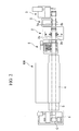
- FIGS. 1 and 2 are a front view and a plan view showing the structure of a recoiling facility 100 for magnesium alloy sheets in the present embodiment.
- this recoiling facility 100 is provided with an unwinder 1, a trimmer 2, a winder 3, a heating furnace 4, a scrap borer 5, and a leveler 6.
- a coil material C is manufactured by the hot rolling of a magnesium alloy plate, and by winding the resulting elongated magnesium alloy sheet S onto a fixed mandrel.
- the unwinder 1 is provided with a supporting portion that supports both ends of the fixed mandrel such that they are able to rotate freely, and with a drive source that causes the fixed mandrel to rotate in the unwinding direction of the magnesium alloy sheet S, and holds the aforementioned coil material C so as to be able to unwind it when needed.
- the trimmer 2 is provided with a pair of side cutters 2a and 2b which face each other at a predetermined spacing, and trims both width edges of a magnesium alloy sheet S which has been unwound from the coil material C by the unwinder 1. As a result, portions where cracks have occurred and shape defect portions are removed from the two width edges of the magnesium alloy sheet S, and the magnesium alloy sheet S is finished to a predetermined width dimension.
- the winder 3 receives the magnesium alloy sheet S after it has been trimmed by the trimmer 2 which is wound onto it without a core being used.
- the heating furnace 4 is located between the unwinder 1 and the trimmer 2, and is formed by heaters H and a table 4a inside a housing 40 with the heaters H being provided in a bottom portion thereof.
- the housing 40 is provided with an entry side shutter 41, an exit side shutter 42, apertures 43 and 44, and transporting auxiliary rollers 45 and 46.
- the aperture 43 is the intake aperture for the magnesium alloy sheet S and is formed in the upstream side surface of the housing 40
- the aperture 44 is the discharge aperture for the magnesium alloy sheet S and is formed in the downstream side surface of the housing 40.
- the entry side shutter 41 opens and closes the upstream side aperture 43 of the housing 40.
- the exit side shutter 42 opens and closes the downstream side aperture 44 of the housing 40.
- the transporting auxiliary rollers 45 and 46 are rotated by a drive source such as a motor (not shown), and assist in the coil transporting by either drawing the magnesium alloy sheet S inside the heating furnace 4 or extracting it to the outside of the furnace.
- the heaters H heat the interior of the housing 40 to a predetermined temperature (approximately 200°C) and then maintain this temperature. From the start of the heating until the interior of the housing 40 reaches the predetermined temperature, the entry side shutter 41 and the exit side shutter 42 are closed.
- the table 4a is a metal plate having a smooth top surface, and is heated by heat generating bodies located in a block beneath it. The table 4a allows a magnesium alloy sheet S to move smoothly over this smooth top surface.
- This heating furnace 4 heats a magnesium alloy sheet S to a predetermined temperature so as to soften it to a suitable degree and simplify handling including processing such as the above described trimming and the like. For example, it is possible to prevent the occurrence of defects such as unforeseen fractures being generated in the magnesium alloy sheet S from impact received during the trimming.
- the scrap borer 5 is located on the downstream side of the trimmer 2 and the upstream side of the winder 3. Scrap which is generated by the above described trimming (i.e., portions which are cut off from both side edges of the magnesium alloy sheet S) is wound onto the scrap borer 5. Because this scrap is generated from both sides of the magnesium alloy sheet S, wind-on portions 5a and 5b of the scrap borer 5 are provided on both sides of the transporting path of the magnesium alloy sheet S.
- the leveler 6 is located between the unwinder 1 and the trimmer 2 on the downstream side of the heating furnace 4. As a result of the magnesium alloy sheet S passing between a plurality of rollers 6a which are arranged in a zig-zag pattern when viewed in cross-section, any shape defect portions or any distortion in the magnesium alloy sheet S which has been generated due to the magnesium alloy sheet S being left rolled in a coil shape are corrected using warmth. Because the leveler 6 is located on the downstream side of the heating furnace 4, it straightens the magnesium alloy sheet S which has been heated in the heating furnace 4 and softened to a suitable degree. As a result, there is no occurrence of fractures and the like and superior leveling can be preformed.
- this recoiling facility 100 performs the following operations. Firstly, an operator preheats the heating furnace 4 to a predetermined temperature. At this time, the entry side shutter 41 and the exit side shutter 42 are closed. Next, the operator loads a coil material C formed by winding a magnesium alloy sheet S onto a mandrel in the unwinder 1. The unwinder 1 unwinds the magnesium alloy sheet S from the coil material C.
- the operator raises the shutters 41 and 42 as far as necessary, so as to open the upstream side and the downstream side of the heating furnace 4 in a slit shape.
- the operator inserts the front end of the magnesium alloy sheet S which has been unwound from the coil material C into the heating furnace 4 via the aforementioned slit.
- the magnesium alloy sheet S which has been inserted inside the heating furnace 4 is supported by the table 4a, and a distal end portion thereof slides over the table 4a as it is moved through the interior of the furnace.
- the magnesium alloy sheet S is then moved to the outside of the heating furnace 4.
- the magnesium alloy sheet S is heated to a predetermined temperature (approximately 200°C) as it is being transported through the interior of the heating furnace 4.
- the operator sets the magnesium alloy sheet S in the leveler 6.
- the leveler 6 corrects any shape defects or distortion in the magnesium alloy sheet S which has been heated in the heating furnace 4 and flattens the magnesium alloy sheet S. At this time, because the magnesium alloy sheet S has been softened to a suitable degree by heat, there is no occurrence of faults such as fractures being generated in the magnesium alloy sheet S caused by the leveling by the leveler 6.
- the operator sets the magnesium alloy sheet S in the trimmer 2.
- the trimmer 2 trims both width edges of the magnesium alloy sheet S so as to shape the magnesium alloy sheet S to a predetermined width, and so as to also remove any portions where cracks or shape defects or the like have been generated in the two width edges of the magnesium alloy sheet S.
- the magnesium alloy sheet S has been softened to a suitable degree by the heat and is in a warm state, there is no occurrence of faults such as fractures being generated in the magnesium alloy sheet S caused by the trimming by the trimmer 2.
- the two side edges of the magnesium alloy sheet S which have been trimmed by the trimmer 2 are discharged as elongated belt-shaped scrap.
- the operator sets the front end of the scrap discharged from the trimmer 2 in the scrap borer 5 which is located on the downstream side of the trimmer 2.
- the scrap borer 5 receives from beneath the magnesium alloy sheet S both side portions thereof which are wound onto it from above. As a result, it is possible to prevent the magnesium alloy sheet S being damaged by scrap after it has been shaped.
- the operator sets the magnesium alloy sheet 2 in the winder 3. At this time, the operator rolls a predetermined length of the magnesium alloy sheet S into a cylindrical shape when setting it, so that the magnesium alloy sheet S is wound onto the winder 3 without a core being used.
- a magnesium alloy sheet S is rewound without a mandrel being required, and both side edges thereof can be trimmed and shaped. Because the magnesium alloy sheet S is worked after having been softened to a suitable degree by being heated in the heating furnace 4, it is possible to prevent the occurrence of faults such as unforeseen cracks being generated in the magnesium alloy sheet S. Accordingly, it is possible to maintain a superior product quality.
- the heaters H may be arranged in a layout different from that shown in FIG. 1 provided that they are still able to heat the magnesium alloy sheet S to a predetermined temperature.
- the heating furnace 4 it is not necessary for the heating furnace 4 to be constructed such that the magnesium alloy sheet S is able to move smoothly over the table 4a as in the above described embodiment, and it is also possible, for example, for a plurality of transporting rollers which are arranged in parallel with each other to be driven to rotate by a drive source such as a motor or the like so that they transport the magnesium alloy sheet S.
- a manufactured magnesium alloy sheet does not require a mandrel, and it is possible to prevent the occurrence of cracks in the sheet and maintain a superior product quality.
Landscapes
- Engineering & Computer Science (AREA)
- Mechanical Engineering (AREA)
- Winding, Rewinding, Material Storage Devices (AREA)
- Straightening Metal Sheet-Like Bodies (AREA)
Abstract
Description
- The present invention relates to a recoiling facility for magnesium alloy sheets.
Priority is claimed on Japanese Patent Application No.2007-269059, filed October 16, 2007 - In the majority of lightweight metal sheets which undergo multi-pass rolling, there are many cases of cracks occurring in both width edges or of shape defects occurring therein. When this type of lightweight metal sheet is shipped as a product, the two width edges thereof are trimmed so that the sheets are shaped to a predetermined width. In addition, this trimming removes crack portions and shape defect portions so that the sheets are in a state that allows them to be shipped as products.
Conventional examples of apparatuses that perform the above described processing are disclosed, for example, in the following patent documents 1 to 4. - Patent document 1 discloses a scrap borer that enables the structure of the facility to be simplified, and enables manufacturing costs and maintenance and administration costs to be reduced.
Patent document 2 discloses a steel belt finishing facility equipped with side trimmers which makes it possible to achieve a reduction in equipment costs, and a shortening of the cycle time, and that makes it possible to prevent trimming defects.
Patent document 3 discloses a side trimmer apparatus that is able to perform side trimming processing on metal plates stably without generating any trimming defects.
Patent document 4 discloses a side trimmer apparatus for metal belts that is able to reliably prevent trimming scrap being scattered about and that is able to perform the side trimming of lightweight materials rapidly and stably even in non-steady portions such as locations where the trim width on one side becomes extremely narrow or locations where edge fractures are present. - These elongated lightweight metal sheets are wound into a cylindrical shape so as to form a coil material, however, shape defects and coil memory caused by this winding are often generated in this type of coiled lightweight metal sheet. In order to repair these shape defects and coil memory, for example, a leveler is used.
A conventional example of a leveler is disclosed in Patent document 5 (see below). The leveler disclosed inPatent document 5 is used to perform shape correction on thin plate-shaped bar materials and to remove residual stress, however, it does not heat up a material and then perform leveling on this material while it is in a warm state. - [Patent document 1] Japanese Patent Application Laid-Open (JP-A) No.
H10-43931 - [Patent document 2] Japanese Patent Application Laid-Open (JP-A) No.
2002-28703 - [Patent document 3] Japanese Patent Application Laid-Open (JP-A) No.
2000-225512 - [Patent document 4] Japanese Patent Application Laid-Open (JP-A) No.
2007-118118 - [Patent document 5] Japanese Patent Application Laid-Open (JP-A) No.
H6-77375 - Elongated lightweight metal sheets which are reverse rolled in either a hot or warm state are commonly wound onto a metal mandrel (i.e., core material) having a uniform internal diameter so as to form a coil material. Accordingly, when they are shipped in the form of a coil material equipped with a fixed mandrel, because the fixed mandrel is not required after the lightweight metal sheet has been used up, it is necessary to either dispose of the fixed mandrels or return them to the shipper or the like which uses up time and labor. Accordingly, it is desirable for a coil material to be rewound and shipped without a fixed mandrel having to be used.
Moreover, when the lightweight metal sheet is a magnesium alloy, if the magnesium alloy is trimmed at room temperature it is easy for defects to occur such as the generation of minute cracks. - However, the conventional apparatuses disclosed in the above described patent documents give no consideration to the fact that magnesium alloy cracks easily at room temperature.
- The present invention was conceived in view of the above described circumstances and it is an object thereof to manufacture a high quality product coil by rewinding a coil material which has been formed by winding a magnesium alloy sheet onto a fixed mandrel so that any further need for the fixed mandrel is eliminated, and by trimming shape defect portions and crack portions in the plate width end portions which are generated by multi-pass rolling.
- In order to solve the above described problems, the following apparatuses and methods are employed in the present invention.
As a first aspects of the present invention, a recoiling facility for a magnesium alloy sheet is employed which includes: an unwinder which is able to unwind a coil material formed by winding magnesium alloy onto a fixed mandrel; a heating furnace which is located on the downstream side of the unwinder and which heats the magnesium alloy sheet which has been unwound from the coil material to a predetermined temperature; a trimmer which is located on the downstream side of the heating furnace and which trims both side edges of the magnesium alloy sheet; and a winder which is located on the downstream side of the trimmer and which rewinds the magnesium alloy sheet. - In the recoiling facility for a magnesium alloy sheet according to the above described first aspects of the present invention, it is also possible for there to be further provided a scrap borer which is located on the downstream side of the trimmer and on the upstream side of the winder, and onto which is wound scrap trimmed from the two side edges of the magnesium alloy sheet.
- Furthermore, in the recoiling facility for a magnesium alloy sheet according to the above described first aspects of the present invention, it is also possible for there to be further provided a leveler which is located on the downstream side of the heating furnace and on the upstream side of the trimmer, and which corrects any shape defects in the magnesium alloy sheet.
- In addition, in the recoiling facility for a magnesium alloy sheet according to the above described first aspects of the present invention, it is also possible for the winder to rewind the magnesium alloy sheet without using a fixed mandrel.
- According to the present invention, because a magnesium alloy sheet is trimmed while it is heated to a predetermined temperature, it is possible to prevent cracks being generated in the magnesium alloy sheet and to maintain a superior product quality.
-
- [
FIG. 1] FIG. 1 is a front view showing the structure of a recoiling facility for magnesium alloy sheets in an embodiment of the present invention. - [
FIG. 2] FIG. 2 is a plan view showing the structure of the above recoiling facility for magnesium alloy sheets. -
- 100 ...
- Recoiling facility
- 1 ...
- Unwinder
- 2 ...
- Trimmer
- 3 ...
- Winder
- 4 ...
- Heating furnace
- 5 ...
- Scrap borer
- 6 ...
- Leveler
- C ...
- Coil material
- S ...
- Magnesium alloy sheet
- An embodiment of the present invention will now be described with reference made to the drawings.
FIGS. 1 and2 are a front view and a plan view showing the structure of arecoiling facility 100 for magnesium alloy sheets in the present embodiment.
As is shown inFIGS. 1 and2 , thisrecoiling facility 100 is provided with an unwinder 1, a trimmer 2, awinder 3, a heating furnace 4, ascrap borer 5, and a leveler 6. - Firstly, a coil material C is manufactured by the hot rolling of a magnesium alloy plate, and by winding the resulting elongated magnesium alloy sheet S onto a fixed mandrel.
The unwinder 1 is provided with a supporting portion that supports both ends of the fixed mandrel such that they are able to rotate freely, and with a drive source that causes the fixed mandrel to rotate in the unwinding direction of the magnesium alloy sheet S, and holds the aforementioned coil material C so as to be able to unwind it when needed. - The trimmer 2 is provided with a pair of
side cutters - The
winder 3 receives the magnesium alloy sheet S after it has been trimmed by the trimmer 2 which is wound onto it without a core being used. - The heating furnace 4 is located between the unwinder 1 and the trimmer 2, and is formed by heaters H and a table 4a inside a
housing 40 with the heaters H being provided in a bottom portion thereof.
Thehousing 40 is provided with anentry side shutter 41, anexit side shutter 42,apertures auxiliary rollers - The
aperture 43 is the intake aperture for the magnesium alloy sheet S and is formed in the upstream side surface of thehousing 40, while theaperture 44 is the discharge aperture for the magnesium alloy sheet S and is formed in the downstream side surface of thehousing 40.
Theentry side shutter 41 opens and closes theupstream side aperture 43 of thehousing 40. Theexit side shutter 42 opens and closes thedownstream side aperture 44 of thehousing 40.
The transportingauxiliary rollers - The heaters H heat the interior of the
housing 40 to a predetermined temperature (approximately 200°C) and then maintain this temperature. From the start of the heating until the interior of thehousing 40 reaches the predetermined temperature, theentry side shutter 41 and theexit side shutter 42 are closed.
The table 4a is a metal plate having a smooth top surface, and is heated by heat generating bodies located in a block beneath it. The table 4a allows a magnesium alloy sheet S to move smoothly over this smooth top surface. - This heating furnace 4 heats a magnesium alloy sheet S to a predetermined temperature so as to soften it to a suitable degree and simplify handling including processing such as the above described trimming and the like. For example, it is possible to prevent the occurrence of defects such as unforeseen fractures being generated in the magnesium alloy sheet S from impact received during the trimming.
- The
scrap borer 5 is located on the downstream side of the trimmer 2 and the upstream side of thewinder 3. Scrap which is generated by the above described trimming (i.e., portions which are cut off from both side edges of the magnesium alloy sheet S) is wound onto thescrap borer 5. Because this scrap is generated from both sides of the magnesium alloy sheet S, wind-onportions 5a and 5b of thescrap borer 5 are provided on both sides of the transporting path of the magnesium alloy sheet S. - The leveler 6 is located between the unwinder 1 and the trimmer 2 on the downstream side of the heating furnace 4. As a result of the magnesium alloy sheet S passing between a plurality of
rollers 6a which are arranged in a zig-zag pattern when viewed in cross-section, any shape defect portions or any distortion in the magnesium alloy sheet S which has been generated due to the magnesium alloy sheet S being left rolled in a coil shape are corrected using warmth.
Because the leveler 6 is located on the downstream side of the heating furnace 4, it straightens the magnesium alloy sheet S which has been heated in the heating furnace 4 and softened to a suitable degree. As a result, there is no occurrence of fractures and the like and superior leveling can be preformed. - Using this type of structure this
recoiling facility 100 performs the following operations.
Firstly, an operator preheats the heating furnace 4 to a predetermined temperature. At this time, theentry side shutter 41 and theexit side shutter 42 are closed.
Next, the operator loads a coil material C formed by winding a magnesium alloy sheet S onto a mandrel in the unwinder 1. The unwinder 1 unwinds the magnesium alloy sheet S from the coil material C. - Next, the operator raises the
shutters
Next, the operator inserts the front end of the magnesium alloy sheet S which has been unwound from the coil material C into the heating furnace 4 via the aforementioned slit.
The magnesium alloy sheet S which has been inserted inside the heating furnace 4 is supported by the table 4a, and a distal end portion thereof slides over the table 4a as it is moved through the interior of the furnace. The magnesium alloy sheet S is then moved to the outside of the heating furnace 4.
The magnesium alloy sheet S is heated to a predetermined temperature (approximately 200°C) as it is being transported through the interior of the heating furnace 4. - When the front end of the magnesium alloy sheet S exits from the downstream side slit in the heating furnace 4, the operator sets the magnesium alloy sheet S in the leveler 6.
The leveler 6 corrects any shape defects or distortion in the magnesium alloy sheet S which has been heated in the heating furnace 4 and flattens the magnesium alloy sheet S. At this time, because the magnesium alloy sheet S has been softened to a suitable degree by heat, there is no occurrence of faults such as fractures being generated in the magnesium alloy sheet S caused by the leveling by the leveler 6. - When the front end of the magnesium alloy sheet S exits from the leveler 6, the operator sets the magnesium alloy sheet S in the trimmer 2.
The trimmer 2 trims both width edges of the magnesium alloy sheet S so as to shape the magnesium alloy sheet S to a predetermined width, and so as to also remove any portions where cracks or shape defects or the like have been generated in the two width edges of the magnesium alloy sheet S. At this time as well, because the magnesium alloy sheet S has been softened to a suitable degree by the heat and is in a warm state, there is no occurrence of faults such as fractures being generated in the magnesium alloy sheet S caused by the trimming by the trimmer 2. - The two side edges of the magnesium alloy sheet S which have been trimmed by the trimmer 2 are discharged as elongated belt-shaped scrap.
The operator sets the front end of the scrap discharged from the trimmer 2 in thescrap borer 5 which is located on the downstream side of the trimmer 2.
Thescrap borer 5 receives from beneath the magnesium alloy sheet S both side portions thereof which are wound onto it from above. As a result, it is possible to prevent the magnesium alloy sheet S being damaged by scrap after it has been shaped. - When the front end of the magnesium alloy sheet S which has been shaped to a predetermined width exits from the trimmer 2, the operator sets the magnesium alloy sheet 2 in the
winder 3. At this time, the operator rolls a predetermined length of the magnesium alloy sheet S into a cylindrical shape when setting it, so that the magnesium alloy sheet S is wound onto thewinder 3 without a core being used. - In this manner, according to the present embodiment, a magnesium alloy sheet S is rewound without a mandrel being required, and both side edges thereof can be trimmed and shaped. Because the magnesium alloy sheet S is worked after having been softened to a suitable degree by being heated in the heating furnace 4, it is possible to prevent the occurrence of faults such as unforeseen cracks being generated in the magnesium alloy sheet S. Accordingly, it is possible to maintain a superior product quality.
- Note that the above described embodiment is only an example and in no way limits the present invention. Various modifications can be made to the embodiment insofar as they do not depart from the spirit or scope of the present invention.
- For example, the heaters H may be arranged in a layout different from that shown in
FIG. 1 provided that they are still able to heat the magnesium alloy sheet S to a predetermined temperature. - Moreover, it is not necessary for the heating furnace 4 to be constructed such that the magnesium alloy sheet S is able to move smoothly over the table 4a as in the above described embodiment, and it is also possible, for example, for a plurality of transporting rollers which are arranged in parallel with each other to be driven to rotate by a drive source such as a motor or the like so that they transport the magnesium alloy sheet S.
- According to the recoiling facility for a magnesium alloy sheet of the present invention, a manufactured magnesium alloy sheet does not require a mandrel, and it is possible to prevent the occurrence of cracks in the sheet and maintain a superior product quality.
Claims (4)
- A recoiling facility for a magnesium alloy sheet comprising:an unwinder which is able to unwind a coil material formed by winding magnesium alloy onto a fixed mandrel;a heating furnace which is located on the downstream side of the unwinder and which heats the magnesium alloy sheet which has been unwound from the coil material to a predetermined temperature;a trimmer which is located on the downstream side of the heating furnace and which trims both side edges of the magnesium alloy sheet; anda winder which is located on the downstream side of the trimmer and which rewinds the magnesium alloy sheet.
- The recoiling facility for a magnesium alloy sheet according to claim 1, wherein there is further provided a scrap borer which is located on the downstream side of the trimmer and on the upstream side of the winder, and onto which is wound scrap trimmed from the two side edges of the magnesium alloy sheet.
- The recoiling facility for a magnesium alloy sheet according to claim 1 or 2, wherein there is further provided a leveler which is located on the downstream side of the heating furnace and on the upstream side of the trimmer, and which corrects any shape defects in the magnesium alloy sheet.
- The recoiling facility for a magnesium alloy sheet according to any one of claims 1 through 3, wherein the winder rewinds the magnesium alloy sheet without using a fixed mandrel.
Applications Claiming Priority (2)
| Application Number | Priority Date | Filing Date | Title |
|---|---|---|---|
| JP2007269059A JP5238211B6 (en) | 2007-10-16 | Magnesium alloy sheet recoiling equipment | |
| PCT/JP2008/068747 WO2009051177A1 (en) | 2007-10-16 | 2008-10-16 | Recoiling facility of magnesium alloy sheet |
Publications (3)
| Publication Number | Publication Date |
|---|---|
| EP2210679A1 true EP2210679A1 (en) | 2010-07-28 |
| EP2210679A4 EP2210679A4 (en) | 2011-11-09 |
| EP2210679B1 EP2210679B1 (en) | 2012-09-12 |
Family
ID=40567439
Family Applications (1)
| Application Number | Title | Priority Date | Filing Date |
|---|---|---|---|
| EP08840702A Not-in-force EP2210679B1 (en) | 2007-10-16 | 2008-10-16 | Recoiling facility of magnesium alloy sheet |
Country Status (8)
| Country | Link |
|---|---|
| US (1) | US20110095125A1 (en) |
| EP (1) | EP2210679B1 (en) |
| KR (1) | KR20100060023A (en) |
| CN (2) | CN103949493B (en) |
| CA (1) | CA2702733A1 (en) |
| RU (1) | RU2443487C2 (en) |
| TW (1) | TWI389747B (en) |
| WO (1) | WO2009051177A1 (en) |
Cited By (1)
| Publication number | Priority date | Publication date | Assignee | Title |
|---|---|---|---|---|
| CN102059394A (en) * | 2010-12-01 | 2011-05-18 | 河南东力重工机械有限公司 | Numerical control metal plate dividing and shearing device |
Families Citing this family (5)
| Publication number | Priority date | Publication date | Assignee | Title |
|---|---|---|---|---|
| CN105149377B (en) * | 2015-09-30 | 2017-06-30 | 中镁镁业有限公司 | The online hot air heating apparatus of magnesium alloy extrusion plate and heating method for coiling |
| CN108495724B (en) * | 2016-09-27 | 2020-01-31 | 诺维尔里斯公司 | System and method for threading metal substrates onto rolling mills |
| JP6921944B2 (en) | 2016-09-27 | 2021-08-18 | ノベリス・インコーポレイテッドNovelis Inc. | Rotating magnet heat induction |
| CN108471647A (en) * | 2018-03-29 | 2018-08-31 | 苏州雪牛商贸有限公司 | A kind of heating device for magnesium alloy |
| CN117798796A (en) * | 2024-02-29 | 2024-04-02 | 江苏浩帮重钢制造有限公司 | A kind of grinding wheel cutting machine for steel structure parts processing and method thereof |
Family Cites Families (12)
| Publication number | Priority date | Publication date | Assignee | Title |
|---|---|---|---|---|
| US4019359A (en) * | 1974-05-06 | 1977-04-26 | The Steel Company Of Canada, Limited | Method of hot rolling metal strip |
| GB1507827A (en) * | 1974-05-06 | 1978-04-19 | Canada Steel Co | Handling rolled transfer bars |
| JPS61135420A (en) * | 1984-12-06 | 1986-06-23 | Kawasaki Steel Corp | Treatment of hot rolled strip |
| DE4423664A1 (en) * | 1994-07-07 | 1996-05-15 | Bwg Bergwerk Walzwerk | Process for producing cold-rolled steel strips from stainless steel and metal strips, in particular from titanium alloys |
| JPH09225518A (en) * | 1996-02-20 | 1997-09-02 | Ishikawajima Harima Heavy Ind Co Ltd | Coil end face heating device |
| JPH1043931A (en) * | 1996-08-05 | 1998-02-17 | Mitsubishi Heavy Ind Ltd | Scrap borer and method for winding scrap |
| JP4278256B2 (en) * | 2000-01-06 | 2009-06-10 | 日本金属株式会社 | Warm plastic working method |
| JP3521863B2 (en) * | 2000-10-24 | 2004-04-26 | 住友金属工業株式会社 | Manufacturing method of magnesium alloy sheet |
| RU2215599C1 (en) * | 2002-04-08 | 2003-11-10 | Закрытое акционерное общество "Промышленный центр "МАТЭКС" | Method for making sheets and plates of magnesium alloys |
| DE10234109A1 (en) * | 2002-07-26 | 2004-02-05 | Sms Demag Ag | Method and device for the continuous production of metallic strips |
| JP2005105358A (en) * | 2003-09-30 | 2005-04-21 | Jfe Steel Kk | Hot-rolled steel sheet processing line and high-strength hot-rolled steel sheet manufacturing method |
| CN100393463C (en) * | 2006-05-23 | 2008-06-11 | 西南铝业(集团)有限责任公司 | Production device and production method of aluminum sheet shearing and coiling |
-
2008
- 2008-10-14 TW TW097139315A patent/TWI389747B/en not_active IP Right Cessation
- 2008-10-16 RU RU2010118483/02A patent/RU2443487C2/en not_active IP Right Cessation
- 2008-10-16 CN CN201410149702.6A patent/CN103949493B/en not_active Expired - Fee Related
- 2008-10-16 KR KR1020107009393A patent/KR20100060023A/en not_active Ceased
- 2008-10-16 EP EP08840702A patent/EP2210679B1/en not_active Not-in-force
- 2008-10-16 CN CN200880112337A patent/CN101821031A/en active Pending
- 2008-10-16 WO PCT/JP2008/068747 patent/WO2009051177A1/en not_active Ceased
- 2008-10-16 US US12/682,803 patent/US20110095125A1/en not_active Abandoned
- 2008-10-16 CA CA2702733A patent/CA2702733A1/en not_active Abandoned
Non-Patent Citations (2)
| Title |
|---|
| No further relevant documents disclosed * |
| See also references of WO2009051177A1 * |
Cited By (1)
| Publication number | Priority date | Publication date | Assignee | Title |
|---|---|---|---|---|
| CN102059394A (en) * | 2010-12-01 | 2011-05-18 | 河南东力重工机械有限公司 | Numerical control metal plate dividing and shearing device |
Also Published As
| Publication number | Publication date |
|---|---|
| TW200936265A (en) | 2009-09-01 |
| JP2009095850A (en) | 2009-05-07 |
| TWI389747B (en) | 2013-03-21 |
| CA2702733A1 (en) | 2009-04-23 |
| JP5238211B2 (en) | 2013-07-17 |
| CN101821031A (en) | 2010-09-01 |
| RU2443487C2 (en) | 2012-02-27 |
| WO2009051177A1 (en) | 2009-04-23 |
| US20110095125A1 (en) | 2011-04-28 |
| EP2210679B1 (en) | 2012-09-12 |
| KR20100060023A (en) | 2010-06-04 |
| EP2210679A4 (en) | 2011-11-09 |
| RU2010118483A (en) | 2011-11-27 |
| CN103949493A (en) | 2014-07-30 |
| CN103949493B (en) | 2016-03-09 |
Similar Documents
| Publication | Publication Date | Title |
|---|---|---|
| EP2210679B1 (en) | Recoiling facility of magnesium alloy sheet | |
| EP2213387B1 (en) | Magnesium alloy hot-rolling mill | |
| JP2013516320A (en) | Winding / unwinding device and method for winding / unwinding metal product in rolling line | |
| JP2011088206A (en) | Hot-rolling apparatus for magnesium alloy thin sheet | |
| JP2011088205A (en) | Apparatus for manufacturing magnesium alloy sheet | |
| CN101821025B (en) | Magnesium alloy hot-rolling mill | |
| KR20210115951A (en) | Side guide for steel plate slitting and cutting machine | |
| JP5238211B6 (en) | Magnesium alloy sheet recoiling equipment | |
| TWI628008B (en) | Hot-rolled steel sheet and manufacturing method thereof | |
| KR20090065653A (en) | Tip guide device of STS cold rolled coil | |
| JP3428400B2 (en) | Hot rolling equipment and hot rolling method | |
| EP2937154A1 (en) | Mandrel of coil box | |
| KR101536458B1 (en) | Apparatus and Method for manufacturing of strip | |
| JP2021164936A (en) | Cold-rolled steel strip manufacturing equipment and cold-rolled steel strip manufacturing method | |
| DE112021000508T5 (en) | METHOD FOR MAKING GLASS FILM AND APPARATUS FOR MAKING GLASS FILM | |
| JPH09225518A (en) | Coil end face heating device | |
| JPH10137844A (en) | Steckel mill rolling equipment | |
| KR20100045382A (en) | Cutting device | |
| JPH08103805A (en) | Steel cutting method with flying crop shear | |
| JP5173347B6 (en) | Magnesium alloy hot rolling method and magnesium alloy hot rolling apparatus | |
| JPH08309403A (en) | Continuous hot rolling method for multiple plate materials | |
| KR20200127401A (en) | Apparatus for banding steel coil and method of banding steel coil | |
| JPH06108162A (en) | Coil deformation prevention device | |
| MXPA99010934A (en) | Reversible finisher laminating apparatus | |
| CZ286384B6 (en) | Method of winding-up thin and narrow metal bands and apparatus for making the same |
Legal Events
| Date | Code | Title | Description |
|---|---|---|---|
| PUAI | Public reference made under article 153(3) epc to a published international application that has entered the european phase |
Free format text: ORIGINAL CODE: 0009012 |
|
| 17P | Request for examination filed |
Effective date: 20100510 |
|
| AK | Designated contracting states |
Kind code of ref document: A1 Designated state(s): AT BE BG CH CY CZ DE DK EE ES FI FR GB GR HR HU IE IS IT LI LT LU LV MC MT NL NO PL PT RO SE SI SK TR |
|
| AX | Request for extension of the european patent |
Extension state: AL BA MK RS |
|
| DAX | Request for extension of the european patent (deleted) | ||
| A4 | Supplementary search report drawn up and despatched |
Effective date: 20111007 |
|
| RIC1 | Information provided on ipc code assigned before grant |
Ipc: B21C 47/18 20060101ALI20111004BHEP Ipc: B21C 47/08 20060101ALI20111004BHEP Ipc: B21C 47/26 20060101AFI20111004BHEP |
|
| REG | Reference to a national code |
Ref country code: DE Ref legal event code: R079 Ref document number: 602008018781 Country of ref document: DE Free format text: PREVIOUS MAIN CLASS: B21C0047260000 Ipc: B21C0047040000 |
|
| GRAP | Despatch of communication of intention to grant a patent |
Free format text: ORIGINAL CODE: EPIDOSNIGR1 |
|
| RIC1 | Information provided on ipc code assigned before grant |
Ipc: B21C 47/26 20060101ALI20120229BHEP Ipc: B23D 19/06 20060101ALI20120229BHEP Ipc: B21C 47/18 20060101ALI20120229BHEP Ipc: B21C 47/04 20060101AFI20120229BHEP |
|
| RIN1 | Information on inventor provided before grant (corrected) |
Inventor name: TAZOE, NOBUHIRO Inventor name: HONJOU, HISASHI Inventor name: MATSUMURA, HIDEO Inventor name: YANAI, FUMITAKA Inventor name: YANAI, KATUHIKO |
|
| GRAS | Grant fee paid |
Free format text: ORIGINAL CODE: EPIDOSNIGR3 |
|
| GRAA | (expected) grant |
Free format text: ORIGINAL CODE: 0009210 |
|
| AK | Designated contracting states |
Kind code of ref document: B1 Designated state(s): AT BE BG CH CY CZ DE DK EE ES FI FR GB GR HR HU IE IS IT LI LT LU LV MC MT NL NO PL PT RO SE SI SK TR |
|
| REG | Reference to a national code |
Ref country code: GB Ref legal event code: FG4D |
|
| REG | Reference to a national code |
Ref country code: CH Ref legal event code: EP |
|
| REG | Reference to a national code |
Ref country code: AT Ref legal event code: REF Ref document number: 574809 Country of ref document: AT Kind code of ref document: T Effective date: 20120915 |
|
| REG | Reference to a national code |
Ref country code: IE Ref legal event code: FG4D |
|
| REG | Reference to a national code |
Ref country code: DE Ref legal event code: R096 Ref document number: 602008018781 Country of ref document: DE Effective date: 20121108 |
|
| PG25 | Lapsed in a contracting state [announced via postgrant information from national office to epo] |
Ref country code: CY Free format text: LAPSE BECAUSE OF FAILURE TO SUBMIT A TRANSLATION OF THE DESCRIPTION OR TO PAY THE FEE WITHIN THE PRESCRIBED TIME-LIMIT Effective date: 20120912 Ref country code: FI Free format text: LAPSE BECAUSE OF FAILURE TO SUBMIT A TRANSLATION OF THE DESCRIPTION OR TO PAY THE FEE WITHIN THE PRESCRIBED TIME-LIMIT Effective date: 20120912 Ref country code: HR Free format text: LAPSE BECAUSE OF FAILURE TO SUBMIT A TRANSLATION OF THE DESCRIPTION OR TO PAY THE FEE WITHIN THE PRESCRIBED TIME-LIMIT Effective date: 20120912 Ref country code: NO Free format text: LAPSE BECAUSE OF FAILURE TO SUBMIT A TRANSLATION OF THE DESCRIPTION OR TO PAY THE FEE WITHIN THE PRESCRIBED TIME-LIMIT Effective date: 20121212 Ref country code: LT Free format text: LAPSE BECAUSE OF FAILURE TO SUBMIT A TRANSLATION OF THE DESCRIPTION OR TO PAY THE FEE WITHIN THE PRESCRIBED TIME-LIMIT Effective date: 20120912 |
|
| REG | Reference to a national code |
Ref country code: NL Ref legal event code: VDEP Effective date: 20120912 |
|
| REG | Reference to a national code |
Ref country code: AT Ref legal event code: MK05 Ref document number: 574809 Country of ref document: AT Kind code of ref document: T Effective date: 20120912 |
|
| REG | Reference to a national code |
Ref country code: LT Ref legal event code: MG4D Effective date: 20120912 |
|
| PG25 | Lapsed in a contracting state [announced via postgrant information from national office to epo] |
Ref country code: SE Free format text: LAPSE BECAUSE OF FAILURE TO SUBMIT A TRANSLATION OF THE DESCRIPTION OR TO PAY THE FEE WITHIN THE PRESCRIBED TIME-LIMIT Effective date: 20120912 Ref country code: LV Free format text: LAPSE BECAUSE OF FAILURE TO SUBMIT A TRANSLATION OF THE DESCRIPTION OR TO PAY THE FEE WITHIN THE PRESCRIBED TIME-LIMIT Effective date: 20120912 Ref country code: SI Free format text: LAPSE BECAUSE OF FAILURE TO SUBMIT A TRANSLATION OF THE DESCRIPTION OR TO PAY THE FEE WITHIN THE PRESCRIBED TIME-LIMIT Effective date: 20120912 Ref country code: GR Free format text: LAPSE BECAUSE OF FAILURE TO SUBMIT A TRANSLATION OF THE DESCRIPTION OR TO PAY THE FEE WITHIN THE PRESCRIBED TIME-LIMIT Effective date: 20121213 |
|
| PG25 | Lapsed in a contracting state [announced via postgrant information from national office to epo] |
Ref country code: BE Free format text: LAPSE BECAUSE OF FAILURE TO SUBMIT A TRANSLATION OF THE DESCRIPTION OR TO PAY THE FEE WITHIN THE PRESCRIBED TIME-LIMIT Effective date: 20120912 Ref country code: IS Free format text: LAPSE BECAUSE OF FAILURE TO SUBMIT A TRANSLATION OF THE DESCRIPTION OR TO PAY THE FEE WITHIN THE PRESCRIBED TIME-LIMIT Effective date: 20130112 Ref country code: NL Free format text: LAPSE BECAUSE OF FAILURE TO SUBMIT A TRANSLATION OF THE DESCRIPTION OR TO PAY THE FEE WITHIN THE PRESCRIBED TIME-LIMIT Effective date: 20120912 Ref country code: ES Free format text: LAPSE BECAUSE OF FAILURE TO SUBMIT A TRANSLATION OF THE DESCRIPTION OR TO PAY THE FEE WITHIN THE PRESCRIBED TIME-LIMIT Effective date: 20121223 Ref country code: EE Free format text: LAPSE BECAUSE OF FAILURE TO SUBMIT A TRANSLATION OF THE DESCRIPTION OR TO PAY THE FEE WITHIN THE PRESCRIBED TIME-LIMIT Effective date: 20120912 Ref country code: RO Free format text: LAPSE BECAUSE OF FAILURE TO SUBMIT A TRANSLATION OF THE DESCRIPTION OR TO PAY THE FEE WITHIN THE PRESCRIBED TIME-LIMIT Effective date: 20120912 Ref country code: CZ Free format text: LAPSE BECAUSE OF FAILURE TO SUBMIT A TRANSLATION OF THE DESCRIPTION OR TO PAY THE FEE WITHIN THE PRESCRIBED TIME-LIMIT Effective date: 20120912 |
|
| PG25 | Lapsed in a contracting state [announced via postgrant information from national office to epo] |
Ref country code: SK Free format text: LAPSE BECAUSE OF FAILURE TO SUBMIT A TRANSLATION OF THE DESCRIPTION OR TO PAY THE FEE WITHIN THE PRESCRIBED TIME-LIMIT Effective date: 20120912 Ref country code: PT Free format text: LAPSE BECAUSE OF FAILURE TO SUBMIT A TRANSLATION OF THE DESCRIPTION OR TO PAY THE FEE WITHIN THE PRESCRIBED TIME-LIMIT Effective date: 20130114 Ref country code: PL Free format text: LAPSE BECAUSE OF FAILURE TO SUBMIT A TRANSLATION OF THE DESCRIPTION OR TO PAY THE FEE WITHIN THE PRESCRIBED TIME-LIMIT Effective date: 20120912 Ref country code: MC Free format text: LAPSE BECAUSE OF NON-PAYMENT OF DUE FEES Effective date: 20121031 |
|
| REG | Reference to a national code |
Ref country code: CH Ref legal event code: PL |
|
| PG25 | Lapsed in a contracting state [announced via postgrant information from national office to epo] |
Ref country code: AT Free format text: LAPSE BECAUSE OF FAILURE TO SUBMIT A TRANSLATION OF THE DESCRIPTION OR TO PAY THE FEE WITHIN THE PRESCRIBED TIME-LIMIT Effective date: 20120912 |
|
| REG | Reference to a national code |
Ref country code: IE Ref legal event code: MM4A |
|
| PLBE | No opposition filed within time limit |
Free format text: ORIGINAL CODE: 0009261 |
|
| STAA | Information on the status of an ep patent application or granted ep patent |
Free format text: STATUS: NO OPPOSITION FILED WITHIN TIME LIMIT |
|
| REG | Reference to a national code |
Ref country code: FR Ref legal event code: ST Effective date: 20130628 |
|
| PG25 | Lapsed in a contracting state [announced via postgrant information from national office to epo] |
Ref country code: BG Free format text: LAPSE BECAUSE OF FAILURE TO SUBMIT A TRANSLATION OF THE DESCRIPTION OR TO PAY THE FEE WITHIN THE PRESCRIBED TIME-LIMIT Effective date: 20121212 Ref country code: IE Free format text: LAPSE BECAUSE OF NON-PAYMENT OF DUE FEES Effective date: 20121016 Ref country code: DK Free format text: LAPSE BECAUSE OF FAILURE TO SUBMIT A TRANSLATION OF THE DESCRIPTION OR TO PAY THE FEE WITHIN THE PRESCRIBED TIME-LIMIT Effective date: 20120912 Ref country code: CH Free format text: LAPSE BECAUSE OF NON-PAYMENT OF DUE FEES Effective date: 20121031 Ref country code: LI Free format text: LAPSE BECAUSE OF NON-PAYMENT OF DUE FEES Effective date: 20121031 |
|
| 26N | No opposition filed |
Effective date: 20130613 |
|
| GBPC | Gb: european patent ceased through non-payment of renewal fee |
Effective date: 20121212 |
|
| PG25 | Lapsed in a contracting state [announced via postgrant information from national office to epo] |
Ref country code: IT Free format text: LAPSE BECAUSE OF FAILURE TO SUBMIT A TRANSLATION OF THE DESCRIPTION OR TO PAY THE FEE WITHIN THE PRESCRIBED TIME-LIMIT Effective date: 20120912 Ref country code: FR Free format text: LAPSE BECAUSE OF NON-PAYMENT OF DUE FEES Effective date: 20121112 |
|
| REG | Reference to a national code |
Ref country code: DE Ref legal event code: R097 Ref document number: 602008018781 Country of ref document: DE Effective date: 20130613 |
|
| REG | Reference to a national code |
Ref country code: DE Ref legal event code: R082 Ref document number: 602008018781 Country of ref document: DE Representative=s name: MARKS & CLERK (LUXEMBOURG) LLP, LU |
|
| PG25 | Lapsed in a contracting state [announced via postgrant information from national office to epo] |
Ref country code: GB Free format text: LAPSE BECAUSE OF NON-PAYMENT OF DUE FEES Effective date: 20121212 Ref country code: MT Free format text: LAPSE BECAUSE OF FAILURE TO SUBMIT A TRANSLATION OF THE DESCRIPTION OR TO PAY THE FEE WITHIN THE PRESCRIBED TIME-LIMIT Effective date: 20120912 |
|
| REG | Reference to a national code |
Ref country code: DE Ref legal event code: R081 Ref document number: 602008018781 Country of ref document: DE Owner name: IHI CORPORATION, JP Free format text: FORMER OWNERS: IHI CORPORATION, TOKYO, JP; IHI METALTECH CO., LTD., TOKYO, JP Effective date: 20131112 Ref country code: DE Ref legal event code: R081 Ref document number: 602008018781 Country of ref document: DE Owner name: IHI CORPORATION, JP Free format text: FORMER OWNER: IHI CORPORATION, IHI METALTECH CO., LTD., , JP Effective date: 20131112 Ref country code: DE Ref legal event code: R082 Ref document number: 602008018781 Country of ref document: DE Representative=s name: MARKS & CLERK (LUXEMBOURG) LLP, LU Effective date: 20131112 |
|
| PG25 | Lapsed in a contracting state [announced via postgrant information from national office to epo] |
Ref country code: TR Free format text: LAPSE BECAUSE OF FAILURE TO SUBMIT A TRANSLATION OF THE DESCRIPTION OR TO PAY THE FEE WITHIN THE PRESCRIBED TIME-LIMIT Effective date: 20120912 |
|
| PG25 | Lapsed in a contracting state [announced via postgrant information from national office to epo] |
Ref country code: LU Free format text: LAPSE BECAUSE OF NON-PAYMENT OF DUE FEES Effective date: 20121016 |
|
| PG25 | Lapsed in a contracting state [announced via postgrant information from national office to epo] |
Ref country code: HU Free format text: LAPSE BECAUSE OF FAILURE TO SUBMIT A TRANSLATION OF THE DESCRIPTION OR TO PAY THE FEE WITHIN THE PRESCRIBED TIME-LIMIT Effective date: 20081016 |
|
| PGFP | Annual fee paid to national office [announced via postgrant information from national office to epo] |
Ref country code: DE Payment date: 20141007 Year of fee payment: 7 |
|
| REG | Reference to a national code |
Ref country code: DE Ref legal event code: R119 Ref document number: 602008018781 Country of ref document: DE |
|
| PG25 | Lapsed in a contracting state [announced via postgrant information from national office to epo] |
Ref country code: DE Free format text: LAPSE BECAUSE OF NON-PAYMENT OF DUE FEES Effective date: 20160503 |