EP2210469A1 - A seed gathering device for use by an agricultural harvester - Google Patents
A seed gathering device for use by an agricultural harvester Download PDFInfo
- Publication number
- EP2210469A1 EP2210469A1 EP09179393A EP09179393A EP2210469A1 EP 2210469 A1 EP2210469 A1 EP 2210469A1 EP 09179393 A EP09179393 A EP 09179393A EP 09179393 A EP09179393 A EP 09179393A EP 2210469 A1 EP2210469 A1 EP 2210469A1
- Authority
- EP
- European Patent Office
- Prior art keywords
- gathering
- grain
- stalk
- crop
- seed
- Prior art date
- Legal status (The legal status is an assumption and is not a legal conclusion. Google has not performed a legal analysis and makes no representation as to the accuracy of the status listed.)
- Granted
Links
- 239000000463 material Substances 0.000 claims abstract description 29
- 238000005520 cutting process Methods 0.000 claims abstract description 15
- 238000003306 harvesting Methods 0.000 claims abstract description 14
- 244000038559 crop plants Species 0.000 claims abstract description 10
- 244000138286 Sorghum saccharatum Species 0.000 description 30
- 235000011684 Sorghum saccharatum Nutrition 0.000 description 30
- 210000003128 head Anatomy 0.000 description 24
- 239000002028 Biomass Substances 0.000 description 21
- 235000013339 cereals Nutrition 0.000 description 18
- 241000209134 Arundinaria Species 0.000 description 10
- 235000015505 Sorghum bicolor subsp. bicolor Nutrition 0.000 description 10
- 238000003860 storage Methods 0.000 description 9
- 240000000111 Saccharum officinarum Species 0.000 description 8
- 235000007201 Saccharum officinarum Nutrition 0.000 description 6
- 238000004519 manufacturing process Methods 0.000 description 5
- 241000196324 Embryophyta Species 0.000 description 4
- LFQSCWFLJHTTHZ-UHFFFAOYSA-N Ethanol Chemical compound CCO LFQSCWFLJHTTHZ-UHFFFAOYSA-N 0.000 description 4
- 241001124569 Lycaenidae Species 0.000 description 4
- 241001272996 Polyphylla fullo Species 0.000 description 2
- 240000008042 Zea mays Species 0.000 description 2
- 235000005824 Zea mays ssp. parviglumis Nutrition 0.000 description 2
- 235000002017 Zea mays subsp mays Nutrition 0.000 description 2
- 235000005822 corn Nutrition 0.000 description 2
- 239000002184 metal Substances 0.000 description 2
- 238000000034 method Methods 0.000 description 2
- 239000004460 silage Substances 0.000 description 2
- 239000010902 straw Substances 0.000 description 2
- 241001494508 Arundo donax Species 0.000 description 1
- 244000025254 Cannabis sativa Species 0.000 description 1
- 244000258136 Costus speciosus Species 0.000 description 1
- 235000000385 Costus speciosus Nutrition 0.000 description 1
- 244000068988 Glycine max Species 0.000 description 1
- 235000010469 Glycine max Nutrition 0.000 description 1
- 241001465754 Metazoa Species 0.000 description 1
- 240000003433 Miscanthus floridulus Species 0.000 description 1
- 235000014676 Phragmites communis Nutrition 0.000 description 1
- 241000209504 Poaceae Species 0.000 description 1
- 244000007853 Sarothamnus scoparius Species 0.000 description 1
- 230000009286 beneficial effect Effects 0.000 description 1
- 239000004464 cereal grain Substances 0.000 description 1
- 238000004140 cleaning Methods 0.000 description 1
- 238000010276 construction Methods 0.000 description 1
- 230000003247 decreasing effect Effects 0.000 description 1
- 230000001419 dependent effect Effects 0.000 description 1
- 239000000835 fiber Substances 0.000 description 1
- 244000037666 field crops Species 0.000 description 1
- 235000013305 food Nutrition 0.000 description 1
- 239000004459 forage Substances 0.000 description 1
- 235000011389 fruit/vegetable juice Nutrition 0.000 description 1
- 244000144972 livestock Species 0.000 description 1
- 230000007774 longterm Effects 0.000 description 1
- 210000004894 snout Anatomy 0.000 description 1
- 239000006188 syrup Substances 0.000 description 1
- 235000020357 syrup Nutrition 0.000 description 1
- 244000107466 tall cane Species 0.000 description 1
Images

Classifications
-
- A—HUMAN NECESSITIES
- A01—AGRICULTURE; FORESTRY; ANIMAL HUSBANDRY; HUNTING; TRAPPING; FISHING
- A01D—HARVESTING; MOWING
- A01D45/00—Harvesting of standing crops
- A01D45/003—Harvesting of standing crops of millet, sorghum
-
- A—HUMAN NECESSITIES
- A01—AGRICULTURE; FORESTRY; ANIMAL HUSBANDRY; HUNTING; TRAPPING; FISHING
- A01D—HARVESTING; MOWING
- A01D47/00—Headers for topping of plants, e.g. stalks with ears
Definitions
- the present invention relates to agricultural harvesters, and, more particularly, to harvesters for harvesting cane or stalk-like crops.
- Sorghum is a major cereal grain that is one of the oldest known crops and is used as a staple food in many places in Africa and Asia. Sorghum is a major feed grain crop in the U.S., Mexico, Argentina, Australia, and South Africa. It is believed that sorghum was introduced into the United States in the 1700's and some believe that Benjamin Franklin introduced the first grain sorghum crop. The seed of grain sorghum is the smallest of the spring planted field crops, such as corn and soybeans.
- Sorghum is a member of the grass family that is classified into four groups, those being: grain sorghums, grass sorghums, sweet sorghums, and broomcorn.
- Broomcorn is grown for the brush or the branches of the seed cluster with the fibers thereof being used for the making of brooms.
- Sweet sorghums are grown for the production of sorghum syrup which is produced from the juices pressed from the stems that is then subsequently boiled to the proper thickness.
- Animal feed and silage can also be made from sweet sorghums.
- Grassy sorghums are grown for green feed and hay, often reaching 10 feet in height.
- Grain sorghums are grown especially for their rounded, starchy seeds.
- sorghum for the production of ethanol has brought additional emphasis to the economics of sorghum production. It is known to gather sorghum grain by utilizing a regular grain header on a combine that is utilized to cut the heads from the sorghum and then process the heads through the threshing portion of a combine.
- a row crop attachment can be utilized to help the pickup and intake of the crop.
- the row crop attachments fit in front of the grain header cutter bar and have gathering points, gathering chains, and kicker wheels like a forage harvester head. Sorghum stems often catch and choke the straw walkers of a combine causing inconvenience and lost time in the cleaning of the straw walkers.
- Grain sorghum stalks are smaller and normally wetter to harvest than corn stalks and are more likely to be chopped up and delivered into the grain tank. Pieces of stalk return to the cylinder in the tailings and can exacerbate this condition. To handle this situation the chaffer section may be covered with sheet metal to keep the stalks out of the return flow to the cylinder.
- sugar cane harvesters For the harvesting of the sorghum stalk, sugar cane harvesters can be utilized that cut the stalk into billets for transfer to a wagon for further processing.
- Sugar cane harvesters may include a top cutting tool for the cutting off of the seed portion of the sugar cane. The seed portion of the sugarcane plant is discarded in this harvesting system since it has low amounts of sugar content.
- An upper crop material gathering device is couplable to a work machine for harvesting cane crop having a chassis to which is attached a lower crop material gathering device.
- the work machine has a direction of travel.
- the upper crop material gathering device includes at least one moving device and a stalk cutting device.
- the at least one moving device is configured to substantially surround a stalk of a cane crop plant as the at least one moving device moves.
- the at least one moving device is further configured to bend the head of the cane crop plant in a direction substantially opposite to the direction of travel.
- the stalk cutting device is positioned proximate to the at least one moving device.
- the stalk cutting device is configured to cut the peduncle of the cane crop plant.
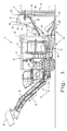
- FIGs. 1 and 2 there is shown an embodiment of an agricultural work machine in the form of a harvester 10 for a stalk-like crop 12 including both biomass crop material 14 and upper seed heads 16.
- the biomass crop material 14 may include both stalks and leaves, each of which may have value for certain applications, such as livestock feed, sugar production, ethanol production, etc.
- crop 12 is a cane crop in the form of sweet sorghum but could be a different type of crop.
- Harvester 10 generally includes a base unit 18 carrying both a biomass harvester sub-system 20 and seed harvester sub-system 22. Each of biomass harvester sub-system 20 and seed harvester sub-system 22 are carried by the frame or chassis of base unit 18, with seed harvester sub-system 22 being positioned generally above biomass harvester sub-system 20. Biomass harvester sub-system 20 is used for harvesting the biomass crop material 14, and seed harvester sub-system 22 is used for separately and independently harvesting and processing seed from seed heads 16. Seed harvester sub-system 22 is also referred to as an upper crop material gathering device 22 and biomass harvester sub-system 20 is also referred to as a lower crop material gathering device 20.
- biomass harvester sub-system 20 has a general flow path 26 of biomass crop material 14 through harvester 10 ( Fig. 1 ) which is below a general flow path 28 of seed from the seed heads 16 through seed harvester sub-system 22.
- the separate flow paths 26 and 28 allow the biomass crop material 14 and seed crop material from seed heads 16 to be separately processed and off-loaded from harvester 10.
- Biomass harvester sub-system 20 includes a biomass harvester 24 carried by base unit 18.
- the biomass harvester 24 includes a base cutter 30 which cuts the stalks of crop 12 near ground level.
- the biomass harvester sub-system 20 further includes a set of feed rollers 32, chopper unit 34, temporary storage bin 36 (also referred to as an "elevator basket"), elevator 38 and secondary extractor 40.
- feed rollers 32, chopper unit 34, elevator 38 and secondary extractor 40 are of conventional construction on a sugar cane harvester and thus not described further herein.
- chopper unit 34 chops the stalks of the biomass crop material into predetermined size billets.
- temporary storage bin 36 at the downstream side of chopper unit 34 provides temporary holding of biomass crop material 14 prior to being discharged from secondary extractor 40 into a dump wagon 42 or other suitable portable container ( Fig. 1 ).
- the ability to temporarily hold the biomass crop material onboard harvester 10 can be beneficial, e.g., when opening a field where the dump wagon 42 cannot drive along side of harvester 10.
- Seed harvester sub-system 22 generally includes a seed harvester 44, grain storage tank 46, and discharge conveyance 48.
- Discharge conveyance 48 is used to discharge the processed seed from grain storage tank 46 to a dump wagon 50 or other suitable portable container ( Fig. 1 ).
- discharge conveyance 48 is configured as an auger, but could also be configured, e.g., as a belt conveyor or chain conveyor.
- Grain storage tank 46 is carried onboard base unit 18, preferably at the front of the operator's station 52 on base unit 18.
- Grain storage tank 46 may be constructed with a suitable shape (such as a rectangular shape with a V-bottom) from a suitable material (such as a metal or plastic).
- a cross-auger 54 positioned in the V-bottom moves the processed seed toward discharge conveyance 48.
- Cross-auger 54 and discharge conveyance 48 may be actuated using a single actuator, such as an electronic switch on a console panel within operator's station 52.
- Seed harvester 44 is positioned above and forward of base cutter 30 (relative to a working direction of harvester 10).
- Seed harvester 44 generally includes a seed removal unit 56 and seed conveyance 58.
- Seed conveyance 58 conveys the seed or seed heads from seed harvester 44 to base unit 18 for further processing within seed harvester sub-system 22.
- seed conveyance 58 may be configured as an auger 58 for transporting seeds to base unit 12.
- seed conveyance 58 may be configured as a chain conveyor 58 for transporting seed heads to base unit 12, as illustrated in Fig. 3 .
- seed conveyance 58 can be differently configured depending on the application, such as a cleated belt, etc.
- Seed removal unit 56 harvests the seed from seed heads 16 by cutting off and subsequently processing the entire seed head 16. Referring to Figs. 3 and 4 , a seed removal unit 56 is shown including a seed head cutter 62 for cutting seed heads 16 from the stalks of crop 12.
- seed heads 16 are cut from crop 12 using seed head cutter 62.
- the seeds are held in a grain gathering tunnel 64, which can accommodate a changing height of seed removal unit 56, and thus accommodate a changing angular orientation relative to seed conveyance 58.
- the seed heads are conveyed through seed conveyance 58 so that the seeds may be removed from the seed heads using a suitable threshing assembly onboard base unit 18.
- the threshed and cleaned seed are then deposited within grain storage tank 46 where it is held until discharged from base unit 18 using discharge conveyance 48.
- the biomass crop material i.e., stalks and leaves
- snout 66 the biomass crop material
- base unit 18 conveyed to chopper unit 34 using feed rollers 32, and deposited in temporary storage bin 36.
- the biomass crop material can then be selectively discharged from temporary storage bin 36 by an operator through engagement of elevator 38 and secondary extractor 40.
- the stalks of crop 12 include a peduncle 68, which is generally defined as the section of the stalk between the uppermost leaf of crop 12 and head 16.
- Seed removal unit 56 includes moving devices 70 in the form of gathering chains 70 to which are attached a plurality of fingers 72. Fingers 72 are connected to chains 70 and are configured to meet in such a way as to form gripping areas 74 which substantially surround the stalk of crop 12 as the stalks are gathered toward seed cutter head 62.
- Seed cutter heads 62 include cutting edges 76 and rotate about substantially vertical axes 78, being configured to cut peduncle 68 of the stalks. Unsharpened portions 80 extend from cutters 62 while sharpened edges 76 cut the stalk.
- the seeds, largely connected to seed heads 12, are collected by grain gathering tunnel 64 and conveyed to a holding area by way of seed conveyance 58.
- Grain gathering tunnel 64 includes a top plate 82, a back plate 84 and a bottom plate 86.
- Hinges 88 allow plates 82, 84 and 86 to move as seed conveyance 58 may be repositioned to accommodate different heights of crop 12 and specifically the locations of heads 16.
- Seed conveyance 58 which may for example be in the form of a conveyor or auger, has an opening that corresponds to an opening in bottom plate 86 so that grain gathered in grain gathering tunnel 64 can be conveyed therefrom.
- bottom plate 86 is shown as being along the top edge of seed conveyance 58 it may be located along the side of seed conveyance 58 and may be sloped to direct the grain to seed conveyance 58.
- Grain gathering tunnel 64 also has sides that are generally parallel with the direction of movement of harvester 10 and may be in the form of a plate or a flexible element configured to adapt to the movement of plates 82, 84 and 86.
Landscapes
- Life Sciences & Earth Sciences (AREA)
- Environmental Sciences (AREA)
- Harvesting Machines For Specific Crops (AREA)
- Harvesting Machines For Root Crops (AREA)
Abstract
Description
- The present invention relates to agricultural harvesters, and, more particularly, to harvesters for harvesting cane or stalk-like crops.
- Two known types of stalk-like crops in the North American market are sugar cane and sorghum. Other stalk or cane type crops are recently receiving more attention with increased interest in bio-energy such as miscanthus, energy cane and giant reed. During the harvesting of sugar cane, it is known to "top" the sugar cane plant by cutting off the top portion of the plant using a separate cutter head and allowing the top of the plant to simply fall to the ground.
- Sorghum is a major cereal grain that is one of the oldest known crops and is used as a staple food in many places in Africa and Asia. Sorghum is a major feed grain crop in the U.S., Mexico, Argentina, Australia, and South Africa. It is believed that sorghum was introduced into the United States in the 1700's and some believe that Benjamin Franklin introduced the first grain sorghum crop. The seed of grain sorghum is the smallest of the spring planted field crops, such as corn and soybeans.
- Sorghum is a member of the grass family that is classified into four groups, those being: grain sorghums, grass sorghums, sweet sorghums, and broomcorn. Broomcorn is grown for the brush or the branches of the seed cluster with the fibers thereof being used for the making of brooms. Sweet sorghums are grown for the production of sorghum syrup which is produced from the juices pressed from the stems that is then subsequently boiled to the proper thickness. Animal feed and silage can also be made from sweet sorghums. Grassy sorghums are grown for green feed and hay, often reaching 10 feet in height. Grain sorghums are grown especially for their rounded, starchy seeds. Some grain sorghums grow as much as 15 feet or more tall with the seed being used as seed grain and the plant utilized for silage. Nearly all grain sorghums are much shorter than the other three types of sorghum and as such the collection devices used to collect seed typical grain sorghum are not ideal for collecting seed from very tall cane crops.
- The use of sorghum for the production of ethanol has brought additional emphasis to the economics of sorghum production. It is known to gather sorghum grain by utilizing a regular grain header on a combine that is utilized to cut the heads from the sorghum and then process the heads through the threshing portion of a combine. A row crop attachment can be utilized to help the pickup and intake of the crop. The row crop attachments fit in front of the grain header cutter bar and have gathering points, gathering chains, and kicker wheels like a forage harvester head. Sorghum stems often catch and choke the straw walkers of a combine causing inconvenience and lost time in the cleaning of the straw walkers. Grain sorghum stalks are smaller and normally wetter to harvest than corn stalks and are more likely to be chopped up and delivered into the grain tank. Pieces of stalk return to the cylinder in the tailings and can exacerbate this condition. To handle this situation the chaffer section may be covered with sheet metal to keep the stalks out of the return flow to the cylinder.
- For the harvesting of the sorghum stalk, sugar cane harvesters can be utilized that cut the stalk into billets for transfer to a wagon for further processing. Sugar cane harvesters may include a top cutting tool for the cutting off of the seed portion of the sugar cane. The seed portion of the sugarcane plant is discarded in this harvesting system since it has low amounts of sugar content. In the harvesting operation it is advantageous to use a height of cut that is substantially close to the surface of the ground to optimize the amount of the stalk harvested yet high enough to minimize any damage to the equipment by contact with the ground. Another problem with harvesting the cane too close to the ground results in increased damage to the plant, thereby decreasing the long term productivity of the cane plantation.
- What is needed in the art is a sorghum or a cane or stalk-like crop harvester which removes and processes the seed in an effective and efficient manner.
- This is achieved with the subject matter of
claim 1. The dependent claims recite advantageous features of embodiments of the invention. - An upper crop material gathering device is couplable to a work machine for harvesting cane crop having a chassis to which is attached a lower crop material gathering device. The work machine has a direction of travel. The upper crop material gathering device includes at least one moving device and a stalk cutting device. The at least one moving device is configured to substantially surround a stalk of a cane crop plant as the at least one moving device moves. The at least one moving device is further configured to bend the head of the cane crop plant in a direction substantially opposite to the direction of travel. The stalk cutting device is positioned proximate to the at least one moving device. The stalk cutting device is configured to cut the peduncle of the cane crop plant.
- Further features and advantages of embodiments of the invention are show in the attached drawings, in which:
-
Fig. 1 is a side view of an embodiment of an agricultural harvester of the present invention; -
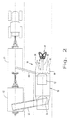
Fig. 2 is a top view of the harvester shown inFig. 1 , illustrating simultaneous unloading of both seed crop material and biomass crop material; -
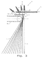
Fig. 3 is a side, partially sectional view of one embodiment of a seed harvester of the present invention; and -
Fig. 4 is a top view of the seed harvester shown inFig. 3 . - Referring now to
Figs. 1 and2 , there is shown an embodiment of an agricultural work machine in the form of aharvester 10 for a stalk-like crop 12 including bothbiomass crop material 14 andupper seed heads 16. Thebiomass crop material 14 may include both stalks and leaves, each of which may have value for certain applications, such as livestock feed, sugar production, ethanol production, etc. In the embodiment shown,crop 12 is a cane crop in the form of sweet sorghum but could be a different type of crop. - Harvester 10 generally includes a
base unit 18 carrying both abiomass harvester sub-system 20 andseed harvester sub-system 22. Each ofbiomass harvester sub-system 20 andseed harvester sub-system 22 are carried by the frame or chassis ofbase unit 18, withseed harvester sub-system 22 being positioned generally abovebiomass harvester sub-system 20. Biomassharvester sub-system 20 is used for harvesting thebiomass crop material 14, andseed harvester sub-system 22 is used for separately and independently harvesting and processing seed fromseed heads 16. Seedharvester sub-system 22 is also referred to as an upper cropmaterial gathering device 22 andbiomass harvester sub-system 20 is also referred to as a lower cropmaterial gathering device 20. - More particularly,
biomass harvester sub-system 20 has ageneral flow path 26 ofbiomass crop material 14 through harvester 10 (Fig. 1 ) which is below ageneral flow path 28 of seed from theseed heads 16 throughseed harvester sub-system 22. Theseparate flow paths biomass crop material 14 and seed crop material fromseed heads 16 to be separately processed and off-loaded fromharvester 10. - Biomass
harvester sub-system 20 includes abiomass harvester 24 carried bybase unit 18. Thebiomass harvester 24 includes abase cutter 30 which cuts the stalks ofcrop 12 near ground level. Thebiomass harvester sub-system 20 further includes a set offeed rollers 32, chopper unit 34, temporary storage bin 36 (also referred to as an "elevator basket"),elevator 38 andsecondary extractor 40. Each offeed rollers 32, chopper unit 34,elevator 38 andsecondary extractor 40 are of conventional construction on a sugar cane harvester and thus not described further herein. For example, chopper unit 34 chops the stalks of the biomass crop material into predetermined size billets. - However, according to an aspect of the present invention,
temporary storage bin 36 at the downstream side of chopper unit 34 provides temporary holding ofbiomass crop material 14 prior to being discharged fromsecondary extractor 40 into adump wagon 42 or other suitable portable container (Fig. 1 ). The ability to temporarily hold the biomass crop material onboardharvester 10 can be beneficial, e.g., when opening a field where thedump wagon 42 cannot drive along side ofharvester 10. -
Seed harvester sub-system 22 generally includes aseed harvester 44,grain storage tank 46, anddischarge conveyance 48.Discharge conveyance 48 is used to discharge the processed seed fromgrain storage tank 46 to adump wagon 50 or other suitable portable container (Fig. 1 ). In the illustrated embodiment,discharge conveyance 48 is configured as an auger, but could also be configured, e.g., as a belt conveyor or chain conveyor. -
Grain storage tank 46 is carriedonboard base unit 18, preferably at the front of the operator'sstation 52 onbase unit 18.Grain storage tank 46 may be constructed with a suitable shape (such as a rectangular shape with a V-bottom) from a suitable material (such as a metal or plastic). A cross-auger 54 positioned in the V-bottom moves the processed seed towarddischarge conveyance 48.Cross-auger 54 and dischargeconveyance 48 may be actuated using a single actuator, such as an electronic switch on a console panel within operator'sstation 52. -
Seed harvester 44 is positioned above and forward of base cutter 30 (relative to a working direction of harvester 10).Seed harvester 44 generally includes aseed removal unit 56 andseed conveyance 58.Seed conveyance 58 conveys the seed or seed heads fromseed harvester 44 tobase unit 18 for further processing withinseed harvester sub-system 22. InFig. 1 ,seed conveyance 58 may be configured as anauger 58 for transporting seeds tobase unit 12. Alsoseed conveyance 58 may be configured as achain conveyor 58 for transporting seed heads tobase unit 12, as illustrated inFig. 3 . However,seed conveyance 58 can be differently configured depending on the application, such as a cleated belt, etc. -
Seed removal unit 56 harvests the seed fromseed heads 16 by cutting off and subsequently processing theentire seed head 16. Referring toFigs. 3 and4 , aseed removal unit 56 is shown including aseed head cutter 62 for cuttingseed heads 16 from the stalks ofcrop 12. - During a field operation, and referring to
Figs. 3 and4 , seed heads 16 are cut fromcrop 12 usingseed head cutter 62. The seeds are held in agrain gathering tunnel 64, which can accommodate a changing height ofseed removal unit 56, and thus accommodate a changing angular orientation relative to seedconveyance 58. The seed heads are conveyed throughseed conveyance 58 so that the seeds may be removed from the seed heads using a suitable threshing assemblyonboard base unit 18. The threshed and cleaned seed are then deposited withingrain storage tank 46 where it is held until discharged frombase unit 18 usingdischarge conveyance 48. Concurrently, the biomass crop material (i.e., stalks and leaves) are aligned withsnout 66, cut off withbase unit 18, conveyed to chopper unit 34 usingfeed rollers 32, and deposited intemporary storage bin 36. The biomass crop material can then be selectively discharged fromtemporary storage bin 36 by an operator through engagement ofelevator 38 andsecondary extractor 40. - The stalks of
crop 12 include apeduncle 68, which is generally defined as the section of the stalk between the uppermost leaf ofcrop 12 andhead 16. The leaves ofcrop 12 being omitted for the sake of clarity.Seed removal unit 56 includes movingdevices 70 in the form ofgathering chains 70 to which are attached a plurality offingers 72.Fingers 72 are connected tochains 70 and are configured to meet in such a way as to form grippingareas 74 which substantially surround the stalk ofcrop 12 as the stalks are gathered towardseed cutter head 62. Seed cutter heads 62 include cuttingedges 76 and rotate about substantiallyvertical axes 78, being configured to cutpeduncle 68 of the stalks.Unsharpened portions 80 extend fromcutters 62 while sharpenededges 76 cut the stalk. The seeds, largely connected toseed heads 12, are collected bygrain gathering tunnel 64 and conveyed to a holding area by way ofseed conveyance 58. -
Grain gathering tunnel 64 includes atop plate 82, aback plate 84 and abottom plate 86.Hinges 88 allowplates seed conveyance 58 may be repositioned to accommodate different heights ofcrop 12 and specifically the locations ofheads 16.Seed conveyance 58, which may for example be in the form of a conveyor or auger, has an opening that corresponds to an opening inbottom plate 86 so that grain gathered ingrain gathering tunnel 64 can be conveyed therefrom. Althoughbottom plate 86 is shown as being along the top edge ofseed conveyance 58 it may be located along the side ofseed conveyance 58 and may be sloped to direct the grain to seedconveyance 58.Grain gathering tunnel 64 also has sides that are generally parallel with the direction of movement ofharvester 10 and may be in the form of a plate or a flexible element configured to adapt to the movement ofplates
Claims (10)
- A crop material gathering device (22) comprising:at least one moving device (70) configured to substantially surround a stalk of a cane crop plant as said at least one moving device (70) moves, the at least one moving device (70) being further configured to bend the head of the cane crop plant in a direction substantially opposite to a direction of travel; anda stalk cutting device (62) positioned proximate to said at least one moving device (70), said stalk engaging device (62) being configured to cut the peduncle of the cane crop plant.
- The gathering device (22) of claim 1, wherein said at least one moving device (70) includes a plurality of gathering plates (72) including a first gathering plate (72) and a second gathering plate (72), the stalk being substantially surrounded by said first gathering plate (72) and said second gathering plate (72) prior to the stalk encountering said stalk cutting device (62).
- The gathering device (22) of claim 2, wherein said stalk cutting device (62) includes at least one substantially circular blade having a plurality of protrusions extending therefrom, said protrusions (76) being configured to cut the stalk.
- The gathering (22) device of claim 3, wherein said blade rotates about a generally vertical axis.
- The gathering device (22) of claim 4, wherein said blade is located generally beneath said at least one moving device (70), said protrusions of said blade each having a sharpened edge (76) only along at least one of a leading and trailing edge.
- The gathering device (22) of claim 5, further comprising a grain gathering tunnel (64) positioned adjacent to said at least one moving device (70) and said blade to receive the head of the cane crop plant and grain.
- The gathering device (22) of claim 6, wherein said grain gathering tunnel (64) includes a top plate (82), a back plate (84) and a bottom plate (86), said top plate (82) being hingedly connected to said back plate (84), said back plate (84) being hingedly connected to said bottom plate (86).
- The crop material gathering device (22) of claim 6 or 7, further comprising a support member connectable to a chassis of a work machine (10), said support member being coupled to said at least one moving device (70), said roller (72) and said grain gathering tunnel (64), said support member including an internal grain moving device (58) for receiving grain from said grain gathering tunnel (64), said support member being configured to change a height that said crop material gathering device (22) is above the ground while maintaining said at least one moving device (70) substantially parallel to the ground.
- The crop material gathering device (22) of one of the preceding claims, couplable to a work machine (10) for harvesting a cane crop having a chassis to which is attached a lower crop material gathering (22) device.
- A work machine (10) for harvesting a cane crop, the work machine (10) comprising a chassis, a lower crop material gathering device (20) coupled to said chassis and an upper crop material gathering device (22) according to one of the preceding claims coupled to said chassis.
Applications Claiming Priority (1)
| Application Number | Priority Date | Filing Date | Title |
|---|---|---|---|
| US12/358,300 US7694501B1 (en) | 2009-01-23 | 2009-01-23 | Seed gathering device for use by an agricultural harvester |
Publications (2)
| Publication Number | Publication Date |
|---|---|
| EP2210469A1 true EP2210469A1 (en) | 2010-07-28 |
| EP2210469B1 EP2210469B1 (en) | 2013-04-10 |
Family
ID=42078082
Family Applications (1)
| Application Number | Title | Priority Date | Filing Date |
|---|---|---|---|
| EP09179393.5A Not-in-force EP2210469B1 (en) | 2009-01-23 | 2009-12-16 | A seed gathering device for use by an agricultural harvester |
Country Status (4)
| Country | Link |
|---|---|
| US (1) | US7694501B1 (en) |
| EP (1) | EP2210469B1 (en) |
| AU (1) | AU2010200099B2 (en) |
| BR (1) | BRPI1000129B1 (en) |
Families Citing this family (20)
| Publication number | Priority date | Publication date | Assignee | Title |
|---|---|---|---|---|
| US7805916B2 (en) * | 2009-01-23 | 2010-10-05 | Deere & Company | Seed gathering device for use by an agricultural harvester |
| US8220236B1 (en) * | 2009-07-09 | 2012-07-17 | Jeffrey D. Benner | Harvester for selectively cutting portions of crop materials |
| US8635843B2 (en) * | 2011-06-17 | 2014-01-28 | Altria Client Services Inc. | Apparatus and method of harvesting agricultural row crops having biased guide members |
| RU2496299C1 (en) * | 2012-03-22 | 2013-10-27 | Федеральное Государственное Бюджетное Образовательное Учреждение Высшего Профессионального Образования Дальневосточный Государственный Аграрный Университет | Method of harvesting corn for silage and device for its implementation |
| CN102783308B (en) * | 2012-07-27 | 2015-05-13 | 朱季华 | Header of cane harvester |
| US20140083073A1 (en) * | 2012-08-27 | 2014-03-27 | Arthur Charles Doerscher, SR. | Corn Stalk Harvester |
| ITTO20130328A1 (en) * | 2013-04-23 | 2014-10-24 | Agricoltura Cra | EQUIPMENT FOR THE DIFFERENTIATED COLLECTION OF VEGETABLE FRACTIONS OF A CULTURE AND AGRICULTURAL MACHINE USING A EQUIPMENT |
| BR102013028618B1 (en) * | 2013-11-06 | 2020-03-10 | Marchesan Implementos E Máquinas Agrícolas Tatú S/A | TUBULAR STRUCTURE APPLIED TO SUGAR CANE HARVEST |
| RU2606911C1 (en) * | 2015-09-28 | 2017-01-10 | Федеральное государственное бюджетное образовательное учреждение высшего образования "Астраханский государственный университет" | South cane harvesting device |
| CN105474874B (en) * | 2016-02-02 | 2018-01-09 | 张家口创鑫机械科技有限公司 | Crops harvest conveying device |
| US10143137B2 (en) * | 2016-05-16 | 2018-12-04 | Deere & Company | Harvester with multi-row topper |
| CN105900594B (en) * | 2016-06-13 | 2017-12-01 | 张自衡 | Self-propelled corn kernel direct is received, straw baling combined harvester |
| US10342176B2 (en) * | 2016-07-13 | 2019-07-09 | Monsanto Technology Llc | Angled sensor bar for detecting plants |
| RU2637810C1 (en) * | 2017-04-10 | 2017-12-07 | федеральное государственное бюджетное образовательное учреждение высшего образования "Волгоградский государственный аграрный университет" (ФГБОУ ВО Волгоградский ГАУ) | Machine for southern reed harvesting for pellets |
| BR102017015754B1 (en) | 2017-07-21 | 2022-09-27 | Indústrias Reunidas Colombo Ltda | SELF-ADJUSTING FEEDER FOR SUGARCANE HARVESTERS |
| AR116122A1 (en) * | 2018-10-02 | 2021-04-07 | Accorroni Rivas Bruno | SUGAR CANE BIOMASS MINCING MACHINE INCORPORATED ON A HARVESTER |
| US11277968B2 (en) * | 2019-03-27 | 2022-03-22 | Deere & Company | Secondary stalk roller |
| CN110547066B (en) * | 2019-08-20 | 2022-07-05 | 广西壮族自治区农业科学院 | Sugarcane seed stem cutting production line |
| CN110583140B (en) * | 2019-08-20 | 2022-07-05 | 广西壮族自治区农业科学院 | Healthy sugarcane seed stem production line |
| US11744183B2 (en) * | 2020-09-22 | 2023-09-05 | Jiangsu University | Sorghum cutting header and sorghum harvester with large feed volume and multiple reeling pans |
Citations (5)
| Publication number | Priority date | Publication date | Assignee | Title |
|---|---|---|---|---|
| US1334933A (en) * | 1919-10-01 | 1920-03-23 | Hamilton William Francis | Corn-header |
| US3144743A (en) * | 1960-03-31 | 1964-08-18 | Massey Ferguson Australia Ltd | Topping device for sugar cane harvester |
| US3791114A (en) | 1972-05-18 | 1974-02-12 | Sugar Cane Growers Coop | Two row cutter windrower harvesting machine |
| US4365461A (en) * | 1980-10-30 | 1982-12-28 | Instituto Venezolano De Investigaciones Cientificas (Ivic) | Implement for the harvesting of seed-producing plants by mechanical harvester |
| US20070209347A1 (en) * | 2004-09-14 | 2007-09-13 | Dan Malmros | Harvesting device |
Family Cites Families (13)
| Publication number | Priority date | Publication date | Assignee | Title |
|---|---|---|---|---|
| DE1917605A1 (en) * | 1968-04-09 | 1971-11-04 | Mini Ind Basica | Sugar cane harvester |
| BR7805293A (en) | 1978-08-17 | 1980-02-26 | Santal Equip Sa Com Ind | SUGAR CANE HARVESTER OR SIMILAR PRODUCTS |
| US4272947A (en) * | 1979-10-05 | 1981-06-16 | Mizzi Joseph M | Topping cutter for a cane harvester |
| DE4001460A1 (en) * | 1990-01-19 | 1991-07-25 | Claas Ohg | Implement to separate the tips of sugar cane - consists of feeding and cutting discs in front of revolving worm surrounded by trough shield |
| AU4173693A (en) * | 1992-10-29 | 1994-05-12 | Centro De Investigacion Y Asistencia Tecnica Del Estado De Queretaro, A.C. | Whole stalk sugar cane harvester that tops, cuts, cleans and loads |
| US5303533A (en) * | 1993-02-26 | 1994-04-19 | Lacane Manufacturing, Inc. | Cane harvester and method |
| US5485716A (en) * | 1993-09-07 | 1996-01-23 | Autoft Industries, Limited | Double row cane harvester |
| US5816036A (en) * | 1996-10-10 | 1998-10-06 | Jubal Watts | Apparatus and method for harvesting cane |
| US6076340A (en) * | 1998-01-20 | 2000-06-20 | Inter-American Vanguard Corporation | Sugar cane combine harvester |
| DE29817799U1 (en) | 1998-10-06 | 1998-12-17 | Claas Selbstfahrende Erntemaschinen GmbH, 33428 Harsewinkel | Sugar cane harvester |
| US6869356B2 (en) * | 2003-05-08 | 2005-03-22 | Deere & Company | Cleaning chamber and method for a sugarcane chopper harvester |
| US6910321B2 (en) * | 2003-08-08 | 2005-06-28 | Deere & Company | Air-assisted, topper/shredder for sugar cane harvester |
| US7040980B1 (en) | 2004-12-27 | 2006-05-09 | Kestel Frederick J | Combine harvester having double unloading auger system |
-
2009
- 2009-01-23 US US12/358,300 patent/US7694501B1/en active Active
- 2009-12-16 EP EP09179393.5A patent/EP2210469B1/en not_active Not-in-force
-
2010
- 2010-01-11 AU AU2010200099A patent/AU2010200099B2/en not_active Ceased
- 2010-01-21 BR BRPI1000129-8A patent/BRPI1000129B1/en active IP Right Grant
Patent Citations (5)
| Publication number | Priority date | Publication date | Assignee | Title |
|---|---|---|---|---|
| US1334933A (en) * | 1919-10-01 | 1920-03-23 | Hamilton William Francis | Corn-header |
| US3144743A (en) * | 1960-03-31 | 1964-08-18 | Massey Ferguson Australia Ltd | Topping device for sugar cane harvester |
| US3791114A (en) | 1972-05-18 | 1974-02-12 | Sugar Cane Growers Coop | Two row cutter windrower harvesting machine |
| US4365461A (en) * | 1980-10-30 | 1982-12-28 | Instituto Venezolano De Investigaciones Cientificas (Ivic) | Implement for the harvesting of seed-producing plants by mechanical harvester |
| US20070209347A1 (en) * | 2004-09-14 | 2007-09-13 | Dan Malmros | Harvesting device |
Also Published As
| Publication number | Publication date |
|---|---|
| AU2010200099B2 (en) | 2016-07-14 |
| BRPI1000129B1 (en) | 2022-04-12 |
| BRPI1000129A2 (en) | 2011-03-29 |
| EP2210469B1 (en) | 2013-04-10 |
| AU2010200099A1 (en) | 2010-08-12 |
| US7694501B1 (en) | 2010-04-13 |
Similar Documents
| Publication | Publication Date | Title |
|---|---|---|
| US7694501B1 (en) | Seed gathering device for use by an agricultural harvester | |
| US7805916B2 (en) | Seed gathering device for use by an agricultural harvester | |
| EP2210468B1 (en) | Agricultural harvester with simultaneous and independent seed and biomass processing | |
| US7524242B2 (en) | Collecting kernels of corn and cobs | |
| CN102523831B (en) | Bottom sickle for sugar-cane cutting machine | |
| US9386745B2 (en) | Corn header for a forage harvester including a side separating mechanism | |
| CN217470767U (en) | A dual system harvester for banded compound planting of maize soybean | |
| BE1024900B1 (en) | HALM DISTRIBUTOR WITH ADJUSTABLE POINT FOR A CUT BOARD | |
| US12274206B2 (en) | Universal crop head assembly and its use in harvesting crops | |
| US20040144074A1 (en) | Gathering and picking device | |
| US20110113743A1 (en) | Chopper assembly for a harvesting implement | |
| US9027316B2 (en) | Cutting header with finger mounted raised divider pans | |
| RU2192117C2 (en) | Method of harvesting cereal crops (versions) and apparatus | |
| EP3603378B1 (en) | Conveyor chain with multi-segment conveying floor | |
| US20190200528A1 (en) | Combine having conveyor chain slat assembly and method of harvesting crop thereof | |
| CN112106519B (en) | Castor plant picking table for castor plant harvesting machinery | |
| RU2748978C1 (en) | Method of harvesting soybeans with a cut of the stems below the root collar | |
| JPS6050409B2 (en) | combine | |
| US20250185538A1 (en) | Header monitoring system | |
| US6820404B1 (en) | Crop lifter | |
| CN210868801U (en) | Self-propelled corn harvester | |
| CN102090209A (en) | Long-stalked crop harvester | |
| RU32360U1 (en) | Seed Harvester | |
| CA2805967A1 (en) | Cutting header with finger mounted raised divider pans | |
| CN207653022U (en) | A kind of maize harvesting machine not to row nearside divider |
Legal Events
| Date | Code | Title | Description |
|---|---|---|---|
| PUAI | Public reference made under article 153(3) epc to a published international application that has entered the european phase |
Free format text: ORIGINAL CODE: 0009012 |
|
| AK | Designated contracting states |
Kind code of ref document: A1 Designated state(s): AT BE BG CH CY CZ DE DK EE ES FI FR GB GR HR HU IE IS IT LI LT LU LV MC MK MT NL NO PL PT RO SE SI SK SM TR |
|
| AX | Request for extension of the european patent |
Extension state: AL BA RS |
|
| 17P | Request for examination filed |
Effective date: 20110128 |
|
| 17Q | First examination report despatched |
Effective date: 20120730 |
|
| GRAP | Despatch of communication of intention to grant a patent |
Free format text: ORIGINAL CODE: EPIDOSNIGR1 |
|
| GRAS | Grant fee paid |
Free format text: ORIGINAL CODE: EPIDOSNIGR3 |
|
| GRAA | (expected) grant |
Free format text: ORIGINAL CODE: 0009210 |
|
| AK | Designated contracting states |
Kind code of ref document: B1 Designated state(s): AT BE BG CH CY CZ DE DK EE ES FI FR GB GR HR HU IE IS IT LI LT LU LV MC MK MT NL NO PL PT RO SE SI SK SM TR |
|
| REG | Reference to a national code |
Ref country code: GB Ref legal event code: FG4D |
|
| REG | Reference to a national code |
Ref country code: AT Ref legal event code: REF Ref document number: 605425 Country of ref document: AT Kind code of ref document: T Effective date: 20130415 Ref country code: CH Ref legal event code: EP |
|
| REG | Reference to a national code |
Ref country code: IE Ref legal event code: FG4D |
|
| REG | Reference to a national code |
Ref country code: DE Ref legal event code: R096 Ref document number: 602009014802 Country of ref document: DE Effective date: 20130606 |
|
| PG25 | Lapsed in a contracting state [announced via postgrant information from national office to epo] |
Ref country code: SI Free format text: LAPSE BECAUSE OF FAILURE TO SUBMIT A TRANSLATION OF THE DESCRIPTION OR TO PAY THE FEE WITHIN THE PRESCRIBED TIME-LIMIT Effective date: 20130410 |
|
| REG | Reference to a national code |
Ref country code: AT Ref legal event code: MK05 Ref document number: 605425 Country of ref document: AT Kind code of ref document: T Effective date: 20130410 |
|
| REG | Reference to a national code |
Ref country code: LT Ref legal event code: MG4D Ref country code: NL Ref legal event code: VDEP Effective date: 20130410 |
|
| PG25 | Lapsed in a contracting state [announced via postgrant information from national office to epo] |
Ref country code: SE Free format text: LAPSE BECAUSE OF FAILURE TO SUBMIT A TRANSLATION OF THE DESCRIPTION OR TO PAY THE FEE WITHIN THE PRESCRIBED TIME-LIMIT Effective date: 20130410 Ref country code: GR Free format text: LAPSE BECAUSE OF FAILURE TO SUBMIT A TRANSLATION OF THE DESCRIPTION OR TO PAY THE FEE WITHIN THE PRESCRIBED TIME-LIMIT Effective date: 20130711 Ref country code: NL Free format text: LAPSE BECAUSE OF FAILURE TO SUBMIT A TRANSLATION OF THE DESCRIPTION OR TO PAY THE FEE WITHIN THE PRESCRIBED TIME-LIMIT Effective date: 20130410 Ref country code: AT Free format text: LAPSE BECAUSE OF FAILURE TO SUBMIT A TRANSLATION OF THE DESCRIPTION OR TO PAY THE FEE WITHIN THE PRESCRIBED TIME-LIMIT Effective date: 20130410 Ref country code: FI Free format text: LAPSE BECAUSE OF FAILURE TO SUBMIT A TRANSLATION OF THE DESCRIPTION OR TO PAY THE FEE WITHIN THE PRESCRIBED TIME-LIMIT Effective date: 20130410 Ref country code: IS Free format text: LAPSE BECAUSE OF FAILURE TO SUBMIT A TRANSLATION OF THE DESCRIPTION OR TO PAY THE FEE WITHIN THE PRESCRIBED TIME-LIMIT Effective date: 20130810 Ref country code: LT Free format text: LAPSE BECAUSE OF FAILURE TO SUBMIT A TRANSLATION OF THE DESCRIPTION OR TO PAY THE FEE WITHIN THE PRESCRIBED TIME-LIMIT Effective date: 20130410 Ref country code: NO Free format text: LAPSE BECAUSE OF FAILURE TO SUBMIT A TRANSLATION OF THE DESCRIPTION OR TO PAY THE FEE WITHIN THE PRESCRIBED TIME-LIMIT Effective date: 20130710 Ref country code: ES Free format text: LAPSE BECAUSE OF FAILURE TO SUBMIT A TRANSLATION OF THE DESCRIPTION OR TO PAY THE FEE WITHIN THE PRESCRIBED TIME-LIMIT Effective date: 20130721 Ref country code: BE Free format text: LAPSE BECAUSE OF FAILURE TO SUBMIT A TRANSLATION OF THE DESCRIPTION OR TO PAY THE FEE WITHIN THE PRESCRIBED TIME-LIMIT Effective date: 20130410 Ref country code: PT Free format text: LAPSE BECAUSE OF FAILURE TO SUBMIT A TRANSLATION OF THE DESCRIPTION OR TO PAY THE FEE WITHIN THE PRESCRIBED TIME-LIMIT Effective date: 20130812 |
|
| PG25 | Lapsed in a contracting state [announced via postgrant information from national office to epo] |
Ref country code: LV Free format text: LAPSE BECAUSE OF FAILURE TO SUBMIT A TRANSLATION OF THE DESCRIPTION OR TO PAY THE FEE WITHIN THE PRESCRIBED TIME-LIMIT Effective date: 20130410 Ref country code: BG Free format text: LAPSE BECAUSE OF FAILURE TO SUBMIT A TRANSLATION OF THE DESCRIPTION OR TO PAY THE FEE WITHIN THE PRESCRIBED TIME-LIMIT Effective date: 20130710 Ref country code: PL Free format text: LAPSE BECAUSE OF FAILURE TO SUBMIT A TRANSLATION OF THE DESCRIPTION OR TO PAY THE FEE WITHIN THE PRESCRIBED TIME-LIMIT Effective date: 20130410 Ref country code: HR Free format text: LAPSE BECAUSE OF FAILURE TO SUBMIT A TRANSLATION OF THE DESCRIPTION OR TO PAY THE FEE WITHIN THE PRESCRIBED TIME-LIMIT Effective date: 20130410 Ref country code: CY Free format text: LAPSE BECAUSE OF FAILURE TO SUBMIT A TRANSLATION OF THE DESCRIPTION OR TO PAY THE FEE WITHIN THE PRESCRIBED TIME-LIMIT Effective date: 20130410 |
|
| PG25 | Lapsed in a contracting state [announced via postgrant information from national office to epo] |
Ref country code: CZ Free format text: LAPSE BECAUSE OF FAILURE TO SUBMIT A TRANSLATION OF THE DESCRIPTION OR TO PAY THE FEE WITHIN THE PRESCRIBED TIME-LIMIT Effective date: 20130410 Ref country code: SK Free format text: LAPSE BECAUSE OF FAILURE TO SUBMIT A TRANSLATION OF THE DESCRIPTION OR TO PAY THE FEE WITHIN THE PRESCRIBED TIME-LIMIT Effective date: 20130410 Ref country code: DK Free format text: LAPSE BECAUSE OF FAILURE TO SUBMIT A TRANSLATION OF THE DESCRIPTION OR TO PAY THE FEE WITHIN THE PRESCRIBED TIME-LIMIT Effective date: 20130410 Ref country code: EE Free format text: LAPSE BECAUSE OF FAILURE TO SUBMIT A TRANSLATION OF THE DESCRIPTION OR TO PAY THE FEE WITHIN THE PRESCRIBED TIME-LIMIT Effective date: 20130410 |
|
| PGFP | Annual fee paid to national office [announced via postgrant information from national office to epo] |
Ref country code: DE Payment date: 20131120 Year of fee payment: 5 Ref country code: GB Payment date: 20131227 Year of fee payment: 5 |
|
| PLBE | No opposition filed within time limit |
Free format text: ORIGINAL CODE: 0009261 |
|
| STAA | Information on the status of an ep patent application or granted ep patent |
Free format text: STATUS: NO OPPOSITION FILED WITHIN TIME LIMIT |
|
| PG25 | Lapsed in a contracting state [announced via postgrant information from national office to epo] |
Ref country code: RO Free format text: LAPSE BECAUSE OF FAILURE TO SUBMIT A TRANSLATION OF THE DESCRIPTION OR TO PAY THE FEE WITHIN THE PRESCRIBED TIME-LIMIT Effective date: 20130410 Ref country code: IT Free format text: LAPSE BECAUSE OF FAILURE TO SUBMIT A TRANSLATION OF THE DESCRIPTION OR TO PAY THE FEE WITHIN THE PRESCRIBED TIME-LIMIT Effective date: 20130410 |
|
| PGFP | Annual fee paid to national office [announced via postgrant information from national office to epo] |
Ref country code: FR Payment date: 20131217 Year of fee payment: 5 |
|
| 26N | No opposition filed |
Effective date: 20140113 |
|
| REG | Reference to a national code |
Ref country code: DE Ref legal event code: R097 Ref document number: 602009014802 Country of ref document: DE Effective date: 20140113 |
|
| REG | Reference to a national code |
Ref country code: CH Ref legal event code: PL |
|
| PG25 | Lapsed in a contracting state [announced via postgrant information from national office to epo] |
Ref country code: MC Free format text: LAPSE BECAUSE OF FAILURE TO SUBMIT A TRANSLATION OF THE DESCRIPTION OR TO PAY THE FEE WITHIN THE PRESCRIBED TIME-LIMIT Effective date: 20130410 Ref country code: LU Free format text: LAPSE BECAUSE OF FAILURE TO SUBMIT A TRANSLATION OF THE DESCRIPTION OR TO PAY THE FEE WITHIN THE PRESCRIBED TIME-LIMIT Effective date: 20131216 |
|
| REG | Reference to a national code |
Ref country code: IE Ref legal event code: MM4A |
|
| PG25 | Lapsed in a contracting state [announced via postgrant information from national office to epo] |
Ref country code: IE Free format text: LAPSE BECAUSE OF NON-PAYMENT OF DUE FEES Effective date: 20131216 Ref country code: CH Free format text: LAPSE BECAUSE OF NON-PAYMENT OF DUE FEES Effective date: 20131231 Ref country code: LI Free format text: LAPSE BECAUSE OF NON-PAYMENT OF DUE FEES Effective date: 20131231 |
|
| PG25 | Lapsed in a contracting state [announced via postgrant information from national office to epo] |
Ref country code: SM Free format text: LAPSE BECAUSE OF FAILURE TO SUBMIT A TRANSLATION OF THE DESCRIPTION OR TO PAY THE FEE WITHIN THE PRESCRIBED TIME-LIMIT Effective date: 20130410 |
|
| PG25 | Lapsed in a contracting state [announced via postgrant information from national office to epo] |
Ref country code: TR Free format text: LAPSE BECAUSE OF FAILURE TO SUBMIT A TRANSLATION OF THE DESCRIPTION OR TO PAY THE FEE WITHIN THE PRESCRIBED TIME-LIMIT Effective date: 20130410 |
|
| REG | Reference to a national code |
Ref country code: DE Ref legal event code: R119 Ref document number: 602009014802 Country of ref document: DE |
|
| PG25 | Lapsed in a contracting state [announced via postgrant information from national office to epo] |
Ref country code: HU Free format text: LAPSE BECAUSE OF FAILURE TO SUBMIT A TRANSLATION OF THE DESCRIPTION OR TO PAY THE FEE WITHIN THE PRESCRIBED TIME-LIMIT; INVALID AB INITIO Effective date: 20091216 Ref country code: MK Free format text: LAPSE BECAUSE OF FAILURE TO SUBMIT A TRANSLATION OF THE DESCRIPTION OR TO PAY THE FEE WITHIN THE PRESCRIBED TIME-LIMIT Effective date: 20130410 |
|
| GBPC | Gb: european patent ceased through non-payment of renewal fee |
Effective date: 20141216 |
|
| PG25 | Lapsed in a contracting state [announced via postgrant information from national office to epo] |
Ref country code: MT Free format text: LAPSE BECAUSE OF FAILURE TO SUBMIT A TRANSLATION OF THE DESCRIPTION OR TO PAY THE FEE WITHIN THE PRESCRIBED TIME-LIMIT Effective date: 20130410 |
|
| REG | Reference to a national code |
Ref country code: FR Ref legal event code: ST Effective date: 20150831 |
|
| PG25 | Lapsed in a contracting state [announced via postgrant information from national office to epo] |
Ref country code: GB Free format text: LAPSE BECAUSE OF NON-PAYMENT OF DUE FEES Effective date: 20141216 Ref country code: DE Free format text: LAPSE BECAUSE OF NON-PAYMENT OF DUE FEES Effective date: 20150701 |
|
| PG25 | Lapsed in a contracting state [announced via postgrant information from national office to epo] |
Ref country code: FR Free format text: LAPSE BECAUSE OF NON-PAYMENT OF DUE FEES Effective date: 20141231 |