EP2209724B1 - Behälterverpackung - Google Patents
Behälterverpackung Download PDFInfo
- Publication number
- EP2209724B1 EP2209724B1 EP08850526A EP08850526A EP2209724B1 EP 2209724 B1 EP2209724 B1 EP 2209724B1 EP 08850526 A EP08850526 A EP 08850526A EP 08850526 A EP08850526 A EP 08850526A EP 2209724 B1 EP2209724 B1 EP 2209724B1
- Authority
- EP
- European Patent Office
- Prior art keywords
- panel
- gusset
- package
- foldably connected
- blank
- Prior art date
- Legal status (The legal status is an assumption and is not a legal conclusion. Google has not performed a legal analysis and makes no representation as to the accuracy of the status listed.)
- Active
Links
- 238000000034 method Methods 0.000 claims description 13
- 239000000853 adhesive Substances 0.000 claims description 9
- 230000001070 adhesive effect Effects 0.000 claims description 9
- 235000013361 beverage Nutrition 0.000 claims description 6
- 230000014759 maintenance of location Effects 0.000 abstract description 2
- 239000000463 material Substances 0.000 description 15
- 210000003739 neck Anatomy 0.000 description 7
- 239000003292 glue Substances 0.000 description 5
- 239000011087 paperboard Substances 0.000 description 4
- 238000012986 modification Methods 0.000 description 3
- 230000004048 modification Effects 0.000 description 3
- 239000004927 clay Substances 0.000 description 2
- 239000011248 coating agent Substances 0.000 description 2
- 238000000576 coating method Methods 0.000 description 2
- 239000013256 coordination polymer Substances 0.000 description 2
- 238000004806 packaging method and process Methods 0.000 description 2
- 239000000123 paper Substances 0.000 description 2
- 239000004033 plastic Substances 0.000 description 2
- 229920003023 plastic Polymers 0.000 description 2
- VGGSQFUCUMXWEO-UHFFFAOYSA-N Ethene Chemical compound C=C VGGSQFUCUMXWEO-UHFFFAOYSA-N 0.000 description 1
- 229920000219 Ethylene vinyl alcohol Polymers 0.000 description 1
- 239000004677 Nylon Substances 0.000 description 1
- 239000004743 Polypropylene Substances 0.000 description 1
- 239000004793 Polystyrene Substances 0.000 description 1
- 230000004308 accommodation Effects 0.000 description 1
- 238000007792 addition Methods 0.000 description 1
- 229910052782 aluminium Inorganic materials 0.000 description 1
- XAGFODPZIPBFFR-UHFFFAOYSA-N aluminium Chemical compound [Al] XAGFODPZIPBFFR-UHFFFAOYSA-N 0.000 description 1
- 230000004888 barrier function Effects 0.000 description 1
- 239000011111 cardboard Substances 0.000 description 1
- UFRKOOWSQGXVKV-UHFFFAOYSA-N ethene;ethenol Chemical compound C=C.OC=C UFRKOOWSQGXVKV-UHFFFAOYSA-N 0.000 description 1
- 239000004715 ethylene vinyl alcohol Substances 0.000 description 1
- 210000003811 finger Anatomy 0.000 description 1
- 239000011521 glass Substances 0.000 description 1
- 229920001903 high density polyethylene Polymers 0.000 description 1
- 239000004700 high-density polyethylene Substances 0.000 description 1
- 229920000092 linear low density polyethylene Polymers 0.000 description 1
- 239000004707 linear low-density polyethylene Substances 0.000 description 1
- 229920001684 low density polyethylene Polymers 0.000 description 1
- 239000004702 low-density polyethylene Substances 0.000 description 1
- 229910052751 metal Inorganic materials 0.000 description 1
- 239000002184 metal Substances 0.000 description 1
- 150000002739 metals Chemical class 0.000 description 1
- 239000000203 mixture Substances 0.000 description 1
- 229920001778 nylon Polymers 0.000 description 1
- 229920000139 polyethylene terephthalate Polymers 0.000 description 1
- 239000005020 polyethylene terephthalate Substances 0.000 description 1
- 229920000915 polyvinyl chloride Polymers 0.000 description 1
- 239000004800 polyvinyl chloride Substances 0.000 description 1
- 230000000717 retained effect Effects 0.000 description 1
- 210000003813 thumb Anatomy 0.000 description 1
- 230000007704 transition Effects 0.000 description 1
- 239000002966 varnish Substances 0.000 description 1
- 230000003313 weakening effect Effects 0.000 description 1
Images


Classifications
-
- B—PERFORMING OPERATIONS; TRANSPORTING
- B65—CONVEYING; PACKING; STORING; HANDLING THIN OR FILAMENTARY MATERIAL
- B65D—CONTAINERS FOR STORAGE OR TRANSPORT OF ARTICLES OR MATERIALS, e.g. BAGS, BARRELS, BOTTLES, BOXES, CANS, CARTONS, CRATES, DRUMS, JARS, TANKS, HOPPERS, FORWARDING CONTAINERS; ACCESSORIES, CLOSURES, OR FITTINGS THEREFOR; PACKAGING ELEMENTS; PACKAGES
- B65D71/00—Bundles of articles held together by packaging elements for convenience of storage or transport, e.g. portable segregating carrier for plural receptacles such as beer cans or pop bottles; Bales of material
- B65D71/40—Bundles of articles held together by packaging elements for convenience of storage or transport, e.g. portable segregating carrier for plural receptacles such as beer cans or pop bottles; Bales of material comprising a plurality of articles held together only partially by packaging elements formed by folding a blank or several blanks
- B65D71/42—Bundles of articles held together by packaging elements for convenience of storage or transport, e.g. portable segregating carrier for plural receptacles such as beer cans or pop bottles; Bales of material comprising a plurality of articles held together only partially by packaging elements formed by folding a blank or several blanks formed by folding a single blank into a single layer element
Definitions
- the present invention relates to a package according to the preamble of claim 1 and to a blank for forming a package according to the preamble of claim 10, respectively. Moreover, the present invention relates to a method of forming a package. More generally, the present invention relates to packages or cartons for holding and carrying containers.
- a package for containing a plurality of articles as defined in the preamble of claim 1 and a blank for forming a package as defined in the preamble of claim 10 are known from EP 240126 A2 .
- This reference teaches a package incorporating a group of flanged containers in two rows and a panel structure.
- the panel structure comprises a top panel which overlies the tops of the containers, end panels foldably connected to the top panel at opposed ends thereof, and side panels which are connected to the top panel through securing strips.
- the securing strips engage, at the undersides thereof, the flanges of the containers.
- At the corners there are provided web structures by which the end panels and the side panels are connected. Said web structures may either comprise two web panels foldably connected to one another ( Figs. 1-3 ) or one web panel with a fixing tab which cooperates with a fixing slot into which is to be inserted ( Fig. 4-6 ).
- the present invention aims at providing for an improved package of the generic type and an improved blank of the generic type, respectively.
- the object set out above is achieved by a package as defined in claim 1 and by a blank as defined in claim 10, respectively. Moreover, the method of forming a package as defined in claim 15 provides for a solution of the above object.
- one aspect of the disclosure is generally directed to a package for holding a plurality of containers.
- the package has a top panel and a side panel.
- the package has retention features for retaining the containers and gusset features for facilitating forming of the package.
- the disclosure is generally directed to a package for containing a plurality of articles.
- the package comprises panels that extend at least partially around an interior of the package.
- the panels comprise a top panel, a side panel foldably connected to the top panel, and an end panel foldably connected to the top panel. At least one opening in the top panel is for at least partially receiving at least a portion of one of the articles.
- a first gusset panel is foldably connected to the side panel, and a second gusset panel is foldably connected to the first gusset panel and the end panel.
- the disclosure is generally directed to a blank for forming a package for containing a plurality of articles.
- the blank comprises panels that comprise a top panel, a side panel foldably connected to the top panel, and an end panel foldably connected to the top panel. At least one receptacle is in the top panel.
- a first gusset panel is foldably connected to the side panel, and a second gusset panel is foldably connected to the first gusset panel and the end panel.
- the disclosure is generally directed to a method of forming a package.
- the method comprises providing a blank comprising a top panel, a side panel foldably connected to the top panel, an end panel foldably connected to the top panel, a plurality of receptacles in the top panel, a first gusset panel foldably connected to the side panel, and a second gusset panel foldably connected to the first gusset panel and the end panel.
- the method further comprising positioning a plurality of articles relative to the blank and positioning the blank relative to the articles so that the plurality of articles are at least partially received in respective receptacles of the plurality of receptacles.
- the method further comprises downwardly folding the end panel relative to the top panel to at least partially enclose the articles in an interior space of the package and downwardly folding the side panel relative to the top panel to at least partially enclose the articles in the interior space of the package.
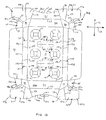
- Fig. 1 is a plan view of an exterior side of a blank used to form a package according to a first embodiment of the disclosure.
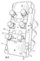
- Fig. 2 is a top view of the blank of Fig. 1 partially erected into the package.
- Fig. 3 is a view of the blank of Fig. 1 further partially erected.
- Fig. 4 is a view of the blank of Fig. 1 further partially erected.
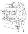
- Figs. 5 and 6 are views of the blank of Fig. 1 showing alternative steps for erecting the package of the first embodiment.
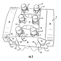
- Fig. 7 is a side perspective of the package formed from the blank of Fig. 1 .
- Fig. 8 is a plan view of an exterior side of a blank used to form a package according to a second embodiment.
- Fig. 9 is a plan view of an exterior side of a blank used to form a package according to a third embodiment.
- Fig. 10 is a view of the blank of Fig. 9 partially erected into the package of the third embodiment.
- Fig. 11 is a side perspective of the package according to the third embodiment.
- Fig. 12 is a view of the blank of Fig. 9 showing alternative steps for erecting the package of the third embodiment.
- Fig. 13 is a plan view of an exterior side of a blank used to form a package according to a fourth embodiment.
- the present disclosure generally relates to constructs, sleeves, cartons, or the like, and packages for holding and displaying containers such as jars, bottles, cans, etc.
- the containers can be used for packaging food and beverage products, for example.
- the containers can be made from materials suitable in composition for packaging the particular food or beverage item, and the materials include, but are not limited to, plastics such as PET, LDPE, LLDPE, HDPE, PP, PS, PVC, EVOH, and Nylon; and the like; aluminum and/or other metals; glass; or any combination thereof.
- Packages according to the present disclosure can accommodate containers of numerous different shapes.
- beverage containers e.g., plastic containers
- the terms “lower,” “bottom,” “upper” and “top” indicate orientations determined in relation to fully erected packages.
- a package or carrier 150 is illustrated in its erected state in Fig. 7 , in which it is attached to containers C arranged in two rows of three containers.
- the containers C are illustrated as beverage containers having a top portion generally comprising a flange portion F and an upper neck portion N, and a cap CP, but containers of other sizes, shapes, and configurations may be held in the package 150 without departing from the disclosure.
- the upper neck portion N of the containers are receive in respective openings 18 (e.g., receptacle) ( Fig. 2 ) in the package and retained in the package by retaining features described further herein.
- the containers could be arranged in other than a 2x3 arrangement (e.g., 2x4, 1x3, 1x4, etc.) without departing from the disclosure.
- Fig. 1 is a plan view of an exterior side 3 of a blank 8 used to form the package or carrier 150.
- the blank 8 has a longitudinal axis L1 and a lateral axis L2.
- the blank 8 comprises a top panel 10 foldably connected to a first end panel 20 at a first lateral fold line 21 and foldably connected to a second end panel 30 at a second lateral fold line 31.
- a first side panel 40 is foldably connected to the top panel 10 at a first longitudinal fold line 41.
- a second side panel 50 is foldably connected to the top panel 10 at a second longitudinal fold line 51.
- the blank 8 includes six receptacles 12 formed by tabs 22 and 24, which are connected to the top panel 10 by respective fold lines 37, 39.
- Slits 62 and 63 separate the tabs 22, 24 and arcuate slits 64 separate the tab fold lines 37, 39.
- the arcuate slits 64 and tab fold lines 37, 39 extend around and define a periphery of each of the openings 18 in the top panel 10.
- the tabs 22, 24 surrounding each opening 18 Fig.
- tabs 22, 24 are of different sizes so that when containers C are inserted into the openings 18 and the tabs 22, 24 are upwardly struck from the top panel 10, the shorter tabs 22 contact only the necks N of the containers and the longer tabs 24 contact both the necks and the underside of the flanges F to support the containers when the carrier is lifted.
- tabs e.g., tabs 22, 24
- the diameter of the openings 18 ( Fig. 2 ) in the top panel 10 is related to the diameter of the neck portion N of the containers C to be packaged so that the containers are able to pass through the opening while contacting the support tabs 22, 24 of the receptacles 12 to pivot the support tabs up about their fold lines.
- the support tabs 22, 24 at the corner openings 18 are of somewhat different design than the support tabs 22 and 24 at the central openings.
- the support tabs 22, 24 take the form of four contiguous tabs arranged so that the fold lines 37, 39 of adjacent tabs are at right angles to each other. In both cases, one pair of oppositely located tabs 24 is longer than the other pair 22.
- the tabs 22, 24, slits 62, 63, 64, and fold lines 37, 39 of the receptacle 12 at each of the two corners of the top panel 10 adjacent the second end panel 30 are respectively rotated clockwise and counterclockwise approximately 45 degrees from the orientation of the tabs, slits, and fold lines of the two central receptacles.
- the tabs 22, 24 , slits 62, 63, 64, and fold lines 37, 39 of the receptacle 12 at each corner of the top panel 10 adjacent the first end panel 20 are respectively rotated counterclockwise and clockwise approximately 45 degrees from the orientation of the tabs, slits, and fold lines of the four central openings.
- the receptacles 12 in the top panel 10 can have other features including other tabs, slits, fold lines, tear lines, etc., and may be otherwise arranged and/or configured, without departing from the disclosure.
- the blank 8 includes corner cutouts 32 generally adjacent a respective corner of the top panel 10.
- Fold line 42 in the side panel 40 and fold line 52 in side panel 50 extend between respective cutouts 32 in each side panel to form sloped side panel sections which generally conform to the slope of the bottles in the transition area between the bottle neck and the barrel of the bottle.
- the corner cutouts 32 could be otherwise shaped, arranged, and/or configured, or could be omitted without departing from the disclosure.
- the blank 8 is preferably formed of paperboard, but may be of any suitable material having sufficient strength and flexibility to function in the manner of paperboard.
- the side panels 40, 50 are longer than the length of the top panel 10, terminating beyond the cutouts 32.
- First and second gusset panels 45, 47 are located at each corner of the blank 8 between respective side panels 40, 50 and end panels 20, 30.
- the end panels 20, 30 comprise a corner portion 49 foldably connected to the second gusset panels 47 and connected to the end panels.
- the gusset panels 45, 47 and corner portions 49 of the end panels 20, 30 are foldably connected by respective fold lines 53, 55, 57, 59.
- the gusset panels 45, 47 and corner panels 49 facilitate forming of the package 150 in a manner so that the package conforms to the shape of the containers C.
- the first gusset panel 45 is foldably connected to one of the side panels 40, 50 at the fold line 53
- the second gusset panel 47 is foldably connected to the first gusset panel at a fold line 55.
- the second gusset panel is foldably connected to the corner portion 49 of the end panels 20, 30 at the fold line 57.
- the corner portion 49 is foldably connected to a respective end panel 20, 30 at the fold line 59.
- the first and second gusset panels 45, 47 and corner portion 49 could be otherwise shaped, arranged, and/or configured without departing from the disclosure.
- the corner portions 49 of each end panel 20, 30 could be omitted without departing from the disclosure.
- the blank 8 includes two handle panels 84 foldably connected to the top panel 10 by lateral fold lines 86.
- the handle panels 84 are further defined by curved cuts 87, 89, 91 in the top panel.
- the blank 8 could include handle features other than the handle panels 84 or the handle panels could be otherwise shaped, arranged, and/or configured without departing from the disclosure.
- bottles C to be packaged are grouped together and the top panel 10 is first pushed down over the tops of the bottles C.
- the caps CP of the bottles C contact the support tabs 22, 24 to pivot the support tabs up relative to the top panel 10 to create the openings 18 in the top panel.
- Relative upward movement of the containers C continues until the support tabs 24 snap into place as the edges of these tabs engage the underside of the bottle flanges F ( Fig. 3 ).
- the shorter tabs 22 do not reach the flanges F but snugly engage the bottle necks.
- the end panels 20, 30 are downwardly folded relative to the top panel 10 in the direction of arrow A1.
- the second gusset panels 47 are folded inwardly in the direction of arrow A2 ( Fig. 4 ) so as to cause an adjacent first gusset 45 and side panel 40, 50 to fold downwardly to the position of Fig. 4 .
- the second gusset panel 47 and first gusset panel 45 are brought into face-to-face relationship such that the second gusset panel 47 is in contact with and overlapped by the first gusset panel 45.
- a portion of a respective side panel 40, 50 is in face-to-face relationship with the first gusset panel 45 so that the portion of the respective side panel overlays and is in contact with the first gusset panel.
- the corner portion 49 of the end panels 20, 30 helps facilitate inward folding of the second gusset panel 47 and conforms the package 150 to a tight fit against the corner containers C.
- Adhesive such as glue may be applied to the second gusset panel 47 or the first gusset panel 45 to secure the side panels 40, 50 in the downwardly folded position.
- adhesive e.g., glue
- glue can be applied to the first gusset panel 45 or a portion of a respective side panel 40, 50 that overlays the first gusset panel to secure the side panels in the downwardly folded position.
- the package 150 can be formed by other folding and panel positioning steps.
- Figs. 5 and 6 show an alternative configuration for forming the blank 8 into the package 150.
- the side panels 40, 50 can be folded downward at fold lines 41, 51 relative to the top panel 10 in the direction of arrow A3 prior to the downward folding of the end panels 20, 30.
- the first gusset panel 45 can be folded inwardly in the direction of arrow A4 to assist in downwardly folding the second gusset panel 47 and the end panels 20, 30.
- Glue or other adhesive can be applied to either or both of the gusset panels 45, 47 prior to downwardly folding the end panels 20, 30.
- the gusset panels 45, 47 are in face-to-face contact with the second gusset panel 47 overlaying the first gusset panel 45.
- the corner portions 49 of the end panels 20, 30 is in face-to-face relationship with the second gusset panel 47.
- Adhesive can be applied to one or more than one of the end panels 20,30, the first gusset panels 45, the second gusset panels 47, or the side panels 40, 50 to secure the package 150 in the formed position.
- the package 150 can be maintained in the assembled configuration by the adhesive between the overlapped and adhered gusset panels 45, 47 or other panels.
- Other folding, assembly, or forming steps and configurations are within the scope of this disclosure.
- Fig. 8 shows a blank 208 of a second embodiment of the disclosure having similar features as the first embodiment. Accordingly, similar or identical features of the embodiments are provided with like or similar reference numbers.
- the blank 208 of the second embodiment includes a smaller opening 32 at each corner and the gusset panels 45, 47 have a different shape than the gusset panels of the first embodiment.
- the side panels 40, 50 include additional longitudinal fold lines 42a, 52a extending between respective openings 32. Each side panel 40, 50 has an additional foldable panel for positioning relative to the top panel 10.
- the blank 208 can be formed into a package in a similar manner described above for forming the blank 8 into the package 150.
- Fig. 9 shows a blank 308 for forming a package 350 of a third embodiment of the disclosure.
- the blank 308 has similar features as the previous embodiments. Accordingly, similar or identical features of the embodiments are provided with like or similar reference numbers.
- the blank 308 of the third embodiment has first and second gusset panels 45, 47 that function in a similar manner as the first and second gusset panels of the previous embodiments.
- each of the second gusset panels 47 has a base portion 47a adjacent the opening 32 and an extension 47b that includes a distal portion of the gusset panel extending from the base portion.
- the extension 47b of each of the second gusset panels 47 extends laterally outward beyond an edge 45a of the first gusset panel 45.
- the base portion 47a of the second gusset panel 47 is foldably connected to the corner portion 49 of the end panel 20, 30 at the fold line 57 and is foldably connected to the gusset panel 45 at the fold line 53.
- the extensions 47b allow a larger target area for the application of adhesive to the package 350.
- each of the first gusset panels 45 of the third embodiment are smaller that the previous embodiments so that the extension 47b can extend outward from the edge 45a of the first gusset panel and underlie at least a portion of the side panels 40, 50 when the package 350 is assembled.
- the package 350 can be assembled in a similar manner as the first embodiment by first downwardly folding the end flaps 20, 30 in the direction of arrow A5 ( Fig. 10 ).
- the second gusset panels 47 are inwardly folded in the direction of arrow A6 to lower the first gusset panels 45 and the side panels 40, 50.
- the side panels 40, 50 are further lowered in the direction of arrow A7, the first gusset panels 45 are brought into face-to-face contact with the base portion 47a of the gusset panel 47.
- the extensions 47b extend beyond the edge 45a of the first gusset panels 45.
- the side panels 40, 50 are further downwardly folded, the side panels overlap and are in a generally face-to-face relationship with the first gusset panels 45 that overlap the base portions 47a of the gusset panels 47 and the extensions 47b of the gusset panels 47.
- Adhesive can be applied to the extensions 47b (or the side panels 40, 50) so that at least a portion of the side panels 40, 50 is adhered to at least a portion of the extensions 47b of the second gusset panels 47.
- the base portions 47a of the second gusset panels 47 can be adhered to the first gusset panels 45.
- Other folding and assembly steps and configurations are within the scope of this disclosure.
- Fig. 13 shows a blank 408 of a fourth embodiment of the disclosure having similar features as the blank 308 of the third embodiment. Accordingly, similar or identical features of the embodiments are provided with like or similar reference numbers.
- the blank 408 of the fourth embodiment includes first gusset panels 45 that each have an oblique fold line 55a that is parallel to and spaced-apart from the fold line 55 connecting each of the first gusset panels to a respective second gusset panel 47.
- the additional fold line 55a of the fourth embodiment allows the gusset panels 45, 47 and to more closely conform to a variety of containers C having different sizes.
- the fold line 53 connecting each of the first gusset panels 45 to a respective side panel 40, 50 slopes upward or downward (depending on the frame of reference) relative to the lateral axis L2 as the fold line extends from the edge 45a of the first gusset panel to the opening 32.
- the first gusset panels 45 and the second gusset panels 47 are larger than the corresponding gusset panels of the previous embodiments to provide larger surface areas for securing the gusset panels in the assembled configuration.
- the gusset panels 45, 47 could be otherwise shaped and could include other features without departing from the disclosure.
- each end panel 20, 30 includes a respective lateral fold line 23, 33 so that each end panel is divided into two portions 20a, 20b, and 30a, 30b that are independently foldably connected at a respective lateral fold line.
- Each outer portion 20a, 30a of end panels 20, 30 has a respective curved edge 30c, 20c.
- Each end panel 20, 30 comprises a respective handle panel 121, 123 foldably connected to a respective end panel at a curved fold line 125, 127.
- the blank 408 includes handle features 184 in the top panel.
- the handle features comprising respective handle panels 185, 187 that are foldably connected to the top panel 10 at respective fold lines 189, 190.
- the package can be grasped at the end panels 20, 30 by folding under the handle panel 121, 123 and can be grasped at the top panel by folding in the handle panels 185, 187.
- a user can place their thumb against either group of handle panels 185, 184 and can place their other four fingers of the same hand on one of the handle panels 121, 123 to fold the handle panel in for grasping the package at the end panel 20, 30.
- the package formed from the blank 408 can be grasped and carried by a user.
- only the handle features 184 can be used to grasp the package formed from the blank 408 or only the handle panels 121, 123 in the end panels 20, 30 can be used to grasp the package formed from the blank.
- the blank 408 and package formed from the blank can have other handle features or the handle features shown can be omitted without departing from the disclosure.
- the blank 408 has dispensing features for removal of the containers C from the package formed from the blank.
- Each side panel 40, 50 has two tabs 191, 193 formed by a respective tear line 195, 197 in the side panel between a respective longitudinal fold line 41, 51 connecting the side panel to the top panel 10 and a longitudinal fold line 42, 52 forming the sloped side panel sections.
- the top panel 10 includes oblique cuts 199 adjacent a respective tabs 191, 193 that facilitate tearing of the top panel when the tabs 191, 193 are activated by separating the tabs from the side panels 40, 50.
- a respective tab 191, 193 can be grasped and lifted upward to separate the tab from the side panel 40, 50.
- the respective tab 191, 193 can be further positioned and pulled to initiate tearing or deformation of the top panel 10 at the cuts 199 to facilitate removal of the containers C from a respective receptacle 12.
- the blank 408 and package formed from the blank can have other dispensing features or the dispensing features illustrated and described herein can be changed or omitted without departing from the disclosure.
- the blank 408 can be formed into a package in a similar manner described above for the previous embodiments.
- the blanks according to the present disclosure can be, for example, formed from coated paperboard and similar materials.
- the interior and/or exterior sides of the blanks can be coated with a clay coating.
- the clay coating may then be printed over with product, advertising, price coding, and other information or images.
- the blanks may then be coated with a varnish to protect any information printed on the blank.
- the blanks may also be coated with, for example, a moisture barrier layer, on either or both sides of the blank.
- the blanks may be constructed of paperboard of a caliper such that it is heavier and more rigid than ordinary paper.
- the blanks can also be constructed of other materials, such as cardboard, hard paper, or any other material having properties suitable for enabling the carton to function at least generally as described herein.
- the blanks can also be laminated or coated with one or more sheet-like materials at selected panels or panel sections.
- a fold line can be any substantially linear, although not necessarily straight, form of weakening that facilitates folding therealong. More specifically, but not for the purpose of narrowing the scope of the present disclosure, fold lines include: a score line, such as lines formed with a blunt scoring knife, or the like, which creates a crushed portion in the material along the desired line of weakness; a cut that extends partially into a material along the desired line of weakness, and/or a series of cuts that extend partially into and/or completely through the material along the desired line of weakness; and various combinations of these features.
- a score line such as lines formed with a blunt scoring knife, or the like, which creates a crushed portion in the material along the desired line of weakness
- a cut that extends partially into a material along the desired line of weakness, and/or a series of cuts that extend partially into and/or completely through the material along the desired line of weakness; and various combinations of these features.
- a tear line can include: a slit that extends partially into the material along the desired line of weakness, and/or a series of spaced apart slits that extend partially into and/or completely through the material along the desired line of weakness, or various combinations of these features.
- one type tear line is in the form of a series of spaced apart slits that extend completely through the material, with adjacent slits being spaced apart slightly so that a nick (e.g., a small somewhat bridging-like piece of the material) is defined between the adjacent slits for typically temporarily connecting the material across the tear line. The nicks are broken during tearing along the tear line.
- the nicks typically are a relatively small percentage of the tear line, and alternatively the nicks can be omitted from or torn in a tear line such that the tear line is a continuous cut line. That is, it is within the scope of the present disclosure for each of the tear lines to be replaced with a continuous slit, or the like.
- a cut line can be a continuous slit or could be wider than a slit without departing from the present disclosure.
- the above embodiments may be described as having one or more panels adhered together by glue during erection of the carton embodiments.
- glue is intended to encompass all manner of adhesives commonly used to secure carton panels in place.
Claims (19)
- Verpackung (150; 350) zum Aufnehmen einer Mehrzahl von Artikeln (C), wobei die Verpackung umfasst:Felder, welche sich wenigstens um ein Inneres der Verpackung erstrecken, wobei die Felder ein oberes Feld (10), ein Seitenfeld (40, 50), welches faltbar mit dem oberen Feld verbunden ist, und ein Endfeld (20, 30) umfassen, welches faltbar mit dem oberen Feld verbunden ist,ein erstes Verstärkungsfeld (45), welches faltbar mit dem Seitenfeld entlang einer ersten Faltlinie (53) verbunden ist;dadurch gekennzeichnet, dassdas Endfeld einen Eckabschnitt (49) umfasst, welcher wenigstens teilweise durch eine schräge Faltlinie (59) definiert ist, wobei der Eckabschnitt wenigstens teilweise der Form eines Artikels an einer Ecke der Verpackung entspricht;eine Mehrzahl von Öffnungen (18) im oberen Feld, wobei jede Öffnung der Mehrzahl von Öffnungen für die wenigstens teilweise Aufnahme wenigstens eines Abschnitts eines der Artikel vorgesehen ist, und eine Mehrzahl von Fahnen (22, 24) vorhanden sind, welche faltbar mit dem oberen Feld entlang eines Umfangs jeder Öffnung der Mehrzahl von Öffnungen verbunden sind;ein zweites Verstärkungsfeld (47) vorhanden ist, welches faltbar mit dem ersten Verstärkungsfeld entlang einer zweiten Faltlinie (55) verbunden ist und faltbar mit dem Eckabschnitt (49) des Endfelds (20, 30) entlang einer dritten Faltlinie (57) verbunden ist;wobei der Eckabschnitt (49) in Kontakt mit einem Artikel steht und der Form des Artikels in der Ecke der Verpackung entspricht.
- Verpackung (150; 350) nach Anspruch 1, wobei das erste Verstärkungsfeld (45) über dem zweiten Verstärkungsfeld (47) und dem Eckabschnitt (49), welcher in Kontakt mit einem Artikel (C) steht, zu liegen kommt.
- Verpackung (150; 350) nach Anspruch 2, wobei wenigstens ein Abschnitt des Seitenfelds (40, 50) über dem ersten Verstärkungsfeld (45) zu liegen kommt.
- Verpackung (150; 350) nach Anspruch 1, wobei das zweite Verstärkungsfeld (47) einen Grundabschnitt (47a), welcher faltbar mit dem ersten Verstärkungsfeld (45) verbunden ist, und eine Verlängerung (47b) umfasst, welche ein fernes Ende des zweiten Verstärkungsfelds ergibt.
- Verpackung (150; 350) nach Anspruch 4, wobei die Verlängerung (47b) sich seitlich über eine Kante (45a) des ersten Verstärkungsfelds (45) erstreckt und frei von Verbindung mit dem ersten Verstärkungsfeld ist, wobei die Verlängerung (47b) in Fläche-zu-Fläche-Verbindung mit dem Seitenfeld (40, 50) steht.
- Verpackung (150; 350) nach Anspruch 5, wobei der Grundabschnitt (47a) in Fläche-zu-Fläche-Verbindung mit dem ersten Verstärkungsfeld (45) steht.
- Verpackung (150; 350) nach Anspruch 5, wobei das erste Verstärkungsfeld (45) verklebt an sowohl dem zweiten Verstärkungsfeld (47) als auch am Seitenfeld (40, 50) angebracht ist.
- Verpackung (150; 350) nach Anspruch 1 in Verbindung mit den Artikeln (C), wobei die Artikel Getränkebehälter umfassen, welche einen oberen Abschnitt (N) und einen Flansch (F) aufweisen.
- Verpackung (150; 350) nach Anspruch 1, wobei die Artikel (C) Getränkebehälter umfassen, welche einen oberen Abschnitt (N) und einen Flansch (F) aufweisen, und wobei die Mehrzahl der Fahnen (22, 24) bei jeder Öffnung (18) zwei kürzere Fahnen (22), welche mit dem oberen Abschnitt eines der Behälter in Kontakt kommen, und zwei längere Fahnen (24) umfassen, welche mit einer Unterseite des Flansches des einen Behälters in Kontakt kommen, um die Behälter in der Verpackung zurückzuhalten.
- Zuschnitt (8; 208; 308) zum Ausbilden einer Verpackung (150; 350) zum Aufnehmen einer Mehrzahl von Artikeln (C), wobei der Zuschnitt umfasst:Felder, welche ein oberes Feld (10), ein Seitenfeld (40, 50), welches faltbar mit dem oberen Feld verbunden ist, und ein Endfeld (20, 30) umfassen, welches faltbar mit dem oberen Feld verbunden ist;ein erstes Verstärkungsfeld (45), welches faltbar mit dem Seitenfeld entlang einer ersten Faltlinie (53) verbunden ist;dadurch gekennzeichnet, dassdas Endfeld einen Eckabschnitt (49) umfasst, welcher wenigstens teilweise durch eine schräge Faltlinie (59) definiert ist, wobei der Eckabschnitt wenigstens teilweise der Form eines Artikels an einer Ecke der Verpackung entspricht, welche aus dem Zuschnitt ausgebildet wird;eine Mehrzahl von Aufnahmen (12) im oberen Feld, wobei jede Aufnahme der Mehrzahl von Aufnahmen eine Mehrzahl von Fahnen (22, 24) umfasst, welche faltbar mit dem oberen Feld verbunden sind, wobei jede Aufnahme der Mehrzahl von Aufnahmen einen Artikel der Mehrzahl von Artikeln aufnimmt, wenn die Verpackung aus dem Zuschnitt ausgebildet ist;ein zweites Verstärkungsfeld (47) vorhanden ist, welches faltbar mit dem ersten Verstärkungsfeld entlang einer zweiten Faltlinie (55) und faltbar mit dem Eckabschnitt des Endfelds entlang einer dritten Faltlinie (57) verbunden ist.
- Zuschnitt (8; 208; 308) nach Anspruch 10, wobei in der Verpackung (150; 350), welche aus dem Zuschnitt ausgebildet wird, das erste Verstärkungsfeld (45) über dem zweiten Verstärkungsfeld (47) und dem Eckabschnitt (49), welcher in Kontakt mit einem Artikel (C) steht, zu liegen kommt und wenigstens ein Abschnitt des Seitenfeldes (40, 50) über dem ersten Verstärkungsfeld (45) zu liegen kommt.
- Zuschnitt (8; 208; 308) nach Anspruch 10, wobei das zweite Verstärkungsfeld (47) einen Grundabschnitt (47a), welcher faltbar mit dem ersten Verstärkungsfeld (45) verbunden ist, und eine Verlängerung (47b) umfasst, welche ein fernes Ende des zweiten Verstärkungsfelds ergibt.
- Zuschnitt (8; 208; 308) nach Anspruch 12, wobei die Verlängerung (47b) sich seitlich über eine Kante (45a) des ersten Verstärkungsfelds erstreckt und frei von Verbindung mit dem ersten Verstärkungsfeld (45) ist.
- Zuschnitt (8; 208; 308) nach Anspruch 13, wobei in der Verpackung (150; 350), welche aus dem Zuschnitt ausgebildet wird, die Verlängerung (47b) in Fläche-zu-Fläche-Verbindung mit dem Seitenfeld (40, 50) steht und der Grundabschnitt (47a) in Fläche-zu-Fläche-Verbindung mit dem ersten Verstärkungsfeld (45) steht.
- Verfahren zum Ausbilden einer Verpackung (150; 350), wobei das Verfahren umfasst:Bereitstellen eines Zuschnitts (8; 208; 308), umfassend ein oberes Feld (10), ein Seitenfeld (40, 50), welches faltbar mit dem oberen Feld verbunden ist, ein Endfeld (20, 30), welches faltbar mit dem oberen Feld verbunden ist, wobei das Endfeld einen Eckabschnitt (49) umfasst, welcher wenigstens teilweise durch eine schräge Faltlinie (59) definiert ist, eine Mehrzahl von Aufnahmen (12) im oberen Feld, ein erstes Verstärkungsfeld (45), welches faltbar mit dem Seitenfeld entlang einer ersten Faltlinie (53) verbunden ist, und ein zweites Verstärkungsfeld (47), welches faltbar mit dem ersten Verstärkungsfeld entlang einer zweiten Faltlinie (55) und faltbar mit dem Eckabschnitt des Endfelds entlang einer dritten Faltlinie (57) verbunden ist, wobei jede Aufnahme der Mehrzahl von Aufnahmen eine Mehrzahl von Fahnen (22, 24) umfasst, welche faltbar mit dem oberen Feld verbunden sind;Positionieren einer Mehrzahl von Artikeln (C) relativ zum Zuschnitt;Positionieren des Zuschnitts relativ zu den Artikeln, so dass die Mehrzahl der Artikel wenigstens teilweise in den jeweiligen Aufnahmen (12) der Mehrzahl von Aufnahmen aufgenommen ist;nach unten Falten des Endfeldes (20, 30) relativ zum oberen Feld (10), um wenigstens teilweise die Artikel (C) in einem inneren Raum der Verpackung einzuschließen, so dass der Eckabschnitt in Kontakt mit einem Artikel ist und der Form des Artikels an der Ecke der Verpackung entspricht; undnach unten Falten der Seitenfelder (40, 50) relativ zum oberen Feld (10), um wenigstens teilweise die Artikel in einem inneren Raum der Verpackung einzuschließen.
- Verfahren nach Anspruch 15, wobei das Nach-unten-Falten des Seitenfeldes (40, 50) das Nach-innen-Falten des zweiten Verstärkungsfeldes (47) umfasst, um das erste Verstärkungsfeld (45) in Fläche-zu-Fläche-Beziehung mit dem zweiten Verstärkungsfeld zu positionieren, so dass das erste Verstärkungsfeld über dem zweiten Verstärkungsfeld und dem Eckabschnitt (49) liegt.
- Verfahren nach Anspruch 16, wobei das Nach-unten-Falten des Seitenfeldes (40, 50) das Positionieren wenigstens eines Abschnitts des Seitenfeldes in Fläche-zu-Fläche-Beziehung mit dem ersten Verstärkungsfeld (45) umfasst.
- Verfahren nach Anspruch 16, wobei das zweite Verstärkungsfeld (47) einen Grundabschnitt (47a), welcher faltbar mit dem ersten Verstärkungsfeld (45) verbunden ist, und eine Verlängerung (47b) umfasst, welche sich über eine Kante (45a) des ersten Verstärkungsfelds hinaus erstreckt, wobei das Nachunten-Falten des Seitenfeldes das Positionieren wenigstens eines Abschnitts des Seitenfeldes in Fläche-zu-Fläche-Beziehung mit der Verlängerung umfasst.
- Verfahren nach Anspruch 15, des Weiteren umfassend das Anwenden von Kleber auf wenigstens eines aus der Gruppe aus erstem Verstärkungsfeld (45), zweitem Verstärkungsfeld (47), dem Endfeld (20, 30) und dem Seitenfeld (40, 50), um das Endfeld und das Seitenfeld in der nach unten gefalteten Position zu befestigen.
Applications Claiming Priority (2)
| Application Number | Priority Date | Filing Date | Title |
|---|---|---|---|
| US98829107P | 2007-11-15 | 2007-11-15 | |
| PCT/US2008/083500 WO2009064951A2 (en) | 2007-11-15 | 2008-11-14 | Package for containers |
Publications (3)
| Publication Number | Publication Date |
|---|---|
| EP2209724A2 EP2209724A2 (de) | 2010-07-28 |
| EP2209724A4 EP2209724A4 (de) | 2011-04-06 |
| EP2209724B1 true EP2209724B1 (de) | 2012-08-15 |
Family
ID=40639451
Family Applications (1)
| Application Number | Title | Priority Date | Filing Date |
|---|---|---|---|
| EP08850526A Active EP2209724B1 (de) | 2007-11-15 | 2008-11-14 | Behälterverpackung |
Country Status (11)
| Country | Link |
|---|---|
| US (2) | US20090127147A1 (de) |
| EP (1) | EP2209724B1 (de) |
| JP (1) | JP5244193B2 (de) |
| CN (1) | CN101861276B (de) |
| AU (1) | AU2008322608B2 (de) |
| BR (1) | BRPI0820237B1 (de) |
| CA (1) | CA2705561C (de) |
| ES (1) | ES2388325T3 (de) |
| MX (1) | MX2010005326A (de) |
| NZ (1) | NZ584400A (de) |
| WO (1) | WO2009064951A2 (de) |
Families Citing this family (51)
| Publication number | Priority date | Publication date | Assignee | Title |
|---|---|---|---|---|
| US8464866B2 (en) * | 2007-10-18 | 2013-06-18 | Graphic Packaging International, Inc. | Package for container |
| US7942263B2 (en) * | 2008-10-16 | 2011-05-17 | The C.W. Zumbiel Co. | Beverage container package and dispenser |
| US8127925B2 (en) * | 2008-10-16 | 2012-03-06 | The C.W. Zumbiel Company | Container package and dispenser |
| US8387784B2 (en) * | 2009-02-24 | 2013-03-05 | Graphic Packaging International, Inc. | Package for containers |
| WO2010099164A2 (en) | 2009-02-24 | 2010-09-02 | Graphic Packaging International, Inc. | Package for containers |
| CN102482014B (zh) * | 2009-07-10 | 2015-05-20 | 印刷包装国际公司 | 容器包装件 |
| TWI401189B (zh) | 2009-09-18 | 2013-07-11 | Colgate Palmolive Co | 用於產品之展示包裝盒 |
| ES2537545T3 (es) * | 2009-12-18 | 2015-06-09 | Graphic Packaging International, Inc. | Envases para recipientes |
| NZ629607A (en) | 2010-05-19 | 2014-09-26 | Graphic Packaging Int Inc | Package for containers |
| CN103052570B (zh) | 2010-07-30 | 2015-01-21 | 印刷包装国际公司 | 用于瓶子的承载件 |
| CN103201188B (zh) * | 2010-10-29 | 2015-04-22 | 印刷包装国际公司 | 具有保持部件的承载件 |
| US8631932B2 (en) | 2010-12-03 | 2014-01-21 | Graphic Packaging International, Inc. | Chime-engaging package for containers |
| JP6104891B2 (ja) | 2011-05-13 | 2017-03-29 | グラフィック パッケージング インターナショナル インコーポレイテッドGraphic Packaging International,Inc. | 容器用パッケージ |
| WO2013022687A1 (en) | 2011-08-05 | 2013-02-14 | Graphic Packaging International, Inc. | Package for containers |
| MX342420B (es) | 2011-08-19 | 2016-09-28 | Graphic Packaging Int Inc | Aparato y metodo para formar una caja de carton. |
| CN103204308B (zh) * | 2012-01-13 | 2015-09-23 | 米德韦斯特瓦科包装系统有限责任公司 | 纸板箱、坯体与包装 |
| GB201217204D0 (en) * | 2012-09-26 | 2012-11-07 | Meadwestvaco Packaging Systems | Package for articles, carton and blank therefor |
| MX2016004854A (es) | 2013-10-25 | 2016-07-06 | Graphic Packaging Int Inc | Caja de carton caracteristicas de retencion. |
| US9669976B2 (en) | 2014-04-11 | 2017-06-06 | Graphic Packaging International, Inc. | Container clip for engaging at least one container |
| MX2016014418A (es) * | 2014-05-07 | 2017-01-20 | Graphic Packaging Int Inc | Portador para recipientes. |
| EP3452387A1 (de) * | 2016-05-02 | 2019-03-13 | WestRock Packaging Systems, LLC | Zuschnitt zur herstellung eines artikelträgers |
| TWI753934B (zh) * | 2016-08-18 | 2022-02-01 | 美商偉斯特洛克包裝系統有限責任公司 | 頂部卡合式攜物裝置 |
| CA3036580A1 (en) * | 2016-09-12 | 2018-03-15 | Westrock Packaging Systems, Llc | Applicator plate, apparatus and method |
| GB201711894D0 (en) * | 2017-07-24 | 2017-09-06 | Oakbridge Invest Ltd | Bottle packaging |
| KR102600026B1 (ko) | 2018-09-07 | 2023-11-07 | 그래픽 팩키징 인터내셔날, 엘엘씨 | 용기용 패키지 |
| US11180301B2 (en) | 2018-12-14 | 2021-11-23 | Graphic Packaging International, Llc | Carrier for containers |
| USD946419S1 (en) | 2020-06-30 | 2022-03-22 | Graphic Packaging International, Llc | Carrier |
| USD946421S1 (en) | 2018-12-14 | 2022-03-22 | Graphic Packaging International, Llc | Carrier |
| US11261013B2 (en) | 2018-12-14 | 2022-03-01 | Graphic Packaging International, Llc | Carrier for containers |
| US11014727B2 (en) | 2018-12-14 | 2021-05-25 | Graphic Packaging International, Llc | Carrier for containers |
| US11623803B2 (en) | 2018-12-14 | 2023-04-11 | Graphic Packaging International, Llc | Carrier for containers |
| USD946420S1 (en) | 2020-06-30 | 2022-03-22 | Graphic Packaging International, Llc | Carrier |
| US11027904B2 (en) | 2018-12-14 | 2021-06-08 | Graphic Packaging International, Llc | Carrier for containers |
| USD984280S1 (en) | 2019-05-30 | 2023-04-25 | Graphic Packaging International, Llc | Carrier |
| USD974923S1 (en) | 2019-05-30 | 2023-01-10 | Graphic Packaging International, Llc | Carrier |
| USD984279S1 (en) | 2019-05-30 | 2023-04-25 | Graphic Packaging International, Llc | Carrier |
| USD946416S1 (en) | 2019-05-30 | 2022-03-22 | Graphic Packaging International, Llc | Carrier |
| US11511895B1 (en) | 2019-11-18 | 2022-11-29 | Kevin Alan L'Heureux | Container carrier application system and method |
| USD946417S1 (en) | 2020-06-30 | 2022-03-22 | Graphic Packaging International, Llc | Carrier |
| USD946418S1 (en) | 2020-04-27 | 2022-03-22 | Graphic Packaging International, Llc | Carrier |
| USD984281S1 (en) | 2020-04-27 | 2023-04-25 | Graphic Packaging International, Llc | Carrier |
| MX2023003405A (es) | 2020-09-30 | 2023-03-31 | Graphic Packaging Int Llc | Portador para recipientes. |
| USD984282S1 (en) | 2021-03-24 | 2023-04-25 | Graphic Packaging International, Llc | Carrier for containers |
| USD983049S1 (en) | 2021-03-24 | 2023-04-11 | Graphic Packaging International, Llc | Carrier for containers |
| USD1000290S1 (en) | 2021-03-24 | 2023-10-03 | Graphic Packaging International, Llc | Carrier for containers |
| USD984266S1 (en) | 2021-03-24 | 2023-04-25 | Graphic Packaging International, Llc | Carrier for containers |
| CA3215797A1 (en) | 2021-04-27 | 2022-11-03 | Robert ACKROYD | Cover for tray with containers |
| WO2022261163A1 (en) | 2021-06-09 | 2022-12-15 | Graphic Packaging International, Llc | Carrier for containers |
| WO2023287951A1 (en) | 2021-07-15 | 2023-01-19 | Graphic Packaging International, Llc | Carrier for containers |
| USD996227S1 (en) | 2021-08-20 | 2023-08-22 | Fishbone Packaging Inc. | Container carrier |
| USD1018298S1 (en) | 2022-01-21 | 2024-03-19 | Graphic Packaging International, Llc | Tray cover |
Family Cites Families (90)
| Publication number | Priority date | Publication date | Assignee | Title |
|---|---|---|---|---|
| US2111621A (en) * | 1937-05-17 | 1938-03-22 | Internat Printing Company | Dual display and carrying case |
| US2575654A (en) * | 1946-09-16 | 1951-11-20 | Roy S Sanford | Bottle carrier |
| US3073440A (en) * | 1958-02-17 | 1963-01-15 | William P Frankenstein | Carton or tray |
| US4096985A (en) * | 1978-01-16 | 1978-06-27 | The Mead Corporation | Article carrier and blank therefor |
| US3942631A (en) * | 1974-12-05 | 1976-03-09 | Federal Paper Board Company, Inc. | Multi-unit packaging method and package |
| US4029204A (en) * | 1975-06-23 | 1977-06-14 | Federal Paper Board Company, Inc. | Bottle package |
| US4190149A (en) * | 1979-02-12 | 1980-02-26 | The Mead Corporation | Article carrier and blank therefor |
| US4278168A (en) * | 1980-03-10 | 1981-07-14 | The Mead Corporation | Article carrier and blank therefor |
| US4304329A (en) * | 1980-09-02 | 1981-12-08 | Johns-Manville Corporation | Crown support carrier |
| US4386699A (en) * | 1980-12-24 | 1983-06-07 | Federal Paper Board Co., Inc. | Bottle package |
| US4382505A (en) * | 1981-02-20 | 1983-05-10 | Federal Paper Board Company, Inc. | Wrap around carrier for returnable bottles |
| US4736977A (en) * | 1981-08-31 | 1988-04-12 | Manville Corporation | Crown support carrier |
| US4403689A (en) * | 1981-11-27 | 1983-09-13 | The Mead Corporation | Article carrier |
| US4465180A (en) * | 1982-07-29 | 1984-08-14 | Illinois Tool Works Inc. | Multi-package and multi-packaging device |
| FR2587686B1 (fr) * | 1985-09-20 | 1988-02-12 | Arques Verrerie Cristallerie | Emballage-presentoir pour verre et article similaire |
| US4646917A (en) * | 1985-10-02 | 1987-03-03 | Manville Sales Corporation | Reinforced article carrier |
| GB8604411D0 (en) * | 1986-02-21 | 1986-03-26 | Mead Corp | Multipack |
| US4681217A (en) * | 1986-10-16 | 1987-07-21 | Manville Corporation | Wrap-around carrier with improved handle |
| GB2202825B (en) * | 1987-03-27 | 1991-01-02 | Mead Corp | Means for stabilizing articles in multiple article packages |
| US5086971A (en) * | 1989-03-16 | 1992-02-11 | Lever Brothers Company, Division Of Conopco, Inc. | Folded container |
| US4941624A (en) * | 1989-10-05 | 1990-07-17 | Manville Corporation | Wrap-around carrier with handle |
| DE69012735T2 (de) * | 1989-10-23 | 1995-01-19 | Mead Corp | Behälter aufnehmende Verpackung. |
| GB2238285B (en) * | 1989-11-11 | 1994-07-20 | Mead Corp | Top gripping article carrier |
| US5188225A (en) * | 1990-03-22 | 1993-02-23 | Jose Jorba | Carrier for a group of containers and cardboard blank therefor |
| US5163548A (en) * | 1991-07-12 | 1992-11-17 | The Mead Corporation | Package incorporating flanged containers |
| US5139147A (en) * | 1991-08-12 | 1992-08-18 | The Mead Corporation | Package incorporating flanged containers |
| US5201412A (en) * | 1992-04-30 | 1993-04-13 | Riverwood Natural Resources Corporation | Clip-type article carrier |
| US5791463A (en) * | 1992-08-14 | 1998-08-11 | Riverwood International Corporation | Holding arrangement for cans |
| US5314224A (en) * | 1992-10-15 | 1994-05-24 | The Mead Corporation | Top gripping bottle engaging device |
| US5273156A (en) * | 1993-05-17 | 1993-12-28 | Riverwood International Corporation | Neck clip bottle carrier |
| US5297673A (en) * | 1993-05-17 | 1994-03-29 | Riverwood International Corporation | Warp-around carrier with end panels |
| US5311994A (en) * | 1993-05-18 | 1994-05-17 | The Mead Corporation | Panel locking arrangement with release means |
| US5323895A (en) * | 1993-06-24 | 1994-06-28 | Riverwood International Corporation | Bottle carrier |
| US5310051A (en) * | 1993-06-24 | 1994-05-10 | Riverwood International Corporation | Clip-type article carrier |
| US5310050A (en) * | 1993-06-24 | 1994-05-10 | Riverwood International Corporation | Wrap-around carrier with flexible heel aperture |
| US5445262A (en) * | 1993-06-29 | 1995-08-29 | Riverwood International Corporation | Bottle carrier |
| US5328024A (en) * | 1993-07-14 | 1994-07-12 | Riverwood International Corporation | Two-piece bottle carrier |
| US5344006A (en) * | 1993-09-17 | 1994-09-06 | Riverwood International Corporation | Neck clip bottle carrier with easy access feature |
| US5351815A (en) * | 1993-09-20 | 1994-10-04 | Riverwood International Corporation | Neck clip bottle carrier for two rows of bottles |
| US5355999A (en) * | 1993-10-14 | 1994-10-18 | Riverwood International Corporation | Clip-type article carrier |
| US5351816A (en) * | 1993-10-14 | 1994-10-04 | Riverwood International Corporation | Neck clip bottle carrier with means facilitating bottle removal |
| US5351817A (en) * | 1993-10-14 | 1994-10-04 | Riverwood International Corporation | Reinforced clip-type article carrier |
| US5360104A (en) * | 1993-10-26 | 1994-11-01 | Riverwood International Corporation | Wrap-around carrier with flexible end panels |
| US5415278A (en) * | 1994-02-03 | 1995-05-16 | Riverwood International Corporation | Clip-type can carrier |
| US5390784A (en) * | 1994-02-03 | 1995-02-21 | Riverwood International Corporation | Wrap-around carrier with partial end panels |
| US5443153A (en) * | 1994-02-10 | 1995-08-22 | Riverwood International Corporation | Clip-type article carrier |
| US5407065A (en) * | 1994-03-02 | 1995-04-18 | Riverwood International Corporation | Bottle neck carrier |
| US5452799A (en) * | 1994-06-14 | 1995-09-26 | Riverwood International Corporation | Article carrier with rounded corners |
| US5520283A (en) * | 1994-07-27 | 1996-05-28 | Riverwood International Corporation | Warp-around carrier with article retaining flaps |
| US5474172A (en) * | 1994-08-02 | 1995-12-12 | International Paper | Paperboard bottle carrier with handle |
| US5501335A (en) * | 1994-09-21 | 1996-03-26 | Riverwood International Corporation | Banded basket-style carrier |
| US5979747A (en) * | 1994-12-07 | 1999-11-09 | Lever Brothers Company | Carrier for packages |
| US5553705A (en) * | 1994-12-21 | 1996-09-10 | The Mead Corporation | Clip-type carrier for flanged article |
| US5582289A (en) * | 1995-02-09 | 1996-12-10 | The Mead Corporation | Composite article carrier |
| US5551566A (en) * | 1995-04-06 | 1996-09-03 | Riverwood International Corporation | Can clip carrier |
| US5503267A (en) * | 1995-04-11 | 1996-04-02 | Riverwood International Corporation | Can clip carrier with glue flaps |
| US6039181A (en) * | 1995-05-02 | 2000-03-21 | Whiteside; G. Michael | Transit packaging having reduced content |
| US5524756A (en) * | 1995-05-19 | 1996-06-11 | Riverwood International Corporation | Wrap-around carrier with article retaining flaps |
| GB9516675D0 (en) * | 1995-08-15 | 1995-10-18 | Riverwood Int Corp | Handle arrangement for a paperboard carton |
| US5590776A (en) * | 1995-10-06 | 1997-01-07 | Galbierz; Richard T. | Multi-pack carrier for bottles |
| US5593027A (en) * | 1995-10-10 | 1997-01-14 | Riverwood International Corporation | Carrier with preformed end panels |
| US5639017A (en) * | 1996-05-17 | 1997-06-17 | Riverwood International Corporation | Article carrier with integral handle |
| US5871090A (en) * | 1996-06-26 | 1999-02-16 | Kraft Foods, Inc. | Carrier tray and blank thereof |
| US5735394A (en) * | 1996-11-13 | 1998-04-07 | Riverwood International Corporation | Carrier with tear resistant handle |
| US5746310A (en) * | 1996-12-05 | 1998-05-05 | Illinois Tool Works Inc. | Welded container carrier |
| US5794778A (en) * | 1997-02-26 | 1998-08-18 | Riverwood International Corporation | Article carrier with strap-type handle and top panel access |
| GB2324519A (en) * | 1997-04-23 | 1998-10-28 | Bpb Plc | Container with gussets |
| JP2931898B2 (ja) * | 1997-07-30 | 1999-08-09 | 岡本 壮史 | 紙製引起し箱 |
| US5960945A (en) * | 1997-10-10 | 1999-10-05 | Riverwood International Corporation | Bottle clip carrier for long neck bottles |
| US6315111B1 (en) * | 1997-11-13 | 2001-11-13 | Riverwood International Corporation | Basket carrier with top panel |
| US5921392A (en) * | 1997-11-13 | 1999-07-13 | Riverwood International Corporation | Package with exposed articles |
| US5915546A (en) * | 1998-04-16 | 1999-06-29 | Riverwood International Corporation | Carton with three-ply handle |
| US5873515A (en) * | 1998-06-23 | 1999-02-23 | Riverwood International Corporation | Carton with tear control handle |
| US6065590A (en) * | 1998-10-06 | 2000-05-23 | Riverwood International Corporation | Handled bottle carrier |
| US6484903B2 (en) * | 2001-01-09 | 2002-11-26 | Riverwood International Corporation | Carton with an improved dispensing feature in combination with a unique handle |
| GB0100935D0 (en) * | 2001-01-13 | 2001-02-28 | Riverwood Int Corp | A paperboard carton |
| US6679380B2 (en) * | 2001-06-26 | 2004-01-20 | Huhtamaki Foodservice, Inc. | Cup carrier |
| US6779655B2 (en) * | 2001-10-31 | 2004-08-24 | Illinois Tool Works Inc. | Label panel container carrier with integral handle |
| US7011209B2 (en) * | 2001-12-19 | 2006-03-14 | Graphic Packaging International, Inc. | Bottle carrier with improved carrying handle |
| GB0202809D0 (en) * | 2002-02-07 | 2002-03-27 | Riverwood Int Corp | A paperboard carton |
| US6802802B2 (en) * | 2002-05-17 | 2004-10-12 | Usi International, Inc. | Beverage carrier |
| US7743968B2 (en) * | 2005-08-03 | 2010-06-29 | Graphic Packaging International, Inc. | Carton having multi-ply handle |
| EP1973801B1 (de) * | 2005-12-23 | 2009-04-01 | Graphic Packaging International, Inc. | Karton mit griff |
| JP4814345B2 (ja) * | 2006-02-06 | 2011-11-16 | グラフィック パッケージング インターナショナル インコーポレイテッド | ハンドルおよびディスペンサ付きカートン |
| EP2284093B1 (de) * | 2007-02-14 | 2012-08-22 | Graphic Packaging International, Inc. | Schachtel mit Griff |
| US8464866B2 (en) * | 2007-10-18 | 2013-06-18 | Graphic Packaging International, Inc. | Package for container |
| WO2009052357A1 (en) * | 2007-10-18 | 2009-04-23 | Graphic Packaging International, Inc. | Package for containers |
| CN102026887B (zh) * | 2008-04-08 | 2013-11-06 | 印刷包装国际公司 | 容纳物品用包装、包装坯件及包装形成方法 |
| US8387784B2 (en) * | 2009-02-24 | 2013-03-05 | Graphic Packaging International, Inc. | Package for containers |
| WO2010099164A2 (en) * | 2009-02-24 | 2010-09-02 | Graphic Packaging International, Inc. | Package for containers |
-
2008
- 2008-11-14 CA CA2705561A patent/CA2705561C/en active Active
- 2008-11-14 MX MX2010005326A patent/MX2010005326A/es active IP Right Grant
- 2008-11-14 US US12/271,253 patent/US20090127147A1/en not_active Abandoned
- 2008-11-14 CN CN200880116182.1A patent/CN101861276B/zh active Active
- 2008-11-14 BR BRPI0820237-0A patent/BRPI0820237B1/pt active IP Right Grant
- 2008-11-14 AU AU2008322608A patent/AU2008322608B2/en active Active
- 2008-11-14 JP JP2010534199A patent/JP5244193B2/ja active Active
- 2008-11-14 NZ NZ584400A patent/NZ584400A/xx unknown
- 2008-11-14 EP EP08850526A patent/EP2209724B1/de active Active
- 2008-11-14 WO PCT/US2008/083500 patent/WO2009064951A2/en active Application Filing
- 2008-11-14 ES ES08850526T patent/ES2388325T3/es active Active
-
2013
- 2013-09-09 US US14/021,061 patent/US20140027318A1/en not_active Abandoned
Also Published As
| Publication number | Publication date |
|---|---|
| ES2388325T3 (es) | 2012-10-11 |
| AU2008322608B2 (en) | 2012-03-15 |
| WO2009064951A3 (en) | 2009-07-02 |
| US20140027318A1 (en) | 2014-01-30 |
| NZ584400A (en) | 2013-05-31 |
| JP5244193B2 (ja) | 2013-07-24 |
| BRPI0820237B1 (pt) | 2019-04-09 |
| CA2705561A1 (en) | 2009-05-22 |
| CN101861276B (zh) | 2012-04-25 |
| JP2011502905A (ja) | 2011-01-27 |
| US20090127147A1 (en) | 2009-05-21 |
| CA2705561C (en) | 2013-03-26 |
| MX2010005326A (es) | 2010-06-03 |
| EP2209724A4 (de) | 2011-04-06 |
| CN101861276A (zh) | 2010-10-13 |
| WO2009064951A2 (en) | 2009-05-22 |
| BRPI0820237A2 (pt) | 2018-01-30 |
| EP2209724A2 (de) | 2010-07-28 |
| AU2008322608A1 (en) | 2009-05-22 |
Similar Documents
| Publication | Publication Date | Title |
|---|---|---|
| EP2209724B1 (de) | Behälterverpackung | |
| EP2200907B1 (de) | Behälterverpackung | |
| EP2512951B1 (de) | Behälterverpackung | |
| EP2337748B1 (de) | Behälterverpackung | |
| US8443968B2 (en) | Package for containers | |
| EP2265512B1 (de) | Verpackung mit griff | |
| EP1958887B1 (de) | Schachtel mit Griff | |
| EP2408686B1 (de) | Karton mit verstärktem deckel | |
| AU2010218150B2 (en) | Package for containers |
Legal Events
| Date | Code | Title | Description |
|---|---|---|---|
| PUAI | Public reference made under article 153(3) epc to a published international application that has entered the european phase |
Free format text: ORIGINAL CODE: 0009012 |
|
| 17P | Request for examination filed |
Effective date: 20100327 |
|
| AK | Designated contracting states |
Kind code of ref document: A2 Designated state(s): AT BE BG CH CY CZ DE DK EE ES FI FR GB GR HR HU IE IS IT LI LT LU LV MC MT NL NO PL PT RO SE SI SK TR |
|
| AX | Request for extension of the european patent |
Extension state: AL BA MK RS |
|
| A4 | Supplementary search report drawn up and despatched |
Effective date: 20110303 |
|
| 17Q | First examination report despatched |
Effective date: 20111012 |
|
| GRAP | Despatch of communication of intention to grant a patent |
Free format text: ORIGINAL CODE: EPIDOSNIGR1 |
|
| DAX | Request for extension of the european patent (deleted) | ||
| GRAS | Grant fee paid |
Free format text: ORIGINAL CODE: EPIDOSNIGR3 |
|
| GRAA | (expected) grant |
Free format text: ORIGINAL CODE: 0009210 |
|
| AK | Designated contracting states |
Kind code of ref document: B1 Designated state(s): AT BE BG CH CY CZ DE DK EE ES FI FR GB GR HR HU IE IS IT LI LT LU LV MC MT NL NO PL PT RO SE SI SK TR |
|
| REG | Reference to a national code |
Ref country code: GB Ref legal event code: FG4D Ref country code: AT Ref legal event code: REF Ref document number: 570681 Country of ref document: AT Kind code of ref document: T Effective date: 20120815 Ref country code: CH Ref legal event code: EP |
|
| REG | Reference to a national code |
Ref country code: IE Ref legal event code: FG4D |
|
| REG | Reference to a national code |
Ref country code: ES Ref legal event code: FG2A Ref document number: 2388325 Country of ref document: ES Kind code of ref document: T3 Effective date: 20121011 Ref country code: DE Ref legal event code: R096 Ref document number: 602008018107 Country of ref document: DE Effective date: 20121011 |
|
| REG | Reference to a national code |
Ref country code: NL Ref legal event code: T3 |
|
| REG | Reference to a national code |
Ref country code: AT Ref legal event code: MK05 Ref document number: 570681 Country of ref document: AT Kind code of ref document: T Effective date: 20120815 |
|
| PG25 | Lapsed in a contracting state [announced via postgrant information from national office to epo] |
Ref country code: FI Free format text: LAPSE BECAUSE OF FAILURE TO SUBMIT A TRANSLATION OF THE DESCRIPTION OR TO PAY THE FEE WITHIN THE PRESCRIBED TIME-LIMIT Effective date: 20120815 Ref country code: AT Free format text: LAPSE BECAUSE OF FAILURE TO SUBMIT A TRANSLATION OF THE DESCRIPTION OR TO PAY THE FEE WITHIN THE PRESCRIBED TIME-LIMIT Effective date: 20120815 Ref country code: HR Free format text: LAPSE BECAUSE OF FAILURE TO SUBMIT A TRANSLATION OF THE DESCRIPTION OR TO PAY THE FEE WITHIN THE PRESCRIBED TIME-LIMIT Effective date: 20120815 Ref country code: IS Free format text: LAPSE BECAUSE OF FAILURE TO SUBMIT A TRANSLATION OF THE DESCRIPTION OR TO PAY THE FEE WITHIN THE PRESCRIBED TIME-LIMIT Effective date: 20121215 Ref country code: LT Free format text: LAPSE BECAUSE OF FAILURE TO SUBMIT A TRANSLATION OF THE DESCRIPTION OR TO PAY THE FEE WITHIN THE PRESCRIBED TIME-LIMIT Effective date: 20120815 Ref country code: NO Free format text: LAPSE BECAUSE OF FAILURE TO SUBMIT A TRANSLATION OF THE DESCRIPTION OR TO PAY THE FEE WITHIN THE PRESCRIBED TIME-LIMIT Effective date: 20121115 Ref country code: CY Free format text: LAPSE BECAUSE OF FAILURE TO SUBMIT A TRANSLATION OF THE DESCRIPTION OR TO PAY THE FEE WITHIN THE PRESCRIBED TIME-LIMIT Effective date: 20120815 |
|
| PG25 | Lapsed in a contracting state [announced via postgrant information from national office to epo] |
Ref country code: PT Free format text: LAPSE BECAUSE OF FAILURE TO SUBMIT A TRANSLATION OF THE DESCRIPTION OR TO PAY THE FEE WITHIN THE PRESCRIBED TIME-LIMIT Effective date: 20121217 Ref country code: SE Free format text: LAPSE BECAUSE OF FAILURE TO SUBMIT A TRANSLATION OF THE DESCRIPTION OR TO PAY THE FEE WITHIN THE PRESCRIBED TIME-LIMIT Effective date: 20120815 Ref country code: PL Free format text: LAPSE BECAUSE OF FAILURE TO SUBMIT A TRANSLATION OF THE DESCRIPTION OR TO PAY THE FEE WITHIN THE PRESCRIBED TIME-LIMIT Effective date: 20120815 Ref country code: LV Free format text: LAPSE BECAUSE OF FAILURE TO SUBMIT A TRANSLATION OF THE DESCRIPTION OR TO PAY THE FEE WITHIN THE PRESCRIBED TIME-LIMIT Effective date: 20120815 Ref country code: SI Free format text: LAPSE BECAUSE OF FAILURE TO SUBMIT A TRANSLATION OF THE DESCRIPTION OR TO PAY THE FEE WITHIN THE PRESCRIBED TIME-LIMIT Effective date: 20120815 Ref country code: GR Free format text: LAPSE BECAUSE OF FAILURE TO SUBMIT A TRANSLATION OF THE DESCRIPTION OR TO PAY THE FEE WITHIN THE PRESCRIBED TIME-LIMIT Effective date: 20121116 |
|
| PG25 | Lapsed in a contracting state [announced via postgrant information from national office to epo] |
Ref country code: DK Free format text: LAPSE BECAUSE OF FAILURE TO SUBMIT A TRANSLATION OF THE DESCRIPTION OR TO PAY THE FEE WITHIN THE PRESCRIBED TIME-LIMIT Effective date: 20120815 Ref country code: EE Free format text: LAPSE BECAUSE OF FAILURE TO SUBMIT A TRANSLATION OF THE DESCRIPTION OR TO PAY THE FEE WITHIN THE PRESCRIBED TIME-LIMIT Effective date: 20120815 Ref country code: RO Free format text: LAPSE BECAUSE OF FAILURE TO SUBMIT A TRANSLATION OF THE DESCRIPTION OR TO PAY THE FEE WITHIN THE PRESCRIBED TIME-LIMIT Effective date: 20120815 Ref country code: CZ Free format text: LAPSE BECAUSE OF FAILURE TO SUBMIT A TRANSLATION OF THE DESCRIPTION OR TO PAY THE FEE WITHIN THE PRESCRIBED TIME-LIMIT Effective date: 20120815 |
|
| PG25 | Lapsed in a contracting state [announced via postgrant information from national office to epo] |
Ref country code: IT Free format text: LAPSE BECAUSE OF FAILURE TO SUBMIT A TRANSLATION OF THE DESCRIPTION OR TO PAY THE FEE WITHIN THE PRESCRIBED TIME-LIMIT Effective date: 20120815 Ref country code: SK Free format text: LAPSE BECAUSE OF FAILURE TO SUBMIT A TRANSLATION OF THE DESCRIPTION OR TO PAY THE FEE WITHIN THE PRESCRIBED TIME-LIMIT Effective date: 20120815 |
|
| PLBE | No opposition filed within time limit |
Free format text: ORIGINAL CODE: 0009261 |
|
| STAA | Information on the status of an ep patent application or granted ep patent |
Free format text: STATUS: NO OPPOSITION FILED WITHIN TIME LIMIT |
|
| REG | Reference to a national code |
Ref country code: CH Ref legal event code: PL |
|
| 26N | No opposition filed |
Effective date: 20130516 |
|
| PG25 | Lapsed in a contracting state [announced via postgrant information from national office to epo] |
Ref country code: CH Free format text: LAPSE BECAUSE OF NON-PAYMENT OF DUE FEES Effective date: 20121130 Ref country code: BG Free format text: LAPSE BECAUSE OF FAILURE TO SUBMIT A TRANSLATION OF THE DESCRIPTION OR TO PAY THE FEE WITHIN THE PRESCRIBED TIME-LIMIT Effective date: 20121115 Ref country code: LI Free format text: LAPSE BECAUSE OF NON-PAYMENT OF DUE FEES Effective date: 20121130 |
|
| REG | Reference to a national code |
Ref country code: IE Ref legal event code: MM4A |
|
| REG | Reference to a national code |
Ref country code: DE Ref legal event code: R097 Ref document number: 602008018107 Country of ref document: DE Effective date: 20130516 |
|
| PG25 | Lapsed in a contracting state [announced via postgrant information from national office to epo] |
Ref country code: IE Free format text: LAPSE BECAUSE OF NON-PAYMENT OF DUE FEES Effective date: 20121114 |
|
| PG25 | Lapsed in a contracting state [announced via postgrant information from national office to epo] |
Ref country code: MT Free format text: LAPSE BECAUSE OF FAILURE TO SUBMIT A TRANSLATION OF THE DESCRIPTION OR TO PAY THE FEE WITHIN THE PRESCRIBED TIME-LIMIT Effective date: 20120815 |
|
| PG25 | Lapsed in a contracting state [announced via postgrant information from national office to epo] |
Ref country code: TR Free format text: LAPSE BECAUSE OF FAILURE TO SUBMIT A TRANSLATION OF THE DESCRIPTION OR TO PAY THE FEE WITHIN THE PRESCRIBED TIME-LIMIT Effective date: 20120815 Ref country code: MC Free format text: LAPSE BECAUSE OF NON-PAYMENT OF DUE FEES Effective date: 20121130 |
|
| PG25 | Lapsed in a contracting state [announced via postgrant information from national office to epo] |
Ref country code: LU Free format text: LAPSE BECAUSE OF NON-PAYMENT OF DUE FEES Effective date: 20121114 |
|
| PG25 | Lapsed in a contracting state [announced via postgrant information from national office to epo] |
Ref country code: HU Free format text: LAPSE BECAUSE OF FAILURE TO SUBMIT A TRANSLATION OF THE DESCRIPTION OR TO PAY THE FEE WITHIN THE PRESCRIBED TIME-LIMIT Effective date: 20081114 |
|
| REG | Reference to a national code |
Ref country code: FR Ref legal event code: PLFP Year of fee payment: 8 |
|
| REG | Reference to a national code |
Ref country code: FR Ref legal event code: PLFP Year of fee payment: 9 |
|
| REG | Reference to a national code |
Ref country code: FR Ref legal event code: PLFP Year of fee payment: 10 |
|
| REG | Reference to a national code |
Ref country code: DE Ref legal event code: R082 Ref document number: 602008018107 Country of ref document: DE Representative=s name: GRAETTINGER MOEHRING VON POSCHINGER PATENTANWA, DE Ref country code: DE Ref legal event code: R081 Ref document number: 602008018107 Country of ref document: DE Owner name: GRAPHIC PACKAGING INTERNATIONAL, LLC, ATLANTA, US Free format text: FORMER OWNER: GRAPHIC PACKAGING INTERNATIONAL, INC., MARIETTA, GA., US |
|
| REG | Reference to a national code |
Ref country code: ES Ref legal event code: PC2A Owner name: GRAPHIC PACKAGING INTERNATIONAL, LLC Effective date: 20181016 |
|
| REG | Reference to a national code |
Ref country code: BE Ref legal event code: HC Owner name: GRAPHIC PACKAGING INTERNATIONAL, LLC; US Free format text: DETAILS ASSIGNMENT: CHANGE OF OWNER(S), CHANGEMENT DE NOM DU PROPRIETAIRE, NOM-ADRESSE; FORMER OWNER NAME: GRAPHIC PACKAGING INTERNATIONAL, INC. Effective date: 20180917 |
|
| REG | Reference to a national code |
Ref country code: NL Ref legal event code: PD Owner name: GRAPHIC PACKAGING INTERNATIONAL, LLC; US Free format text: DETAILS ASSIGNMENT: CHANGE OF OWNER(S), CHANGE OF LEGAL ENTITY; FORMER OWNER NAME: GRAPHIC PACKAGING INTERNATIONAL, INC. Effective date: 20180914 |
|
| PGFP | Annual fee paid to national office [announced via postgrant information from national office to epo] |
Ref country code: BE Payment date: 20221128 Year of fee payment: 15 |
|
| PGFP | Annual fee paid to national office [announced via postgrant information from national office to epo] |
Ref country code: NL Payment date: 20231126 Year of fee payment: 16 |
|
| PGFP | Annual fee paid to national office [announced via postgrant information from national office to epo] |
Ref country code: GB Payment date: 20231127 Year of fee payment: 16 |
|
| PGFP | Annual fee paid to national office [announced via postgrant information from national office to epo] |
Ref country code: ES Payment date: 20231201 Year of fee payment: 16 |
|
| PGFP | Annual fee paid to national office [announced via postgrant information from national office to epo] |
Ref country code: FR Payment date: 20231127 Year of fee payment: 16 Ref country code: DE Payment date: 20231129 Year of fee payment: 16 |
|
| PGFP | Annual fee paid to national office [announced via postgrant information from national office to epo] |
Ref country code: BE Payment date: 20231127 Year of fee payment: 16 |