EP2209187B1 - Rohrantrieb - Google Patents
Rohrantrieb Download PDFInfo
- Publication number
- EP2209187B1 EP2209187B1 EP10000262A EP10000262A EP2209187B1 EP 2209187 B1 EP2209187 B1 EP 2209187B1 EP 10000262 A EP10000262 A EP 10000262A EP 10000262 A EP10000262 A EP 10000262A EP 2209187 B1 EP2209187 B1 EP 2209187B1
- Authority
- EP
- European Patent Office
- Prior art keywords
- rotor
- tubular drive
- spring
- shaft
- drive according
- Prior art date
- Legal status (The legal status is an assumption and is not a legal conclusion. Google has not performed a legal analysis and makes no representation as to the accuracy of the status listed.)
- Active
Links
Images

Classifications
-
- H—ELECTRICITY
- H02—GENERATION; CONVERSION OR DISTRIBUTION OF ELECTRIC POWER
- H02K—DYNAMO-ELECTRIC MACHINES
- H02K7/00—Arrangements for handling mechanical energy structurally associated with dynamo-electric machines, e.g. structural association with mechanical driving motors or auxiliary dynamo-electric machines
- H02K7/10—Structural association with clutches, brakes, gears, pulleys or mechanical starters
- H02K7/102—Structural association with clutches, brakes, gears, pulleys or mechanical starters with friction brakes
- H02K7/1021—Magnetically influenced friction brakes
- H02K7/1026—Magnetically influenced friction brakes using stray fields
- H02K7/1028—Magnetically influenced friction brakes using stray fields axially attracting the brake armature in the frontal area of the magnetic core
-
- H—ELECTRICITY
- H02—GENERATION; CONVERSION OR DISTRIBUTION OF ELECTRIC POWER
- H02K—DYNAMO-ELECTRIC MACHINES
- H02K7/00—Arrangements for handling mechanical energy structurally associated with dynamo-electric machines, e.g. structural association with mechanical driving motors or auxiliary dynamo-electric machines
- H02K7/10—Structural association with clutches, brakes, gears, pulleys or mechanical starters
- H02K7/1004—Structural association with clutches, brakes, gears, pulleys or mechanical starters with pulleys
- H02K7/1012—Machine arranged inside the pulley
Definitions
- the present invention relates to a tubular drive with a motor having a rotatably mounted on a shaft rotor comprising rotor laminations and a short-circuit ring, as well as with one of the one end side of the rotor associated brake unit, which is arranged centrally on the shaft, wherein the short-circuit ring the shaft surrounds and is arranged on this one end face of the rotor, wherein the brake unit comprises a brake disc and a friction lining assigned thereto and a bearing plate which bears against the other side of the friction lining and forms a torque support, wherein at least one spring adjoins supporting the end face of the rotor, exerting a force on the brake disk and thus clampingly holding the friction lining between the brake disk and the end shield, and wherein the brake disk has a metal part which, when current flows in the rotor under the operation of the motor, the brake disk to the rotor by the magnetic field built up in the rotor d is pulled and thereby the friction lining between the
- Such tubular drives are manufactured in large numbers and serve as drives in particular for electrically operated shutters, awnings or roller shutters.
- Pipe engines are for example in the DE 195 22 622 A1 described. They are dimensioned in their outer dimensions so that they can be inserted into the interior of a suitable shaft from one side, and then rotate this shaft against a fixed bearing.
- An important requirement to be met by such tubular motors is that they are stopped and re-actuated in various positions between two extreme positions, that is to say between the fully closed state and the fully opened state, for example an awning, a roller shutter or roller shutter can be.
- the brake unit consists of a shield, a brake pad, a brake cup and a flux mandatden disc.
- the drive has a support spring, a flux guide tube designed as a insert ring and a short-circuit ring, wherein the insert ring is arranged in a groove between the shaft and the short-circuit ring and protrudes axially in the direction of the shield via the short-circuit ring.
- the underlying mechanism of action in this case is based on a guiding out of the magnetic flux from the rotor in the axial direction, so that the flow does not close in the rotor, but in the flux
- the brake moving force is generated by a derived part of the main magnetic field of the induction motor ,
- the tubular drive like him FIG. 2a comprises a motor 1 with a rotor 2, which comprises a plurality of rotor laminations 3.
- the rotor 2 is fixedly mounted on a shaft 4.
- an additional deflection part 5 is provided, which is sealed with the rotor 2.
- the deflecting part 5 which is firmly potted with the rotor 2, is shown in an enlarged view in FIG. 2b shown.
- This deflecting part 5 contains a short-circuit ring, which is designated by the reference numeral 6.
- This brake unit 8 consists of a brake disk 9, a friction lining 10 assigned thereto and a bearing part 11.
- the brake disk 9 has, at its end facing the rotor 2 or the deflecting part 5, a metal part 12 with which the brake disk 9 bears against the end face of the deflecting part 5. Finally, an annular groove 13, which is formed between the shaft 7 and an inner annular surface of the deflection member 5, is provided, in which the end portion of a spring 14, which is pushed over the shaft portion 7 of the shaft 4 inserts.
- the tubular drive thus constructed operates as follows.
- a large current flows in the rotor 2.
- This magnetic field attracts the metal part 12 and thus separates the brake disc 9 from the bearing part 11 and triggers the frictional engagement of the friction lining 10 of the bearing part 11. If the motor 1 is switched off again, the current flow is interrupted.
- the magnetic field at the deflection part 5 breaks down and the brake disk 9 is pressed under the pressure of the spring 14 with its friction lining 10 against the bearing part 11, so that a further rotation of the drive tube, not shown, in which the engine 1 is used with the brake unit 8, is prevented.
- FIG. 3 Another tubular drive is shown schematically in FIG. 3 shown.
- the structure is essentially the same as that in FIG. 2a is shown. Therefore, for components that correspond to those as shown in FIG. 1 are shown and described, corresponding reference numerals used.
- the deflecting 5 In contrast to the embodiment of the FIG. 2a does not apply to the construction as it is in FIG. 3 is shown, the deflecting 5. Furthermore, the bearing part 11 of the embodiment in FIG. 2a in the embodiment of the FIG. 3 replaced by a bearing plate 15.
- the magnetic force for attracting the metal part 12 is realized by a short-circuit ring 6 'and the rotor plate 3'.
- This modified short-circuit ring 6 ' is arranged centrally around the shaft portion 7, which in turn has an annular groove 13', comparable to the annular groove 13 of the embodiment of FIG. 2a , is formed.
- the advantage of this solution is that no additional deflection is needed. However, it turns out that in this construction of the FIG. 3 the generated magnetic force is low.
- the present invention is based on the object, a tubular drive, as described above, educate so that it can be used with comparable dimensions of the engine for applications with higher required torques.
- the friction lining acts in the unit both as a brake pad and as a clutch lining.
- this friction lining can be firmly connected to the brake disc or the bearing plate.
- the mentioned friction lining may be composed of a plurality of individual discs which, in order to brake the unit, are pressed against each other under the pressure of the spring.
- the above-mentioned rotor usually includes the rotor laminations and is filled with aluminum.
- short-circuit ring Although only a small, additional ring, referred to as short-circuit ring, is required with the inventive measure, the magnetic forces to release the parts of the brake unit can be increased so that the use of springs with greater spring force is possible. Conversely, such springs with greater spring force generate correspondingly higher forces with which they hold the parts of the brake unit in engagement.
- the insert ring a length of 2 to 10 mm, based on a rotor having an outer diameter of 15 to 100 mm, is sufficient.
- the insert ring should have a length of about 4 mm in such an outer diameter of the rotor.
- the short-circuit ring as used, is cast in the rotor, is usually made of aluminum and is connected by casting with the Alustegen the rotor.
- the short-circuit ring protrudes so far beyond the end of the rotor plate in the axial direction that the insert ring can completely insert itself in the axial direction in the annular groove formed between the shaft and the short-circuit ring.
- Insert ring and the short-circuit ring can be firmly connected to each other.
- Insert ring and shorting ring should be designed as separate parts, since otherwise, if insert ring and shorting ring would be performed as a correspondingly large-sized one-piece ring, this could have a significant impact on the engine characteristics, such as the tightening torque.
- Einlegering and short-circuit ring are designed as two parts, which are optionally firmly connected together, the original engine characteristics are retained, which would be given without the Einlegeing.
- the insert ring could be part of the spring.
- the insert ring could for this purpose be formed by the first turn of the spring.
- the turns of the spring, which should provide the spring force, could accordingly be wound from thinner material.
- a helical compression spring is preferably used.
- other spring types for the spring are possible.
- a relatively small spring force can be most easily generated with a coil spring, so that this type of spring is preferable to use.
- the tubular drive like him FIG. 1 shows comprises the motor 1 with rotor 2 and rotor plate 3, the shaft 4 and the short-circuit ring 6 '. Also, an annular groove 13 'between the shaft portion 7 of the shaft 4 and the short-circuit ring 6' is formed.
- the brake unit 8 comprises, according to the embodiment of FIG. 3 , a brake disc 9, a brake pad 10 and a bearing plate 15.
- a metal part 12 is arranged on the brake disc 9, which slides over the short-circuit ring 6 '.
- Essential in this embodiment is that an additional insert ring 16 in the annular groove 13 'between the short-circuit ring 6' and the shaft portion 7 of the motor shaft 4 is fully inserted.
- This insert ring 16 amplifies the flow of current when the engine is switched on. Consequently, a stronger magnetic field is generated in the rotor plate 3 ', which attracts the metal part 12.
- This structure has the advantage that, compared with the embodiment of the FIG. 2a , no additional diverter 5, as it is in FIG.
Landscapes
- Engineering & Computer Science (AREA)
- Power Engineering (AREA)
- Connection Of Motors, Electrical Generators, Mechanical Devices, And The Like (AREA)
- Braking Arrangements (AREA)
Description
- Die vorliegende Erfindung betrifft einen Rohrantrieb mit einem Motor, der einen drehfest auf einer Welle angeordneten Rotor, der Rotorbleche und einen Kurzschlussring umfasst, aufweist, sowie mit einer der einen Stirnseite des Rotors zugeordneten Bremseinheit, die zentrisch auf der Welle angeordnet ist, wobei der Kurzschlussring die Welle umgibt und an dieser einen Stirnseite des Rotors angeordnet ist, wobei die Bremseinheit eine Bremsscheibe sowie einen dazu zugeordneten Reibbelag und ein sich auf der anderen Seite des Reibbelags anlegendes Lagerschild, das eine Drehmomentstütze bildet, aufweist, wobei mindestens eine Feder, die sich an der Stirnseite des Rotors abstützt, eine Kraft auf die Bremsscheibe ausübt und somit den Reibbelag zwischen Bremsscheibe und Lagerschild klemmend hält, und wobei die Bremsscheibe ein Metallteil aufweist, das dann, wenn unter Betätigung des Motors in dem Rotor Strom fließt, die Bremsscheibe zu dem Rotor durch das sich im Rotor aufbauende Magnetfeld gezogen wird und dadurch der Reibbelag zwischen Bremsscheibe und Lagerschild freigegeben wird.
- Solche Rohrantriebe werden in großen Stückzahlen gefertigt und dienen als Antriebe insbesondere für elektrisch betätigte Rollläden, Markisen oder Rolltore.
- Rohrmotore sind beispielsweise in der
DE 195 22 622 A1 beschrieben. Sie sind in ihren Außenabmessungen derart dimensioniert, dass sie in den Innenraum einer passenden Welle von der einen Seite aus eingeschoben werden können, um dann diese Welle gegenüber einem festen Lager zu drehen. Eine wichtige Vorgabe, die von solchen Rohrmotoren zu erfüllen ist, ist diejenige, dass sie in verschiedenen Stellungen zwischen zwei Endstellungen, das bedeutet zwischen dem vollständig geschlossenen Zustand und dem vollständig geöffneten Zustand, beispielsweise einer Markise, eines Rollladens oder Rolltors, angehalten und erneut betätigt werden können. - Die vorstehend erwähnte
DE 195 22 622 A1 ist insbesondere auf die Steuerung eines solchen Rohrmotors gerichtet - Ferner ist aus
DE 100 60 925 A1 ein Asynchronmotor mit einer Bremseinheit bekannt, bei der der Rotor drehfest mit einer Welle verbunden ist. Die Bremseinheit besteht aus einem Schild, einem Bremsbelag, einem Bremsbecher und einer fluxleitenden Scheibe. Desweiteren weist der Antrieb eine Stützfeder, ein als Einlegering ausgebildetes Fluxleitrohr sowie einen Kurzschlussring auf, wobei der Einlegering in einer Nut zwischen der Welle und dem Kurzschlussring angeordnet ist und axial in Richtung des Schildes über den Kurzschlussring hervorsteht. Bei einem Bestromen des Motors wird der Bremsbecher entgegen der Kraft der Stützfeder von den am Schild befestigten Bremsbelägen entfernt, so dass die Bremswirkung zwischen Bremsbecher und Bremsbelag aufgehoben ist. Der zugrundeliegende Wirkmechanismus beruht hierbei auf einem Herausleiten des magnetischen Flusses aus dem Rotor in Achsrichtung, so dass sich der Fluss nicht im Rotor, sondern in der fluxleitenden Scheibe schließt, d.h. die die Bremse bewegende Kraft wird durch einen abgeleiteten Teil des magnetischen Hauptfeldes des Asynchronmotors erzeugt. - Rohrmotore, wie sie derzeit aus dem Stand der Technik bekannt sind, sind schematisch in Explosionsdarstellungen in den
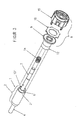
Figuren 2a, 2b und3 der beigefügten Zeichnungen dargestellt. - Der Rohrantrieb, wie ihn die
Figur 2a zeigt, umfasst einen Motor 1 mit einem Rotor 2, der eine Vielzahl Rotorbleche 3 umfasst. Der Rotor 2 ist fest auf einer Welle 4 montiert. An der einen Stirnseite des Rotors 2 ist ein zusätzliches Umlenkteil 5 vorgesehen, das fest mit dem Rotor 2 vergossen ist. - Das Umlenkteil 5, das mit dem Rotor 2 fest vergossen ist, ist in einer vergrößerten Darstellung in
Figur 2b gezeigt. Dieses Umlenkteil 5 enthält einen Kurzschlussring, der mit dem Bezugszeichen 6 bezeichnet ist. - Die eine Seite der Welle 4 ist derart verlängert, dass an diesem Wellenabschnitt 7 eine Bremseinheit 8 angeordnet werden kann. Diese Bremseinheit 8 besteht aus einer Bremsscheibe 9, einem dazu zugeordneten Reibbelag 10 sowie einem Lagerteil 11.
- Die Bremsscheibe 9 weist an ihrem dem Rotor 2 bzw. dem Umlenkteil 5 zugewandten Ende ein Metallteil 12 auf, mit dem sich die Bremsscheibe 9 gegen die Stirnseite des Umlenkteils 5 anlegt. Schließlich ist eine Ringnut 13, die zwischen der Welle 7 und einer inneren Ringfläche des Umlenkteils 5 gebildet ist, vorgesehen, in die sich der Endbereich einer Feder 14, die über den Wellenabschnitt 7 der Welle 4 geschoben ist, einlegt.
- Um diese Einheit zusammenzubauen, wird, nachdem die Feder 14 auf den Wellenabschnitt 7 aufgeschoben ist, die Bremsscheibe 9 mit dem Reibbelag 10 lose über dem Wellenabschnitt 7 geführt, bis sie an der Feder 14 anschlägt. Danach wird das Lagerteil 11 auf die Welle 4 aufgedrückt. Beim Aufdrücken des Lagerteils 11 stößt das Lagerteil 11 gegen den Reibbelag 10 und die Bremsscheibe 9 an. Wird diese Bremseinheit 8 weiter in Richtung des Umlenkteils 5 gedrückt, wird die Feder 14 zunehmend gespannt und das Metallteil 12 der Bremsscheibe 9 wandert in Richtung des Umlenkteils 5. Die Bremseinheit 8 wird so lange weiter in Richtung des Umlenkteils 5 gedrückt, bis sich zwischen dem Metallteil 12 und dem Umlenkteil 5 ein Luftspalt von ca. 0,3 mm ergibt. In dieser Position ist die Montage der Bremseinheit 8 an dem Wellenabschnitt 7 der Welle 4 abgeschlossen.
- Der so aufgebaute Rohrantrieb arbeitet wie folgt. Wenn an den Motor 1 Spannung angelegt wird, fließt im Rotor 2 ein großer Strom. Der in dem Kurzschlussring 6, der unter dem Umlenkteil 5 liegt, fließende Strom verursacht im Umlenkteil 5 ein Magnetfeld. Dieses Magnetfeld zieht das Metallteil 12 an und trennt somit die Bremsscheibe 9 von dem Lagerteil 11 und löst den reibenden Eingriff des Reibbelags 10 von dem Lagerteil 11. Wird der Motor 1 wieder abgeschaltet, so wird der Stromfluss unterbrochen. Das Magnetfeld am Umlenkteil 5 bricht zusammen und die Bremsscheibe 9 wird unter dem Druck der Feder 14 mit ihrem Reibbelag 10 gegen das Lagerteil 11 gedrückt, so dass eine weitere Drehung des nicht dargestellten Antriebsrohrs, in das der Motor 1 mit der Bremseinheit 8 eingesetzt ist, verhindert wird.
- Bei dieser Lösung erzeugt das Magnetfeld am Umlenkteil 5 eine starke Magnetkraft, wodurch hohe Bremskräfte erreicht werden können. Nachteilig bei dieser Lösung ist allerdings, dass bei der Fertigung des Rotors 2 das Umlenkteil 5 mit eingegossen werden muss. Dieses Erfordernis verursacht einen zusätzlichen Arbeitsaufwand und Kosten für das erforderliche Material.
- Ein weiterer Rohrantrieb ist schematisch in
Figur 3 dargestellt. Der Aufbau entspricht im Wesentlichen demjenigen, der inFigur 2a dargestellt ist. Daher sind für Bauteile, die denjenigen entsprechen, wie sie inFigur 1 dargestellt und beschrieben sind, entsprechende Bezugszeichen verwendet. - Im Gegensatz zu der Ausführungsform der
Figur 2a entfällt bei dem Aufbau, wie er inFigur 3 gezeigt ist, das Umlenkteil 5. Weiterhin ist das Lagerteil 11 der Ausführungsform inFigur 2a in der Ausführungsform derFigur 3 durch ein Lagerschild 15 ersetzt. Die magnetische Kraft zum Anziehen des Metallteils 12 wird durch einen Kurzschlussring 6' und das Rotorblech 3' realisiert. Dieser geänderte Kurzschlussring 6' ist so zentrisch um den Wellenabschnitt 7 angeordnet, dass wiederum eine Ringnut 13', vergleichbar mit der Ringnut 13 der Ausführungsform derFigur 2a , gebildet ist. Der Vorteil dieser Lösung besteht darin, dass kein zusätzliches Umlenkteil benötigt wird. Allerdings zeigt sich, dass bei diesem Aufbau derFigur 3 die erzeugte Magnetkraft gering ist. Folglich ergibt sich eine nur sehr kleine Bremswirkung, die in vielen Anwendungsfällen nicht ausreichend ist, gerade wenn massive und folglich schwere Rollläden oder Rolltore betätigt werden sollen. Folglich ist das inFigur 3 gezeigte Beispiel nur dann einsetzbar, wenn die anwendungsspezifischen, auftretenden Drehmomente klein sind. - Der vorliegenden Erfindung liegt nun die Aufgabe zugrunde, einen Rohrantrieb, wie er vorstehend beschrieben ist, so weiterzubilden, dass er bei vergleichbaren Abmessungen des Motors auch für Anwendungen mit höheren erforderlichen Drehmomenten einsetzbar ist.
- Diese Aufgabe wird durch einen Rohrantrieb mit den Merkmalen des Anspruchs 1 gelöst. Bevorzugte Ausführungsformen sind den abhängigen Ansprüchen zu entnehmen.
- Wesentlich ist, dass in die ringförmige Nut, die zwischen Welle und Kurzschlussring gebildet ist, ein Strom leitender Einlegering vollständig eingefügt ist. Dieser Einlegering verstärkt die durch das Magnetfeld erzeugte magnetische Kraft, um die Bremse vom Lagerteil weg zu ziehen und damit eine Drehung des Rohrs, in das diese Antriebseinheit eingesetzt ist, freizugeben.
- Der Reibbelag, wie er vorstehend erwähnt ist, wirkt in der Einheit sowohl als Bremsbelag als auch als Kupplungsbelag. Darüber hinaus kann dieser Reibbelag fest mit der Bremsscheibe oder dem Lagerschild verbunden sein. Außerdem kann der erwähnte Reibbelag aus mehreren einzelnen Scheiben zusammengesetzt sein, die, um die Einheit zu bremsen, gegeneinander unter dem Druck der Feder gedrückt werden.
- Weiterhin umfasst der vorstehend erwähnte Rotor üblicherweise die Rotorbleche und ist mit Aluminium ausgegossen.
- Obwohl mit der erfindungsgemäßen Maßnahme nur ein kleiner, zusätzlicher Ring, als Kurzschlussring bezeichnet, erforderlich ist, können die Magnetkräfte, um die Teile der Bremseinheit zu lösen, so erhöht werden, dass die Verwendung von Federn mit größerer Federkraft möglich ist. Umgekehrt erzeugen solche Federn mit größerer Federkraft entsprechend höhere Kräfte, mit denen sie die Teile der Bremseinheit in Eingriff halten.
- Es hat sich gezeigt, dass für den Einlegering eine Länge von 2 bis 10 mm, bezogen auf einen Rotor, der einen Außendurchmesser von 15 bis 100 mm aufweist, ausreichend ist. Vorzugsweise sollte der Einlegering bei einem solchen Außendurchmesser des Rotors eine Länge von etwa 4 mm aufweisen.
- Der Kurzschlussring, wie er eingesetzt wird, ist im Rotor vergossen, besteht üblicherweise aus Aluminium und ist durch Vergießen mit den Alustegen des Rotors verbunden. Der Kurzschlussring steht in axialer Richtung so weit über das Ende des Rotorblechs vor, dass sich der Einlegering in die zwischen Welle und Kurzschlussring gebildete Ringnut in axialer Richtung vollständig einlegen kann.
- Der Einlegering und der Kurzschlussring können fest miteinander verbunden werden. Einlegering und Kurzschlussring sollten als gesonderte Teile ausgeführt sein, da ansonsten dann, wenn Einlegering und Kurzschlussring als ein entsprechend groß dimensionierter einteiliger Ring ausgeführt werden würden, dies einen wesentlichen Einfluss auf die Motoreigenschaften, wie zum Beispiel das Anzugsmoment, haben könnte. Dadurch, dass Einlegering und Kurzschlussring als zwei Teile ausgeführt sind, die gegebenenfalls fest miteinander verbunden sind, bleiben die ursprünglichen Motoreigenschaften erhalten, die ohne den Einlegering gegeben wären.
- Um die Anzahl der erforderlichen Bauteile gering zu halten, könnte der Einlegering Teil der Feder sein. Der Einlegering könnte hierzu durch die erste Windung der Feder gebildet werden. Die Windungen der Feder, die die Federkraft bereitstellen sollen, könnten entsprechend aus dünnerem Material gewickelt sein.
- Um eine optimale Federwirkung zu erreichen, und im Hinblick auf eine lange Haltbarkeit der Feder, sollten für die Federn Materialien wie CuZn, CuBe und CuSn verwendet werden.
- Für die Feder wird vorzugsweise eine Schraubendruckfeder eingesetzt. Grundsätzlich sind aber auch andere Federtypen für die Feder möglich. Eine relativ kleine Federkraft lässt sich allerdings am einfachsten mit einer Schraubenfeder erzeugen, so dass dieser Federtyp bevorzugt zu verwenden ist.
- Die erfindungsgemäße Ausführungsform des Rohrantriebs wird nachfolgend anhand der
Figur 1 der Zeichnung beschrieben. - In den einzelnen Figuren der Zeichnungen zeigen
- Figur 1
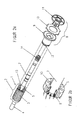
- die erfindungsgemäße Ausgestaltung eines Rohrantriebs,
- Figur 2
- eine erste Ausführung eines Rohrantriebs mit Bremseinheit nach dem Stand der Technik und
- Figur 3
- eine zweite Ausführung eines Rohrantriebs mit Bremseinheit, um im Vergleich dazu die erfindungsgemäßen Maßnahmen, wie sie in
Figur 1 gezeigt sind, darzustellen. - Da die
Figuren 2 und3 bereits in der Beschreibungseinleitung beschrieben wurden, wird nachfolgend nur der erfindungsgemäße Rohrantrieb, wie er inFigur 1 gezeigt ist, näher erläutert. - Der Rohrantrieb, wie ihn die
Figur 1 zeigt, umfasst den Motor 1 mit Rotor 2 und Rotorblech 3, die Welle 4 und den Kurzschlussring 6'. Auch ist eine Ringnut 13' zwischen dem Wellenabschnitt 7 der Welle 4 und dem Kurzschlussring 6' ausgebildet. - Die Bremseinheit 8 umfasst, entsprechend der Ausführungsform der
Figur 3 , eine Bremsscheibe 9, einen Bremsbelag 10 sowie ein Lagerschild 15. An dem dem Rotor 2 zugewandten Ende ist an der Bremsscheibe 9 ein Metallteil 12 angeordnet, das sich über den Kurzschlussring 6' schiebt. Wesentlich bei dieser Ausführungsform ist, dass ein zusätzlicher Einlegering 16 in die Ringnut 13' zwischen dem Kurzschlussring 6' und dem Wellenabschnitt 7 der Motorwelle 4 vollständig eingelegt ist. Dieser Einlegering 16 verstärkt den Stromfluss im eingeschalteten Zustand des Motors. Im Rotorblech 3' wird folglich ein stärkeres Magnetfeld erzeugt, das das Metallteil 12 anzieht. Dieser Aufbau hat den Vorteil, dass, vergleicht man mit der Ausführungsform derFigur 2a , kein zusätzliches Umlenkteil 5, wie es inFigur 2a gezeigt ist, im Rotor 2 eingegossen werden muss. Dieser zusätzliche Einlegering 16 ist darüber hinaus sehr leicht zu montieren. Durch diese Maßnahme wird aber ein Magnetfeld in einer Stärke erhalten, das dem Magnetfeld entspricht, wie es in der Anordnung derFigur 2a erreicht werden kann. -
- 1
- Motor
- 2
- Rotor
- 3, 3'
- Rotorblech
- 4
- Welle
- 5
- Umlenkteil
- 6, 6'
- Kurzschlussring
- 7
- Wellenabschnitt
- 8
- Bremseinheit
- 9
- Bremsscheibe
- 10
- Reibbelag
- 11
- Lagerteil
- 12
- Metallteil
- 13, 13'
- Ringnut
- 14
- Feder
Claims (9)
- Rohrantrieb mit einem Motor, der einen drehfest auf einer Welle angeordneten Rotor, der Rotorbleche und einen Kurzschlussring umfasst, aufweist, sowie mit einer der einen Stirnseite des Rotors zugeordneten Bremseinheit, die zentrisch auf der Welle angeordnet ist, wobei der Kurzschlussring die Welle umgibt und an dieser einen Stirnseite des Rotors angeordnet ist,
wobei die Bremseinheit eine Bremsscheibe sowie einen dazu zugeordneten Reibbelag und ein sich auf der anderen Seite des Reibbelags anlegendes Lagerschild, das eine Drehmomentstütze bildet, aufweist,
wobei mindestens eine Feder, die sich an der Stirnseite des Rotors abstützt, eine Kraft auf die Bremsscheibe ausübt und somit den Reibbelag zwischen Bremsscheibe und Lagerschild klemmend hält, und
wobei die Bremsscheibe ein Metallteil aufweist, das dann, wenn unter Betätigung des Motors in dem Rotor Strom fließt, die Bremsscheibe zu dem Rotor durch das sich im Rotor aufbauende Magnetfeld gezogen wird und dadurch der Reibbelag zwischen Bremsscheibe und Lagerschild freigegeben wird,
dadurch gekennzeichnet, dass in eine ringförmige Nut (13'), die zwischen Welle (4) und Kurzschlussring (6') gebildet ist, ein Strom leitender Einlegering (16) vollständig eingefügt ist. - Rohrantrieb nach Anspruch 1, dadurch gekennzeichnet, dass der Einlegering (16) eine Länge von 2 bis 10 mm aufweist, bezogen auf einen Rotor (2), der einen Außendurchmesser von 15 bis 100 mm aufweist.
- Rohrantrieb nach Anspruch 2, dadurch gekennzeichnet, dass der Einlegering (16) eine Länge von etwa 4 mm aufweist.
- Rohrantrieb nach einem der Ansprüche 1 bis 3, dadurch gekennzeichnet, dass der Einlegering (16) und der Kurzschlussring (6') fest miteinander verbunden sind.
- Rohrantrieb nach einem der Ansprüche 1 bis 4, dadurch gekennzeichnet, dass der Einlegering (16) Teil der Feder (14) ist.
- Rohrantrieb nach Anspruch 5, dadurch gekennzeichnet, dass der Einlegering (16) durch die erste Windung der Feder (14) gebildet ist.
- Rohrantrieb nach einem der Ansprüche 1 bis 5, dadurch gekennzeichnet, dass die Feder (14) aus CuZn gefertigt ist.
- Rohrantrieb nach einem der Ansprüche 1 bis 5, dadurch gekennzeichnet, dass die Feder (14) aus CuBe gefertigt ist.
- Rohrantrieb nach einem der Ansprüche 1 bis 5, dadurch gekennzeichnet, dass die Feder (14) aus CuSn gefertigt ist.
Applications Claiming Priority (1)
| Application Number | Priority Date | Filing Date | Title |
|---|---|---|---|
| DE102009004931A DE102009004931A1 (de) | 2009-01-16 | 2009-01-16 | Rohrantrieb |
Publications (3)
| Publication Number | Publication Date |
|---|---|
| EP2209187A2 EP2209187A2 (de) | 2010-07-21 |
| EP2209187A3 EP2209187A3 (de) | 2011-12-07 |
| EP2209187B1 true EP2209187B1 (de) | 2013-03-27 |
Family
ID=42077825
Family Applications (1)
| Application Number | Title | Priority Date | Filing Date |
|---|---|---|---|
| EP10000262A Active EP2209187B1 (de) | 2009-01-16 | 2010-01-13 | Rohrantrieb |
Country Status (2)
| Country | Link |
|---|---|
| EP (1) | EP2209187B1 (de) |
| DE (1) | DE102009004931A1 (de) |
Families Citing this family (2)
| Publication number | Priority date | Publication date | Assignee | Title |
|---|---|---|---|---|
| CN102882309B (zh) * | 2012-09-26 | 2014-10-01 | 宁波杜亚机电技术有限公司 | 手动管状电机 |
| CN103532296B (zh) * | 2013-10-24 | 2015-12-23 | 宁波市海誉机电科技有限公司 | 管状电机刹车组件 |
Family Cites Families (6)
| Publication number | Priority date | Publication date | Assignee | Title |
|---|---|---|---|---|
| DE4341889A1 (de) * | 1993-12-08 | 1995-06-14 | Siemens Ag | Kurzschlußläufermotor mit einer stirnseitig angebauten, elektromagnetisch lüftbaren Federdruckbremse |
| FR2724505A1 (fr) * | 1994-07-11 | 1996-03-15 | Plumer Sa | Moteur frein comprenant un moteur asynchrone et un frein fonctionnant par manque de courant |
| DE19522622C2 (de) | 1995-06-22 | 2003-07-10 | Becker Antriebe Gmbh | Vorrichtung zur Steuerung eines motorischen Antriebs |
| HU223767B1 (hu) * | 1999-12-09 | 2005-01-28 | Pál Kiss | Belső fékes elrendezés kis teljesítményű aszinkron motorokhoz |
| CN1510818A (zh) * | 2002-12-24 | 2004-07-07 | 苏州宝时得电动工具有限公司 | 带有转子制动机构的电动机 |
| CN1510817A (zh) * | 2002-12-24 | 2004-07-07 | 苏州宝时得电动工具有限公司 | 带制动装置的电动机 |
-
2009
- 2009-01-16 DE DE102009004931A patent/DE102009004931A1/de not_active Withdrawn
-
2010
- 2010-01-13 EP EP10000262A patent/EP2209187B1/de active Active
Also Published As
| Publication number | Publication date |
|---|---|
| DE102009004931A1 (de) | 2010-09-16 |
| EP2209187A2 (de) | 2010-07-21 |
| EP2209187A3 (de) | 2011-12-07 |
Similar Documents
| Publication | Publication Date | Title |
|---|---|---|
| EP2679865B2 (de) | Baureihe von Antriebseinrichtungen | |
| EP3997363B1 (de) | Stellantrieb mit einer drehmomentbegrenzungsvorrichtung | |
| EP2284414B1 (de) | Flüssigkeitsreibungskupplung | |
| EP2523835B1 (de) | Antrieb zur betätigung einer feststellbremse | |
| DE202014002459U1 (de) | Scheibenbremse und Bremsbetätigungsmechanismus für eine Scheibenbremse | |
| DE102010038418A1 (de) | Elektrische Bremse | |
| DE102009033394A1 (de) | Pneumatisch oder elektromechanisch betätigbare Scheibenbremse | |
| DE102015001647B4 (de) | Bremsanordnung | |
| DE102009042806A1 (de) | Pedalanordnung zur Kupplungsbetätigung | |
| DE102009026626A1 (de) | Kupplung oder Bremse in oder an einem Getriebe | |
| DE102012016735B4 (de) | Scheibenbremse, insbesondere für Nutzfahrzeuge | |
| EP2209187A2 (de) | Rohrantrieb | |
| DE2901784C2 (de) | Nachstellvorrichtung für den Luftspalt einer elektromagnetisch betätigbaren Scheibenbremse | |
| DE19719990A1 (de) | Bremse für einen Elektromotor | |
| DE2659457A1 (de) | Elektrische antriebsvorrichtung fuer jalousien | |
| DE19848584B4 (de) | Selbstverstärkende Reibungskupplung | |
| DE2510390C3 (de) | Mit der Zugkraft einer Elektro-Magnetbremse lösbare Federdruckkupplung | |
| EP3760892B1 (de) | Lamellenbremse für einen fahrzeugantrieb und ein fahrzeugantrieb | |
| DE102015121707A1 (de) | Elektromagnetische Stellvorrichtung sowie Stellsystem | |
| DE102014217277A1 (de) | Doppelkupplung | |
| DE102012020765A1 (de) | Elektromagnetisch betätigte Bremse | |
| DE69610009T2 (de) | Steuervorrichtung mit Elektromagnet mit Kern ohne Reibung und Verwendung bei Ventilen mit Kontinusteuerung | |
| DE102010019317A1 (de) | Rotor für einen Permanentmagnetretarder | |
| DE102014217279A1 (de) | Doppelkupplung | |
| DE102016213218B4 (de) | Kupplungseinrichtung |
Legal Events
| Date | Code | Title | Description |
|---|---|---|---|
| PUAI | Public reference made under article 153(3) epc to a published international application that has entered the european phase |
Free format text: ORIGINAL CODE: 0009012 |
|
| AK | Designated contracting states |
Kind code of ref document: A2 Designated state(s): AT BE BG CH CY CZ DE DK EE ES FI FR GB GR HR HU IE IS IT LI LT LU LV MC MK MT NL NO PL PT RO SE SI SK SM TR |
|
| AX | Request for extension of the european patent |
Extension state: AL BA RS |
|
| PUAL | Search report despatched |
Free format text: ORIGINAL CODE: 0009013 |
|
| AK | Designated contracting states |
Kind code of ref document: A3 Designated state(s): AT BE BG CH CY CZ DE DK EE ES FI FR GB GR HR HU IE IS IT LI LT LU LV MC MK MT NL NO PL PT RO SE SI SK SM TR |
|
| AX | Request for extension of the european patent |
Extension state: AL BA RS |
|
| RIC1 | Information provided on ipc code assigned before grant |
Ipc: H02K 7/104 20060101AFI20111028BHEP Ipc: H02K 7/102 20060101ALI20111028BHEP |
|
| 17P | Request for examination filed |
Effective date: 20120426 |
|
| GRAP | Despatch of communication of intention to grant a patent |
Free format text: ORIGINAL CODE: EPIDOSNIGR1 |
|
| GRAS | Grant fee paid |
Free format text: ORIGINAL CODE: EPIDOSNIGR3 |
|
| GRAA | (expected) grant |
Free format text: ORIGINAL CODE: 0009210 |
|
| AK | Designated contracting states |
Kind code of ref document: B1 Designated state(s): AT BE BG CH CY CZ DE DK EE ES FI FR GB GR HR HU IE IS IT LI LT LU LV MC MK MT NL NO PL PT RO SE SI SK SM TR |
|
| REG | Reference to a national code |
Ref country code: GB Ref legal event code: FG4D Free format text: NOT ENGLISH |
|
| REG | Reference to a national code |
Ref country code: CH Ref legal event code: EP |
|
| REG | Reference to a national code |
Ref country code: AT Ref legal event code: REF Ref document number: 603942 Country of ref document: AT Kind code of ref document: T Effective date: 20130415 |
|
| REG | Reference to a national code |
Ref country code: IE Ref legal event code: FG4D Free format text: LANGUAGE OF EP DOCUMENT: GERMAN |
|
| REG | Reference to a national code |
Ref country code: DE Ref legal event code: R096 Ref document number: 502010002659 Country of ref document: DE Effective date: 20130523 |
|
| PG25 | Lapsed in a contracting state [announced via postgrant information from national office to epo] |
Ref country code: BG Free format text: LAPSE BECAUSE OF FAILURE TO SUBMIT A TRANSLATION OF THE DESCRIPTION OR TO PAY THE FEE WITHIN THE PRESCRIBED TIME-LIMIT Effective date: 20130627 Ref country code: LT Free format text: LAPSE BECAUSE OF FAILURE TO SUBMIT A TRANSLATION OF THE DESCRIPTION OR TO PAY THE FEE WITHIN THE PRESCRIBED TIME-LIMIT Effective date: 20130327 Ref country code: SE Free format text: LAPSE BECAUSE OF FAILURE TO SUBMIT A TRANSLATION OF THE DESCRIPTION OR TO PAY THE FEE WITHIN THE PRESCRIBED TIME-LIMIT Effective date: 20130327 Ref country code: NO Free format text: LAPSE BECAUSE OF FAILURE TO SUBMIT A TRANSLATION OF THE DESCRIPTION OR TO PAY THE FEE WITHIN THE PRESCRIBED TIME-LIMIT Effective date: 20130627 |
|
| REG | Reference to a national code |
Ref country code: NL Ref legal event code: T3 |
|
| REG | Reference to a national code |
Ref country code: LT Ref legal event code: MG4D |
|
| PG25 | Lapsed in a contracting state [announced via postgrant information from national office to epo] |
Ref country code: SI Free format text: LAPSE BECAUSE OF FAILURE TO SUBMIT A TRANSLATION OF THE DESCRIPTION OR TO PAY THE FEE WITHIN THE PRESCRIBED TIME-LIMIT Effective date: 20130327 Ref country code: GR Free format text: LAPSE BECAUSE OF FAILURE TO SUBMIT A TRANSLATION OF THE DESCRIPTION OR TO PAY THE FEE WITHIN THE PRESCRIBED TIME-LIMIT Effective date: 20130628 Ref country code: FI Free format text: LAPSE BECAUSE OF FAILURE TO SUBMIT A TRANSLATION OF THE DESCRIPTION OR TO PAY THE FEE WITHIN THE PRESCRIBED TIME-LIMIT Effective date: 20130327 Ref country code: LV Free format text: LAPSE BECAUSE OF FAILURE TO SUBMIT A TRANSLATION OF THE DESCRIPTION OR TO PAY THE FEE WITHIN THE PRESCRIBED TIME-LIMIT Effective date: 20130327 |
|
| PG25 | Lapsed in a contracting state [announced via postgrant information from national office to epo] |
Ref country code: HR Free format text: LAPSE BECAUSE OF FAILURE TO SUBMIT A TRANSLATION OF THE DESCRIPTION OR TO PAY THE FEE WITHIN THE PRESCRIBED TIME-LIMIT Effective date: 20130327 |
|
| PG25 | Lapsed in a contracting state [announced via postgrant information from national office to epo] |
Ref country code: EE Free format text: LAPSE BECAUSE OF FAILURE TO SUBMIT A TRANSLATION OF THE DESCRIPTION OR TO PAY THE FEE WITHIN THE PRESCRIBED TIME-LIMIT Effective date: 20130327 Ref country code: SK Free format text: LAPSE BECAUSE OF FAILURE TO SUBMIT A TRANSLATION OF THE DESCRIPTION OR TO PAY THE FEE WITHIN THE PRESCRIBED TIME-LIMIT Effective date: 20130327 Ref country code: PT Free format text: LAPSE BECAUSE OF FAILURE TO SUBMIT A TRANSLATION OF THE DESCRIPTION OR TO PAY THE FEE WITHIN THE PRESCRIBED TIME-LIMIT Effective date: 20130729 Ref country code: ES Free format text: LAPSE BECAUSE OF FAILURE TO SUBMIT A TRANSLATION OF THE DESCRIPTION OR TO PAY THE FEE WITHIN THE PRESCRIBED TIME-LIMIT Effective date: 20130708 Ref country code: IS Free format text: LAPSE BECAUSE OF FAILURE TO SUBMIT A TRANSLATION OF THE DESCRIPTION OR TO PAY THE FEE WITHIN THE PRESCRIBED TIME-LIMIT Effective date: 20130727 Ref country code: RO Free format text: LAPSE BECAUSE OF FAILURE TO SUBMIT A TRANSLATION OF THE DESCRIPTION OR TO PAY THE FEE WITHIN THE PRESCRIBED TIME-LIMIT Effective date: 20130327 Ref country code: CZ Free format text: LAPSE BECAUSE OF FAILURE TO SUBMIT A TRANSLATION OF THE DESCRIPTION OR TO PAY THE FEE WITHIN THE PRESCRIBED TIME-LIMIT Effective date: 20130327 |
|
| PG25 | Lapsed in a contracting state [announced via postgrant information from national office to epo] |
Ref country code: PL Free format text: LAPSE BECAUSE OF FAILURE TO SUBMIT A TRANSLATION OF THE DESCRIPTION OR TO PAY THE FEE WITHIN THE PRESCRIBED TIME-LIMIT Effective date: 20130327 Ref country code: CY Free format text: LAPSE BECAUSE OF FAILURE TO SUBMIT A TRANSLATION OF THE DESCRIPTION OR TO PAY THE FEE WITHIN THE PRESCRIBED TIME-LIMIT Effective date: 20130327 |
|
| PG25 | Lapsed in a contracting state [announced via postgrant information from national office to epo] |
Ref country code: DK Free format text: LAPSE BECAUSE OF FAILURE TO SUBMIT A TRANSLATION OF THE DESCRIPTION OR TO PAY THE FEE WITHIN THE PRESCRIBED TIME-LIMIT Effective date: 20130327 |
|
| PLBE | No opposition filed within time limit |
Free format text: ORIGINAL CODE: 0009261 |
|
| STAA | Information on the status of an ep patent application or granted ep patent |
Free format text: STATUS: NO OPPOSITION FILED WITHIN TIME LIMIT |
|
| PG25 | Lapsed in a contracting state [announced via postgrant information from national office to epo] |
Ref country code: IT Free format text: LAPSE BECAUSE OF FAILURE TO SUBMIT A TRANSLATION OF THE DESCRIPTION OR TO PAY THE FEE WITHIN THE PRESCRIBED TIME-LIMIT Effective date: 20130327 |
|
| 26N | No opposition filed |
Effective date: 20140103 |
|
| REG | Reference to a national code |
Ref country code: DE Ref legal event code: R097 Ref document number: 502010002659 Country of ref document: DE Effective date: 20140103 |
|
| PG25 | Lapsed in a contracting state [announced via postgrant information from national office to epo] |
Ref country code: MC Free format text: LAPSE BECAUSE OF FAILURE TO SUBMIT A TRANSLATION OF THE DESCRIPTION OR TO PAY THE FEE WITHIN THE PRESCRIBED TIME-LIMIT Effective date: 20130327 Ref country code: LU Free format text: LAPSE BECAUSE OF FAILURE TO SUBMIT A TRANSLATION OF THE DESCRIPTION OR TO PAY THE FEE WITHIN THE PRESCRIBED TIME-LIMIT Effective date: 20140113 |
|
| REG | Reference to a national code |
Ref country code: CH Ref legal event code: PL |
|
| GBPC | Gb: european patent ceased through non-payment of renewal fee |
Effective date: 20140113 |
|
| PG25 | Lapsed in a contracting state [announced via postgrant information from national office to epo] |
Ref country code: CH Free format text: LAPSE BECAUSE OF NON-PAYMENT OF DUE FEES Effective date: 20140131 Ref country code: LI Free format text: LAPSE BECAUSE OF NON-PAYMENT OF DUE FEES Effective date: 20140131 |
|
| REG | Reference to a national code |
Ref country code: IE Ref legal event code: MM4A |
|
| PG25 | Lapsed in a contracting state [announced via postgrant information from national office to epo] |
Ref country code: GB Free format text: LAPSE BECAUSE OF NON-PAYMENT OF DUE FEES Effective date: 20140113 |
|
| PG25 | Lapsed in a contracting state [announced via postgrant information from national office to epo] |
Ref country code: IE Free format text: LAPSE BECAUSE OF NON-PAYMENT OF DUE FEES Effective date: 20140113 |
|
| REG | Reference to a national code |
Ref country code: FR Ref legal event code: PLFP Year of fee payment: 7 |
|
| PG25 | Lapsed in a contracting state [announced via postgrant information from national office to epo] |
Ref country code: MT Free format text: LAPSE BECAUSE OF FAILURE TO SUBMIT A TRANSLATION OF THE DESCRIPTION OR TO PAY THE FEE WITHIN THE PRESCRIBED TIME-LIMIT Effective date: 20130327 |
|
| REG | Reference to a national code |
Ref country code: AT Ref legal event code: MM01 Ref document number: 603942 Country of ref document: AT Kind code of ref document: T Effective date: 20150113 |
|
| PG25 | Lapsed in a contracting state [announced via postgrant information from national office to epo] |
Ref country code: SM Free format text: LAPSE BECAUSE OF FAILURE TO SUBMIT A TRANSLATION OF THE DESCRIPTION OR TO PAY THE FEE WITHIN THE PRESCRIBED TIME-LIMIT Effective date: 20130327 |
|
| PG25 | Lapsed in a contracting state [announced via postgrant information from national office to epo] |
Ref country code: AT Free format text: LAPSE BECAUSE OF NON-PAYMENT OF DUE FEES Effective date: 20150113 |
|
| PG25 | Lapsed in a contracting state [announced via postgrant information from national office to epo] |
Ref country code: HU Free format text: LAPSE BECAUSE OF FAILURE TO SUBMIT A TRANSLATION OF THE DESCRIPTION OR TO PAY THE FEE WITHIN THE PRESCRIBED TIME-LIMIT; INVALID AB INITIO Effective date: 20100113 |
|
| REG | Reference to a national code |
Ref country code: FR Ref legal event code: PLFP Year of fee payment: 8 |
|
| REG | Reference to a national code |
Ref country code: FR Ref legal event code: PLFP Year of fee payment: 9 |
|
| PG25 | Lapsed in a contracting state [announced via postgrant information from national office to epo] |
Ref country code: MK Free format text: LAPSE BECAUSE OF FAILURE TO SUBMIT A TRANSLATION OF THE DESCRIPTION OR TO PAY THE FEE WITHIN THE PRESCRIBED TIME-LIMIT Effective date: 20130327 |
|
| P01 | Opt-out of the competence of the unified patent court (upc) registered |
Effective date: 20230530 |
|
| PGFP | Annual fee paid to national office [announced via postgrant information from national office to epo] |
Ref country code: NL Payment date: 20260121 Year of fee payment: 17 |
|
| PGFP | Annual fee paid to national office [announced via postgrant information from national office to epo] |
Ref country code: DE Payment date: 20260131 Year of fee payment: 17 |
|
| PGFP | Annual fee paid to national office [announced via postgrant information from national office to epo] |
Ref country code: BE Payment date: 20260121 Year of fee payment: 17 |
|
| PGFP | Annual fee paid to national office [announced via postgrant information from national office to epo] |
Ref country code: FR Payment date: 20260123 Year of fee payment: 17 |
|
| PGFP | Annual fee paid to national office [announced via postgrant information from national office to epo] |
Ref country code: TR Payment date: 20260112 Year of fee payment: 17 |