EP2208963B1 - Method for measuring gaps and flushes - Google Patents
Method for measuring gaps and flushes Download PDFInfo
- Publication number
- EP2208963B1 EP2208963B1 EP09179332A EP09179332A EP2208963B1 EP 2208963 B1 EP2208963 B1 EP 2208963B1 EP 09179332 A EP09179332 A EP 09179332A EP 09179332 A EP09179332 A EP 09179332A EP 2208963 B1 EP2208963 B1 EP 2208963B1
- Authority
- EP
- European Patent Office
- Prior art keywords
- cameras
- image
- images
- measured
- clearance
- Prior art date
- Legal status (The legal status is an assumption and is not a legal conclusion. Google has not performed a legal analysis and makes no representation as to the accuracy of the status listed.)
- Active
Links
- 238000000034 method Methods 0.000 title claims abstract description 20
- 238000012935 Averaging Methods 0.000 claims description 9
- 230000003287 optical effect Effects 0.000 claims description 7
- 238000012937 correction Methods 0.000 claims description 3
- 238000005286 illumination Methods 0.000 claims 1
- 238000005259 measurement Methods 0.000 description 19
- 238000004364 calculation method Methods 0.000 description 6
- 238000004519 manufacturing process Methods 0.000 description 6
- 239000006185 dispersion Substances 0.000 description 4
- 238000005516 engineering process Methods 0.000 description 4
- 238000000926 separation method Methods 0.000 description 3
- 238000009825 accumulation Methods 0.000 description 2
- 238000000691 measurement method Methods 0.000 description 2
- 238000012545 processing Methods 0.000 description 2
- 238000004458 analytical method Methods 0.000 description 1
- 238000010276 construction Methods 0.000 description 1
- 238000007796 conventional method Methods 0.000 description 1
- 238000001514 detection method Methods 0.000 description 1
- 238000010586 diagram Methods 0.000 description 1
- 230000006870 function Effects 0.000 description 1
- 238000003384 imaging method Methods 0.000 description 1
- 238000007689 inspection Methods 0.000 description 1
- 239000003550 marker Substances 0.000 description 1
- 230000013011 mating Effects 0.000 description 1
- 238000003032 molecular docking Methods 0.000 description 1
- 230000008447 perception Effects 0.000 description 1
- 238000011084 recovery Methods 0.000 description 1
Images


Classifications
-
- B—PERFORMING OPERATIONS; TRANSPORTING
- B62—LAND VEHICLES FOR TRAVELLING OTHERWISE THAN ON RAILS
- B62D—MOTOR VEHICLES; TRAILERS
- B62D65/00—Designing, manufacturing, e.g. assembling, facilitating disassembly, or structurally modifying motor vehicles or trailers, not otherwise provided for
- B62D65/005—Inspection and final control devices
-
- G—PHYSICS
- G01—MEASURING; TESTING
- G01B—MEASURING LENGTH, THICKNESS OR SIMILAR LINEAR DIMENSIONS; MEASURING ANGLES; MEASURING AREAS; MEASURING IRREGULARITIES OF SURFACES OR CONTOURS
- G01B11/00—Measuring arrangements characterised by the use of optical techniques
- G01B11/14—Measuring arrangements characterised by the use of optical techniques for measuring distance or clearance between spaced objects or spaced apertures
-
- G—PHYSICS
- G01—MEASURING; TESTING
- G01B—MEASURING LENGTH, THICKNESS OR SIMILAR LINEAR DIMENSIONS; MEASURING ANGLES; MEASURING AREAS; MEASURING IRREGULARITIES OF SURFACES OR CONTOURS
- G01B11/00—Measuring arrangements characterised by the use of optical techniques
- G01B11/24—Measuring arrangements characterised by the use of optical techniques for measuring contours or curvatures
- G01B11/25—Measuring arrangements characterised by the use of optical techniques for measuring contours or curvatures by projecting a pattern, e.g. one or more lines, moiré fringes on the object
- G01B11/2504—Calibration devices
-
- G—PHYSICS
- G06—COMPUTING; CALCULATING OR COUNTING
- G06T—IMAGE DATA PROCESSING OR GENERATION, IN GENERAL
- G06T7/00—Image analysis
- G06T7/50—Depth or shape recovery
- G06T7/55—Depth or shape recovery from multiple images
- G06T7/593—Depth or shape recovery from multiple images from stereo images
-
- G—PHYSICS
- G06—COMPUTING; CALCULATING OR COUNTING
- G06T—IMAGE DATA PROCESSING OR GENERATION, IN GENERAL
- G06T2207/00—Indexing scheme for image analysis or image enhancement
- G06T2207/10—Image acquisition modality
- G06T2207/10004—Still image; Photographic image
- G06T2207/10012—Stereo images
-
- G—PHYSICS
- G06—COMPUTING; CALCULATING OR COUNTING
- G06T—IMAGE DATA PROCESSING OR GENERATION, IN GENERAL
- G06T2207/00—Indexing scheme for image analysis or image enhancement
- G06T2207/30—Subject of image; Context of image processing
- G06T2207/30108—Industrial image inspection
- G06T2207/30164—Workpiece; Machine component
Definitions
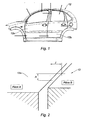
- the present invention relates to a measurement method intended more particularly for the measurement of clearances and outcrops between bodywork parts having respective edges vis-à-vis.
- Controlling the compliance of games and outcrops on motor vehicles is an important objective for manufacturers because it contributes significantly to the perception of the quality of manufacture of vehicles by end customers.
- the patent EP0845656 discloses a system for measuring games and outcropping by optical triangulation, projecting two parallel light planes on the parts to be characterized, to create two lines of highlighting.
- the patent US6529283 refers to a device designed to measure the width of a separation between two parts, this separation being delimited by an edge of each of the two parts. The principle is based on a light irradiation of this separation zone, then on the recovery of the light reflected by said edges, the light sources and the detection means of the reflected light being positioned in an optimized manner.
- Optical gaming and outcrop systems can use two types of vision technology, namely monovision triangulation technology or stereovision technology.
- the principle of vision measurement is based on the analysis of one or more images acquired with one or more cameras. Each trace on which it is desired to measure a clearance and outcropping is revealed by a lighting device that emits one or more laser light lines projected radially to the docking to be measured.
- the light emitting device and the camera are integrated in a housing to form a sensor.
- the angles between the different elements are predetermined by construction and make it possible to correct the play and flush values read on the acquired image in order to determine the true values of play and outcropping.
- the optical axis of the camera is necessarily inclined at a certain angle with respect to the lamellar luminous plane.
- the value of the outcrop seen by the camera must be corrected to determine the true value of said outcrop.
- the trace to be measured remains revealed by an additional lighting device, said trace being observed by two cameras with a small field of view, thus dedicated to a particular trace.
- the positioning of the cameras is custom-made, and requires the site to perform a calibration procedure for each pair of cameras.
- stereovision makes it possible to determine the three-dimensional coordinates of a point in the reference frame of the stereoscopic pair if the point considered is well seen by the two cameras.
- the value of said clearance and said outcropping is determined by distance calculation between these points.
- the conventional stereoscopic method greatly increases the measurement dispersion.
- the values of play and outcrop are distances, therefore relative measurements not determined by direct reading but derived from calculations from the absolute coordinates of the remarkable points.
- the measurement of the coordinates of the points being subjected to a measurement uncertainty.
- the calculation of the distance between the points thus causes the accumulation of these measurement inaccuracies on each coordinate of each point.
- the stereovision system requires two cameras per trace to be measured as well as an image acquisition synchronization system.
- At least two images are acquired using two cameras having different viewing angles and each capturing at least one image, the corresponding optical marker being that of each stereoscopic pair formed.
- a true value of the game and / or flush is obtained by averaging the two values from the two images acquired by a pair of cameras.
- each of the cameras acquires a plurality of images.
- a true value of the game and / or flush is obtained by averaging the values from this plurality of images.
- the field of view and the resolution of the cameras will be chosen so that several traces to be measured can be visible within the same image.
- images are acquired using at least three cameras forming at least three different stereoscopic pairs.
- images are acquired using at least four cameras forming at least six different stereoscopic pairs.
- the true values obtained are obtained by averaging values from different stereoscopic pairs, which themselves may or may not be obtained by averaging values from a plurality.
- a device for measuring play and outcropping by a vision method comprises a system adapted to measure play and outcropping on several openings and surfaces of a motor vehicle 12.
- the system is adapted to measure games and outcrops on the lateral opening of the vehicle 12, including the front 12a and 12b rear doors.
- gap measurement zones and outcrops are represented by solid lines intersecting the surfaces concerned.
- orientation and position terms used in the following description are in relation to the usual orientations of a vehicle.
- the system is fixed and comprises light line projection means 40, image pickup means 18, calculation means 16 and vehicle drive means 12 with respect to the light line projection means and means of taking pictures 14.
- the drive means are advantageously constituted by the assembly line itself, the elements of the measuring system being positioned around the latter in the manner of a gantry.
- the imaging means 18 are arranged along an arch under which the vehicle 12 scrolls and comprise a set of image sensors 18.
- the image sensors 18 are digital cameras with a wide field of view.
- the figure 5 illustrates the field of view of a camera 18.
- the resolution of each image sensor is greater than 4 Mpx and their intrinsic reliability is less than 75 microns.
- each camera 18 makes it possible to obtain at least one zone in which the fields of vision of at least two cameras 18 overlap at least partially (see FIG. figure 8 ), thus covering the same area in which at least one play and outcrop measurement is to be performed.
- the vehicle 12 is in a first position which allows the system 10 to measure the clearances and outcrops between the front part of the front door 12a and, for example, the front fender 22 and the bay upright 24.
- the light line projection means 40 are capable of projecting onto the surfaces considered at least one light line 26 intersecting substantially transversely the edges of these surfaces.
- the cameras 18 are capable of capturing at least two images of each light line 26 from two different angles of view.
- each light line 26 is seen by at least two separate image sensors 18.
- the fields of view of the four image sensors 18 arranged on the left side of the vehicle are represented by frames on the figure 8 .
- a processing module 34 of the computer 16 determines a value representative of the outcrop and a value of the set to be measured in the two-dimensional frame of the image.
- a calculation module 36 makes it possible to calculate the values of the gaps and outcrops according to the method that is the subject of the present invention.
- This light line 26 is interrupted at said interstice.
- Each camera 18 captures at least one image of this light line.
- the captured image ( figure 3 ) of the light line 26 concerned thus substantially has two line segments interrupted and offset at the gap.
- the alignment gap A 'between these two segments is representative of the outcrop while the horizontal gap J' between the line segments is representative of the set.
- the image processing module 34 of the computer 16 determines a value representative of the outcrop and a value of the set to be measured in the two-dimensional frame of the image.
- a calculation module 36 makes it possible to make these corrections and to determine the true values of the J & A's.
- the position and orientation coordinates of the corresponding camera are used in the local repository of the trace to be measured.
- each image captured from each camera 18 it is possible to express a true play value and a true outcrop value by applying a function of the spherical coordinates of position (r, ⁇ , ⁇ ) and of orientation ( ⁇ ) of said camera 18 applied to the set value and / or outcrop measured on the captured image.
- each camera 18 can acquire a multitude of images, the values of the games and outcrops obtained that can be averaged before or after correction in the corresponding optical mark.
- the measurement dispersion is further reduced by averaging the values obtained on the different acquisitions of images from the same stereoscopic pair.
Abstract
Description
La présente invention concerne un procédé de mesure destiné plus particulièrement à la mesure de jeux et d'affleurements entre des pièces de carrosserie présentant des bords respectifs en vis-à-vis.The present invention relates to a measurement method intended more particularly for the measurement of clearances and outcrops between bodywork parts having respective edges vis-à-vis.
La maîtrise de la conformité des jeux et affleurements sur les véhicules automobiles est un objectif important pour les constructeurs car elle contribue fortement à la perception de la qualité de fabrication des véhicules par les clients finaux.Controlling the compliance of games and outcrops on motor vehicles is an important objective for manufacturers because it contributes significantly to the perception of the quality of manufacture of vehicles by end customers.
Actuellement, afin de mesurer les jeux et affleurements, différentes technologies, vision notamment, sont mises en oeuvre. Des solutions utilisant des systèmes portables sont décrites dans les documents
Le brevet
Toutefois, l'utilisation de pistolets portables implique la réalisation des mesures en dehors du flux de production et ces systèmes s'avèrent peu pratiques pour une utilisation unitaire en ligne de production, et leur emploi est donc limité à des opérations de contrôle par prélèvement hors ligne de production.However, the use of portable guns means that measurements outside the workflow are required and these systems are not practical for unitary use in the production line, and their use is therefore limited to out-of-the-box control operations. production line.
Pour la réalisation de mesures automatiques et unitaires en ligne de production, il convient de recourir à des stations de mesures équipées de capteurs fixes ou de capteurs embarqués sur bras robots, par exemple.For the realization of automatic and unit measurements in the production line, it is necessary to resort to measurement stations equipped with fixed sensors or on-board sensors on robot arms, for example.
Les systèmes de mesure optique de jeux et affleurements peuvent utiliser deux types de technologie vision, à savoir une technologie monovision à triangulation ou une technologie de stéréovision.Optical gaming and outcrop systems can use two types of vision technology, namely monovision triangulation technology or stereovision technology.
Le principe de la mesure par vision repose sur l'analyse d'une ou plusieurs images acquises à l'aide d'une ou plusieurs caméras. Chaque trace sur laquelle on souhaite mesurer un jeu et affleurement est révélée par un dispositif d'éclairage qui émet une ou plusieurs raies de lumière laser projetées radialement à l'accostage à mesurer.The principle of vision measurement is based on the analysis of one or more images acquired with one or more cameras. Each trace on which it is desired to measure a clearance and outcropping is revealed by a lighting device that emits one or more laser light lines projected radially to the docking to be measured.
Sur le profil lumineux acquis sur une image donnée, un ensemble d'algorithmes va permettre de déterminer des points caractéristiques des segments du profil observé et une combinaison de projections permettra de quantifier les écarts représentant le jeu et l'affleurement.On the luminous profile acquired on a given image, a set of algorithms will make it possible to determine characteristic points of the segments of the observed profile and a combination of projections will make it possible to quantify the differences representing the play and the outcrop.
Dans un procédé monovision à triangulation, le dispositif d'émission de lumière et la caméra sont intégrés dans un boîtier de façon à former un capteur. Les angles entre les différents éléments sont prédéterminés par construction et permettent de corriger les valeurs de jeu et d'affleurement lus sur l'image acquise afin de déterminer les valeurs vraies de jeu et d'affleurement.In a monovision triangulation process, the light emitting device and the camera are integrated in a housing to form a sensor. The angles between the different elements are predetermined by construction and make it possible to correct the play and flush values read on the acquired image in order to determine the true values of play and outcropping.
En pratique, on s'efforce de positionner ledit capteur de manière telle que l'axe optique de la caméra soit sensiblement perpendiculaire à la trace formée par l'intersection des surfaces des pièces en accostage et le plan lumineux lamellaire. Ainsi, la valeur de jeu vu par la caméra est sensiblement égale à la valeur vraie dudit jeu.In practice, it is attempted to position said sensor so that the optical axis of the camera is substantially perpendicular to the trace formed by the intersection of the surfaces of the mating parts and the lamellar light plane. Thus, the game value seen by the camera is substantially equal to the true value of said game.
En revanche, l'axe optique de la caméra est nécessairement incliné d'un certain angle par rapport au plan lumineux lamellaire. De ce fait, la valeur de l'affleurement vu par la caméra doit être corrigée pour déterminer la valeur vraie dudit affleurement.On the other hand, the optical axis of the camera is necessarily inclined at a certain angle with respect to the lamellar luminous plane. As a result, the value of the outcrop seen by the camera must be corrected to determine the true value of said outcrop.
Dans un procédé classique de mesure par stéréovision, la trace à mesurer reste révélée par un dispositif d'éclairage additionnel, ladite trace étant observée par deux caméras à faible champ de vision, donc dédiées à une trace particulière.In a conventional method of measurement by stereovision, the trace to be measured remains revealed by an additional lighting device, said trace being observed by two cameras with a small field of view, thus dedicated to a particular trace.
De manière générale, le positionnement des caméras est réalisé à façon, et nécessite sur le site l'exécution d'une procédure de calibration pour chaque paire de caméras.In general, the positioning of the cameras is custom-made, and requires the site to perform a calibration procedure for each pair of cameras.
Dans son principe, la stéréovision permet de déterminer les coordonnées tridimensionnelles d'un point dans le référentiel de la paire stéréoscopique si le point considéré est bien vu par les deux caméras.In principle, stereovision makes it possible to determine the three-dimensional coordinates of a point in the reference frame of the stereoscopic pair if the point considered is well seen by the two cameras.
A partir des coordonnées tridimensionnelles calculées pour les points remarquables définissant le jeu et l'affleurement, on détermine par calcul de distance entre ces points, la valeur dudit jeu et dudit affleurement.From the three-dimensional coordinates calculated for the remarkable points defining the play and the outcropping, the value of said clearance and said outcropping is determined by distance calculation between these points.
Toutefois, le procédé stéréoscopique classique augmente grandement la dispersion de mesure. En effet, les valeurs de jeu et d'affleurement sont des distances, donc des mesures relatives non déterminées par lecture directe mais issues de calculs à partir des coordonnées absolues des points remarquables. La mesure des coordonnées des points étant soumise à une incertitude de mesure. Le calcul de la distance entre les points entraîne donc l'accumulation de ces imprécisions de mesures sur chaque coordonnée de chaque point.However, the conventional stereoscopic method greatly increases the measurement dispersion. Indeed, the values of play and outcrop are distances, therefore relative measurements not determined by direct reading but derived from calculations from the absolute coordinates of the remarkable points. The measurement of the coordinates of the points being subjected to a measurement uncertainty. The calculation of the distance between the points thus causes the accumulation of these measurement inaccuracies on each coordinate of each point.
Par ailleurs, on notera que le système par stéréovision nécessite deux caméras par trace à mesurer ainsi qu'un système de synchronisation d'acquisition d'images.Moreover, it will be noted that the stereovision system requires two cameras per trace to be measured as well as an image acquisition synchronization system.
Ainsi, il existe un besoin pour un procédé de mesure de jeu et affleurement fiable, donnant une faible incertitude de mesure et pouvant être utilisé sur une station implantée en ligne de production pour faire des mesures sur des véhicules en mouvement.Thus, there is a need for a reliable play and flush measurement method, giving low measurement uncertainty and which can be used on a station set up in the production line to make measurements on moving vehicles.
Pour ce faire, la présente invention se rapporte à un procédé de mesure de jeux et affleurements entre deux pièces présentant des bords respectifs en vis-à-vis, caractérisé en ce qu'il comprend les étapes suivantes visant à :
- projeter sur les surfaces des pièces au moins une ligne lumineuse coupant lesdits bords des pièces à l'emplacement de la trace à mesurer;
- acquérir au moins deux images de ladite ligne lumineuse à l'aide d'au moins une paire de caméras,
- sur chaque image acquise, déterminer directement ou indirectement la valeur représentative du jeu et/ou affleurement dans le repère deux dimensions correspondant de l'image, les lignes de bord de pièces pouvant avoir été préalablement déterminées à partir d'images acquises avec un éclairage diffus
- déterminer par procédé stéréoscopique la position de la trace à mesurer dans le référentiel d'une paire de caméras, puis en déduire la position et l'orientation de chacune des caméras de cette paire dans le référentiel local de la trace à mesurer
- corriger la valeur ainsi obtenue pour le jeu et/ou affleurement en fonction de la position et de l'orientation de chaque caméra dans le référentiel local du jeu et affleurement à mesurer de manière à obtenir une valeur vraie du jeu et/ou de l'affleurement.
- projecting on the surfaces of the pieces at least one light line intersecting said edges of the pieces at the location of the trace to be measured;
- acquiring at least two images of said light line using at least one pair of cameras,
- on each acquired image, directly or indirectly determine the representative value of the game and / or outcrop in the corresponding two-dimensional reference frame of the image, the edge lines of parts that may have been previously determined from images acquired with diffuse lighting
- determine by stereoscopic method the position of the trace to be measured in the repository of a pair of cameras, then deduce the position and the orientation of each camera of this pair in the local repository of the trace to be measured
- correct the value thus obtained for the game and / or outcropping according to the position and orientation of each camera in the local repository of the game and outcrop to be measured so as to obtain a true value of the game and / or the outcrop.
De cette manière, en procédant à une lecture directe de la distance représentative du jeu et/ou de l'affleurement considéré sur chaque image avant de corriger cette distance pour en obtenir la valeur vraie, on évite toute augmentation de la dispersion dans ladite mesure.In this way, by making a direct reading of the distance representative of the game and / or the outcrop considered on each image before correcting this distance to obtain the true value, any increase in the dispersion in said measurement is avoided.
En effet, étant donné que le procédé selon l'invention ne calcule plus les coordonnées tridimensionnelles de points représentatifs avant de calculer la distance entre ces points, mais procède directement à la lecture de la distance en deux dimensions avant de corriger sa valeur, il n'existe plus cette accumulation d'imprécisions de mesure sur chaque coordonnée de chaque point représentatif utilisé pour calculer les distances de jeu et affleurement.Indeed, since the method according to the invention no longer calculates the three-dimensional coordinates of representative points before calculating the distance between these points, but proceeds directly to reading the distance in two dimensions before correcting its value, it does not There is no longer this accumulation of measurement inaccuracies on each coordinate of each representative point used to calculate clearance distances and outcropping.
Avantageusement, l'on acquiert au moins deux images à l'aide de deux caméras ayant des angles de vue différents et capturant chacune au moins une image, le repère optique correspondant étant celui de chaque paire stéréoscopique formée.Advantageously, at least two images are acquired using two cameras having different viewing angles and each capturing at least one image, the corresponding optical marker being that of each stereoscopic pair formed.
Avantageusement, une valeur vraie du jeu et/ou affleurement est obtenue par moyennage des deux valeurs issues des deux images acquises par une paire de caméras.Advantageously, a true value of the game and / or flush is obtained by averaging the two values from the two images acquired by a pair of cameras.
De manière préférentielle, chacune des caméras acquiert une pluralité d'images.Preferably, each of the cameras acquires a plurality of images.
Avantageusement, une valeur vraie du jeu et/ou affleurement est obtenue par moyennage des valeurs issues de cette pluralité d'images.Advantageously, a true value of the game and / or flush is obtained by averaging the values from this plurality of images.
Avantageusement, le champ de vision et la résolution des caméras seront choisis de telle façon que plusieurs traces à mesurer puissent être visibles au sein d'une même image.Advantageously, the field of view and the resolution of the cameras will be chosen so that several traces to be measured can be visible within the same image.
Selon une première variante de réalisation, on acquiert des images à l'aide d'au moins trois caméras formant au moins trois paires stéréoscopiques différentes.According to a first variant embodiment, images are acquired using at least three cameras forming at least three different stereoscopic pairs.
Selon une deuxième variante de réalisation, on acquiert des images à l'aide d'au moins quatre caméras formant au moins six paires stéréoscopiques différentes.According to a second variant embodiment, images are acquired using at least four cameras forming at least six different stereoscopic pairs.
Avantageusement encore, les valeurs vraies obtenues sont obtenues par moyennage des valeurs issues de différentes paires stéréoscopiques, elles-mêmes pouvant être ou non obtenues par moyennage de valeurs issues d'une pluralité.Advantageously, the true values obtained are obtained by averaging values from different stereoscopic pairs, which themselves may or may not be obtained by averaging values from a plurality.
L'invention sera mieux comprise à la lecture de la description qui va suivre donnée à titre d'exemple et faite en référence au dessin annexé sur lequel :
- La
figure 1 montre des exemples de traces à mesurer sur une carrosserie d'un véhicule automobile, - La
figure 2 est une représentation schématique d'une zone présentant un jeu et un affleurement. - La
figure 3 est une image capturée par une caméra d'une trace lumineuse projetée sur une zone présentant un jeu et un affleurement - La
figure 4 est une vue du capteur d'images est des zones visibles par ce dernier. - La
figure 5 est une représentation schématique d'une paire stéréoscopique de caméras. - La
figure 6 est une représentation schématique montrant l'orientation et la position d'une caméra dans le repère locale de la trace à mesurer. - La
figure 7 est un diagramme montrant le principe de fonctionnement d'un système de mesure selon l'invention. - La
figure 8 est une vue de côté du système du véhicule de lafigure 1 , montrant les champs de vision de différentes caméras.
- The
figure 1 shows examples of traces to be measured on a bodywork of a motor vehicle, - The
figure 2 is a schematic representation of an area with a play and an outcrop. - The
figure 3 is an image captured by a camera from a light trace projected on an area with a play and an outcrop - The
figure 4 is a view of the image sensor is areas visible by the latter. - The
figure 5 is a schematic representation of a stereoscopic pair of cameras. - The
figure 6 is a schematic representation showing the orientation and position of a camera in the local coordinate system of the trace to be measured. - The
figure 7 is a diagram showing the operating principle of a measuring system according to the invention. - The
figure 8 is a side view of the vehicle system from thefigure 1 , showing the fields of view of different cameras.
Comme décrit dans la demande
En particulier, le système est adapté pour mesurer des jeux et affleurements sur les ouvrants latéraux du véhicule 12, notamment les portes avant 12a et arrière 12b.In particular, the system is adapted to measure games and outcrops on the lateral opening of the
Des exemples de zones de mesure de jeux et d'affleurements sont représentés par des traits pleins coupant les surfaces concernées.Examples of gap measurement zones and outcrops are represented by solid lines intersecting the surfaces concerned.
Les termes d'orientation et de position utilisés dans la suite de la description s'entendent par rapport aux orientations usuelles d'un véhicule.The orientation and position terms used in the following description are in relation to the usual orientations of a vehicle.
Le système est fixe et comprend des moyens de projection 40 de ligne lumineuse 26, des moyens de prise d'images 18, des moyens de calcul 16 et des moyens d'entraînement du véhicule 12 par rapport aux moyens de projection de ligne lumineuse et aux moyens de prise d'images 14.The system is fixed and comprises light line projection means 40, image pickup means 18, calculation means 16 and vehicle drive means 12 with respect to the light line projection means and means of taking
Les moyens d'entraînement seront avantageusement constitués par la ligne de montage elle-même, les éléments du système de mesures étant positionnés autour de cette dernière à la manière d'un portique.The drive means are advantageously constituted by the assembly line itself, the elements of the measuring system being positioned around the latter in the manner of a gantry.
Les moyens de prise d'images 18 sont agencés le long d'une arche sous laquelle le véhicule 12 défile et comportent un ensemble de capteurs d'images 18.The imaging means 18 are arranged along an arch under which the
Les capteurs d'images 18 sont des caméras numériques à large champ de vision. La
De manière préférentielle, la résolution de chaque capteur d'image est supérieure à 4 Mpx et leur fidélité intrinsèque est inférieure à 75 µm.Preferably, the resolution of each image sensor is greater than 4 Mpx and their intrinsic reliability is less than 75 microns.
L'agencement et le large champ de vision de chaque caméra 18 (voir
En référence à la
Les moyens de projection 40 de ligne lumineuse 26 sont aptes à projeter sur les surfaces considérées au moins une ligne lumineuse 26 coupant sensiblement transversalement les bords de ces surfaces.The light line projection means 40 are capable of projecting onto the surfaces considered at least one
Les caméras 18 sont aptes à capter au moins deux images de chaque ligne lumineuse 26 sous deux angles de vues différents.The
Ainsi, chaque ligne lumineuse 26 est vue par au moins deux capteurs d'images 18 distincts.Thus, each
Les champs de vision des quatre capteurs d'images 18 disposés sur le côté gauche du véhicule sont représentés par des cadres sur la
A partir de l'image ainsi capturée, dont un exemple est reproduit à la
A partir de ces informations, un module de calcul 36 permet de calculer les valeurs des jeux et affleurements selon le procédé objet de la présente invention.On the basis of this information, a
Pour un jeu et affleurement donné à mesurer, on projette donc, comme expliqué précédemment, une ligne lumineuse 26 coupant les surfaces correspondantes au niveau de leur interstice.For a given play and outcropping to be measured, it is therefore projected, as explained above, a
Cette ligne lumineuse 26 est donc interrompue au niveau dudit interstice.This
Chaque caméra 18 capture au moins une image de cette ligne lumineuse.Each
L'image capturée (
L'écart A' d'alignement entre ces deux segments (écarts verticaux) est représentatif de l'affleurement tandis que l'écart horizontal J' entre les segments de droites est représentatif du jeu.The alignment gap A 'between these two segments (vertical deviations) is representative of the outcrop while the horizontal gap J' between the line segments is representative of the set.
A partir de l'image ainsi capturée, il est donc possible au module de traitement d'image 34 du calculateur 16 de déterminer une valeur représentative de l'affleurement et une valeur du jeu à mesurer dans le référentiel deux dimensions de l'image.From the image thus captured, it is therefore possible for the
Les valeurs obtenues ne sont toutefois pas des valeurs vraies et il convient de les corriger pour obtenir une valeur vraieThe values obtained, however, are not true values and should be corrected to obtain a true value
Un module de calcul 36 permet de faire ces corrections et de déterminer les valeurs vraies des J&A.A
Pour ce faire, on utilise les coordonnées de position et d'orientation de la caméra correspondante dans le référentiel local de la trace à mesurer.To do this, the position and orientation coordinates of the corresponding camera are used in the local repository of the trace to be measured.
Ainsi, pour chaque image captée de chaque caméra 18, il est possible d'exprimer une valeur vraie de jeu et une valeur vraie d'affleurement par application d'une fonction des coordonnées sphériques de position (r, β, α) et d'orientation (θ) de ladite caméra 18 appliquée à la valeur de jeu et/ou d'affleurement mesurée sur l'image capturée.Thus, for each image captured from each
Ces paramètres, coordonnées sphériques de position et orientation caméra sont déterminables mathématiquement à partir de la position et de l'orientation de la trace à mesurer dans le repère paire stéréoscopique.These parameters, spherical coordinates of position and camera orientation are determinable mathematically from the position and orientation of the trace to be measured in the stereoscopic pair mark.
Pour chaque image capturée par chaque caméra 18, on obtient donc ainsi une valeur vraie du jeu et/ou de l'affleurement.For each image captured by each
La présente description a été faite en se référant à une paire stéréoscopique, chaque caméra 18 acquérant une image.This description has been made with reference to a stereoscopic pair, each
Bien évidemment, chaque caméra 18 peut acquérir une multitude d'images, les valeurs des jeux et affleurements obtenues pouvant être moyennées avant ou après correction dans le repère optique correspondant.Of course, each
La dispersion de mesure est encore réduite par moyennage des valeurs obtenues sur les différentes acquisitions d'images issues d'une même paire stéréoscopique.The measurement dispersion is further reduced by averaging the values obtained on the different acquisitions of images from the same stereoscopic pair.
Par ailleurs, il est également possible de réduire encore la dispersion des mesures par moyennage sur différentes paires stéréoscopique. Par exemple, si la ligne lumineuse 26 est vue par trois caméras 18, il est possible de constituer trois paires stéréoscopiques différentes. Une ligne lumineuse 26 vue par quatre caméras permettra de constituer six paires stéréoscopiques différentes.On the other hand, it is also possible to further reduce the dispersion of the averaging measurements on different stereoscopic pairs. For example, if the
Claims (8)
- Method for measuring clearance and flushness between two parts (20, 22, 24), the respective edges of which oppose one another, comprising the following steps:- projecting onto the surfaces of the parts at least one line of light (26) which intersects said edges of the parts at the location of the trace to be measured;- acquiring, at two different viewing angles, at least two images of said line of light using at least one pair of cameras (18), each camera capturing at least one image of the line of light,characterised in that it comprises the following steps:- for each acquired image, directly determining the value representative of the clearance and/or flushness in the corresponding two-dimensional coordinate system of the image, it being possible for the edge lines of parts to have been predetermined on the basis of images acquired with diffused illumination,- determining, by a stereoscopic method, the position of the trace to be measured in the frame of reference of a pair of cameras, then deducing therefrom the position and the orientation of each of the cameras of this pair in the local frame of reference of the trace to be measured,- correcting, for each image, the representative value previously obtained for the clearance and/or flushness as a function of the position and the orientation of each camera in the local frame of reference of the clearance and flushness to be measured, by applying a function of the spherical position and orientation coordinates of each of said cameras, the parameters of which function are determined mathematically on the basis of the position and the orientation of the trace to be measured in the stereoscopic pair coordinate system, so as to obtain, for each image captured by each camera, a true value of the clearance and/or the flushness.
- Method according to claim 1, characterised in that a true value of the clearance and/or flushness is obtained by averaging the two true values from the two images acquired by a pair of cameras (18).
- Method according to either claim 1 or claim 2, characterised in that each of the cameras (18) acquires a plurality of images.
- Method according to claim 3, characterised in that the clearance and flushness values obtained can be averaged before or after correction in the corresponding optical coordinate system.
- Method according to any one of claims 1 to 4, characterised in that the field of view and the resolution of the cameras will be selected in such a way that a plurality of traces to be measured may be visible within a single image.
- Method according to any one of claims 1 to 5, characterised in that the images are acquired by means of at least three cameras (18) forming at least three different stereoscopic pairs.
- Method according to claim 6, characterised in that the images are acquired by means of at least four cameras (18) forming at least six different stereoscopic pairs.
- Method according to any one of claims 1 to 7, characterised in that the true values obtained are obtained by averaging the true values from different stereoscopic pairs, which themselves may or may not be obtained by averaging values from a plurality of images.
Applications Claiming Priority (1)
| Application Number | Priority Date | Filing Date | Title |
|---|---|---|---|
| FR0950165A FR2941043B1 (en) | 2009-01-14 | 2009-01-14 | METHOD OF MEASURING GAMES AND FLOWS |
Publications (2)
| Publication Number | Publication Date |
|---|---|
| EP2208963A1 EP2208963A1 (en) | 2010-07-21 |
| EP2208963B1 true EP2208963B1 (en) | 2011-05-18 |
Family
ID=40601166
Family Applications (1)
| Application Number | Title | Priority Date | Filing Date |
|---|---|---|---|
| EP09179332A Active EP2208963B1 (en) | 2009-01-14 | 2009-12-15 | Method for measuring gaps and flushes |
Country Status (4)
| Country | Link |
|---|---|
| EP (1) | EP2208963B1 (en) |
| AT (1) | ATE510183T1 (en) |
| ES (1) | ES2362262T3 (en) |
| FR (1) | FR2941043B1 (en) |
Families Citing this family (4)
| Publication number | Priority date | Publication date | Assignee | Title |
|---|---|---|---|---|
| US10378892B2 (en) | 2014-04-21 | 2019-08-13 | Lockheed Martin Corporation | System and method for inspecting surface flushness |
| GB2586033B (en) * | 2019-07-30 | 2021-12-08 | Airbus Operations Ltd | System and method for measuring steps and gaps at joints between skin panels of an aircraft wing component |
| ES2821104B2 (en) | 2019-10-23 | 2021-08-23 | Eines Systems S L | MEASUREMENT METHOD OF ENRASE AND SEPARATION OF PARTS OF A VEHICLE AND MEASURING TUNNEL |
| EP4024034A1 (en) * | 2021-01-05 | 2022-07-06 | The Boeing Company | Methods and apparatus for measuring fastener concentricity |
Family Cites Families (3)
| Publication number | Priority date | Publication date | Assignee | Title |
|---|---|---|---|---|
| US5129010A (en) * | 1989-12-15 | 1992-07-07 | Kabushiki Kaisha Toyoto Chuo Kenkyusho | System for measuring shapes and dimensions of gaps and flushnesses on three dimensional surfaces of objects |
| FR2756626B1 (en) * | 1996-12-02 | 1999-02-19 | Espace Ind Controle Sa | SYSTEM FOR MEASURING GAMES AND FLOORS BETWEEN OPPOSITE PARTS |
| DE19910699B4 (en) * | 1999-03-10 | 2006-04-27 | Inos Automationssoftware Gmbh | Arrangement for measuring the width of a gap, gap measuring arrangement and measuring method |
-
2009
- 2009-01-14 FR FR0950165A patent/FR2941043B1/en not_active Expired - Fee Related
- 2009-12-15 ES ES09179332T patent/ES2362262T3/en active Active
- 2009-12-15 EP EP09179332A patent/EP2208963B1/en active Active
- 2009-12-15 AT AT09179332T patent/ATE510183T1/en not_active IP Right Cessation
Also Published As
| Publication number | Publication date |
|---|---|
| FR2941043B1 (en) | 2010-12-31 |
| EP2208963A1 (en) | 2010-07-21 |
| FR2941043A1 (en) | 2010-07-16 |
| ES2362262T3 (en) | 2011-06-30 |
| ATE510183T1 (en) | 2011-06-15 |
Similar Documents
| Publication | Publication Date | Title |
|---|---|---|
| WO2016045764A1 (en) | Extrinsic calibration method for cameras of an on-board system for formation of stereo images | |
| EP0845656B1 (en) | System to measure the play and coplanarity between two objects facing each other | |
| WO2009112761A2 (en) | System for measuring clearances and degree of flushness and corresponding method | |
| EP1779677A1 (en) | Method for the automatic calibration of a stereovision system | |
| CA2891149A1 (en) | Method for projecting virtual data and device allowing this projection | |
| EP2208963B1 (en) | Method for measuring gaps and flushes | |
| WO2011117539A1 (en) | Method and equipment for detecting the presence and extent of defects in an optical component | |
| US20200124406A1 (en) | Method for referencing a plurality of sensors and associated measuring device | |
| EP2109079A1 (en) | Method and system of characterisation of a surface defect of a workpiece | |
| FR3062507A1 (en) | METHOD AND DEVICE FOR CALIBRATING A PERCEPTION SYSTEM COMPRISING A SET OF LIDAR TELEMETERS | |
| EP2203712B1 (en) | Method and device for measuring clearances and flush-fitting between components fixed to an assembly in the absence of one of these components | |
| FR2942343A1 (en) | Equipment assembly i.e. infrared video sensor and head-up display device assembly, for airplane, has sensor and display device defining image to be projected from display field of display devices and display device/sensor errors | |
| WO2021156026A1 (en) | Method for calibrating the extrinsic characteristics of a lidar | |
| FR3116806A1 (en) | FLYING DRONE FOR INSPECTION OF SURFACES AND METHOD FOR INSPECTION OF SURFACES BY MEANS OF SUCH FLYING DRONE | |
| FR3052581B1 (en) | METHOD FOR MAKING A DEPTH CARD FROM SUCCESSIVE IMAGES OF A SINGLE CAMERA (MONO) EMBARKED IN A MOTOR VEHICLE | |
| FR3031398A1 (en) | METHOD FOR CALIBRATING, BY LIGHT DETECTION, THE POSITION OF A LIGHT BEAM OF A MOBILE SOURCE WITH RESPECT TO THE OPTICAL AXIS OF A CAMERA | |
| FR2884781A1 (en) | Camera e.g. charge coupled device storage camera, parameter e.g. distortion, calibrating method for processing image, involves storing coordinate values in memory and determining parameters by processing received image of reference points | |
| FR2980844A1 (en) | Method for calibrating measuring element, involves calculating length of interval separating centers of targets by considering distance between positions and difference between X-coordinates, and between ordinates | |
| FR3071333A1 (en) | METHOD FOR DISPLAYING ON A SCREEN OF AN ENVIRONMENT OF A MOTOR VEHICLE, AND MOTOR VEHICLE IN WHICH SUCH A METHOD IS IMPLEMENTED | |
| FR3066303A1 (en) | METHOD FOR CALIBRATING A DEVICE FOR MONITORING A DRIVER IN A VEHICLE | |
| WO2021099395A1 (en) | Method for detecting intensity peaks of a specularly reflected light beam | |
| EP3182374A1 (en) | Automated method for three-dimensional optical measurement | |
| FR3081219A1 (en) | INSTALLATION WITH A CONTROL STATION OF THE TEMPLATE OF PRODUCTS ADAPTED TO THE CONTROL OF THE SUPPORT OF SAID PARTS | |
| FR3123978A1 (en) | Distance measurement system for a head-up display | |
| FR2940831A1 (en) | Lighting device for projecting e.g. squaring, on entity of motor vehicle, has casing with laser light source, and mirror mounted on casing and mobile in rotation along rotational axes to project luminous pattern on entity to be lightened |
Legal Events
| Date | Code | Title | Description |
|---|---|---|---|
| PUAI | Public reference made under article 153(3) epc to a published international application that has entered the european phase |
Free format text: ORIGINAL CODE: 0009012 |
|
| AK | Designated contracting states |
Kind code of ref document: A1 Designated state(s): AT BE BG CH CY CZ DE DK EE ES FI FR GB GR HR HU IE IS IT LI LT LU LV MC MK MT NL NO PL PT RO SE SI SK SM TR |
|
| AX | Request for extension of the european patent |
Extension state: AL BA RS |
|
| 17P | Request for examination filed |
Effective date: 20101216 |
|
| GRAP | Despatch of communication of intention to grant a patent |
Free format text: ORIGINAL CODE: EPIDOSNIGR1 |
|
| RIC1 | Information provided on ipc code assigned before grant |
Ipc: G01B 11/25 20060101ALI20110131BHEP Ipc: B62D 65/00 20060101ALN20110131BHEP Ipc: G01B 11/14 20060101AFI20110131BHEP |
|
| GRAS | Grant fee paid |
Free format text: ORIGINAL CODE: EPIDOSNIGR3 |
|
| GRAA | (expected) grant |
Free format text: ORIGINAL CODE: 0009210 |
|
| REG | Reference to a national code |
Ref country code: GB Ref legal event code: FG4D Free format text: NOT ENGLISH |
|
| REG | Reference to a national code |
Ref country code: CH Ref legal event code: EP |
|
| REG | Reference to a national code |
Ref country code: IE Ref legal event code: FG4D Free format text: LANGUAGE OF EP DOCUMENT: FRENCH |
|
| REG | Reference to a national code |
Ref country code: DE Ref legal event code: R096 Ref document number: 602009001302 Country of ref document: DE Effective date: 20110630 Ref country code: ES Ref legal event code: FG2A Ref document number: 2362262 Country of ref document: ES Kind code of ref document: T3 Effective date: 20110630 |
|
| REG | Reference to a national code |
Ref country code: DE Ref legal event code: R084 Ref document number: 602009001302 Country of ref document: DE |
|
| REG | Reference to a national code |
Ref country code: GB Ref legal event code: 746 Effective date: 20110801 |
|
| REG | Reference to a national code |
Ref country code: NL Ref legal event code: VDEP Effective date: 20110518 |
|
| REG | Reference to a national code |
Ref country code: DE Ref legal event code: R084 Ref document number: 602009001302 Country of ref document: DE Effective date: 20110725 |
|
| REG | Reference to a national code |
Ref country code: SK Ref legal event code: T3 Ref document number: E 9693 Country of ref document: SK |
|
| PG25 | Lapsed in a contracting state [announced via postgrant information from national office to epo] |
Ref country code: HR Free format text: LAPSE BECAUSE OF FAILURE TO SUBMIT A TRANSLATION OF THE DESCRIPTION OR TO PAY THE FEE WITHIN THE PRESCRIBED TIME-LIMIT Effective date: 20110518 Ref country code: LT Free format text: LAPSE BECAUSE OF FAILURE TO SUBMIT A TRANSLATION OF THE DESCRIPTION OR TO PAY THE FEE WITHIN THE PRESCRIBED TIME-LIMIT Effective date: 20110518 Ref country code: PT Free format text: LAPSE BECAUSE OF FAILURE TO SUBMIT A TRANSLATION OF THE DESCRIPTION OR TO PAY THE FEE WITHIN THE PRESCRIBED TIME-LIMIT Effective date: 20110919 Ref country code: NO Free format text: LAPSE BECAUSE OF FAILURE TO SUBMIT A TRANSLATION OF THE DESCRIPTION OR TO PAY THE FEE WITHIN THE PRESCRIBED TIME-LIMIT Effective date: 20110818 Ref country code: SE Free format text: LAPSE BECAUSE OF FAILURE TO SUBMIT A TRANSLATION OF THE DESCRIPTION OR TO PAY THE FEE WITHIN THE PRESCRIBED TIME-LIMIT Effective date: 20110518 |
|
| PG25 | Lapsed in a contracting state [announced via postgrant information from national office to epo] |
Ref country code: GR Free format text: LAPSE BECAUSE OF FAILURE TO SUBMIT A TRANSLATION OF THE DESCRIPTION OR TO PAY THE FEE WITHIN THE PRESCRIBED TIME-LIMIT Effective date: 20110819 Ref country code: IS Free format text: LAPSE BECAUSE OF FAILURE TO SUBMIT A TRANSLATION OF THE DESCRIPTION OR TO PAY THE FEE WITHIN THE PRESCRIBED TIME-LIMIT Effective date: 20110918 Ref country code: SI Free format text: LAPSE BECAUSE OF FAILURE TO SUBMIT A TRANSLATION OF THE DESCRIPTION OR TO PAY THE FEE WITHIN THE PRESCRIBED TIME-LIMIT Effective date: 20110518 Ref country code: LV Free format text: LAPSE BECAUSE OF FAILURE TO SUBMIT A TRANSLATION OF THE DESCRIPTION OR TO PAY THE FEE WITHIN THE PRESCRIBED TIME-LIMIT Effective date: 20110518 Ref country code: FI Free format text: LAPSE BECAUSE OF FAILURE TO SUBMIT A TRANSLATION OF THE DESCRIPTION OR TO PAY THE FEE WITHIN THE PRESCRIBED TIME-LIMIT Effective date: 20110518 Ref country code: CY Free format text: LAPSE BECAUSE OF FAILURE TO SUBMIT A TRANSLATION OF THE DESCRIPTION OR TO PAY THE FEE WITHIN THE PRESCRIBED TIME-LIMIT Effective date: 20110518 Ref country code: AT Free format text: LAPSE BECAUSE OF FAILURE TO SUBMIT A TRANSLATION OF THE DESCRIPTION OR TO PAY THE FEE WITHIN THE PRESCRIBED TIME-LIMIT Effective date: 20110518 |
|
| REG | Reference to a national code |
Ref country code: IE Ref legal event code: FD4D |
|
| PG25 | Lapsed in a contracting state [announced via postgrant information from national office to epo] |
Ref country code: NL Free format text: LAPSE BECAUSE OF FAILURE TO SUBMIT A TRANSLATION OF THE DESCRIPTION OR TO PAY THE FEE WITHIN THE PRESCRIBED TIME-LIMIT Effective date: 20110518 |
|
| PG25 | Lapsed in a contracting state [announced via postgrant information from national office to epo] |
Ref country code: CZ Free format text: LAPSE BECAUSE OF FAILURE TO SUBMIT A TRANSLATION OF THE DESCRIPTION OR TO PAY THE FEE WITHIN THE PRESCRIBED TIME-LIMIT Effective date: 20110518 Ref country code: IE Free format text: LAPSE BECAUSE OF FAILURE TO SUBMIT A TRANSLATION OF THE DESCRIPTION OR TO PAY THE FEE WITHIN THE PRESCRIBED TIME-LIMIT Effective date: 20110518 Ref country code: EE Free format text: LAPSE BECAUSE OF FAILURE TO SUBMIT A TRANSLATION OF THE DESCRIPTION OR TO PAY THE FEE WITHIN THE PRESCRIBED TIME-LIMIT Effective date: 20110518 |
|
| PG25 | Lapsed in a contracting state [announced via postgrant information from national office to epo] |
Ref country code: PL Free format text: LAPSE BECAUSE OF FAILURE TO SUBMIT A TRANSLATION OF THE DESCRIPTION OR TO PAY THE FEE WITHIN THE PRESCRIBED TIME-LIMIT Effective date: 20110518 |
|
| PLBE | No opposition filed within time limit |
Free format text: ORIGINAL CODE: 0009261 |
|
| STAA | Information on the status of an ep patent application or granted ep patent |
Free format text: STATUS: NO OPPOSITION FILED WITHIN TIME LIMIT |
|
| 26N | No opposition filed |
Effective date: 20120221 |
|
| REG | Reference to a national code |
Ref country code: DE Ref legal event code: R097 Ref document number: 602009001302 Country of ref document: DE Effective date: 20120221 |
|
| BERE | Be: lapsed |
Owner name: PEUGEOT CITROEN AUTOMOBILES SA Effective date: 20111231 |
|
| PG25 | Lapsed in a contracting state [announced via postgrant information from national office to epo] |
Ref country code: MC Free format text: LAPSE BECAUSE OF NON-PAYMENT OF DUE FEES Effective date: 20111231 |
|
| PG25 | Lapsed in a contracting state [announced via postgrant information from national office to epo] |
Ref country code: BE Free format text: LAPSE BECAUSE OF NON-PAYMENT OF DUE FEES Effective date: 20111231 |
|
| PG25 | Lapsed in a contracting state [announced via postgrant information from national office to epo] |
Ref country code: MT Free format text: LAPSE BECAUSE OF FAILURE TO SUBMIT A TRANSLATION OF THE DESCRIPTION OR TO PAY THE FEE WITHIN THE PRESCRIBED TIME-LIMIT Effective date: 20110518 Ref country code: MK Free format text: LAPSE BECAUSE OF FAILURE TO SUBMIT A TRANSLATION OF THE DESCRIPTION OR TO PAY THE FEE WITHIN THE PRESCRIBED TIME-LIMIT Effective date: 20110518 |
|
| PG25 | Lapsed in a contracting state [announced via postgrant information from national office to epo] |
Ref country code: SM Free format text: LAPSE BECAUSE OF FAILURE TO SUBMIT A TRANSLATION OF THE DESCRIPTION OR TO PAY THE FEE WITHIN THE PRESCRIBED TIME-LIMIT Effective date: 20110518 |
|
| PG25 | Lapsed in a contracting state [announced via postgrant information from national office to epo] |
Ref country code: LU Free format text: LAPSE BECAUSE OF NON-PAYMENT OF DUE FEES Effective date: 20111215 |
|
| PG25 | Lapsed in a contracting state [announced via postgrant information from national office to epo] |
Ref country code: BG Free format text: LAPSE BECAUSE OF FAILURE TO SUBMIT A TRANSLATION OF THE DESCRIPTION OR TO PAY THE FEE WITHIN THE PRESCRIBED TIME-LIMIT Effective date: 20110818 |
|
| REG | Reference to a national code |
Ref country code: FR Ref legal event code: TQ Owner name: PEUGEOT CITROEN AUTOMOBILES SA, FR Effective date: 20130524 Ref country code: FR Ref legal event code: TQ Owner name: EDIXIA AUTOMATION, FR Effective date: 20130524 Ref country code: FR Ref legal event code: TQ Owner name: EDIXIA, FR Effective date: 20130524 |
|
| PG25 | Lapsed in a contracting state [announced via postgrant information from national office to epo] |
Ref country code: TR Free format text: LAPSE BECAUSE OF FAILURE TO SUBMIT A TRANSLATION OF THE DESCRIPTION OR TO PAY THE FEE WITHIN THE PRESCRIBED TIME-LIMIT Effective date: 20110518 |
|
| PG25 | Lapsed in a contracting state [announced via postgrant information from national office to epo] |
Ref country code: HU Free format text: LAPSE BECAUSE OF FAILURE TO SUBMIT A TRANSLATION OF THE DESCRIPTION OR TO PAY THE FEE WITHIN THE PRESCRIBED TIME-LIMIT Effective date: 20110518 |
|
| REG | Reference to a national code |
Ref country code: CH Ref legal event code: PL |
|
| PG25 | Lapsed in a contracting state [announced via postgrant information from national office to epo] |
Ref country code: CH Free format text: LAPSE BECAUSE OF NON-PAYMENT OF DUE FEES Effective date: 20131231 Ref country code: LI Free format text: LAPSE BECAUSE OF NON-PAYMENT OF DUE FEES Effective date: 20131231 |
|
| REG | Reference to a national code |
Ref country code: FR Ref legal event code: PLFP Year of fee payment: 7 |
|
| REG | Reference to a national code |
Ref country code: FR Ref legal event code: PLFP Year of fee payment: 8 |
|
| REG | Reference to a national code |
Ref country code: FR Ref legal event code: PLFP Year of fee payment: 9 |
|
| REG | Reference to a national code |
Ref country code: FR Ref legal event code: CA Effective date: 20180312 Ref country code: FR Ref legal event code: CD Owner name: EDIXIA, FR Effective date: 20180312 Ref country code: FR Ref legal event code: CD Owner name: PEUGEOT CITROEN AUTOMOBILES SA, FR Effective date: 20180312 Ref country code: FR Ref legal event code: CD Owner name: EDIXIA AUTOMATION, FR Effective date: 20180312 |
|
| PGFP | Annual fee paid to national office [announced via postgrant information from national office to epo] |
Ref country code: ES Payment date: 20230102 Year of fee payment: 14 |
|
| PGFP | Annual fee paid to national office [announced via postgrant information from national office to epo] |
Ref country code: SK Payment date: 20231128 Year of fee payment: 15 |
|
| PGFP | Annual fee paid to national office [announced via postgrant information from national office to epo] |
Ref country code: GB Payment date: 20231121 Year of fee payment: 15 |
|
| PGFP | Annual fee paid to national office [announced via postgrant information from national office to epo] |
Ref country code: IT Payment date: 20231121 Year of fee payment: 15 Ref country code: FR Payment date: 20231122 Year of fee payment: 15 Ref country code: DE Payment date: 20231121 Year of fee payment: 15 |
|
| PGFP | Annual fee paid to national office [announced via postgrant information from national office to epo] |
Ref country code: ES Payment date: 20240102 Year of fee payment: 15 |