EP2109079A1 - Method and system of characterisation of a surface defect of a workpiece - Google Patents
Method and system of characterisation of a surface defect of a workpiece Download PDFInfo
- Publication number
- EP2109079A1 EP2109079A1 EP09155411A EP09155411A EP2109079A1 EP 2109079 A1 EP2109079 A1 EP 2109079A1 EP 09155411 A EP09155411 A EP 09155411A EP 09155411 A EP09155411 A EP 09155411A EP 2109079 A1 EP2109079 A1 EP 2109079A1
- Authority
- EP
- European Patent Office
- Prior art keywords
- profile
- defect
- variation
- pixel
- image
- Prior art date
- Legal status (The legal status is an assumption and is not a legal conclusion. Google has not performed a legal analysis and makes no representation as to the accuracy of the status listed.)
- Withdrawn
Links
Images


Classifications
-
- G—PHYSICS
- G06—COMPUTING; CALCULATING OR COUNTING
- G06T—IMAGE DATA PROCESSING OR GENERATION, IN GENERAL
- G06T7/00—Image analysis
- G06T7/0002—Inspection of images, e.g. flaw detection
- G06T7/0004—Industrial image inspection
-
- G—PHYSICS
- G01—MEASURING; TESTING
- G01B—MEASURING LENGTH, THICKNESS OR SIMILAR LINEAR DIMENSIONS; MEASURING ANGLES; MEASURING AREAS; MEASURING IRREGULARITIES OF SURFACES OR CONTOURS
- G01B11/00—Measuring arrangements characterised by the use of optical techniques
- G01B11/30—Measuring arrangements characterised by the use of optical techniques for measuring roughness or irregularity of surfaces
- G01B11/306—Measuring arrangements characterised by the use of optical techniques for measuring roughness or irregularity of surfaces for measuring evenness
-
- G—PHYSICS
- G06—COMPUTING; CALCULATING OR COUNTING
- G06T—IMAGE DATA PROCESSING OR GENERATION, IN GENERAL
- G06T7/00—Image analysis
- G06T7/10—Segmentation; Edge detection
- G06T7/12—Edge-based segmentation
-
- G—PHYSICS
- G06—COMPUTING; CALCULATING OR COUNTING
- G06T—IMAGE DATA PROCESSING OR GENERATION, IN GENERAL
- G06T7/00—Image analysis
- G06T7/10—Segmentation; Edge detection
- G06T7/181—Segmentation; Edge detection involving edge growing; involving edge linking
-
- G—PHYSICS
- G06—COMPUTING; CALCULATING OR COUNTING
- G06T—IMAGE DATA PROCESSING OR GENERATION, IN GENERAL
- G06T2207/00—Indexing scheme for image analysis or image enhancement
- G06T2207/30—Subject of image; Context of image processing
- G06T2207/30108—Industrial image inspection
- G06T2207/30164—Workpiece; Machine component
Definitions
- the light source 12 includes a brightness level adjustment.
- the light source 12 is mounted on a support 22 provided with means for adjusting the position and the direction of the light source.
- the method of characterizing surface defects comprises four main stages 100, 110, 120 and 130, certain stages including themselves several successive phases.
- step 120 two measurement points positioned on either side of the defect 23 are selected by the operator, which determines the initial measurement point 25.
- a succession of measurement points 26 along the length of a 23, visible on the figures 3 and 5 is defined from an initial measurement point 25 according to a predefined criterion.
- Geometric parameters of the defect 23 are then recorded for each measuring point 25, 26.
- the processing unit 18 then proceeds to step 130.
- the predefined criterion of step 120 consists of searching for the pixel, where the variation of gray levels along the length and the direction of a given profile is extreme.
- a succession of profiles is determined by moving along the defect 23 according to this criterion, from a first profile chosen by the operator.
- the calibration step 110 consists of locating two circle-shaped templates 32 of known real diameter on the part 19.
- the two templates 32 are deposited on the part 19 in the vicinity of the defect 23.
- the first of the two templates 32 is placed in position. front area and the second in the rear area, thus covering the entire field of the image.
- the two templates 32 must appear in full in the image 24B, in order to apprehend the center of the two circles.
- the unit 18 automatically calculates the edge 34 of the circles using morphological operations on the image 24B.
- the morphological operations are an expansion and erosion to extract the edges 34, then a Sobel filter for eliminate the noise.
- the system 10 then identifies for each circle 32, a diameter 36 in a given direction and its center 38.
- the edges 34 and centers 38 of the circles are recorded by the processing unit 18.
- the correspondence relation is, for example, expressed in the form of a ratio ⁇ of the known actual distance between the centers 38 on the number of pixels between the centers 38, in the direction 30.
- the unit of measurement for the distances real on piece 19 is the millimeter.
- Each pixel of a segment in the direction 30 then has a real size equal to ⁇ millimeters.
- the operator determines a first measurement profile 40 by choosing its two ends 42 in a portion of the image 24A, where the defect 23 is visible.
- the first profile 40 is determined as much as possible in a direction substantially perpendicular to the defect 23.
- An algorithm for determining the extreme variation of gray levels is then applied to the initial measurement profile 40, in order to calculate the initial measurement point 25.
- the first filter is an average of gray levels of adjacent pixels in a direction substantially perpendicular to the profile 40, 44, 46 selected.
- the method selects a portion 47 of the image 24A, containing the profile 40, 44, 46 selected.
- Portion 47 is in form of a rectangle, whose edges are parallel to the edge of the image 24A.
- Portion 47 is mathematically represented by a matrix I, each element of which is the greyscale value of a pixel. The elements of the matrix I are arranged according to the abscissa X and the ordinate Y of each pixel.
- the processing unit 18 then rotates the portion 47 by an angle ⁇ , so that the profile 40, 44, 46 selected is, after rotation of the portion 47, parallel to the ordinate axis of the image 24A.
- the rotation of angle ⁇ is carried out by multiplying the matrix I by a rotation matrix of angle ⁇ to obtain a matrix Ir.
- the matrix Ir is the mathematical representation of the portion 47 after rotation of angle ⁇ .
- An average is finally made substantially perpendicular to the profile 40, 44, 46 selected for a number M of pixels.
- M is, for example, between 5 and 10.
- the filter analyzes all the pixels of the averaged profile to evaluate the start and end pixels of the averaged profile.
- the signal from the first step is again filtered by considering the information between the start and end pixels, so that the signal filtered at the end of the second step is independent of the length of the averaged profile.
- the processing unit 18 centers the initial measurement profile 40 on the initial measurement point 25.
- a variable G is set to the value 1, to indicate that the unit 18 goes into a first step search the measurement points 26 in the portion of the image 24A to the left of the initial measurement profile 40. The unit 18 then goes to the phase 210.
- Phase 215 is a calculation phase of the measuring point 26 following.
- Phase 215 includes the definition of an intermediate pixel 45 for which the variation of gray levels along the length and the direction of the intermediate profile 44 is extreme and the repositioning on the defect 23 at a next measurement point 26 from the pixel intermediate 45.
- the phase 215 comprises several successive stages 220 to 270.
- an intermediate profile 44 is determined by rotation of the Rgrad angle of the previous intermediate profile 44, in order to be oriented in the direction of extreme variation of gray levels.
- Unit 18 moves from stage 240 to stage 250.
- the next measurement profile 46 is then substantially perpendicular to the defect 23 at its measuring point 26, by the different successive rotations of the intermediate profiles 44, each being performed towards a direction of extreme variation of gray levels.
- the predetermined stopping condition includes the condition that the extremal variation of gray levels and the direction in which the variation of gray levels is extremal are substantially identical respectively to the preceding variation of gray levels of gray and to the previous direction of variation. extremal levels of gray.
- step 260 the processing unit 18 tests whether the number of iterations without evolution of the extremal variation of gray levels and of the direction in which the variation of gray levels is extremal is equal to Imax.
- Imax is for example equal to 3. If this condition is verified, then unit 18 goes to stage 270. Otherwise, the geometric parameters corresponding to the last iteration are recorded and unit 18 goes to stage 280.
- stage 270 the geometric parameters corresponding to the first of the three identical iterations are recorded and the unit 18 then proceeds to stage 280.
- a first condition of the conditions of end of the fault 23 is that the extreme variation of gray levels of the following measurement profile 46 is less than a predetermined value.
- the predetermined value is, for example, between 3 and 5 units of gray variation per pixel.
- a third condition of the end conditions of the defect 23 is that the algorithm is in an area of the image 24A, where the average gray level value of the pixels of said area is less than a minimum threshold value.
- the minimum threshold value is, for example, equal to 50.
- phase 300 the progression algorithm along the fault is repositioned on the initial measurement profile 40 at the initial measurement point 25.
- the variable G is set to 0, so that the translations carried out during the phase 210 will be directed to the right, not to the left. Unit 18 then returns to phase 210.
- the fault parameters are calculated from the geometrical parameters determined in step 120 for each measurement point 25, 26.
- a third parameter of the defect 23 is the extremal value among the different extremal variations of calculated gray levels, also called the maximum slope change of the defect 23.
- a fourth parameter of the defect 23 is the direction corresponding to the extremal value among the different extremal variations of calculated gray levels, which represents the direction in which the defect 23 is the most visible.
- a fifth parameter of the defect 23 is the area of a sector 50 located inside a contour 52.
- the contour 52 is the curve which connects the ends of the different measurement profiles 40, 46.
- the area of the sector 50 is also called defect surface 23.
- the processing unit 18 deduces the characterization of the defect of the part 19 from the first, second and third parameters of the defect 23, namely the length of the defect 23, the width of the defect 23 and the maximum change of slope of the defect.
- the processing unit 18 determines an overall quality index of the part 19 as a function of the qualitative values of each characterization parameter.
- the unit 18 records and displays the quality index of the part 19 for consultation by the operator.
- the defect characterization method 23 implements relatively simple algorithms and requires a reduced calculation time. It makes it possible to characterize defects of small amplitude, of the order of 10 to 200 micrometers, for areas of the part 19 having a relatively large area.
Abstract
Description
La présente invention concerne un procédé de caractérisation d'un défaut de surface sur une pièce, du type comprenant l'étape préliminaire consistant à :
- capturer une image d'une zone à analyser de la pièce, l'image comportant une pluralité de pixels, chaque pixel étant repéré dans l'image par des coordonnées (X, Y).
- capturing an image of an area to be analyzed from the part, the image comprising a plurality of pixels, each pixel being identified in the image by coordinates (X, Y).
L'invention concerne également un produit de programme informatique.The invention also relates to a computer program product.
L'invention concerne également une installation de caractérisation d'un défaut de surface sur une pièce, du type comprenant des moyens de capture d'une image d'une zone à analyser de la pièce, l'image comportant une pluralité de pixels, chaque pixel étant repéré dans l'image par des coordonnées (X, Y).The invention also relates to an installation for characterizing a surface defect on a part, of the type comprising means for capturing an image of an area to be analyzed of the part, the image comprising a plurality of pixels, each pixel being spotted in the image by coordinates (X, Y).
L'invention s'applique principalement à des pièces embouties de véhicules automobiles pour déceler les défauts d'emboutissage.The invention applies mainly to stampings of motor vehicles to detect stamping defects.
Il est connu dans l'état de la technique principalement deux familles de procédés de caractérisation de défauts de surface.It is known in the state of the art mainly two families of surface defect characterization methods.
La première famille regroupe les procédés qui consistent à projeter des franges parallèles ou des modèles réguliers sur la surface à caractériser, puis à mesurer la déformation des franges ou des modèles projetés sur la surface.The first family includes the processes of projecting parallel fringes or regular patterns on the surface to be characterized and then measuring the deformation of fringes or patterns projected on the surface.
L'article de
Le document de
L'article
La deuxième famille de procédés de caractérisation de défauts regroupe les procédés basés sur la rétro-réflexion d'une source lumineuse.The second family of defect characterization methods groups processes based on the retro-reflection of a light source.
Le brevet
Le but de l'invention est donc de permettre de caractériser des défauts de faible amplitude, de l'ordre de 10 à 200 micromètres, pour des zones à analyser ayant une aire relativement importante.The object of the invention is therefore to enable the characterization of defects of small amplitude, of the order of 10 to 200 micrometers, for areas to be analyzed having a relatively large area.
A cet effet, l'invention a pour objet un procédé du type précité, caractérisé en ce qu'il comprend les étapes consistant à :
- définir une succession de points de mesure suivant la longueur du défaut, chaque point de mesure suivant étant défini à partir d'un point de mesure précédent en fonction d'un critère prédéterminé et enregistrer des paramètres géométriques du défaut pour chaque point de mesure,
- déduire une caractérisation du défaut de ladite pièce à partir de l'ensemble des paramètres géométriques enregistrés aux différents points de mesure.
- define a succession of measuring points according to the length of the fault, each subsequent measuring point being defined from a measuring point previous according to a predetermined criterion and record geometric parameters of the fault for each measuring point,
- deduce a characterization of the defect of said part from the set of geometric parameters recorded at the different measurement points.
Suivant d'autres modes de réalisation, le procédé comprend une ou plusieurs des caractéristiques suivantes, prise(s) isolément ou selon toutes les combinaisons techniquement possibles :
- le procédé comprend, après l'étape de capture de l'image, une étape de calibrage consistant à déterminer une relation de correspondance entre un pixel et sa taille correspondante réelle sur ladite pièce,
- les pixels de l'image sont exprimés en niveaux de gris et le critère prédéterminé de l'étape de définition d'une succession de points de mesure consiste à rechercher le pixel, où la variation de niveaux de gris suivant la longueur et la direction d'un profil est extrémale, ledit profil étant calculé à partir d'un segment défini sur l'image, chaque pixel du profil étant égal à la variation en niveau de gris en un pixel correspondant dudit segment selon la longueur et la direction dudit segment, et chaque point de mesure est le pixel pour lequel la variation de niveaux de gris suivant la longueur et la direction d'un profil de mesure correspondant est extrémale, ledit pixel étant calculé par un algorithme de détermination de la variation extrémale de niveaux de gris,
- chaque profil de mesure est sensiblement perpendiculaire au défaut en son point de mesure,
- le premier profil de mesure est choisi par un opérateur dans une portion de l'image, où le défaut est visible,
- l'algorithme de détermination de la variation extrémale de niveaux de gris met en oeuvre une moyenne de niveaux de gris de pixels adjacents suivant une direction sensiblement perpendiculaire au profil correspondant, la moyenne étant notamment effectuée sur un nombre M de pixels, de préférence compris entre 5 et 10,
- l'algorithme de détermination de la variation extrémale de niveaux de gris met en oeuvre un filtre de lissage, de préférence un filtre ondulatoire de lissage, afin de diminuer le bruit dans un profil moyenné, obtenu après application du filtre de la moyenne sur ledit profil et le filtre de lissage est appliqué lors de deux étapes successives :
- lors de la première étape, le profil moyenné est filtré afin d'évaluer les pixels de début et de fin du profil,
- lors de la deuxième étape, le signal issu de la première étape est à nouveau filtré en considérant les informations entre les pixels de début et de fin, de sorte que le signal filtré à l'issue de la deuxième étape est indépendant de la longueur du profil moyenné,
- l'étape de définition d'une succession de points de mesure met en oeuvre un algorithme itératif de progression le long du défaut en fonction du critère prédéterminé et comportant les phases successives suivantes :
- détermination d'un profil intermédiaire par translation du profil de mesure précédent d'un nombre N de pixels selon une direction orthogonale à la direction du profil de mesure précédent, N étant de préférence compris entre 1 et 10,
- calcul du point de mesure suivant par : définition d'un pixel intermédiaire pour lequel la variation de niveaux de gris suivant la longueur et la direction du profil intermédiaire est extrémale et repositionnement sur le défaut en un point de mesure suivant à partir du pixel intermédiaire,
- la phase de calcul du point de mesure suivant dudit algorithme de progression le long du défaut comporte les stades successifs consistant à :
- déterminer la variation extrémale de niveaux de gris suivant la longueur et la direction du profil intermédiaire et les coordonnées dudit pixel intermédiaire,
- déterminer dans une plage de +/- R degrés autour dudit pixel intermédiaire la direction dans laquelle la variation de niveaux de gris est extrémale, la direction du profil intermédiaire correspondant à l'angle 0 degré, l'angle entre la direction du profil intermédiaire et la direction, dans laquelle la variation de niveaux de gris est extrémale, étant appelé Rgrad, R étant de préférence compris entre 1 et 20,
- déterminer un profil intermédiaire suivant par rotation du profil intermédiaire précédent d'un angle Rgrad,
- réitérer les stades précédents à partir du premier stade jusqu'à ce qu'une condition d'arrêt prédéterminée soit remplie, afin de déterminer un profil de mesure suivant et un point de mesure suivant,
- la condition d'arrêt prédéterminée comprend la condition suivante :
- la variation extrémale de niveaux de gris et la direction dans laquelle la variation de niveaux de gris est extrémale sont sensiblement identiques respectivement à la variation extrémale de niveaux de gris précédente et à la direction précédente de variation extrémale de niveaux de gris,
- lorsque la condition d'arrêt prédéterminée est remplie, l'algorithme de progression le long du défaut est réitéré, à partir de l'étape de translation du profil de mesure précédent d'un nombre N de pixels, jusqu'à ce qu'une condition parmi des conditions de fin du défaut soit remplie et en ce que les conditions de fin du défaut comprennent les conditions suivantes :
- la variation extrémale de niveaux de gris est inférieure à une valeur prédéterminée, de préférence comprise entre 3 et 5 unités de variation de gris par pixel,
- l'algorithme est dans une zone de l'image, où la valeur moyenne en niveau de gris des pixels de ladite zone est supérieure à une valeur de seuil maximal, de préférence égale à 200,
- l'algorithme est dans une zone de l'image, où la valeur moyenne en niveau de gris des pixels de ladite zone est inférieure à une valeur de seuil minimal, de préférence égale à 50,
- une ligne du défaut est obtenue en reliant les points de mesure, et la caractérisation du défaut est déduite de paramètres comprenant les paramètres suivants :
- la longueur de la ligne de défaut également appelée longueur du défaut,
- la plus grande longueur de profil parmi les différents profils de mesure calculés, également appelée largeur du défaut,
- la valeur extrémale parmi les différentes variations extrémales de niveaux de gris calculées.
- the method comprises, after the step of capturing the image, a calibration step of determining a correspondence relation between a pixel and its actual corresponding size on said part,
- the pixels of the image are expressed in gray levels and the predetermined criterion of the step of defining a succession of measurement points is to search for the pixel, where the variation of gray levels along the length and the direction of a profile is extremal, said profile being calculated from a segment defined on the image, each pixel of the profile being equal to the variation in gray level in a corresponding pixel of said segment according to the length and the direction of said segment, and each measurement point is the pixel for which the variation of gray levels along the length and the direction of a corresponding measurement profile is extreme, said pixel being calculated by an algorithm for determining the extreme variation of gray levels,
- each measurement profile is substantially perpendicular to the defect at its measuring point,
- the first measurement profile is chosen by an operator in a portion of the image, where the defect is visible,
- the algorithm for determining the extreme variation of gray levels implements an average of gray levels of adjacent pixels in a direction substantially perpendicular to the corresponding profile, the average being in particular carried out on a number M of pixels, preferably between 5 and 10,
- the algorithm for determining the extreme variation of gray levels uses a smoothing filter, preferably a smoothing wave filter, in order to reduce the noise in an averaged profile obtained after application of the filter of the mean on said profile and the smoothing filter is applied in two successive steps:
- in the first step, the averaged profile is filtered to evaluate the start and end pixels of the profile,
- in the second step, the signal from the first step is again filtered by considering the information between the start and end pixels, so that the signal filtered at the end of the second step is independent of the length of the averaged profile,
- the step of defining a succession of measurement points implements an iterative progression algorithm along the defect according to the predetermined criterion and comprising the following successive phases:
- determination of an intermediate profile by translation of the preceding measurement profile by a number N of pixels in a direction orthogonal to the direction of the preceding measurement profile, N being preferably between 1 and 10,
- calculating the next measurement point by: defining an intermediate pixel for which the variation of gray levels along the length and the direction of the intermediate profile is extreme and repositioning on the defect at a next measurement point from the intermediate pixel,
- the step of calculating the next measurement point of said progression algorithm along the defect comprises the successive stages consisting of:
- determining the extremal variation of gray levels along the length and the direction of the intermediate profile and the coordinates of said intermediate pixel,
- determining in a range of +/- R degrees about said intermediate pixel the direction in which the variation of gray levels is extreme, the direction of the intermediate profile corresponding to the
angle 0 degrees, the angle between the direction of the intermediate profile and the direction, in which the variation of gray levels is extreme, being called Rgrad, R being preferably between 1 and 20, - determining a next intermediate profile by rotation of the previous intermediate profile of a Rgrad angle,
- reiterating the previous stages from the first stage until a predetermined stopping condition is met, to determine a next measurement profile and a next measurement point,
- the predetermined stopping condition includes the following condition:
- the extremal variation of gray levels and the direction in which the variation of gray levels is extremal are substantially identical respectively to the preceding variation of gray levels of gray and the previous direction of extreme variation of gray levels,
- when the predetermined stopping condition is fulfilled, the progression algorithm along the defect is reiterated, starting from the step of translating the preceding measurement profile by a number N of pixels, until a one of the conditions of completion of the defect is fulfilled and that the conditions for the end of the defect include the following conditions:
- the extreme variation of gray levels is less than a predetermined value, preferably between 3 and 5 units of gray variation per pixel,
- the algorithm is in an area of the image, where the average gray level value of the pixels of said area is greater than a maximum threshold value, preferably equal to 200,
- the algorithm is in an area of the image, where the average gray level value of the pixels of said area is less than a minimum threshold value, preferably equal to 50,
- a fault line is obtained by connecting the measurement points, and the characterization of the fault is deduced from parameters comprising the following parameters:
- the length of the fault line also called fault length,
- the largest profile length among the different calculated measurement profiles, also called the default width,
- the extremal value among the different extremal variations of calculated gray levels.
L'invention a également pour objet un produit de programme informatique qui, lorsqu'il est exécuté par un ordinateur, amène l'ordinateur à exécuter un procédé de caractérisation d'un défaut de surface sur une pièce, du type comprenant les étapes consistant à :
- capturer une image d'une zone à analyser de la pièce, l'image comportant une pluralité de pixels, chaque pixel étant repéré dans l'image par des coordonnées (X, Y),
- définir une succession de points de mesure suivant la longueur du défaut, chaque point de mesure suivant étant défini à partir d'un point de mesure précédent en fonction d'un critère prédéterminé et enregistrer des paramètres géométriques du défaut pour chaque point de mesure,
- déduire une caractérisation du défaut de ladite pièce à partir de l'ensemble des paramètres géométriques enregistrés aux différents points de mesure.
- capturing an image of an area to be analyzed in the room, the image comprising a plurality of pixels, each pixel being identified in the image by coordinates (X, Y),
- defining a succession of measurement points according to the length of the fault, each subsequent measurement point being defined from a previous measurement point according to a predetermined criterion and recording geometric parameters of the fault for each measurement point,
- deduce a characterization of the defect of said part from the set of geometric parameters recorded at the different measurement points.
L'invention a également pour objet une installation du type précité, caractérisée en ce qu'elle comprend :
- des moyens pour définir une succession de points de mesure suivant la longueur du défaut, chaque point de mesure suivant étant défini à partir d'un point de mesure précédent en fonction d'un critère prédéterminé,
- des moyens d'enregistrement de paramètres géométriques du défaut pour chaque point de mesure,
- des moyens pour déduire une caractérisation du défaut de ladite pièce à partir de l'ensemble des paramètres géométriques enregistrés aux différents points de mesure.
- means for defining a succession of measuring points according to the length of the defect, each subsequent measuring point being defined from a previous measurement point according to a predetermined criterion,
- means for recording geometric parameters of the fault for each measurement point,
- means for deriving a characterization of the defect of said part from the set of geometric parameters recorded at the different measurement points.
L'invention et ses avantages seront mieux compris à la lecture de la description qui va suivre, donnée uniquement à titre d'exemple, faite en référence aux dessins annexés, sur lesquels :
- la
figure 1 est une représentation schématique d'un système de caractérisation de défauts, mis en oeuvre par le procédé selon l'invention ; - la
figure 2 est un organigramme de fonctionnement du procédé selon l'invention ; - la
figure 3 est une image d'une zone à analyser par le procédé selon l'invention ; - la
figure 4 est une image utilisée pour la calibration du système selon l'invention ; - la
figure 5 est un organigramme de fonctionnement du procédé selon l'invention, lors de l'étape de définition d'une succession de points de mesure ; et - la
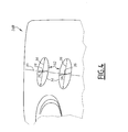
figure 6 est une représentation schématique des phases de l'étape de lafigure 5 .
- the
figure 1 is a schematic representation of a defect characterization system implemented by the method according to the invention; - the
figure 2 is an operating flow diagram of the method according to the invention; - the
figure 3 is an image of an area to be analyzed by the method according to the invention; - the
figure 4 is an image used for the calibration of the system according to the invention; - the
figure 5 is an operating flow chart of the method according to the invention, during the step of defining a succession of measurement points; and - the
figure 6 is a schematic representation of the phases of the stage of thefigure 5 .
Sur la
La source lumineuse 12 comporte un réglage du niveau de luminosité. La source lumineuse 12 est montée sur un support 22 muni de moyens de réglage de la position et de la direction de la source lumineuse.The
L'écran réfléchissant 14 est destiné à renvoyer un faisceau lumineux, issu de la source lumineuse 12 et réfléchi par la pièce 19, à nouveau sur la pièce 19.The reflecting
Le dispositif 16 de capture d'images est une caméra numérique.The
L'unité 18 de traitement comporte des moyens de contrôle de la caméra 16 et de la table 20, et un dispositif de traitement d'images.The
Le procédé est mis en oeuvre sous la commande d'un programme d'ordinateur contenu dans l'unité 18 de traitement d'informations.The method is implemented under the control of a computer program contained in the
Comme représenté sur la
Un défaut 23 correspond à un relief abrupte et indésirable de la surface de la pièce 19. Une coupe selon un plan transversal de la pièce 19 passant par le défaut 23 se caractérise par au moins trois changements de pente. Un premier changement de pente correspond à une extrémité d'une coupe du défaut 23 selon le plan transversal, un deuxième changement de pente correspond à un point de relief maximal de ladite coupe du défaut 23 et un troisième changement de pente correspond à l'autre extrémité de ladite coupe du défaut 23. Lorsque le relief présente une ondulation, le nombre de changements de pente est supérieur à 3, le premier et le dernier changement de pente correspondant aux deux extrémités de ladite coupe du défaut 23.A
A l'étape 100, une image 24A de la zone à analyser de la pièce 19 est capturée par la caméra 16 et enregistrée par l'unité de traitement 18. L'image 24A, visible partiellement sur la
Le niveau de gris représente l'intensité lumineuse d'un pixel. Dans le mode de réalisation décrit, des zones en forme de bosse, représentées par des zones claires sur l'image 24A, réfléchissent plus le faisceau de lumière de la source lumineuse 12 que des zones en forme de creux, représentées par des zones sombres sur l'image 24A.The gray level represents the luminous intensity of a pixel. In the embodiment described, hump-like areas, represented by light areas in the
A l'étape 110, le système 10 est calibré à l'aide d'une image 24B de calibrage, visible sur la
A l'étape 120, deux points de mesures positionnés de part et d'autre du défaut 23 sont sélectionnés par l'opérateur, ce qui détermine le point de mesure initial 25. Une succession de points de mesure 26 suivant la longueur d'un défaut 23, visible sur les
L'étape 120 est destinée à déterminer et à quantifier les changements de pente pour chaque coupe transversale de la pièce 19 passant par le défaut 23. Les coupes transversales sont déterminées en se déplaçant le long du défaut 23 à partir d'une première coupe transversale, choisie par un opérateur.Step 120 is intended to determine and quantify slope changes for each cross section of
Une portion d'une coupe transversale de la pièce 19 correspond à un segment défini sur l'image 24A en niveau de gris. Un profil est calculé à partir de ce segment. Chaque pixel du profil d'abscisse X et d'ordonnée Y est égal à la variation en niveau de gris en le pixel d'abscisse X et d'ordonnée Y dudit segment selon la longueur et la direction dudit segment. Chaque pixel du profil correspond à la pente en un point de la portion de ladite coupe transversale de la pièce 19 passant par le défaut 23.A portion of a cross section of the
La variation de niveau de gris en un pixel dudit profil suivant la longueur et la direction de ce profil correspond à la variation de la pente en un point de la portion de ladite coupe transversale passant par le défaut 23. Les changements de pente recherchés dans ladite portion correspondent alors à une variation extrémale de niveau de gris en un pixel dudit profil.The variation of gray level in a pixel of said profile along the length and the direction of this profile corresponds to the variation of the slope at a point of the portion of said cross section passing through the
Le critère prédéfini de l'étape 120 consiste à rechercher le pixel, où la variation de niveaux de gris suivant la longueur et la direction d'un profil donné est extrémale. Une succession de profils est déterminée en se déplaçant le long du défaut 23 en fonction de ce critère, à partir d'un premier profil choisi par l'opérateur.The predefined criterion of
A l'étape 130, une caractérisation du défaut 23 de la pièce est déduite à partir de l'ensemble des paramètres géométriques enregistrés aux différents points de mesure 25, 26. Un indice de qualité est attribué à la pièce 19 en fonction de la caractérisation du défaut 23.In
Lors de l'étape 110 de calibrage, représentée sur la
L'étape 110 de calibrage consiste à localiser deux gabarits 32 en forme de cercle de diamètre réel connu sur la pièce 19. Les deux gabarits 32 sont déposés sur la pièce 19 au voisinage du défaut 23. Le premier des deux gabarits 32 est placé en zone avant et le second en zone arrière, recouvrant ainsi la totalité du champ de l'image. Les deux gabarits 32 doivent apparaître en totalité sur l'image 24B, afin d'appréhender le centre des deux cercles. L'unité 18 calcule automatiquement le bord 34 des cercles en utilisant des opérations morphologiques sur l'image 24B. Les opérations morphologiques sont une expansion et une érosion pour extraire les bords 34, puis un filtre Sobel pour éliminer le bruit. Le système 10 identifie ensuite pour chaque cercle 32, un diamètre 36 suivant une direction donnée et son centre 38. Les bords 34 et les centres 38 des cercles sont enregistrés par l'unité de traitement 18.The
La direction 30, dans laquelle la relation de correspondance entre un pixel et sa taille réelle est calculée, est la droite reliant deux centres 38 de cercles. La relation de correspondance, ou relation de proportionnalité, est déterminée pour la distance entre les centres 38, afin de prendre en compte le paramètre de la profondeur de champ des images 24A et 24B, prises dans les mêmes conditions opératoires.The direction 30, in which the correspondence relation between a pixel and its real size is calculated, is the straight line connecting two
La relation de correspondance est, par exemple, exprimée sous la forme d'un rapport α de la distance réelle connue entre les centres 38 sur le nombre de pixels entre les centres 38, selon la direction 30. L'unité de mesure pour les distances réelles sur la pièce 19 est le millimètre. Chaque pixel d'un segment selon la direction 30 a alors une taille réelle égale à α millimètres.The correspondence relation is, for example, expressed in the form of a ratio α of the known actual distance between the
L'étape 120 de calcul des paramètres géométriques du défaut est illustrée sur la
Lors de la phase initiale 200, l'opérateur détermine un premier profil de mesure 40 en choisissant ses deux extrémités 42 dans une portion de l'image 24A, où le défaut 23 est visible. Le premier profil 40 est déterminé autant que possible dans une direction sensiblement perpendiculaire au défaut 23.During the
Un algorithme de détermination de la variation extrémale de niveaux de gris est ensuite appliqué au profil de mesure initial 40, afin de calculer le point de mesure initial 25.An algorithm for determining the extreme variation of gray levels is then applied to the
L'algorithme de détermination de la variation extrémale de niveaux de gris met en oeuvre successivement deux filtres et s'applique à un profil donné.The algorithm for determining the extreme variation of gray levels successively implements two filters and applies to a given profile.
Le premier filtre est une moyenne de niveaux de gris de pixels adjacents suivant une direction sensiblement perpendiculaire au profil 40, 44, 46 sélectionné.The first filter is an average of gray levels of adjacent pixels in a direction substantially perpendicular to the
Lors de l'application du premier filtre, le procédé sélectionne une portion 47 de l'image 24A, contenant le profil 40, 44, 46 sélectionné. La portion 47 est en forme d'un rectangle, dont les bords sont parallèles au bord de l'image 24A. La portion 47 est représentée de manière mathématique par une matrice I, dont chaque élément est la valeur en niveaux de gris d'un pixel. Les éléments de la matrice I sont rangés en fonction de l'abscisse X et de l'ordonnée Y de chaque pixel.When the first filter is applied, the method selects a
L'unité 18 de traitement effectue ensuite une rotation de la portion 47 d'un angle Θ, de sorte que le profil 40, 44, 46 sélectionné est, après rotation de la portion 47, parallèle à l'axe des ordonnées de l'image 24A. La rotation d'angle Θ est effectuée en multipliant la matrice I par une matrice de rotation d'angle Θ pour obtenir une matrice Ir. La matrice Ir est la représentation mathématique de la portion 47 après rotation d'angle Θ.The
Une moyenne est enfin effectuée sensiblement perpendiculairement au profil 40, 44, 46 sélectionné pour un nombre M de pixels. M est, par exemple, compris entre 5 et 10.An average is finally made substantially perpendicular to the
Le résultat obtenu est une matrice Im, dont les éléments sont calculés en fonction des éléments de la matrice Ir selon la formule suivante : 
où Im(x,y) est l'élément de la matrice Im, exprimé en niveau de gris, correspondant au pixel d'abscisse X et d'ordonnée Y et Ir(X,Y) est l'élément de la matrice Ir, exprimé en niveau de gris, correspondant au pixel d'abscisse X et d'ordonnée Y.The result obtained is a matrix Im, whose elements are calculated according to the elements of the matrix Ir according to the following formula:
where Im (x, y) is the element of the matrix Im, expressed in gray level, corresponding to the abscissa pixel X and ordinate Y and Ir (X, Y) is the element of the matrix Ir, expressed in gray level, corresponding to the abscissa pixel X and the ordinate Y.
Le deuxième filtre mis en oeuvre dans l'algorithme de détermination de la variation extrémale de niveaux de gris est un filtre de lissage, afin de diminuer le bruit dans le profil moyenné. Le filtre de lissage est, par exemple, un filtre ondulatoire de lissage basé sur une variante heuristique du principe de Steind. Le filtre de lissage se décompose en deux étapes successives.The second filter implemented in the algorithm for determining the extreme variation of gray levels is a smoothing filter, in order to reduce the noise in the averaged profile. The smoothing filter is, for example, a wave smoothing filter based on a heuristic variant of the Steind principle. The smoothing filter is broken down into two successive steps.
Lors de la première étape, le filtre analyse tous les pixels du profil moyenné afin d'évaluer les pixels de début et de fin du profil moyenné. Lors de la deuxième étape, le signal issu de la première étape est à nouveau filtré en considérant les informations entres les pixels de début et de fin, de sorte que le signal filtré à l'issue de la deuxième étape est indépendant de la longueur du profil moyenné.In the first step, the filter analyzes all the pixels of the averaged profile to evaluate the start and end pixels of the averaged profile. In the second step, the signal from the first step is again filtered by considering the information between the start and end pixels, so that the signal filtered at the end of the second step is independent of the length of the averaged profile.
Dans la suite de la phase 200, l'unité 18 de traitement centre le profil de mesure initial 40 sur le point de mesure initial 25. Une variable G est fixée à la valeur 1, afin d'indiquer que l'unité 18 va dans un premier temps rechercher les points de mesure 26 dans la partie de l'image 24A située à gauche du profil de mesure initial 40. L'unité 18 passe ensuite à la phase 210.In the continuation of the
Lors de la phase 210, un profil intermédiaire 44 est déterminé par translation du profil de mesure initial 40 d'un nombre N de pixels selon une direction orthogonale à la direction du profil de mesure initial 40. Si la variable G est égale à 1, alors la translation est effectuée vers la gauche. Si la variable G est égale à 0, alors la translation est effectuée vers la droite. N est de préférence compris entre 1 et 10 et par exemple égal à 5. L'unité 18 de traitement passe alors à la phase 215.During the
La phase 215 est une phase de calcul du point de mesure 26 suivant. La phase 215 comprend la définition d'un pixel intermédiaire 45 pour lequel la variation de niveaux de gris suivant la longueur et la direction du profil intermédiaire 44 est extrémale et le repositionnement sur le défaut 23 en un point de mesure suivant 26 à partir du pixel intermédiaire 45. La phase 215 comporte plusieurs stades successifs 220 à 270.
Au stade 220, la valeur de la variation extrémale de niveaux de gris du profil intermédiaire 44 et les coordonnées du pixel intermédiaire 45 pour lequel la variation de niveaux de gris suivant la longueur et la direction du profil intermédiaire 44 est extrémale, sont déterminés à l'aide de l'algorithme de détermination de la variation extrémale de niveaux de gris. L'unité 18 passe alors du stade 220 au stade 230.In
Au stade 230, l'unité 18 de traitement effectue une rotation autour du pixel intermédiaire 45 dans une plage de +/- R degrés et détermine la direction dans laquelle la variation de niveaux de gris est extrémale au pixel intermédiaire 45. Le balayage est effectué par pas d'un degré, à partir de l'angle -R degrés. R est de préférence compris entre 1 et 20, et par exemple égal à 10. L'angle 0° correspond à la direction du profil intermédiaire 44. L'angle de rotation entre la direction du profil intermédiaire 44 et la direction, dans laquelle la variation de niveaux de gris est extrémale, est appelé Rgrad. L'unité 18 passe alors du stade 230 au stade 240.In
Au stade 240, un profil intermédiaire 44 suivant est déterminé par rotation de l'angle Rgrad du profil intermédiaire 44 précédent, afin d'être orienté selon la direction de variation extrémale de niveaux de gris. L'unité 18 passe du stade 240 au stade 250.At
Au stade 250, l'unité 18 de traitement teste si une condition d'arrêt prédéterminée est remplie et dans ce cas passe au stade 260. Lorsque la condition d'arrêt prédéterminée est remplie, l'algorithme a convergé vers un profil de mesure 46 suivant, correspondant au dernier profil intermédiaire 44 calculé.At
Le profil de mesure 46 suivant est alors sensiblement perpendiculaire au défaut 23 en son point de mesure 26, de par les différentes rotations successives des profils intermédiaires 44, chacune étant effectuée vers une direction de variation extrémale de niveaux de gris.The
Si la condition d'arrêt prédéterminée n'est pas remplie, alors l'unité 18 retourne au stade 220.If the predetermined stopping condition is not met, then
La condition d'arrêt prédéterminée comprend la condition que la variation extrémale de niveaux de gris et la direction dans laquelle la variation de niveaux de gris est extrémale sont sensiblement identiques respectivement à la variation extrémale de niveaux de gris précédente et à la direction précédente de variation extrémale de niveaux de gris.The predetermined stopping condition includes the condition that the extremal variation of gray levels and the direction in which the variation of gray levels is extremal are substantially identical respectively to the preceding variation of gray levels of gray and to the previous direction of variation. extremal levels of gray.
Au stade 260, l'unité 18 de traitement teste si le nombre d'itérations sans évolution de la variation extrémale de niveaux de gris et de la direction dans laquelle la variation de niveaux de gris est extrémale est égal à Imax. Imax est par exemple égal à 3. Si cette condition est vérifiée, alors l'unité 18 passe au stade 270. Sinon, les paramètres géométriques correspondant à la dernière itération sont enregistrés et l'unité 18 passe au stade 280.In
Au stade 270, les paramètres géométriques correspondant à la première des trois itérations identiques sont enregistrés et l'unité 18 passe ensuite au stade 280.At
Au stade 280, l'unité 18 de traitement teste si une condition parmi les conditions de fin du défaut 23 est remplie et dans ce cas passe à une phase 290. Si aucune condition parmi les conditions de fin du défaut 23 n'est remplie, alors le procédé retourne à la phase 210, où un nouveau profil intermédiaire 44 est déterminé par translation de N pixels à partir du dernier profil de mesure 46.In
Une première condition des conditions de fin du défaut 23 est que la variation extrémale de niveaux de gris du profil de mesure 46 suivant est inférieure à une valeur prédéterminée. La valeur prédéterminée est, par exemple, comprise entre 3 et 5 unités de variation de gris par pixel.A first condition of the conditions of end of the
Une deuxième condition des conditions de fin du défaut 23 est que l'algorithme de progression le long du défaut est dans une zone de l'image 24A, où la valeur moyenne en niveau de gris des pixels de ladite zone est supérieure à une valeur de seuil maximal. La valeur de seuil maximal est, par exemple, égale à 200.A second condition of the end conditions of the
Une troisième condition des conditions de fin du défaut 23 est que l'algorithme est dans une zone de l'image 24A, où la valeur moyenne en niveau de gris des pixels de ladite zone est inférieure à une valeur de seuil minimal. La valeur de seuil minimal est, par exemple, égale à 50.A third condition of the end conditions of the
Lors de la phase 290, l'unité 18 de traitement vérifie si le calcul des paramètres géométriques a déjà été effectué par translations successives vers la droite à partir du profil de mesure initial 40. En d'autres termes, l'unité 18 teste si la variable G est égale à 0 et dans ce cas passe à l'étape 130 de caractérisation du défaut. Si la variable G est égale à 1, alors l'unité 18 passe à la phase 300.During the
Lors de la phase 300, l'algorithme de progression le long du défaut se repositionne sur le profil de mesure initial 40 au point de mesure initial 25. La variable G est fixée à 0, de sorte que les translations effectuées lors de la phase 210 seront dirigées vers la droite, et non plus vers la gauche. L'unité 18 retourne ensuite à la phase 210.During
Lors de l'étape 130 de caractérisation du défaut, l'unité 18 de traitement réalise la jonction de chaque point de mesure 25, 26, pour obtenir une ligne 48 du défaut. Cette jonction est, par exemple, effectuée en partant du dernier point de mesure 26 calculé et en le reliant au point de mesure 25, 26 le plus proche géographiquement dans l'image 24A, et ainsi de suite.During the
Les paramètres du défaut sont calculés à partir des paramètres géométriques déterminés à l'étape 120 pour chaque point de mesure 25, 26.The fault parameters are calculated from the geometrical parameters determined in
Un premier paramètre du défaut 23 est la longueur développée de la ligne 48 du défaut, également appelée longueur du défaut 23.A first parameter of the
Un deuxième paramètre du défaut 23 est la plus grande longueur de profil parmi les différents profils de mesure 40, 46 calculés. La plus grande longueur de profil 40, 46 est également appelée largeur du défaut 23.A second parameter of the
Un troisième paramètre du défaut 23 est la valeur extrémale parmi les différentes variations extrémales de niveaux de gris calculées, également appelée changement maximal de pente du défaut 23.A third parameter of the
Un quatrième paramètre du défaut 23 est la direction correspondant à la valeur extrémale parmi les différentes variations extrémales de niveaux de gris calculées, qui représente la direction dans laquelle le défaut 23 est le plus visible.A fourth parameter of the
Un cinquième paramètre du défaut 23 est l'aire d'un secteur 50 situé à l'intérieur d'un contour 52. Le contour 52 est la courbe qui relie les extrémités des différents profils de mesure 40, 46. L'aire du secteur 50 est également appelée surface du défaut 23.A fifth parameter of the
L'unité 18 de traitement déduit la caractérisation du défaut de la pièce 19 à partir des premier, deuxième et troisième paramètres du défaut 23, à savoir la longueur du défaut 23, la largeur du défaut 23 et le changement maximal de pente du défaut 23. Pour chaque paramètre de caractérisation, plusieurs valeurs qualitatives sont possibles telles que petit, moyen et grand. La relation entre la valeur qualitative et la valeur mathématique pour chaque paramètre de caractérisation est prédéterminée selon des critères de qualité. L'unité 18 détermine alors un indice de qualité globale de la pièce 19 en fonction des valeurs qualitatives de chaque paramètre de caractérisation.The
A l'issue de l'étape 130, l'unité 18 enregistre et affiche l'indice de qualité de la pièce 19 pour consultation par l'opérateur.At the end of
Ainsi, le procédé de caractérisation des défauts 23 met en oeuvre des algorithmes relativement simples et nécessite un temps de calcul réduit. Il permet de caractériser des défauts 23 de faible amplitude, de l'ordre de 10 à 200 micromètres, pour des zones de la pièce 19 ayant une aire relativement importante.Thus, the
Claims (13)
Applications Claiming Priority (1)
| Application Number | Priority Date | Filing Date | Title |
|---|---|---|---|
| FR0852390A FR2930032B1 (en) | 2008-04-09 | 2008-04-09 | METHOD AND INSTALLATION FOR CHARACTERIZING A SURFACE DEFECT ON A WORKPIECE |
Publications (1)
| Publication Number | Publication Date |
|---|---|
| EP2109079A1 true EP2109079A1 (en) | 2009-10-14 |
Family
ID=40257342
Family Applications (1)
| Application Number | Title | Priority Date | Filing Date |
|---|---|---|---|
| EP09155411A Withdrawn EP2109079A1 (en) | 2008-04-09 | 2009-03-17 | Method and system of characterisation of a surface defect of a workpiece |
Country Status (2)
| Country | Link |
|---|---|
| EP (1) | EP2109079A1 (en) |
| FR (1) | FR2930032B1 (en) |
Cited By (10)
| Publication number | Priority date | Publication date | Assignee | Title |
|---|---|---|---|---|
| CN110544238A (en) * | 2019-08-12 | 2019-12-06 | 华南理工大学 | Flexible circuit board line defect identification method based on geometric positioning |
| CN111476779A (en) * | 2020-04-07 | 2020-07-31 | 国家林业和草原局北京林业机械研究所 | Sawn timber surface defect position positioning method and system |
| CN111612769A (en) * | 2020-05-22 | 2020-09-01 | 湘潭市锦程半导体科技有限公司 | Method for detecting surface concave-convex defect of triode packaging metal cap |
| CN111967088A (en) * | 2020-07-31 | 2020-11-20 | 中国第一汽车股份有限公司 | Reverse curved surface design method for inner plate beam type part |
| CN112710250A (en) * | 2020-11-23 | 2021-04-27 | 武汉光谷卓越科技股份有限公司 | Three-dimensional measurement method based on line structured light and sensor |
| CN113686897A (en) * | 2021-08-05 | 2021-11-23 | 江苏维普光电科技有限公司 | Mask surface particle defect detection method |
| CN114061524A (en) * | 2021-10-15 | 2022-02-18 | 首钢集团有限公司 | Steel coil profile measuring method and device |
| CN115575402A (en) * | 2022-10-17 | 2023-01-06 | 中国兵器装备集团西南技术工程研究所 | Intelligent identification, calculation and judgment method for defects of inner wall of closed cylindrical part |
| CN116758067A (en) * | 2023-08-16 | 2023-09-15 | 梁山县成浩型钢有限公司 | Metal structural member detection method based on feature matching |
| CN117078667A (en) * | 2023-10-13 | 2023-11-17 | 山东克莱蒙特新材料科技有限公司 | Mineral casting detection method based on machine vision |
Citations (3)
| Publication number | Priority date | Publication date | Assignee | Title |
|---|---|---|---|---|
| US4920385A (en) | 1984-02-14 | 1990-04-24 | Diffracto Ltd. | Panel surface flaw inspection |
| WO1993012615A1 (en) * | 1991-12-19 | 1993-06-24 | The United States Of America, Represented By The Secretary, United States Department Of Commerce | Method and apparatus for assessment of surface smoothness using reflected energy |
| US6038335A (en) * | 1995-06-05 | 2000-03-14 | Matsushita Electric Industrial Co. Ltd. | Flaw detection apparatus using digital image data indicative of a surface of an object |
-
2008
- 2008-04-09 FR FR0852390A patent/FR2930032B1/en not_active Expired - Fee Related
-
2009
- 2009-03-17 EP EP09155411A patent/EP2109079A1/en not_active Withdrawn
Patent Citations (3)
| Publication number | Priority date | Publication date | Assignee | Title |
|---|---|---|---|---|
| US4920385A (en) | 1984-02-14 | 1990-04-24 | Diffracto Ltd. | Panel surface flaw inspection |
| WO1993012615A1 (en) * | 1991-12-19 | 1993-06-24 | The United States Of America, Represented By The Secretary, United States Department Of Commerce | Method and apparatus for assessment of surface smoothness using reflected energy |
| US6038335A (en) * | 1995-06-05 | 2000-03-14 | Matsushita Electric Industrial Co. Ltd. | Flaw detection apparatus using digital image data indicative of a surface of an object |
Non-Patent Citations (5)
| Title |
|---|
| FRIEDRICH M. WAHL: "Digitale Bildsignalverarbeitung : chapitre: 5.2.4 : Konturverfolgung", SPRINGER, BERLIN, 1984, XP002511749 * |
| ONDULO: "une nouvelle approche du défaut d'aspect de surface par la courbure", JOURNAL SURFACES, 2002, pages 51 - 53 |
| STEVEN D ET AL., PROCEEDINGS OF CMSC 2005, July 2005 (2005-07-01) |
| ZAMPERONI P: "Contour tracing of grey-scale images based on 2-D histograms", PATTERN RECOGNITION UK, vol. 15, no. 3, 1982, pages 161 - 165, XP002511750, ISSN: 0031-3203 * |
| ZHAO YU-MING; ZHANG GUO-ZHONG; YU ZHE-FENG: "Point cloud fitting of NURBS curved surface in reverse design of automobiles", NATURAL SENSE, vol. 26, no. 7, July 2005 (2005-07-01), pages 680 - 2 |
Cited By (15)
| Publication number | Priority date | Publication date | Assignee | Title |
|---|---|---|---|---|
| CN110544238B (en) * | 2019-08-12 | 2023-01-06 | 华南理工大学 | Flexible circuit board line defect identification method based on geometric positioning |
| CN110544238A (en) * | 2019-08-12 | 2019-12-06 | 华南理工大学 | Flexible circuit board line defect identification method based on geometric positioning |
| CN111476779A (en) * | 2020-04-07 | 2020-07-31 | 国家林业和草原局北京林业机械研究所 | Sawn timber surface defect position positioning method and system |
| CN111476779B (en) * | 2020-04-07 | 2023-09-12 | 中国林业科学研究院木材工业研究所 | Sawn timber surface defect position positioning method and sawn timber surface defect position positioning system |
| CN111612769A (en) * | 2020-05-22 | 2020-09-01 | 湘潭市锦程半导体科技有限公司 | Method for detecting surface concave-convex defect of triode packaging metal cap |
| CN111967088A (en) * | 2020-07-31 | 2020-11-20 | 中国第一汽车股份有限公司 | Reverse curved surface design method for inner plate beam type part |
| CN112710250A (en) * | 2020-11-23 | 2021-04-27 | 武汉光谷卓越科技股份有限公司 | Three-dimensional measurement method based on line structured light and sensor |
| CN113686897A (en) * | 2021-08-05 | 2021-11-23 | 江苏维普光电科技有限公司 | Mask surface particle defect detection method |
| CN113686897B (en) * | 2021-08-05 | 2023-11-03 | 江苏维普光电科技有限公司 | Mask surface particle defect detection method |
| CN114061524A (en) * | 2021-10-15 | 2022-02-18 | 首钢集团有限公司 | Steel coil profile measuring method and device |
| CN115575402A (en) * | 2022-10-17 | 2023-01-06 | 中国兵器装备集团西南技术工程研究所 | Intelligent identification, calculation and judgment method for defects of inner wall of closed cylindrical part |
| CN116758067A (en) * | 2023-08-16 | 2023-09-15 | 梁山县成浩型钢有限公司 | Metal structural member detection method based on feature matching |
| CN116758067B (en) * | 2023-08-16 | 2023-12-01 | 梁山县成浩型钢有限公司 | Metal structural member detection method based on feature matching |
| CN117078667A (en) * | 2023-10-13 | 2023-11-17 | 山东克莱蒙特新材料科技有限公司 | Mineral casting detection method based on machine vision |
| CN117078667B (en) * | 2023-10-13 | 2024-01-09 | 山东克莱蒙特新材料科技有限公司 | Mineral casting detection method based on machine vision |
Also Published As
| Publication number | Publication date |
|---|---|
| FR2930032A1 (en) | 2009-10-16 |
| FR2930032B1 (en) | 2010-05-14 |
Similar Documents
| Publication | Publication Date | Title |
|---|---|---|
| EP2109079A1 (en) | Method and system of characterisation of a surface defect of a workpiece | |
| EP2491375A1 (en) | Method for analysing the quality of a glass panel | |
| FR2756626A1 (en) | SYSTEM FOR MEASURING GAMES AND FLOORS BETWEEN OPPOSITE PARTS | |
| FR3025918A1 (en) | METHOD AND SYSTEM FOR AUTOMATED MODELING OF A PART | |
| US10379006B2 (en) | Data generation method and data generation apparatus | |
| CA2066117A1 (en) | Method of dimensional control of moving articles | |
| FR3076619A1 (en) | METHOD, DEVICE AND INSPECTION LINE FOR DETERMINING THREE DIMENSIONAL GEOMETRY OF A CONTAINER RING SURFACE | |
| CA2880145A1 (en) | Method for the non-destructive testing of a blade preform | |
| EP2208963B1 (en) | Method for measuring gaps and flushes | |
| CA1313712C (en) | Length measuring method using a photosensitive arroy camera | |
| WO2001025744A1 (en) | Method and apparatus for centring an ophthalmic lens | |
| EP1921442A1 (en) | Method and installation for controlling the quality of parts | |
| EP0559594B1 (en) | Process for creating the signature of an object represented on a digital image, from the type consisting in defining at least one caracteristic dimensional calibre of that object and corresponding process for verifying the signature of an object | |
| EP3304038B1 (en) | Device with a single camera and measuring method for characterising rain drops | |
| EP3080592A1 (en) | Method and device for analyzing the surface of a substrate | |
| WO2014053740A1 (en) | Method of determination of a characterized zone of a glazing | |
| EP1528409B1 (en) | Method and system for measuring the speed of a vehicle on a curved trajectory | |
| EP2904543B1 (en) | Method for counting persons for a stereoscopic devicee and corresponding stereoscopic device for counting persons | |
| EP3903282B1 (en) | Method for segmenting an image | |
| FR2974414A1 (en) | METHOD FOR ANALYZING THE QUALITY OF A GLAZING | |
| EP0689048B1 (en) | Method for the obtention of the image of an object rotating around an axis by means of tangential radiography | |
| WO2024056955A1 (en) | Device and method for checking the flatness of a metal sheet | |
| WO2021099395A1 (en) | Method for detecting intensity peaks of a specularly reflected light beam | |
| FR3140159A1 (en) | Method for adjusting a magnetic sensor | |
| FR3116902A1 (en) | METHOD FOR DETECTING POSSIBLE DENTS ON A SURFACE CAPABLE OF REFLECTING LIGHT |
Legal Events
| Date | Code | Title | Description |
|---|---|---|---|
| PUAI | Public reference made under article 153(3) epc to a published international application that has entered the european phase |
Free format text: ORIGINAL CODE: 0009012 |
|
| AK | Designated contracting states |
Kind code of ref document: A1 Designated state(s): AT BE BG CH CY CZ DE DK EE ES FI FR GB GR HR HU IE IS IT LI LT LU LV MC MK MT NL NO PL PT RO SE SI SK TR |
|
| AX | Request for extension of the european patent |
Extension state: AL BA RS |
|
| 17P | Request for examination filed |
Effective date: 20100330 |
|
| 17Q | First examination report despatched |
Effective date: 20100506 |
|
| AKX | Designation fees paid |
Designated state(s): DE ES FR GB IT |
|
| RAP1 | Party data changed (applicant data changed or rights of an application transferred) |
Owner name: GM GLOBAL TECHNOLOGY OPERATIONS LLC Owner name: PEUGEOT CITROEN AUTOMOBILES SA |
|
| RAP1 | Party data changed (applicant data changed or rights of an application transferred) |
Owner name: PEUGEOT CITROEN AUTOMOBILES SA |
|
| STAA | Information on the status of an ep patent application or granted ep patent |
Free format text: STATUS: THE APPLICATION IS DEEMED TO BE WITHDRAWN |
|
| 18D | Application deemed to be withdrawn |
Effective date: 20151001 |