EP2208864B1 - Inlet bleed heat system for thermal lag mitigation using compressor interstage bleeds - Google Patents
Inlet bleed heat system for thermal lag mitigation using compressor interstage bleeds Download PDFInfo
- Publication number
- EP2208864B1 EP2208864B1 EP10150526.1A EP10150526A EP2208864B1 EP 2208864 B1 EP2208864 B1 EP 2208864B1 EP 10150526 A EP10150526 A EP 10150526A EP 2208864 B1 EP2208864 B1 EP 2208864B1
- Authority
- EP
- European Patent Office
- Prior art keywords
- compressor
- inlet
- housing
- air supply
- air
- Prior art date
- Legal status (The legal status is an assumption and is not a legal conclusion. Google has not performed a legal analysis and makes no representation as to the accuracy of the status listed.)
- Active
Links
- 230000000116 mitigating effect Effects 0.000 title claims description 5
- 238000010792 warming Methods 0.000 claims description 15
- 230000004913 activation Effects 0.000 claims description 9
- 238000011144 upstream manufacturing Methods 0.000 claims description 8
- 238000000034 method Methods 0.000 claims description 7
- 230000003213 activating effect Effects 0.000 claims description 4
- 230000000977 initiatory effect Effects 0.000 claims description 3
- 238000013022 venting Methods 0.000 claims 1
- 239000003570 air Substances 0.000 description 54
- 238000001994 activation Methods 0.000 description 7
- XLYOFNOQVPJJNP-UHFFFAOYSA-N water Substances O XLYOFNOQVPJJNP-UHFFFAOYSA-N 0.000 description 5
- 238000002347 injection Methods 0.000 description 4
- 239000007924 injection Substances 0.000 description 4
- 230000001052 transient effect Effects 0.000 description 3
- 239000012080 ambient air Substances 0.000 description 2
- 238000002485 combustion reaction Methods 0.000 description 2
- 238000001816 cooling Methods 0.000 description 2
- 238000000605 extraction Methods 0.000 description 2
- 238000002156 mixing Methods 0.000 description 2
- 238000011084 recovery Methods 0.000 description 2
- 239000007921 spray Substances 0.000 description 2
- 238000004378 air conditioning Methods 0.000 description 1
- 230000004075 alteration Effects 0.000 description 1
- 230000003750 conditioning effect Effects 0.000 description 1
- 238000010276 construction Methods 0.000 description 1
- 238000011217 control strategy Methods 0.000 description 1
- 230000009849 deactivation Effects 0.000 description 1
- 238000010438 heat treatment Methods 0.000 description 1
- 238000002955 isolation Methods 0.000 description 1
- 238000010248 power generation Methods 0.000 description 1
- 238000006467 substitution reaction Methods 0.000 description 1
Images
Classifications
-
- F—MECHANICAL ENGINEERING; LIGHTING; HEATING; WEAPONS; BLASTING
- F01—MACHINES OR ENGINES IN GENERAL; ENGINE PLANTS IN GENERAL; STEAM ENGINES
- F01D—NON-POSITIVE DISPLACEMENT MACHINES OR ENGINES, e.g. STEAM TURBINES
- F01D25/00—Component parts, details, or accessories, not provided for in, or of interest apart from, other groups
- F01D25/08—Cooling; Heating; Heat-insulation
- F01D25/10—Heating, e.g. warming-up before starting
-
- F—MECHANICAL ENGINEERING; LIGHTING; HEATING; WEAPONS; BLASTING
- F02—COMBUSTION ENGINES; HOT-GAS OR COMBUSTION-PRODUCT ENGINE PLANTS
- F02C—GAS-TURBINE PLANTS; AIR INTAKES FOR JET-PROPULSION PLANTS; CONTROLLING FUEL SUPPLY IN AIR-BREATHING JET-PROPULSION PLANTS
- F02C7/00—Features, components parts, details or accessories, not provided for in, or of interest apart form groups F02C1/00 - F02C6/00; Air intakes for jet-propulsion plants
- F02C7/04—Air intakes for gas-turbine plants or jet-propulsion plants
- F02C7/047—Heating to prevent icing
-
- F—MECHANICAL ENGINEERING; LIGHTING; HEATING; WEAPONS; BLASTING
- F02—COMBUSTION ENGINES; HOT-GAS OR COMBUSTION-PRODUCT ENGINE PLANTS
- F02C—GAS-TURBINE PLANTS; AIR INTAKES FOR JET-PROPULSION PLANTS; CONTROLLING FUEL SUPPLY IN AIR-BREATHING JET-PROPULSION PLANTS
- F02C7/00—Features, components parts, details or accessories, not provided for in, or of interest apart form groups F02C1/00 - F02C6/00; Air intakes for jet-propulsion plants
- F02C7/08—Heating air supply before combustion, e.g. by exhaust gases
-
- Y—GENERAL TAGGING OF NEW TECHNOLOGICAL DEVELOPMENTS; GENERAL TAGGING OF CROSS-SECTIONAL TECHNOLOGIES SPANNING OVER SEVERAL SECTIONS OF THE IPC; TECHNICAL SUBJECTS COVERED BY FORMER USPC CROSS-REFERENCE ART COLLECTIONS [XRACs] AND DIGESTS
- Y02—TECHNOLOGIES OR APPLICATIONS FOR MITIGATION OR ADAPTATION AGAINST CLIMATE CHANGE
- Y02T—CLIMATE CHANGE MITIGATION TECHNOLOGIES RELATED TO TRANSPORTATION
- Y02T50/00—Aeronautics or air transport
- Y02T50/60—Efficient propulsion technologies, e.g. for aircraft
Definitions
- aspects of the present invention are directed to thermal lag mitigation in gas turbines using inlet bleed heat (IBH) systems and compressor interstage bleeds.
- IBH inlet bleed heat
- start bleed or interstage bleed air is removed from the compressor to regulate compressor loads during start-up operations and dumped into the gas turbine exhaust downstream of the turbine.
- an IBH system is employed at a late stage of the start-up operations to remove hot air from an aft portion of the compressor and to subsequently deliver the hot air to a filter housing upstream from the compressor for recirculation through the compressor.
- the IBH system includes relatively large quantities of piping, valves, manifolds, etc., all of which are usually metallic.
- piping, valves, manifolds, etc. all of which are usually metallic.
- the IBH system absorbs heat from the compressor flow, the inlet temperature of the compressor air is changing with time.
- the start-up schedule may have to be altered to account for the thermal lag and, thus, control complexity must be increased with turndown capability reduced. Indeed, it has been seen recently, that control strategies have been significantly hampered in having to account for thermal lags in the IBH system.
- JP H10 246 127 A discloses a system to improve power output and thermal efficiency of a gas turbine.
- the system comprises a housing 10 having an inlet for receiving inlet air 6.
- the housing 10 includes louvers 9, a cooling device 35 and an injection nozzle 11 and is fluidly coupled to a compressor 1 of the gas turbine 2.
- the system further comprises feed air means 12 including a first system coupled to an aft portion of the compressor 1 and to the downstream end of the housing 10 via a non-marked and a control valve 14b and a second system coupled to an intermediate portion of the compressor 1 and a pipe conduit arranged between the first and the second control valve and comprising a non-marked cooler.
- the inlet air 6 passes the louvers 9 and is cooled in the cooling device 35 provided in the housing 10.
- the injection nozzle 11 on its upstream side receives compressed cooled air from the feed air means 12 and water from feed water means 13 and on its downstream side forms a water spray flow which is injected in the cooled inlet air flow during passing the injection nozzle 11.
- the drops of the water spray are gasified in the compressor 1 so as to cool the inlet air which is set under pressure in the compressor 1. This improves the power output and the thermal efficiency of the gas turbine.
- the feeding of water to the injection nozzle 11 may be interrupted such that only pressurized air of the first or second system may be injected in the inlet air flow 6.
- GB 1 244 892 A describes an apparatus for controlling the bleed of air from a multistaged compressor 2.
- a duct 12 connects a mid-stage bleed 8 of the compressor to a duct 14 and a duct 16 connects a high-stage bleed 10 of the compressor 1 to the duct 14 which delivers the bleed air to accessories, like an aircraft air-conditioning system or a cabin pressurization system.
- a check valve 18 is disposed in the duct 12 to prevent flow of air from the duct 14 towards the mid-stage bleed 8.
- a normally closed valve 20 is disposed in duct 16.
- the apparatus further comprises pressure sensing 22 means which are arranged either in one of the bleeds 8, 10 or in duct 16 and an actuator 28. This apparatus ensures that at high altitude or low engine revolutions the pressure of the bleed air in the conditioning system and in the cabin of a jet aircraft is sufficient.
- EP 1 375 866 A2 describes an arrangement for heating ambient air.
- the arrangement comprises an inlet duct for receiving the ambient air and directing the air via heater tubes to a compressor of a gas turbine system.
- the heater tubes are part of an inlet bleed heater system which provide the tubes with heated compressed air extracted from a compressor discharge manifold via a line comprising a manual isolation valve and a control valve.
- a system to mitigate thermal lag of start-up operations of a gas turbine comprises a housing which is disposed upstream from and which is fluidly coupled to a compressor of the gas turbine and which comprises an inlet adapted to receive inlet air from the atmosphere, an inlet bleed heat system including piping, valves and manifolds and being coupled to an aft portion of the compressor and to the inlet of the housing which, when activated, receives a first air supply from the compressor and delivers the first air supply to the housing, and an interstage bleed system, coupled to the inlet bleed heat system, which removes a second air supply from an intermediate portion of the compressor, wherein the interstage bleed system is configured to deliver the second air supply to the inlet bleed heat system prior to the activation of the inlet bleed heat system for warming the inlet bleed heat system.
- a method of mitigating thermal lag of start-up operations of a gas turbine including a compressor and a housing disposed upstream from and fluidly coupled to the compressor, includes initiating an operation of the compressor, removing warming air from an intermediate portion of the compressor, delivering the warming air to an inlet bleed heat (IBH) system proximate to a first end thereof, which is coupled to an aft portion of the compressor at the first end and to the housing at a second end thereof, and activating the IBH system to receive a hot air supply from the compressor and to deliver the hot air supply to the housing.
- IBH inlet bleed heat
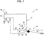
- the gas turbine 20 may have various constructions and configurations but generally includes a compressor 30 in which inlet air is compressed and heated, a combustor 40 downstream from the compressor 30, which receives compressed heated air from the compressor 30 for combustion operations, and a turbine 50 downstream from the combustor 40 in which turbine blades, which are powered by the combustion in the combustor 40, rotate and generate power. Exhaust from the turbine 50 is expelled and directed in many cases to a heat recovery steam generator (HRSG) in which the heat of the exhaust is employed in steam generation and thereby additional power generation.
- HRSG heat recovery steam generator
- the system 10 includes a housing 60, which is disposed upstream from and which is fluidly coupled to the compressor 30.
- a first system 70 is coupled, at a first end 71 thereof, to an extraction point (located at the intersection of the first system 70 and the compressor 30) at an aft portion 33 of the compressor 30 and, at a second end 72 thereof, to the housing 60.
- the first system 70 receives a first air supply, such as a hot air supply, from the compressor 30 and delivers the first air supply to the housing 60.
- a first air supply such as a hot air supply
- a second system 80 is coupled to the first end 71 of the first system 70.
- the second system 80 removes a second air supply, such as a supply of warming air, from an intermediate portion 32 of the compressor 30 and delivers the second air supply to the first system 70 prior to the activation of the first system 70.
- the second air supply is delivered to the first end 71 of the first system 70 proximate to the extraction point of the aft portion 33 of the compressor 30.
- the first system 70 which includes piping, valves, manifolds, etc., is warmed by the warming air of the second air supply.
- the thermal lag resulting from the need for the first system 70 to heat up following its activation is mitigated and relatively warm or hot air may be delivered to the housing 60 by the first system 70 relatively quickly following its activation.
- the first system 70 is generally well insulated, the warmth provided thereto by the warming air is maintained for a relatively long period of time.
- the activation of each of the first and second systems 70 and 80 may be staged in such as way as to substantially reduce a tendency for transient airflow shifts to be created in the compressor 30.
- the housing 60 may include a filter housing or any other suitable housing configuration.
- the housing 60 may further include an inlet 61 to which the second end 72 of the first system 70 is coupled and into which inlet air from the atmosphere enters the gas turbine 10.
- the housing 60 may also include an outlet 62 by which the housing 60 fluidly communicates with an inlet 31 of the compressor 30.
- the first system 70 may include an inlet bleed heat (IBH) system, including relatively large quantities of piping, valves, manifolds, etc., as described above.
- the IBH system may be activated when the gas turbine 10 operates at a preselected percentage of its rated speed, such as about 95% of its rated speed.
- the activation of the IBH system may be conducted at various gas turbine 10 operational speeds in accordance with local and/or current requirements.
- the second system 80 may be configured with multiple branches, such as branches 81 and 82, as shown in FIG. 1 , and removes the second air supply from multiple axial locations 83 and 84 of the intermediate portion 32 of the compressor 30. While the intermediate portion 32 of the compressor 30 may be located at various axial locations of the compressor 30, it is understood that the intermediate portion 32 will generally be forward, along the axis of the compressor 30, from the aft portion 33 of the compressor 30.
- the second system 80 may includes a start or, rather, an interstage bleed system, which is configured to remove the second air supply from the intermediate portion 32 of the compressor 30 so as to regulate a compressor load of the compressor 30.
- the interstage bleed system may operate when the gas turbine 10 operates at 0 to at least a preselected percentage of its rated speed, such as, again, at least about 95% of its rated speed.
- the operation of the interstage bleed system may be conducted at various gas turbine 10 operational speeds in accordance with local and/or current requirements.
- staging of the system activations/deactivations may be configured so as to substantially reduce a tendency for transient airflow shifts to be created in the compressor 30.
- the second air supply may be delivered by first piping 90 to the housing 60, at, e.g., the inlet 61, via the second end 72 of the first system 70.
- the second air supply may be vented by second piping 100 to the atmosphere surrounding the gas turbine 10.
- a method of mitigating thermal lag of start-up operations of a gas turbine 10, including a compressor 30 and a housing 60 disposed upstream from and fluidly coupled to the compressor 30, includes initiating an operation of the compressor 30, removing warming air from an intermediate portion 32 of the compressor 30, delivering the warming air to an inlet bleed heat (IBH) system proximate to a first end 71 thereof, which is coupled to an aft portion 33 of the compressor 30 at the first end 71 and to the housing 60 at a second end 72 thereof, and activating the IBH system to receive a hot air supply from the compressor 30 and to deliver the hot air supply to the housing 60.
- IBH inlet bleed heat
- the warming air may be delivered to the housing 60 or, alternatively, to the atmosphere surrounding the gas turbine 10. Also, the removing of the warming air from the intermediate portion 32 of the compressor 30 and the activating of the IBH system are each conducted when the gas turbine 10 operates at 0 to at least about a preselected percentage of its rated speed.
Landscapes
- Engineering & Computer Science (AREA)
- Chemical & Material Sciences (AREA)
- Combustion & Propulsion (AREA)
- Mechanical Engineering (AREA)
- General Engineering & Computer Science (AREA)
- Control Of Turbines (AREA)
- Structures Of Non-Positive Displacement Pumps (AREA)
- Engine Equipment That Uses Special Cycles (AREA)
Applications Claiming Priority (1)
| Application Number | Priority Date | Filing Date | Title |
|---|---|---|---|
| US12/353,543 US8220275B2 (en) | 2009-01-14 | 2009-01-14 | Inlet bleed heat system thermal lag mitigation using compressor interstage bleeds |
Publications (3)
| Publication Number | Publication Date |
|---|---|
| EP2208864A2 EP2208864A2 (en) | 2010-07-21 |
| EP2208864A3 EP2208864A3 (en) | 2017-06-21 |
| EP2208864B1 true EP2208864B1 (en) | 2019-06-12 |
Family
ID=42174566
Family Applications (1)
| Application Number | Title | Priority Date | Filing Date |
|---|---|---|---|
| EP10150526.1A Active EP2208864B1 (en) | 2009-01-14 | 2010-01-12 | Inlet bleed heat system for thermal lag mitigation using compressor interstage bleeds |
Country Status (4)
| Country | Link |
|---|---|
| US (1) | US8220275B2 (enExample) |
| EP (1) | EP2208864B1 (enExample) |
| JP (1) | JP5268955B2 (enExample) |
| CN (1) | CN101793194B (enExample) |
Families Citing this family (8)
| Publication number | Priority date | Publication date | Assignee | Title |
|---|---|---|---|---|
| US20130219916A1 (en) * | 2012-02-24 | 2013-08-29 | General Electric Company | Apparatus and method for conditioning air received by a power generation system |
| US9027354B2 (en) * | 2012-07-30 | 2015-05-12 | General Elecric Company | System and method for recirculating and recovering energy from compressor discharge bleed air |
| US9719418B2 (en) | 2013-04-01 | 2017-08-01 | General Electric Company | Turbomachine inlet bleed heating assembly |
| US9470150B2 (en) * | 2013-04-30 | 2016-10-18 | General Electric Company | Gas turbine power augmentation system |
| US9963994B2 (en) | 2014-04-08 | 2018-05-08 | General Electric Company | Method and apparatus for clearance control utilizing fuel heating |
| US10036321B2 (en) * | 2014-05-29 | 2018-07-31 | General Electric Company | Systems and methods for utilizing gas turbine compartment ventilation discharge air |
| US10054052B2 (en) * | 2015-07-07 | 2018-08-21 | United Technologies Corporation | Nacelle anti-ice system and method with equalized flow |
| KR101898386B1 (ko) * | 2017-04-24 | 2018-09-12 | 두산중공업 주식회사 | 가스터빈 시스템 및 제어 방법 |
Family Cites Families (15)
| Publication number | Priority date | Publication date | Assignee | Title |
|---|---|---|---|---|
| US2837269A (en) * | 1954-05-03 | 1958-06-03 | United Aircraft Corp | Compressor bleed control |
| US3487993A (en) * | 1968-08-12 | 1970-01-06 | United Aircraft Corp | Compressor bleed air flow control |
| CN85101816A (zh) * | 1985-04-01 | 1987-01-10 | 联合工艺公司 | 有效间隙控制装置 |
| US5473898A (en) * | 1995-02-01 | 1995-12-12 | Westinghouse Electric Corporation | Method and apparatus for warming a steam turbine in a combined cycle power plant |
| US5560195A (en) * | 1995-02-13 | 1996-10-01 | General Electric Co. | Gas turbine inlet heating system using jet blower |
| JP2980095B2 (ja) * | 1995-12-28 | 1999-11-22 | 株式会社日立製作所 | ガスタービン,コンバインドサイクルプラント及び圧縮機 |
| JP2877098B2 (ja) * | 1995-12-28 | 1999-03-31 | 株式会社日立製作所 | ガスタービン,コンバインドサイクルプラント及び圧縮機 |
| US6027304A (en) * | 1998-05-27 | 2000-02-22 | General Electric Co. | High pressure inlet bleed heat system for the compressor of a turbine |
| JP4115037B2 (ja) * | 1999-04-02 | 2008-07-09 | 三菱重工業株式会社 | ガスタービン起動方法 |
| US6685425B2 (en) * | 2002-06-26 | 2004-02-03 | General Electric Company | Inlet bleed heater for heating inlet air to a compressor and methods of fabricating and transporting the heater |
| JP4212322B2 (ja) * | 2002-09-17 | 2009-01-21 | 株式会社Ihi | 燃料電池とマイクロガスタービンのコンバインド発電設備とその起動方法 |
| US7121078B2 (en) * | 2003-01-28 | 2006-10-17 | General Electric Company | Methods and apparatus for operating gas turbine engines |
| US7124591B2 (en) * | 2004-01-09 | 2006-10-24 | Siemens Power Generation, Inc. | Method for operating a gas turbine |
| US7185495B2 (en) * | 2004-09-07 | 2007-03-06 | General Electric Company | System and method for improving thermal efficiency of dry low emissions combustor assemblies |
| US7784288B2 (en) * | 2006-03-06 | 2010-08-31 | General Electric Company | Methods and systems of variable extraction for compressor protection |
-
2009
- 2009-01-14 US US12/353,543 patent/US8220275B2/en not_active Expired - Fee Related
-
2010
- 2010-01-08 JP JP2010002464A patent/JP5268955B2/ja not_active Expired - Fee Related
- 2010-01-12 EP EP10150526.1A patent/EP2208864B1/en active Active
- 2010-01-14 CN CN201010005133.XA patent/CN101793194B/zh not_active Expired - Fee Related
Non-Patent Citations (1)
| Title |
|---|
| None * |
Also Published As
| Publication number | Publication date |
|---|---|
| EP2208864A2 (en) | 2010-07-21 |
| EP2208864A3 (en) | 2017-06-21 |
| US8220275B2 (en) | 2012-07-17 |
| JP5268955B2 (ja) | 2013-08-21 |
| US20100175388A1 (en) | 2010-07-15 |
| JP2010164050A (ja) | 2010-07-29 |
| CN101793194B (zh) | 2015-12-09 |
| CN101793194A (zh) | 2010-08-04 |
Similar Documents
| Publication | Publication Date | Title |
|---|---|---|
| CN110529256B (zh) | 用于燃气涡轮发动机组件的空气循环组件 | |
| US9945247B2 (en) | Gas turbine engine anti-icing system | |
| US10550770B2 (en) | Bleed air systems for use with aircraft and related methods | |
| US7246482B2 (en) | Gas turbine engine bleed air power assist system and method | |
| EP3450722B1 (en) | Air delivery system for a gas turbine engine | |
| US8220275B2 (en) | Inlet bleed heat system thermal lag mitigation using compressor interstage bleeds | |
| EP3002431B1 (en) | Engine bleed air system | |
| US11125165B2 (en) | Thermal management system | |
| US8967528B2 (en) | Bleed air systems for use with aircrafts and related methods | |
| CA2861131C (en) | Method of operating a multi-pack environmental control system | |
| US8261528B2 (en) | System for heating an airstream by recirculating waste heat of a turbomachine | |
| EP2829706B1 (en) | Bleed air systems for use with aircrafts and related methods | |
| EP2009260B1 (en) | Cooling system for use on aircraft | |
| EP3118435B1 (en) | Power augmentation system for a gas turbine using compressed air storage | |
| JP2015511684A (ja) | 制御可能な冷却空気系統を備えたガスタービン | |
| EP3591193B1 (en) | Failure mitigation and failure detection of intercooled cooling air systems of gas turbine engines | |
| CA2499675C (en) | Methods and apparatus for operating gas turbine engines | |
| JP6894197B2 (ja) | ガスタービン用の空気供給及び調和システム | |
| US20220145796A1 (en) | Combustion engine including turbomachine | |
| EP3321490B1 (en) | Turbo-generator based bleed air system | |
| CN106573680A (zh) | 喷气发动机冷空气冷却系统 | |
| JP2025027989A (ja) | ガスタービンシステム用の防氷及び抽気加熱システム | |
| US12269601B2 (en) | Air pressurisation system | |
| EP2589778A2 (en) | System for operating a power plant |
Legal Events
| Date | Code | Title | Description |
|---|---|---|---|
| PUAI | Public reference made under article 153(3) epc to a published international application that has entered the european phase |
Free format text: ORIGINAL CODE: 0009012 |
|
| AK | Designated contracting states |
Kind code of ref document: A2 Designated state(s): AT BE BG CH CY CZ DE DK EE ES FI FR GB GR HR HU IE IS IT LI LT LU LV MC MK MT NL NO PL PT RO SE SI SK SM TR |
|
| AX | Request for extension of the european patent |
Extension state: AL BA RS |
|
| PUAL | Search report despatched |
Free format text: ORIGINAL CODE: 0009013 |
|
| AK | Designated contracting states |
Kind code of ref document: A3 Designated state(s): AT BE BG CH CY CZ DE DK EE ES FI FR GB GR HR HU IE IS IT LI LT LU LV MC MK MT NL NO PL PT RO SE SI SK SM TR |
|
| AX | Request for extension of the european patent |
Extension state: AL BA RS |
|
| RIC1 | Information provided on ipc code assigned before grant |
Ipc: F02C 7/047 20060101ALI20170517BHEP Ipc: F02C 7/08 20060101ALI20170517BHEP Ipc: F01D 25/10 20060101AFI20170517BHEP |
|
| STAA | Information on the status of an ep patent application or granted ep patent |
Free format text: STATUS: REQUEST FOR EXAMINATION WAS MADE |
|
| 17P | Request for examination filed |
Effective date: 20171221 |
|
| RBV | Designated contracting states (corrected) |
Designated state(s): AT BE BG CH CY CZ DE DK EE ES FI FR GB GR HR HU IE IS IT LI LT LU LV MC MK MT NL NO PL PT RO SE SI SK SM TR |
|
| STAA | Information on the status of an ep patent application or granted ep patent |
Free format text: STATUS: EXAMINATION IS IN PROGRESS |
|
| 17Q | First examination report despatched |
Effective date: 20180625 |
|
| GRAP | Despatch of communication of intention to grant a patent |
Free format text: ORIGINAL CODE: EPIDOSNIGR1 |
|
| STAA | Information on the status of an ep patent application or granted ep patent |
Free format text: STATUS: GRANT OF PATENT IS INTENDED |
|
| INTG | Intention to grant announced |
Effective date: 20190226 |
|
| GRAS | Grant fee paid |
Free format text: ORIGINAL CODE: EPIDOSNIGR3 |
|
| GRAA | (expected) grant |
Free format text: ORIGINAL CODE: 0009210 |
|
| STAA | Information on the status of an ep patent application or granted ep patent |
Free format text: STATUS: THE PATENT HAS BEEN GRANTED |
|
| AK | Designated contracting states |
Kind code of ref document: B1 Designated state(s): AT BE BG CH CY CZ DE DK EE ES FI FR GB GR HR HU IE IS IT LI LT LU LV MC MK MT NL NO PL PT RO SE SI SK SM TR |
|
| REG | Reference to a national code |
Ref country code: GB Ref legal event code: FG4D |
|
| REG | Reference to a national code |
Ref country code: CH Ref legal event code: EP |
|
| REG | Reference to a national code |
Ref country code: AT Ref legal event code: REF Ref document number: 1142807 Country of ref document: AT Kind code of ref document: T Effective date: 20190615 |
|
| REG | Reference to a national code |
Ref country code: DE Ref legal event code: R096 Ref document number: 602010059342 Country of ref document: DE |
|
| REG | Reference to a national code |
Ref country code: IE Ref legal event code: FG4D |
|
| REG | Reference to a national code |
Ref country code: NL Ref legal event code: MP Effective date: 20190612 |
|
| REG | Reference to a national code |
Ref country code: LT Ref legal event code: MG4D |
|
| PG25 | Lapsed in a contracting state [announced via postgrant information from national office to epo] |
Ref country code: LT Free format text: LAPSE BECAUSE OF FAILURE TO SUBMIT A TRANSLATION OF THE DESCRIPTION OR TO PAY THE FEE WITHIN THE PRESCRIBED TIME-LIMIT Effective date: 20190612 Ref country code: ES Free format text: LAPSE BECAUSE OF FAILURE TO SUBMIT A TRANSLATION OF THE DESCRIPTION OR TO PAY THE FEE WITHIN THE PRESCRIBED TIME-LIMIT Effective date: 20190612 Ref country code: SE Free format text: LAPSE BECAUSE OF FAILURE TO SUBMIT A TRANSLATION OF THE DESCRIPTION OR TO PAY THE FEE WITHIN THE PRESCRIBED TIME-LIMIT Effective date: 20190612 Ref country code: HR Free format text: LAPSE BECAUSE OF FAILURE TO SUBMIT A TRANSLATION OF THE DESCRIPTION OR TO PAY THE FEE WITHIN THE PRESCRIBED TIME-LIMIT Effective date: 20190612 Ref country code: FI Free format text: LAPSE BECAUSE OF FAILURE TO SUBMIT A TRANSLATION OF THE DESCRIPTION OR TO PAY THE FEE WITHIN THE PRESCRIBED TIME-LIMIT Effective date: 20190612 Ref country code: NO Free format text: LAPSE BECAUSE OF FAILURE TO SUBMIT A TRANSLATION OF THE DESCRIPTION OR TO PAY THE FEE WITHIN THE PRESCRIBED TIME-LIMIT Effective date: 20190912 |
|
| PG25 | Lapsed in a contracting state [announced via postgrant information from national office to epo] |
Ref country code: GR Free format text: LAPSE BECAUSE OF FAILURE TO SUBMIT A TRANSLATION OF THE DESCRIPTION OR TO PAY THE FEE WITHIN THE PRESCRIBED TIME-LIMIT Effective date: 20190913 Ref country code: LV Free format text: LAPSE BECAUSE OF FAILURE TO SUBMIT A TRANSLATION OF THE DESCRIPTION OR TO PAY THE FEE WITHIN THE PRESCRIBED TIME-LIMIT Effective date: 20190612 Ref country code: BG Free format text: LAPSE BECAUSE OF FAILURE TO SUBMIT A TRANSLATION OF THE DESCRIPTION OR TO PAY THE FEE WITHIN THE PRESCRIBED TIME-LIMIT Effective date: 20190912 |
|
| REG | Reference to a national code |
Ref country code: AT Ref legal event code: MK05 Ref document number: 1142807 Country of ref document: AT Kind code of ref document: T Effective date: 20190612 |
|
| PG25 | Lapsed in a contracting state [announced via postgrant information from national office to epo] |
Ref country code: CZ Free format text: LAPSE BECAUSE OF FAILURE TO SUBMIT A TRANSLATION OF THE DESCRIPTION OR TO PAY THE FEE WITHIN THE PRESCRIBED TIME-LIMIT Effective date: 20190612 Ref country code: NL Free format text: LAPSE BECAUSE OF FAILURE TO SUBMIT A TRANSLATION OF THE DESCRIPTION OR TO PAY THE FEE WITHIN THE PRESCRIBED TIME-LIMIT Effective date: 20190612 Ref country code: AT Free format text: LAPSE BECAUSE OF FAILURE TO SUBMIT A TRANSLATION OF THE DESCRIPTION OR TO PAY THE FEE WITHIN THE PRESCRIBED TIME-LIMIT Effective date: 20190612 Ref country code: PT Free format text: LAPSE BECAUSE OF FAILURE TO SUBMIT A TRANSLATION OF THE DESCRIPTION OR TO PAY THE FEE WITHIN THE PRESCRIBED TIME-LIMIT Effective date: 20191014 Ref country code: EE Free format text: LAPSE BECAUSE OF FAILURE TO SUBMIT A TRANSLATION OF THE DESCRIPTION OR TO PAY THE FEE WITHIN THE PRESCRIBED TIME-LIMIT Effective date: 20190612 Ref country code: RO Free format text: LAPSE BECAUSE OF FAILURE TO SUBMIT A TRANSLATION OF THE DESCRIPTION OR TO PAY THE FEE WITHIN THE PRESCRIBED TIME-LIMIT Effective date: 20190612 Ref country code: SK Free format text: LAPSE BECAUSE OF FAILURE TO SUBMIT A TRANSLATION OF THE DESCRIPTION OR TO PAY THE FEE WITHIN THE PRESCRIBED TIME-LIMIT Effective date: 20190612 |
|
| PG25 | Lapsed in a contracting state [announced via postgrant information from national office to epo] |
Ref country code: IS Free format text: LAPSE BECAUSE OF FAILURE TO SUBMIT A TRANSLATION OF THE DESCRIPTION OR TO PAY THE FEE WITHIN THE PRESCRIBED TIME-LIMIT Effective date: 20191012 Ref country code: IT Free format text: LAPSE BECAUSE OF FAILURE TO SUBMIT A TRANSLATION OF THE DESCRIPTION OR TO PAY THE FEE WITHIN THE PRESCRIBED TIME-LIMIT Effective date: 20190612 Ref country code: SM Free format text: LAPSE BECAUSE OF FAILURE TO SUBMIT A TRANSLATION OF THE DESCRIPTION OR TO PAY THE FEE WITHIN THE PRESCRIBED TIME-LIMIT Effective date: 20190612 |
|
| REG | Reference to a national code |
Ref country code: DE Ref legal event code: R097 Ref document number: 602010059342 Country of ref document: DE |
|
| PG25 | Lapsed in a contracting state [announced via postgrant information from national office to epo] |
Ref country code: TR Free format text: LAPSE BECAUSE OF FAILURE TO SUBMIT A TRANSLATION OF THE DESCRIPTION OR TO PAY THE FEE WITHIN THE PRESCRIBED TIME-LIMIT Effective date: 20190612 |
|
| PLBE | No opposition filed within time limit |
Free format text: ORIGINAL CODE: 0009261 |
|
| STAA | Information on the status of an ep patent application or granted ep patent |
Free format text: STATUS: NO OPPOSITION FILED WITHIN TIME LIMIT |
|
| PG25 | Lapsed in a contracting state [announced via postgrant information from national office to epo] |
Ref country code: DK Free format text: LAPSE BECAUSE OF FAILURE TO SUBMIT A TRANSLATION OF THE DESCRIPTION OR TO PAY THE FEE WITHIN THE PRESCRIBED TIME-LIMIT Effective date: 20190612 Ref country code: PL Free format text: LAPSE BECAUSE OF FAILURE TO SUBMIT A TRANSLATION OF THE DESCRIPTION OR TO PAY THE FEE WITHIN THE PRESCRIBED TIME-LIMIT Effective date: 20190612 |
|
| PGFP | Annual fee paid to national office [announced via postgrant information from national office to epo] |
Ref country code: DE Payment date: 20191218 Year of fee payment: 11 |
|
| 26N | No opposition filed |
Effective date: 20200313 |
|
| PG25 | Lapsed in a contracting state [announced via postgrant information from national office to epo] |
Ref country code: SI Free format text: LAPSE BECAUSE OF FAILURE TO SUBMIT A TRANSLATION OF THE DESCRIPTION OR TO PAY THE FEE WITHIN THE PRESCRIBED TIME-LIMIT Effective date: 20190612 Ref country code: IS Free format text: LAPSE BECAUSE OF FAILURE TO SUBMIT A TRANSLATION OF THE DESCRIPTION OR TO PAY THE FEE WITHIN THE PRESCRIBED TIME-LIMIT Effective date: 20200224 |
|
| PG2D | Information on lapse in contracting state deleted |
Ref country code: IS |
|
| PG25 | Lapsed in a contracting state [announced via postgrant information from national office to epo] |
Ref country code: IS Free format text: LAPSE BECAUSE OF FAILURE TO SUBMIT A TRANSLATION OF THE DESCRIPTION OR TO PAY THE FEE WITHIN THE PRESCRIBED TIME-LIMIT Effective date: 20191112 |
|
| PG25 | Lapsed in a contracting state [announced via postgrant information from national office to epo] |
Ref country code: MC Free format text: LAPSE BECAUSE OF FAILURE TO SUBMIT A TRANSLATION OF THE DESCRIPTION OR TO PAY THE FEE WITHIN THE PRESCRIBED TIME-LIMIT Effective date: 20190612 |
|
| REG | Reference to a national code |
Ref country code: CH Ref legal event code: PL |
|
| GBPC | Gb: european patent ceased through non-payment of renewal fee |
Effective date: 20200112 |
|
| REG | Reference to a national code |
Ref country code: BE Ref legal event code: MM Effective date: 20200131 |
|
| PG25 | Lapsed in a contracting state [announced via postgrant information from national office to epo] |
Ref country code: GB Free format text: LAPSE BECAUSE OF NON-PAYMENT OF DUE FEES Effective date: 20200112 Ref country code: FR Free format text: LAPSE BECAUSE OF NON-PAYMENT OF DUE FEES Effective date: 20200131 Ref country code: LU Free format text: LAPSE BECAUSE OF NON-PAYMENT OF DUE FEES Effective date: 20200112 |
|
| PG25 | Lapsed in a contracting state [announced via postgrant information from national office to epo] |
Ref country code: LI Free format text: LAPSE BECAUSE OF NON-PAYMENT OF DUE FEES Effective date: 20200131 Ref country code: BE Free format text: LAPSE BECAUSE OF NON-PAYMENT OF DUE FEES Effective date: 20200131 Ref country code: CH Free format text: LAPSE BECAUSE OF NON-PAYMENT OF DUE FEES Effective date: 20200131 |
|
| PG25 | Lapsed in a contracting state [announced via postgrant information from national office to epo] |
Ref country code: IE Free format text: LAPSE BECAUSE OF NON-PAYMENT OF DUE FEES Effective date: 20200112 |
|
| REG | Reference to a national code |
Ref country code: DE Ref legal event code: R119 Ref document number: 602010059342 Country of ref document: DE |
|
| PG25 | Lapsed in a contracting state [announced via postgrant information from national office to epo] |
Ref country code: DE Free format text: LAPSE BECAUSE OF NON-PAYMENT OF DUE FEES Effective date: 20210803 |
|
| PG25 | Lapsed in a contracting state [announced via postgrant information from national office to epo] |
Ref country code: MT Free format text: LAPSE BECAUSE OF FAILURE TO SUBMIT A TRANSLATION OF THE DESCRIPTION OR TO PAY THE FEE WITHIN THE PRESCRIBED TIME-LIMIT Effective date: 20190612 Ref country code: CY Free format text: LAPSE BECAUSE OF FAILURE TO SUBMIT A TRANSLATION OF THE DESCRIPTION OR TO PAY THE FEE WITHIN THE PRESCRIBED TIME-LIMIT Effective date: 20190612 |
|
| PG25 | Lapsed in a contracting state [announced via postgrant information from national office to epo] |
Ref country code: MK Free format text: LAPSE BECAUSE OF FAILURE TO SUBMIT A TRANSLATION OF THE DESCRIPTION OR TO PAY THE FEE WITHIN THE PRESCRIBED TIME-LIMIT Effective date: 20190612 |