EP2208847A2 - Befestigung eines Abdeckbleches an einem Dachfensterrahmen - Google Patents
Befestigung eines Abdeckbleches an einem Dachfensterrahmen Download PDFInfo
- Publication number
- EP2208847A2 EP2208847A2 EP20100000242 EP10000242A EP2208847A2 EP 2208847 A2 EP2208847 A2 EP 2208847A2 EP 20100000242 EP20100000242 EP 20100000242 EP 10000242 A EP10000242 A EP 10000242A EP 2208847 A2 EP2208847 A2 EP 2208847A2
- Authority
- EP
- European Patent Office
- Prior art keywords
- holding device
- fastening
- pin
- flügelabdeckblech
- roof window
- Prior art date
- Legal status (The legal status is an assumption and is not a legal conclusion. Google has not performed a legal analysis and makes no representation as to the accuracy of the status listed.)
- Granted
Links
Images


Classifications
-
- E—FIXED CONSTRUCTIONS
- E04—BUILDING
- E04D—ROOF COVERINGS; SKY-LIGHTS; GUTTERS; ROOF-WORKING TOOLS
- E04D13/00—Special arrangements or devices in connection with roof coverings; Protection against birds; Roof drainage ; Sky-lights
- E04D13/03—Sky-lights; Domes; Ventilating sky-lights
- E04D13/0305—Supports or connecting means for sky-lights of flat or domed shape
- E04D13/031—Supports or connecting means for sky-lights of flat or domed shape characterised by a frame for connection to an inclined roof
Definitions
- the invention relates to a residential roof window with a sash to which at least one wing cover plate is releasably secured by means of at least one holding device, wherein the holding device is permanently attached to the wellgelabdeckblech by means of at least one fastening device having at least one fastener which passes through a mounting hole of the diegelabdeckblechs and the on the outside of the diegelabdeckblechs projecting end has a rear handle member.
- Roof windows are known from the prior art, in which the holding device is fastened by means of a screw connection to the diegelabdeckblech.
- the attachment is made by riveting.
- at least one rivet or at least one screw, for example two, is provided, which passes through a recess of the holding device and the attachment hole of the diegelabdeckblechs and is fixed there. This may be provided in the case of rivets by the rear engagement element and in the case of the screw by a nut.
- fasteners are always necessary, for example, screws or rivets, which must be introduced during the fastening process in recesses of the holding device and mounting holes of the copelabdeckblechs and secured there.
- the fastening element is designed as a fastening pin integral with the holding device made of plastic and the rear grip element is formed by deformed plastic material of the fastening pin.
- the mounting pin is integrated on the holding device and thereby formed integrally therewith.
- the rear handle member of deformed plastic material protrudes beyond the outside of the rempligelabdeckblechs.
- the deformed plastic material is in particular designed so that there is a good visual impression. This was not possible with the rivets known from the prior art, so that they always had to be arranged with their predesigned rivet head on the outside of the diegelabdeckblechs. The deformed rivet material was thus provided on the holder side.
- the integrally formed with the holding fixture fastening pin eliminates the rivets, so that a metal-free connection is possible.
- the deformation of the plastic material can be made such that on the outside of the rempligelabdeckblechs a perfect visual impression is achieved.
- it can be used colored plastic, the color of the mounting pin so be matched to the material or the color of copelabdeckblechs.
- the deformed plastic material forms the rear grip element, thus holding the mounting pin by rear grip on the rempligelabdeckblech by deformed on the outside of the mounting pin, in particular expanded.
- the mounting pin can be designed as a fastening nozzle, so in particular have a cylindrical shape.
- the integrated fixing pin By using the integrated fixing pin is a simpler installation of the fixture during the production of the residential roof window possible because the additional, non-integrated fasteners - such as rivets - omitted and thus can be saved.
- the holding device is not deformed by the deformation of the fastening pin so that it can lead to tension and fractures, in particular the holding device, as they can quite occur in a fastening by means of rivets. This results in a connection between the holding device and viagelabdeckblech, which is simple and inexpensive to produce, in particular in that the compound is metal-free and therefore no coating, for example, the fastener is necessary.
- the length of the fastening pin or the length of the projecting beyond the outside of the rempligelabdeckblechs end is tuned to both the copegelabdeckblech and on the deformation method.
- the length is in particular provided so that no shortening of the end is necessary, but can be deformed immediately after reaching through the mounting hole of the mounting pins.
- the fastening pin may consist of a different plastic material than the holding device.
- the plastic of the fastening pin can be matched to the necessary for the preparation of the deformation.
- a plastic is provided which does not yield after the deformation.
- the production of such a holding device from a plurality of different plastic materials can be carried out in a multi-phase manufacturing process.
- the holding device can increase their stability in the region of the mounting pin thickenings or reinforcements have, so for example on the opposite side of the copegelabdeckblech be formed stronger in the region of the mounting pins.
- the fastening pin is designed as a solid pin or as a hollow pin.
- the fastening pin may, for example, have a circular or oval cross-section, in particular before it is deformed for fastening the retaining device.
- the mounting pin will have a substantially cylindrical shape. It can be made of solid material as a solid pin or with a cavity as a hollow pin.
- the mounting pin may be in the form of a hollow cylinder.
- the fastening pin is partially formed as a solid pin and partially as a hollow pin.
- the hollow pin can be closed on one or both sides and thus form a solid pin in this area or these areas.
- a further embodiment of the invention provides that the deformation is formed by riveting or Vertaumeln.
- the riveting can be provided for example by squeezing the fastening pin in the longitudinal direction.
- the end protruding beyond the outside of the wing cover plate is deformed such that it has at least regionally greater dimensions than the attachment hole of the wing cover plate. In this way, a slip-through of the deformed end is no longer possible through this and the holding device is securely held on the viagelabdeckblech.
- the deformation may also be caused by a wobble.
- the mounting pin at the projecting beyond the outer side of the diegelabdeckblechs end is acted upon with a rotating or eccentric rotating tool such that sets a deformation that prevents a moving out of the end through the mounting hole.
- the deformation of the plastic material of the fastening pin can also be provided by the insertion or attachment of headers.
- a head element in the form of a, in particular a head having, pin can be introduced in a fastening pin designed as a hollow pin, wherein the pin has a larger diameter than the inner diameter of the hollow pin.
- the head element is held by the deformation of the plastic material in the mounting pin, wherein the deformed plastic element forms the rear handle member and prevents moving out of the mounting pin from the mounting hole of the diegelabdeckblechs.
- an attachment of the head element may be provided, so that the head element causes the deformation of the fastening pin and engages around the fastening pin at least partially.
- the holding device for releasable attachment has a connecting element.
- the fixture is releasably secured to the sash to provide releasable attachment of the sash panel to the sash.
- the connecting element is provided, which enables the releasable attachment of the holding device to the casement.
- the holding device is thus permanently or permanently attached only to the wellgelabdeckblech, but preferably not on the sash. In this way, a simple replacement of the viagelabdeckblechs done by the diegelabdeckblech removed from the casement and a new diegelabdeckblech is attached to this.
- the connecting element thus preferably allows a damage-free release of the attachment.
- the connecting element provides a positive connection. It is particularly easy to realize the damage-free release of the holding device of the sash by means of a positive connection. This means that the holding device is latched or clipped with a counter element of the sash, for example.
- a development of the invention provides that the fastening pin is formed during the manufacturing process of the holding device.
- the fastening pin is thus not only provided in one piece or integrated with the holding device, it is also formed during the manufacturing process thereof. This means that, following the production process of the holding device, the holding device is present with a fastening pin formed thereon. Thus, no further manufacturing step must be provided in order to provide the fastening pin on the holding device or to integrate it into this. For example, it is also possible to use a multi-component process in order to manufacture the fastening pin from a different plastic than the retaining device.
- a further embodiment of the invention provides that the holding device with fastening pin is a plastic injection molded part.
- the holding device is thus made with the integrated mounting pin in an injection molding of plastic.
- FIG. 1 shows a detail of a diegelabdeckblech 1 with two mounting holes 2 and 3. At these known from the prior art holding device 4 by means of rivets 5 can be fastened.
- the holding device 4 has recesses 6 and 7 for this purpose.
- the holding device 4 further comprises a connecting element 8, by means of which a form-locking connection can be made to a sash, not shown.
- a portion of the sash is inserted into a recess 9 of the connecting element 8 and secured there in a form-fitting manner, for example by clamping, latching or clipping.
- the recess 9 has in the example shown on both sides rail-shaped overlapping elements 10, which are at least partially engaged behind by areas of the casement and thus allow a secure but releasable attachment of the holding device 4 on the casement.
- the rivets 5 have on one side a rivet head 11, which is a semi-circular shape in cross section. In this way, a Nietkopfauflage composition 12, with which the rivet head 11 rests on an outer side 13 of the diegelabdeckblechs after mounting.
- the rivet head 11 has a larger diameter than the mounting holes 2 and 3, so that a passage of the rivet head 11 through this is not possible.
- the rivet head 11 is adjoined by a rivet body 14, which in this case has a hollow-cylindrical shape.
- FIG. 2 shows the attached to the diegelabdeckblech 1 holding device 4.
- the recesses 6 and 7 of the holding device 4 via the mounting holes 2 and 3 (in FIG. 2 no longer visible).
- the holding device 4 is fastened with two rivets 5 on the diegelabdeckblech 1, which constitute a fastening device 15.
- each rivet passes through the mounting hole 2 and the recess 6 or the mounting hole 3 and the recess 7.
- the rivet head 11 of the rivets 5 is on the outside 13 (in FIG. 2 not visible) of the copelabdeckblechs 1 positioned.
- the rivets 5 are deformed so that the in FIG. 1 recognizable rivet body 14 is deformed on a projecting beyond an outer side 16 of the holding device 4 end 17 and forms a rubbing edge 18.
- the rubbing edge 18 has a diameter which is greater than the diameter of the recesses 6 and 7, respectively.
- the rubbing edges 18 of the rivets 5 form rear grip elements 19 and 20.
- the holding device 4 is permanently fastened to the wing cover plate 1.
- the holding device 4 lies with a bottom 21 on a surface 22 of the diegelabdeckblechs 1 plan.
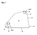
- FIG. 3 shows a holding device according to the invention 23.
- This has a flat bottom 24 from which two fasteners 25 and 26 protrude in the form of mounting pins 27 and 28, which form a fastening device 29.
- the mounting pins 27 and 28 are arranged on the holding device 23 so that they can pass through the mounting holes 2 and 3 of the diegelabdeckblechs 1.
- On the underside 24 of the holding device 23 facing away from the top 30 is provided analogously to the holding device 4, the connecting element 8 with the recess 9 and the overlapping elements 10 for attachment to the casement. This is however in FIG. 3 not shown.
- the underside 24 of the holding device 23 is, except for the fastening pins 27 and 28, designed flat so that they can rest over the entire surface on the surface 22 of the copegelabdeckblechs 1.
- the fastening pins 27 and 28 pass through the mounting holes 2 and 3, so that they over the outside 13 of the copegelabdeckblechs 1 protrude.
- the fastening pins 27 and 28 are designed as solid pins 31.
- the mounting pins 27 and 28 are formed in the manufacturing process of the holding device 23 with. The production is provided in an injection molding process, so that the holding device 23 with the integrally formed thereon fastening pins 27 and 28 form a plastic injection molded part 32.
- FIG. 4 It is shown how the holding device 23 is arranged on the copegelabdeckblech 1 before the mounting pins 27 and 28 are deformed. It can clearly be seen that the fastening pins 27 and 28 with ends 33 and 34 protrude beyond the outer side 13 of the copegelabdeckblechs 1. In this state, ie in front of the deforming provided for the holding device, the fastening pins 27 and 28 have substantially the same diameter as the fastening holes 2 and 3.
- the holding device 23 lies with its underside 24 in the in FIG. 4 illustrated state plan on the surface 22 of the copelabdeckblechs 1. The plane resting prevented tilting of the holding device 23 relative to the copegelabdeckblech 1, even under load.
- FIG. 5 shows the mounting pins 27 and 28 of the holding device 23 in a state in which the holding device 23 is permanently attached to the copegelabdeckblech 1.
- the ends 33 and 34 are deformed, so consist of deformed plastic material of the mounting pins 27 and 28.
- the deformation can be formed by riveting or Vertaumeln. In the illustrated example, the deformation was performed by riveting.
- the ends 33 and 34 of the mounting pins 27 and 28 thus form Rear grip elements 35 and 36. These have a larger diameter than the mounting holes 2 and 3 of the diegelabdeckblechs 1 so that passage through them is no longer possible.
- the holding device 23 is permanently and securely held on the copelabdeckblech 1.
- the rear grip elements 35 and 36 may also be provided on the outer side 13 of the diegelabdeckblechs 1, so do not need as in the in the Figures 1 and 2 State of the art shown on the side facing away from the outside 13 are provided. In order to improve the visual impression it can also be provided to tune the fastening pins 27 and 28 and thus the rear grip elements 35 and 36 in color to the wing cover plate 1 or the outer side 13.
Landscapes
- Engineering & Computer Science (AREA)
- Architecture (AREA)
- Civil Engineering (AREA)
- Structural Engineering (AREA)
- Wing Frames And Configurations (AREA)
Abstract
Description
- Die Erfindung betrifft ein Wohndachfenster mit einem Flügelrahmen, an dem mittels mindestens einer Haltevorrichtung mindestens ein Flügelabdeckblech lösbar befestigt ist, wobei die Haltevorrichtung an dem Flügelabdeckblech mittels mindestens einer Befestigungsvorrichtung permanent befestigt ist, die mindestens ein Befestigungselement aufweist, das ein Befestigungsloch des Flügelabdeckblechs durchgreift und dessen über die Außenseite des Flügelabdeckblechs ragendes Ende ein Hintergriffelement besitzt.
- Aus dem Stand der Technik sind Wohndachfenster bekannt, bei welchen die Haltevorrichtung mittels einer Schraubverbindung an dem Flügelabdeckblech befestigt ist. Ebenso ist die vorteilhafte Ausgestaltung bekannt, dass die Befestigung durch Nieten erfolgt. Zu diesem Zweck ist mindestens eine Niete beziehungsweise mindestens eine Schraube, beispielsweise zwei, vorgesehen, die eine Ausnehmung der Haltevorrichtung und das Befestigungsloch des Flügelabdeckblechs durchgreift und dort befestigt ist. Dies kann im Fall der Niete durch das Hintergriffelement und im Fall der Schraube durch eine Schraubenmutter vorgesehen sein. Zur Befestigung der Haltevorrichtung an dem Flügelabdeckblech sind also stets Befestigungselemente notwendig, beispielsweise Schrauben oder Nieten, die während des Befestigungsvorgangs in Ausnehmungen der Haltevorrichtung und Befestigungslöcher des Flügelabdeckblechs eingebracht und dort befestigt werden müssen.
- Es ist demgegenüber Aufgabe der Erfindung, ein Wohndachfenster vorzuschlagen, bei welchem die Befestigung der Haltevorrichtung an dem Flügelabdeckblech einfach herstellbar ist.
- Dies wird erfindungsgemäß mit einem Wohndachfenster erreicht, welches die Merkmale des Anspruchs 1 aufweist. Dabei ist vorgesehen, dass das Befestigungselement als Befestigungszapfen einstückig mit der aus Kunststoff bestehenden Haltevorrichtung ausgebildet ist und das Hintergriffelement von verformtem Kunststoffmaterial des Befestigungszapfens gebildet ist. Der Befestigungszapfen ist an der Haltevorrichtung integriert und dabei einstückig mit dieser ausgebildet. Das Hintergriffelement aus verformtem Kunststoffmaterial ragt über die Außenseite des Flügelabdeckblechs heraus. Das verformte Kunststoffmaterial ist insbesondere so ausgebildet, dass sich ein guter optischer Eindruck ergibt. Dies war mit den aus dem Stand der Technik bekannten Nieten nicht möglich, sodass diese stets mit ihrem vorausgebildeten Nietkopf auf der Außenseite des Flügelabdeckblechs angeordnet werden mussten. Das verformte Nietenmaterial war somit haltevorrichtungsseitig vorgesehen. Durch die Verwendung des einstückig mit der Haltevorrichtung ausgebildeten Befestigungszapfens entfallen die Nieten, sodass eine metalllose Verbindung möglich ist. Auch kann die Verformung des Kunststoffmaterials derart erfolgen, dass auch auf der Außenseite des Flügelabdeckblechs ein einwandfreier optischer Eindruck erzielbar ist. Insbesondere kann dabei farbiger Kunststoff verwendet werden, die Farbe des Befestigungszapfens also auf das Material beziehungsweise die Farbe des Flügelabdeckblechs abgestimmt sein. Das verformte Kunststoffmaterial bildet das Hintergriffelement, hält also den Befestigungszapfen durch Hintergriff an dem Flügelabdeckblech, indem auf dessen Außenseite der Befestigungszapfen verformt, insbesondere aufgeweitet, wird. Der Befestigungszapfen kann als Befestigungsstutzen ausgeführt sein, also insbesondere eine zylindrische Form aufweisen. Durch die Verwendung des integrierten Befestigungszapfens ist eine einfachere Montage der Haltevorrichtung während der Herstellung des Wohndachfensters möglich, da die zusätzlichen, nicht integrierten Befestigungselemente - beispielsweise Nieten - entfallen und somit eingespart werden können. Auch wird die Haltevorrichtung durch das Verformen des Befestigungszapfens nicht derart verformt, dass es zu Verspannungen und Brüchen, insbesondere der Haltevorrichtung, kommen kann, wie diese bei einer Befestigung mittels Nieten durchaus auftreten können. Somit ergibt sich eine Verbindung zwischen Haltevorrichtung und Flügelabdeckblech, welche einfach und preisgünstig herstellbar ist, insbesondere dadurch, dass die Verbindung metalllos ist und daher keine Beschichtung, beispielsweise des Befestigungselements, notwendig ist. Die Länge des Befestigungszapfens beziehungsweise die Länge des über die Außenseite des Flügelabdeckblechs ragenden Endes ist sowohl auf das Flügelabdeckblech als auch auf die Verformungsmethode abgestimmt. Dabei ist die Länge insbesondere so vorgesehen, dass kein Kürzen des Endes notwendig ist, sondern unmittelbar nach dem Durchgreifen des Befestigungsloches der Befestigungszapfen verformt werden kann. Trotz der einstückigen Ausbildung des Befestigungszapfens mit der Haltevorrichtung kann der Befestigungszapfen aus einem anderen Kunststoffmaterial bestehen als die Haltevorrichtung. Damit kann der Kunststoff des Befestigungszapfens auf die zur Herstellung der Verbindung notwendige Verformung abgestimmt sein. Beispielsweise ist ein Kunststoff vorgesehen, der nach der Verformung nicht nachgibt. Die Herstellung einer solchen Haltevorrichtung aus mehreren unterschiedlichen Kunststoffmaterialien kann in einem mehrphasigen Herstellungsprozess erfolgen. Die Haltevorrichtung kann zur Erhöhung ihrer Stabilität im Bereich der Befestigungszapfen Verdickungen beziehungsweise Verstärkungen aufweisen, also beispielsweise auf der dem Flügelabdeckblech gegenüberliegenden Seite im Bereich der Befestigungszapfen stärker ausgebildet sein.
- Eine vorteilhafte Weiterbildung der Erfindung sieht vor, dass der Befestigungszapfen als Vollzapfen oder als Hohlzapfen ausgebildet ist. Der Befestigungszapfen kann beispielsweise einen kreisrunden oder ovalen Querschnitt aufweisen, insbesondere bevor er zur Befestigung der Haltevorrichtung verformt wird. Häufig wird der Befestigungszapfen eine im Wesentlichen zylindrische Form aufweisen. Er kann aus vollem Material als Vollzapfen oder mit einem Hohlraum als Hohlzapfen ausgebildet sein. Beispielsweise kann der Befestigungszapfen in Form eines Hohlzylinders vorliegen. Es ist auch möglich, dass der Befestigungszapfen bereichsweise als Vollzapfen und bereichsweise als Hohlzapfen ausgebildet ist. Zu diesem Zweck kann beispielsweise der Hohlzapfen ein- oder beidseitig verschlossen sein und somit in diesem Bereich beziehungsweise diesen Bereichen einen Vollzapfen bilden.
- Eine weitere Ausgestaltung der Erfindung sieht vor, dass die Verformung mittels Vernieten oder Vertaumeln ausgebildet ist. Das Vernieten kann beispielsweise durch Verquetschen des Befestigungszapfens in dessen Längsrichtung vorgesehen sein. Bei dem Vernieten wird das über die Außenseite des Flügelabdeckblechs ragende Ende so verformt, dass es zumindest bereichsweise größere Abmessungen aufweist als das Befestigungsloch des Flügelabdeckblechs. Auf diese Weise ist ein Hindurchrutschen des verformten Endes durch dieses nicht mehr möglich und die Haltevorrichtung ist sicher an dem Flügelabdeckblech gehalten. Die Verformung kann jedoch auch durch Vertaumeln verursacht sein. Dies bedeutet, dass der Befestigungszapfen an dem über die Außenseite des Flügelabdeckblechs ragenden Ende mit einem rotierenden beziehungsweise exzentrisch rotierenden Werkzeug derart beaufschlagt wird, dass sich eine Verformung einstellt, die ein Herausbewegen des Endes durch das Befestigungsloch verhindert. Die Verformung des Kunststoffmaterials des Befestigungszapfens kann ebenso durch das Ein- oder Aufstecken von Kopfelementen vorgesehen sein. Beispielsweise kann in einem als Hohlzapfen ausgebildeten Befestigungszapfen ein Kopfelement in Form eines, insbesondere einen Kopf aufweisenden, Stifts eingebracht werden, wobei der Stift einen größeren Durchmesser als den Innendurchmesser des Hohlzapfens aufweist. Auf diese Weise wird das Kopfelement durch die Verformung des Kunststoffmaterials in dem Befestigungszapfen gehalten, wobei das verformte Kunststoffelement das Hintergriffelement bildet und ein Herausbewegen des Befestigungszapfens aus dem Befestigungsloch des Flügelabdeckblechs verhindert. Ebenso kann ein Aufstecken des Kopfelements vorgesehen sein, sodass das Kopfelement die Verformung des Befestigungszapfens bewirkt und den Befestigungszapfen zumindest bereichsweise umgreift.
- In einer bevorzugten Weiterbildung ist vorgesehen, dass die Haltevorrichtung zur lösbaren Befestigung ein Verbindungselement aufweist. Die Haltevorrichtung ist lösbar an dem Flügelrahmen befestigt, um die lösbare Befestigung des Flügelabdeckblechs an dem Flügelrahmen herzustellen. Zu diesem Zweck ist das Verbindungselement vorgesehen, welches die lösbare Befestigung der Haltevorrichtung an dem Flügelrahmen ermöglicht. Die Haltevorrichtung ist also lediglich an dem Flügelabdeckblech dauerhaft beziehungsweise permanent befestigt, bevorzugt jedoch nicht an dem Flügelrahmen. Auf diese Weise kann ein einfaches Austauschen des Flügelabdeckblechs erfolgen, indem das Flügelabdeckblech von dem Flügelrahmen entfernt und ein neues Flügelabdeckblech an diesem befestigt wird. Das Verbindungselement ermöglicht also vorzugsweise ein beschädigungsfreies Lösen der Befestigung.
- Nach einer vorteilhaften Weiterbildung der Erfindung ist vorgesehen, dass das Verbindungselement eine Formschlussverbindung vorsieht. Besonders einfach lässt sich das beschädigungsfreie Lösen der Haltevorrichtung von dem Flügelrahmen mittels einer Formschlussverbindung realisieren. Das bedeutet, dass die Haltevorrichtung mit einem Gegenelement des Flügelrahmens beispielsweise verrastet oder verklipst wird.
- Eine Weiterbildung der Erfindung sieht vor, dass der Befestigungszapfen beim Herstellprozess der Haltevorrichtung mit ausgebildet ist. Der Befestigungszapfen ist also nicht nur einstückig beziehungsweise integriert mit der Haltevorrichtung vorgesehen, er wird auch beim Herstellprozess derselben ausgebildet. Das heißt, dass im Anschluss des Herstellprozesses der Haltevorrichtung die Haltevorrichtung mit daran ausgebildetem Befestigungszapfen vorliegt. Es muss also kein weiterer Herstellungsschritt vorgesehen werden, um den Befestigungszapfen an der Haltevorrichtung vorzusehen beziehungsweise in diese zu integrieren. Beispielsweise kann dabei auch ein Mehrkomponenten-Prozess eingesetzt werden, um den Befestigungszapfen aus einem anderen Kunststoff zu fertigen als die Haltevorrichtung.
- Eine weitere Ausgestaltung der Erfindung sieht vor, dass die Haltevorrichtung mit Befestigungszapfen ein Kunststoffspritzgussteil ist. Die Haltevorrichtung wird also mit dem integrierten Befestigungszapfen in einem Spritzgussverfahren aus Kunststoff hergestellt.
- Die Erfindung wird im Folgenden anhand der in der Zeichnung dargestellten Ausführungsbeispiele näher erläutert, ohne dass eine Beschränkung der Erfindung erfolgt. Es zeigen:
- Figur 1
- ein Flügelabdeckblech und eine aus dem Stand der Technik bekannte Haltevorrichtung, die mittels Nieten befestigt wird,
- Figur 2
- die mittels Nieten an dem Flügelabdeckblech befestigte Haltevorrichtung,
- Figur 3
- eine erfindungsgemäße Haltevorrichtung mit einstückig daran ausgebildeten Befestigungszapfen,
- Figur 4
- das Flügelabdeckblech, wobei Befestigungszapfen der erfindungsgemäßen Haltevorrichtung Befestigungslö- cher des Flügelabdeckblechs durchgreifen, und
- Figur 5
- das Flügelabdeckblech und die erfindungsgemäße Hal- tevorrichtung, wobei die über die Außenseite des Flü- gelabdeckblechs ragenden Enden der Haltevorrichtung Hintergriffelemente aufweisen, die aus verformtem Kunststoffmaterial des Befestigungszapfens gebildet sind.
- Die
Figur 1 zeigt ausschnittsweise ein Flügelabdeckblech 1 mit zwei Befestigungslöchern 2 und 3. An diesen ist eine aus dem Stand der Technik bekannten Haltevorrichtung 4 mittels Nieten 5 befestigbar. - Die Haltevorrichtung 4 weist zu diesem Zweck Ausnehmungen 6 und 7 auf. Die Haltevorrichtung 4 weist weiterhin ein Verbindungselement 8 auf, mittels welcher eine Formschlussverbindung zu einem nicht dargestellten Flügelrahmen hergestellt werden kann. Zu diesem Zweck wird ein Bereich des Flügelrahmens in eine Aussparung 9 des Verbindungselements 8 eingebracht und dort formschlüssig befestigt, beispielsweise durch Verklemmen, Verrasten oder Einklipsen. Die Aussparung 9 weist dazu in dem dargestellten Beispiel beidseitig schienenförmige Übergriffelemente 10 auf, die von Bereichen des Flügelrahmens zumindest bereichsweise hintergriffen sind und somit eine sichere aber lösbare Befestigung der Haltevorrichtung 4 an dem Flügelrahmen erlauben.
- Die Nieten 5 weisen auf einer Seite einen Nietkopf 11 auf, welcher in Querschnitt halblinsenförmig ist. Auf diese Weise entsteht eine Nietkopfauflagefläche 12, mit welcher der Nietkopf 11 auf einer Außenseite 13 des Flügelabdeckblechs nach dem Befestigen aufliegt. Der Nietkopf 11 weist einen größeren Durchmesser auf als die Befestigungslöcher 2 und 3, sodass ein Hindurchtreten des Nietkopfes 11 durch diese nicht möglich ist. An den Nietkopf 11 schließt sich ein Nietkörper 14 an, der in diesem Fall hohlzylinderförmig ausgebildet ist.
-
Figur 2 zeigt die an dem Flügelabdeckblech 1 befestigte Haltevorrichtung 4. Dabei sind die Ausnehmungen 6 und 7 der Haltevorrichtung 4 über den Befestigungslöchern 2 und 3 (inFigur 2 nicht mehr sichtbar) angeordnet. Die Haltevorrichtung 4 ist mit zwei Nieten 5 an dem Flügelabdeckblech 1 befestigt, welche eine Befestigungsvorrichtung 15 darstellen. Dazu durchgreift jeweils eine Niete das Befestigungsloch 2 und die Ausnehmung 6 beziehungsweise das Befestigungsloch 3 und die Ausnehmung 7. Der Nietkopf 11 der Nieten 5 ist dabei auf der Außenseite 13 (inFigur 2 nicht sichtbar) des Flügelabdeckblechs 1 positioniert. Die Nieten 5 sind so verformt, dass der inFigur 1 erkennbare Nietkörper 14 an einem über eine Außenseite 16 der Haltevorrichtung 4 ragenden Ende 17 verformt ist und einen Nietrand 18 ausbildet. Der Nietrand 18 weist einen Durchmesser auf, der größer ist als der Durchmesser der Ausnehmungen 6 beziehungsweise 7. Die Nietränder 18 der Nieten 5 bilden Hintergriffelemente 19 und 20. Auf diese Weise ist die Haltevorrichtung 4 permanent an dem Flügelabdeckblech 1 befestigt. Dabei liegt die Haltevorrichtung 4 mit einer Unterseite 21 auf einer Oberfläche 22 des Flügelabdeckblechs 1 plan auf. - Die
Figur 3 zeigt eine erfindungsgemäße Haltevorrichtung 23. Diese weist eine plane Unterseite 24 auf, aus der zwei Befestigungselemente 25 und 26 in der Form von Befestigungszapfen 27 und 28 herausragen, die eine Befestigungsvorrichtung 29 bilden. Die Befestigungszapfen 27 und 28 sind so auf der Haltevorrichtung 23 angeordnet, dass sie die Befestigungslöcher 2 und 3 des Flügelabdeckblechs 1 durchgreifen können. Auf der der Unterseite 24 der Haltevorrichtung 23 abgewandten Oberseite 30 ist analog zu der Haltevorrichtung 4 das Verbindungselement 8 mit der Aussparung 9 und den Übergriffelementen 10 zur Befestigung an dem Flügelrahmen vorgesehen. Dies ist jedoch inFigur 3 nicht dargestellt. - Die Unterseite 24 der Haltevorrichtung 23 ist, abgesehen von den Befestigungszapfen 27 und 28, plan ausgebildet, sodass sie vollflächig auf der Oberfläche 22 des Flügelabdeckblechs 1 aufliegen kann. In diesem Zustand durchgreifen die Befestigungszapfen 27 und 28 die Befestigungslöcher 2 und 3, sodass sie über die Außenseite 13 des Flügelabdeckblechs 1 hinausragen. Deutlich erkennbar ist, dass die Befestigungszapfen 27 und 28 als Vollzapfen 31 ausgebildet sind. Die Befestigungszapfen 27 und 28 sind beim Herstellprozess der Haltevorrichtung 23 mit ausgebildet. Dabei ist die Herstellung in einem Spritzgussverfahren vorgesehen, sodass die Haltevorrichtung 23 mit den einstückig daran ausgebildeten Befestigungszapfen 27 und 28 ein Kunststoffspritzgussteil 32 bilden.
- In
Figur 4 ist gezeigt, wie die Haltevorrichtung 23 an dem Flügelabdeckblech 1 angeordnet ist, bevor die Befestigungszapfen 27 und 28 verformt werden. Deutlich ist erkennbar, dass die Befestigungszapfen 27 und 28 mit Enden 33 und 34 über die Außenseite 13 des Flügelabdeckblechs 1 hinausragen. In diesem Zustand, also vor dem zur Befestigung der Haltevorrichtung vorgesehenen Verformen, weisen die Befestigungszapfen 27 und 28 im Wesentlichen denselben Durchmesser auf wie die Befestigungslöcher 2 und 3. Wie bereits erwähnt liegt die Haltevorrichtung 23 mit ihrer Unterseite 24 in dem inFigur 4 dargestellten Zustand plan auf der Oberfläche 22 des Flügelabdeckblechs 1 auf. Das plane Aufliegen verhinderte ein Verkippen der Haltevorrichtung 23 gegenüber dem Flügelabdeckblech 1, auch unter Belastung. - Die
Figur 5 zeigt die Befestigungszapfen 27 und 28 der Haltevorrichtung 23 in einem Zustand, in dem die Haltevorrichtung 23 permanent an dem Flügelabdeckblech 1 befestigt ist. Dazu sind die Enden 33 und 34 verformt, bestehen also aus verformtem Kunststoffmaterial der Befestigungszapfen 27 und 28. Die Verformung kann mittels Vernieten oder Vertaumeln ausgebildet sein. In dem dargestellten Beispiel wurde die Verformung mittels Vernieten durchgeführt. Die Enden 33 und 34 der Befestigungszapfen 27 und 28 bilden somit Hintergriffelemente 35 und 36. Diese weisen einen größeren Durchmesser auf als die Befestigungslöcher 2 und 3 des Flügelabdeckblechs 1, sodass ein Hindurchtreten durch diese nicht mehr möglich ist. Damit ist die Haltevorrichtung 23 permanent und sicher an dem Flügelabdeckblech 1 gehalten. - Bei dem Verformen beziehungsweise Vernieten der Befestigungszapfen 27 und 28 werden diese so verformt, dass sie einen linsenförmigen Querschnitt aufweisen. Auf diese Weise liegt ein hervorragender optischer Eindruck vor. Somit können die Hintergriffelemente 35 und 36 auch auf der Außenseite 13 des Flügelabdeckblechs 1 vorgesehen sein, müssen also nicht wie bei dem in den
Figuren 1 und 2 dargestellten Stand der Technik auf der der Außenseite 13 abgewandten Seite vorgesehen werden. Um den optischen Eindruck noch zu verbessern kann es auch vorgesehen sein, die Befestigungszapfen 27 und 28 und damit die Hintergriffelemente 35 und 36 farblich auf das Flügelabdeckblech 1 beziehungsweise die Außenseite 13 abzustimmen. Durch die integrale Ausbildung der Befestigungszapfen 27 und 28 an der Haltevorrichtung 23 beziehungsweise die einstückige Ausführung ist eine einfache Montage der Haltevorrichtung 23 an dem Flügelabdeckblech 1 gewährleistet, da zusätzliche Befestigungselemente, wie die inFigur 1 und 2 dargestellten Nieten 5, entfallen und somit eingespart werden können. - Ebenso können keine Verspannungen und Brüche der Haltevorrichtung 23 bedingt durch die zusätzlichen Befestigungselemente auftreten. Auch ist keine Beschichtung notwendig, da die Haltevorrichtung 23 und die Befestigungszapfen 27 und 28 vollständig aus Kunststoff bestehen und damit eine metalllose Verbindung zwischen Flügelabdeckblech 1 und dem Flügelrahmen ermöglichen.
Claims (7)
- Wohndachfenster mit einem Flügelrahmen, an dem mittels mindestens einer Haltevorrichtung (4,23) mindestens ein Flügelabdeckblech (1) lösbar befestigt ist, wobei die Haltevorrichtung (4,23) an dem Flügelabdeckblech (1) mittels mindestens einer Befestigungsvorrichtung (15,29) permanent befestigt ist, die mindestens ein Befestigungselement (5,25,26) aufweist, das ein Befestigungsloch (2,3) des Flügelabdeckblechs (1) durchgreift und dessen über die Außenseite (13) des Flügelabdeckblechs (1) ragendes Ende (33,34) ein Hintergriffelement (11,35,36) besitzt, dadurch gekennzeichnet, dass das Befestigungselement (25,26) als Befestigungszapfen (27,28) einstückig mit der aus Kunststoff bestehenden Haltevorrichtung (23) ausgebildet ist und das Hintergriffelement (35,36) von verformtem Kunststoffmaterial des Befestigungszapfens (27,28) gebildet ist.
- Wohndachfenster nach Anspruch 1, dadurch gekennzeichnet, dass der Befestigungszapfen (27,28) als Vollzapfen (31) oder als Hohlzapfen ausgebildet ist.
- Wohndachfenster nach einem der vorhergehenden Ansprüche, dadurch gekennzeichnet, dass die Verformung mittels Vernieten oder Vertaumeln ausgebildet ist.
- Wohndachfenster nach einem der vorhergehenden Ansprüche, dadurch gekennzeichnet, dass die Haltevorrichtung (4,23) zur lösbaren Befestigung ein Verbindungselement (8) aufweist.
- Wohndachfenster nach einem der vorhergehenden Ansprüche, dadurch gekennzeichnet, dass das Verbindungselement (8) eine Formschlussverbindung vorsieht.
- Wohndachfenster nach einem der vorhergehenden Ansprüche, dadurch gekennzeichnet, dass der Befestigungszapfen (27,28) beim Herstellprozess der Haltevorrichtung (23) mit ausgebildet ist.
- Wohndachfenster nach einem der vorhergehenden Ansprüche, dadurch gekennzeichnet, dass die Haltevorrichtung (23) mit Befestigungszapfen (27,28) ein Kunststoffspritzgussteil (32) ist.
Applications Claiming Priority (1)
| Application Number | Priority Date | Filing Date | Title |
|---|---|---|---|
| DE200910004994 DE102009004994B4 (de) | 2009-01-17 | 2009-01-17 | Wohndachfenster mit einem Flügelrahmen |
Publications (3)
| Publication Number | Publication Date |
|---|---|
| EP2208847A2 true EP2208847A2 (de) | 2010-07-21 |
| EP2208847A3 EP2208847A3 (de) | 2013-05-15 |
| EP2208847B1 EP2208847B1 (de) | 2015-09-30 |
Family
ID=42083685
Family Applications (1)
| Application Number | Title | Priority Date | Filing Date |
|---|---|---|---|
| EP10000242.7A Active EP2208847B1 (de) | 2009-01-17 | 2010-01-13 | Befestigung eines Abdeckbleches an einem Dachfensterrahmen |
Country Status (2)
| Country | Link |
|---|---|
| EP (1) | EP2208847B1 (de) |
| DE (1) | DE102009004994B4 (de) |
Family Cites Families (2)
| Publication number | Priority date | Publication date | Assignee | Title |
|---|---|---|---|---|
| US3349536A (en) * | 1963-12-31 | 1967-10-31 | Riv Kap Inc | Frame joint and fastener therefor |
| DE10217532A1 (de) * | 2002-04-17 | 2003-11-13 | Roto Frank Ag | Dachfenster mit geklipster Abdeckung |
-
2009
- 2009-01-17 DE DE200910004994 patent/DE102009004994B4/de not_active Expired - Fee Related
-
2010
- 2010-01-13 EP EP10000242.7A patent/EP2208847B1/de active Active
Non-Patent Citations (1)
| Title |
|---|
| None |
Also Published As
| Publication number | Publication date |
|---|---|
| EP2208847B1 (de) | 2015-09-30 |
| DE102009004994B4 (de) | 2012-02-02 |
| DE102009004994A1 (de) | 2010-07-22 |
| EP2208847A3 (de) | 2013-05-15 |
Similar Documents
| Publication | Publication Date | Title |
|---|---|---|
| EP2382905A2 (de) | Hohlprofil | |
| DE202013001957U1 (de) | Betätigungshandhabe | |
| DE102012208482A1 (de) | Befestigungsvorrichtung | |
| DE102015112563A1 (de) | Verbindungsanordnung zum Verbinden eines Pfostens an einem Rahmenprofil eines Fensters oder einer Türe aus Kunststoff | |
| DE19934842A1 (de) | Beschlag für die Verriegelung von Fenstern oder Türen | |
| EP3557084A1 (de) | Verbindungselement zum verbinden von profilelementen | |
| EP3333351A1 (de) | Verbindungsanordnung zum verbinden eines pfostens mit einem rahmenprofil eines fensters oder einer türe aus kunststoff | |
| DE102014119021B4 (de) | Anordnung zum Befestigen eines Pfostens aus Kunststoff an einer Rahmenleiste eines Fensters oder einer Türe mittels eines Pfostenverbinders | |
| DE102018122142B4 (de) | Klemmaufnahme und Bandtasche | |
| DE102009018781B4 (de) | Verbindungsbaugruppe | |
| EP2208847B1 (de) | Befestigung eines Abdeckbleches an einem Dachfensterrahmen | |
| DE3242077C2 (de) | Halterung zum Befestigen eines Steckverbinders, vorzugsweise an einer Flugzeugstruktur | |
| DE102013208494A1 (de) | Vorrichtung zur werkzeuglosen Verbindung zweier Bauteile | |
| DE102012007771A1 (de) | Montageplattenhalter für einen Schaltschrank | |
| DE202010013558U1 (de) | Scharnier für ein Insekten- und/oder Pollenschutzgitter | |
| DE102010024411A1 (de) | Befestigungsvorrichtung, insbesondere für ein Interieur-Ausstattungsteil in Kraftfahrzeugen | |
| EP2226572A2 (de) | Vorrichtung zum Haltern eines Heizkörpers | |
| DE102010003007A1 (de) | Abdeckanordnung | |
| EP1428941B1 (de) | Anordnung zur Anbringung eines Sanitärgegenstands | |
| EP3406916B1 (de) | Winkelverbinder für tragprofile | |
| DE29812639U1 (de) | Schließblech | |
| AT527376B1 (de) | Schubladenseitenwand für eine Schublade | |
| DE102014100757A1 (de) | Tür- und/oder Fensterbeschlag-Befestigungsvorrichtung | |
| DE2534375C2 (de) | Stiftförmige Vorrichtung zum federnden Verspannen zweier Bauteile | |
| EP1462049A2 (de) | Befestigungsvorrichtung für eine Arbeitsplatte |
Legal Events
| Date | Code | Title | Description |
|---|---|---|---|
| PUAI | Public reference made under article 153(3) epc to a published international application that has entered the european phase |
Free format text: ORIGINAL CODE: 0009012 |
|
| AK | Designated contracting states |
Kind code of ref document: A2 Designated state(s): AT BE BG CH CY CZ DE DK EE ES FI FR GB GR HR HU IE IS IT LI LT LU LV MC MK MT NL NO PL PT RO SE SI SK SM TR |
|
| AX | Request for extension of the european patent |
Extension state: AL BA RS |
|
| PUAL | Search report despatched |
Free format text: ORIGINAL CODE: 0009013 |
|
| AK | Designated contracting states |
Kind code of ref document: A3 Designated state(s): AT BE BG CH CY CZ DE DK EE ES FI FR GB GR HR HU IE IS IT LI LT LU LV MC MK MT NL NO PL PT RO SE SI SK SM TR |
|
| AX | Request for extension of the european patent |
Extension state: AL BA RS |
|
| RIC1 | Information provided on ipc code assigned before grant |
Ipc: E04D 13/035 20060101ALI20130409BHEP Ipc: E06B 3/30 20060101AFI20130409BHEP |
|
| 17P | Request for examination filed |
Effective date: 20131115 |
|
| RBV | Designated contracting states (corrected) |
Designated state(s): AT BE BG CH CY CZ DE DK EE ES FI FR GB GR HR HU IE IS IT LI LT LU LV MC MK MT NL NO PL PT RO SE SI SK SM TR |
|
| GRAP | Despatch of communication of intention to grant a patent |
Free format text: ORIGINAL CODE: EPIDOSNIGR1 |
|
| INTG | Intention to grant announced |
Effective date: 20150512 |
|
| GRAS | Grant fee paid |
Free format text: ORIGINAL CODE: EPIDOSNIGR3 |
|
| GRAA | (expected) grant |
Free format text: ORIGINAL CODE: 0009210 |
|
| AK | Designated contracting states |
Kind code of ref document: B1 Designated state(s): AT BE BG CH CY CZ DE DK EE ES FI FR GB GR HR HU IE IS IT LI LT LU LV MC MK MT NL NO PL PT RO SE SI SK SM TR |
|
| REG | Reference to a national code |
Ref country code: CH Ref legal event code: EP Ref country code: GB Ref legal event code: FG4D Free format text: NOT ENGLISH |
|
| REG | Reference to a national code |
Ref country code: AT Ref legal event code: REF Ref document number: 752533 Country of ref document: AT Kind code of ref document: T Effective date: 20151015 |
|
| REG | Reference to a national code |
Ref country code: IE Ref legal event code: FG4D Free format text: LANGUAGE OF EP DOCUMENT: GERMAN |
|
| REG | Reference to a national code |
Ref country code: DE Ref legal event code: R096 Ref document number: 502010010437 Country of ref document: DE |
|
| REG | Reference to a national code |
Ref country code: CH Ref legal event code: NV Representative=s name: OFFICE ERNEST T. FREYLINGER S.A., CH |
|
| PG25 | Lapsed in a contracting state [announced via postgrant information from national office to epo] |
Ref country code: LV Free format text: LAPSE BECAUSE OF FAILURE TO SUBMIT A TRANSLATION OF THE DESCRIPTION OR TO PAY THE FEE WITHIN THE PRESCRIBED TIME-LIMIT Effective date: 20150930 Ref country code: GR Free format text: LAPSE BECAUSE OF FAILURE TO SUBMIT A TRANSLATION OF THE DESCRIPTION OR TO PAY THE FEE WITHIN THE PRESCRIBED TIME-LIMIT Effective date: 20151231 Ref country code: NO Free format text: LAPSE BECAUSE OF FAILURE TO SUBMIT A TRANSLATION OF THE DESCRIPTION OR TO PAY THE FEE WITHIN THE PRESCRIBED TIME-LIMIT Effective date: 20151230 Ref country code: LT Free format text: LAPSE BECAUSE OF FAILURE TO SUBMIT A TRANSLATION OF THE DESCRIPTION OR TO PAY THE FEE WITHIN THE PRESCRIBED TIME-LIMIT Effective date: 20150930 Ref country code: FI Free format text: LAPSE BECAUSE OF FAILURE TO SUBMIT A TRANSLATION OF THE DESCRIPTION OR TO PAY THE FEE WITHIN THE PRESCRIBED TIME-LIMIT Effective date: 20150930 |
|
| REG | Reference to a national code |
Ref country code: NL Ref legal event code: MP Effective date: 20150930 |
|
| REG | Reference to a national code |
Ref country code: LT Ref legal event code: MG4D |
|
| PG25 | Lapsed in a contracting state [announced via postgrant information from national office to epo] |
Ref country code: HR Free format text: LAPSE BECAUSE OF FAILURE TO SUBMIT A TRANSLATION OF THE DESCRIPTION OR TO PAY THE FEE WITHIN THE PRESCRIBED TIME-LIMIT Effective date: 20150930 Ref country code: SE Free format text: LAPSE BECAUSE OF FAILURE TO SUBMIT A TRANSLATION OF THE DESCRIPTION OR TO PAY THE FEE WITHIN THE PRESCRIBED TIME-LIMIT Effective date: 20150930 |
|
| PG25 | Lapsed in a contracting state [announced via postgrant information from national office to epo] |
Ref country code: IS Free format text: LAPSE BECAUSE OF FAILURE TO SUBMIT A TRANSLATION OF THE DESCRIPTION OR TO PAY THE FEE WITHIN THE PRESCRIBED TIME-LIMIT Effective date: 20160130 Ref country code: CZ Free format text: LAPSE BECAUSE OF FAILURE TO SUBMIT A TRANSLATION OF THE DESCRIPTION OR TO PAY THE FEE WITHIN THE PRESCRIBED TIME-LIMIT Effective date: 20150930 Ref country code: NL Free format text: LAPSE BECAUSE OF FAILURE TO SUBMIT A TRANSLATION OF THE DESCRIPTION OR TO PAY THE FEE WITHIN THE PRESCRIBED TIME-LIMIT Effective date: 20150930 Ref country code: EE Free format text: LAPSE BECAUSE OF FAILURE TO SUBMIT A TRANSLATION OF THE DESCRIPTION OR TO PAY THE FEE WITHIN THE PRESCRIBED TIME-LIMIT Effective date: 20150930 Ref country code: ES Free format text: LAPSE BECAUSE OF FAILURE TO SUBMIT A TRANSLATION OF THE DESCRIPTION OR TO PAY THE FEE WITHIN THE PRESCRIBED TIME-LIMIT Effective date: 20150930 Ref country code: IT Free format text: LAPSE BECAUSE OF FAILURE TO SUBMIT A TRANSLATION OF THE DESCRIPTION OR TO PAY THE FEE WITHIN THE PRESCRIBED TIME-LIMIT Effective date: 20150930 Ref country code: SK Free format text: LAPSE BECAUSE OF FAILURE TO SUBMIT A TRANSLATION OF THE DESCRIPTION OR TO PAY THE FEE WITHIN THE PRESCRIBED TIME-LIMIT Effective date: 20150930 |
|
| PG25 | Lapsed in a contracting state [announced via postgrant information from national office to epo] |
Ref country code: PL Free format text: LAPSE BECAUSE OF FAILURE TO SUBMIT A TRANSLATION OF THE DESCRIPTION OR TO PAY THE FEE WITHIN THE PRESCRIBED TIME-LIMIT Effective date: 20150930 Ref country code: BE Free format text: LAPSE BECAUSE OF NON-PAYMENT OF DUE FEES Effective date: 20160131 Ref country code: RO Free format text: LAPSE BECAUSE OF FAILURE TO SUBMIT A TRANSLATION OF THE DESCRIPTION OR TO PAY THE FEE WITHIN THE PRESCRIBED TIME-LIMIT Effective date: 20150930 Ref country code: PT Free format text: LAPSE BECAUSE OF FAILURE TO SUBMIT A TRANSLATION OF THE DESCRIPTION OR TO PAY THE FEE WITHIN THE PRESCRIBED TIME-LIMIT Effective date: 20160201 |
|
| REG | Reference to a national code |
Ref country code: DE Ref legal event code: R097 Ref document number: 502010010437 Country of ref document: DE |
|
| PLBE | No opposition filed within time limit |
Free format text: ORIGINAL CODE: 0009261 |
|
| STAA | Information on the status of an ep patent application or granted ep patent |
Free format text: STATUS: NO OPPOSITION FILED WITHIN TIME LIMIT |
|
| PG25 | Lapsed in a contracting state [announced via postgrant information from national office to epo] |
Ref country code: DK Free format text: LAPSE BECAUSE OF FAILURE TO SUBMIT A TRANSLATION OF THE DESCRIPTION OR TO PAY THE FEE WITHIN THE PRESCRIBED TIME-LIMIT Effective date: 20150930 Ref country code: LU Free format text: LAPSE BECAUSE OF FAILURE TO SUBMIT A TRANSLATION OF THE DESCRIPTION OR TO PAY THE FEE WITHIN THE PRESCRIBED TIME-LIMIT Effective date: 20160113 |
|
| 26N | No opposition filed |
Effective date: 20160701 |
|
| GBPC | Gb: european patent ceased through non-payment of renewal fee |
Effective date: 20160113 |
|
| PG25 | Lapsed in a contracting state [announced via postgrant information from national office to epo] |
Ref country code: MC Free format text: LAPSE BECAUSE OF FAILURE TO SUBMIT A TRANSLATION OF THE DESCRIPTION OR TO PAY THE FEE WITHIN THE PRESCRIBED TIME-LIMIT Effective date: 20150930 |
|
| REG | Reference to a national code |
Ref country code: FR Ref legal event code: ST Effective date: 20160930 |
|
| PG25 | Lapsed in a contracting state [announced via postgrant information from national office to epo] |
Ref country code: GB Free format text: LAPSE BECAUSE OF NON-PAYMENT OF DUE FEES Effective date: 20160113 |
|
| REG | Reference to a national code |
Ref country code: IE Ref legal event code: MM4A |
|
| PG25 | Lapsed in a contracting state [announced via postgrant information from national office to epo] |
Ref country code: FR Free format text: LAPSE BECAUSE OF NON-PAYMENT OF DUE FEES Effective date: 20160201 Ref country code: SI Free format text: LAPSE BECAUSE OF FAILURE TO SUBMIT A TRANSLATION OF THE DESCRIPTION OR TO PAY THE FEE WITHIN THE PRESCRIBED TIME-LIMIT Effective date: 20150930 |
|
| PG25 | Lapsed in a contracting state [announced via postgrant information from national office to epo] |
Ref country code: IE Free format text: LAPSE BECAUSE OF NON-PAYMENT OF DUE FEES Effective date: 20160113 |
|
| PGFP | Annual fee paid to national office [announced via postgrant information from national office to epo] |
Ref country code: CH Payment date: 20170119 Year of fee payment: 8 |
|
| PGFP | Annual fee paid to national office [announced via postgrant information from national office to epo] |
Ref country code: AT Payment date: 20170123 Year of fee payment: 8 |
|
| PG25 | Lapsed in a contracting state [announced via postgrant information from national office to epo] |
Ref country code: MT Free format text: LAPSE BECAUSE OF FAILURE TO SUBMIT A TRANSLATION OF THE DESCRIPTION OR TO PAY THE FEE WITHIN THE PRESCRIBED TIME-LIMIT Effective date: 20150930 |
|
| PG25 | Lapsed in a contracting state [announced via postgrant information from national office to epo] |
Ref country code: SM Free format text: LAPSE BECAUSE OF FAILURE TO SUBMIT A TRANSLATION OF THE DESCRIPTION OR TO PAY THE FEE WITHIN THE PRESCRIBED TIME-LIMIT Effective date: 20150930 Ref country code: CY Free format text: LAPSE BECAUSE OF FAILURE TO SUBMIT A TRANSLATION OF THE DESCRIPTION OR TO PAY THE FEE WITHIN THE PRESCRIBED TIME-LIMIT Effective date: 20150930 Ref country code: HU Free format text: LAPSE BECAUSE OF FAILURE TO SUBMIT A TRANSLATION OF THE DESCRIPTION OR TO PAY THE FEE WITHIN THE PRESCRIBED TIME-LIMIT; INVALID AB INITIO Effective date: 20100113 |
|
| PG25 | Lapsed in a contracting state [announced via postgrant information from national office to epo] |
Ref country code: MK Free format text: LAPSE BECAUSE OF FAILURE TO SUBMIT A TRANSLATION OF THE DESCRIPTION OR TO PAY THE FEE WITHIN THE PRESCRIBED TIME-LIMIT Effective date: 20150930 Ref country code: TR Free format text: LAPSE BECAUSE OF FAILURE TO SUBMIT A TRANSLATION OF THE DESCRIPTION OR TO PAY THE FEE WITHIN THE PRESCRIBED TIME-LIMIT Effective date: 20150930 |
|
| PG25 | Lapsed in a contracting state [announced via postgrant information from national office to epo] |
Ref country code: BG Free format text: LAPSE BECAUSE OF FAILURE TO SUBMIT A TRANSLATION OF THE DESCRIPTION OR TO PAY THE FEE WITHIN THE PRESCRIBED TIME-LIMIT Effective date: 20150930 |
|
| REG | Reference to a national code |
Ref country code: CH Ref legal event code: PL |
|
| REG | Reference to a national code |
Ref country code: AT Ref legal event code: MM01 Ref document number: 752533 Country of ref document: AT Kind code of ref document: T Effective date: 20180113 |
|
| PG25 | Lapsed in a contracting state [announced via postgrant information from national office to epo] |
Ref country code: CH Free format text: LAPSE BECAUSE OF NON-PAYMENT OF DUE FEES Effective date: 20180131 Ref country code: LI Free format text: LAPSE BECAUSE OF NON-PAYMENT OF DUE FEES Effective date: 20180131 Ref country code: AT Free format text: LAPSE BECAUSE OF NON-PAYMENT OF DUE FEES Effective date: 20180113 |
|
| PGFP | Annual fee paid to national office [announced via postgrant information from national office to epo] |
Ref country code: DE Payment date: 20260120 Year of fee payment: 17 |