EP2208830A1 - Rain water underdrain system and plant cultivation system equipped with rain water underdrain system - Google Patents
Rain water underdrain system and plant cultivation system equipped with rain water underdrain system Download PDFInfo
- Publication number
- EP2208830A1 EP2208830A1 EP08846884A EP08846884A EP2208830A1 EP 2208830 A1 EP2208830 A1 EP 2208830A1 EP 08846884 A EP08846884 A EP 08846884A EP 08846884 A EP08846884 A EP 08846884A EP 2208830 A1 EP2208830 A1 EP 2208830A1
- Authority
- EP
- European Patent Office
- Prior art keywords
- water
- rainwater
- plant cultivating
- plant
- reservoir
- Prior art date
- Legal status (The legal status is an assumption and is not a legal conclusion. Google has not performed a legal analysis and makes no representation as to the accuracy of the status listed.)
- Withdrawn
Links
- XLYOFNOQVPJJNP-UHFFFAOYSA-N water Substances O XLYOFNOQVPJJNP-UHFFFAOYSA-N 0.000 title claims abstract description 155
- 238000005086 pumping Methods 0.000 claims abstract description 33
- 230000002093 peripheral effect Effects 0.000 claims abstract description 10
- 238000007599 discharging Methods 0.000 claims abstract description 3
- 239000007787 solid Substances 0.000 claims description 7
- 239000000126 substance Substances 0.000 claims description 6
- 241000196324 Embryophyta Species 0.000 description 212
- 238000003860 storage Methods 0.000 description 120
- 230000036544 posture Effects 0.000 description 22
- 238000005192 partition Methods 0.000 description 12
- 239000002689 soil Substances 0.000 description 11
- 239000002184 metal Substances 0.000 description 10
- 238000007667 floating Methods 0.000 description 8
- 239000008399 tap water Substances 0.000 description 7
- 235000020679 tap water Nutrition 0.000 description 7
- 230000000694 effects Effects 0.000 description 5
- 238000010276 construction Methods 0.000 description 4
- 229920003002 synthetic resin Polymers 0.000 description 4
- 239000000057 synthetic resin Substances 0.000 description 4
- 238000011010 flushing procedure Methods 0.000 description 3
- 239000001963 growth medium Substances 0.000 description 3
- 239000000463 material Substances 0.000 description 3
- 238000000034 method Methods 0.000 description 3
- 238000007747 plating Methods 0.000 description 3
- 238000009423 ventilation Methods 0.000 description 3
- 229920002430 Fibre-reinforced plastic Polymers 0.000 description 2
- 238000009825 accumulation Methods 0.000 description 2
- 239000011151 fibre-reinforced plastic Substances 0.000 description 2
- 238000004519 manufacturing process Methods 0.000 description 2
- 239000008188 pellet Substances 0.000 description 2
- 239000005020 polyethylene terephthalate Substances 0.000 description 2
- 229920000139 polyethylene terephthalate Polymers 0.000 description 2
- -1 polypropylene Polymers 0.000 description 2
- 229920005989 resin Polymers 0.000 description 2
- 239000011347 resin Substances 0.000 description 2
- 230000000717 retained effect Effects 0.000 description 2
- 239000004576 sand Substances 0.000 description 2
- 241000195493 Cryptophyta Species 0.000 description 1
- 241001276618 Mayaca fluviatilis Species 0.000 description 1
- 239000004743 Polypropylene Substances 0.000 description 1
- 108010082455 Sebelipase alfa Proteins 0.000 description 1
- 239000000853 adhesive Substances 0.000 description 1
- 230000001070 adhesive effect Effects 0.000 description 1
- 238000000071 blow moulding Methods 0.000 description 1
- 239000012530 fluid Substances 0.000 description 1
- 239000006260 foam Substances 0.000 description 1
- 238000010102 injection blow moulding Methods 0.000 description 1
- 238000001746 injection moulding Methods 0.000 description 1
- 238000005304 joining Methods 0.000 description 1
- 229940041615 kanuma Drugs 0.000 description 1
- 239000011490 mineral wool Substances 0.000 description 1
- 238000000465 moulding Methods 0.000 description 1
- 229910001562 pearlite Inorganic materials 0.000 description 1
- 239000003415 peat Substances 0.000 description 1
- 239000005011 phenolic resin Substances 0.000 description 1
- 229920013716 polyethylene resin Polymers 0.000 description 1
- 229920001155 polypropylene Polymers 0.000 description 1
- 238000005381 potential energy Methods 0.000 description 1
- 238000010248 power generation Methods 0.000 description 1
- 238000009418 renovation Methods 0.000 description 1
- 238000009751 slip forming Methods 0.000 description 1
- 229910001220 stainless steel Inorganic materials 0.000 description 1
- 239000010935 stainless steel Substances 0.000 description 1
- 239000008400 supply water Substances 0.000 description 1
- 229920002803 thermoplastic polyurethane Polymers 0.000 description 1
- 229920005992 thermoplastic resin Polymers 0.000 description 1
- 229910052902 vermiculite Inorganic materials 0.000 description 1
- 235000019354 vermiculite Nutrition 0.000 description 1
- 239000010455 vermiculite Substances 0.000 description 1
Images











Classifications
-
- A—HUMAN NECESSITIES
- A01—AGRICULTURE; FORESTRY; ANIMAL HUSBANDRY; HUNTING; TRAPPING; FISHING
- A01G—HORTICULTURE; CULTIVATION OF VEGETABLES, FLOWERS, RICE, FRUIT, VINES, HOPS OR SEAWEED; FORESTRY; WATERING
- A01G25/00—Watering gardens, fields, sports grounds or the like
- A01G25/06—Watering arrangements making use of perforated pipe-lines located in the soil
-
- A—HUMAN NECESSITIES
- A01—AGRICULTURE; FORESTRY; ANIMAL HUSBANDRY; HUNTING; TRAPPING; FISHING
- A01G—HORTICULTURE; CULTIVATION OF VEGETABLES, FLOWERS, RICE, FRUIT, VINES, HOPS OR SEAWEED; FORESTRY; WATERING
- A01G27/00—Self-acting watering devices, e.g. for flower-pots
-
- A—HUMAN NECESSITIES
- A01—AGRICULTURE; FORESTRY; ANIMAL HUSBANDRY; HUNTING; TRAPPING; FISHING
- A01G—HORTICULTURE; CULTIVATION OF VEGETABLES, FLOWERS, RICE, FRUIT, VINES, HOPS OR SEAWEED; FORESTRY; WATERING
- A01G9/00—Cultivation in receptacles, forcing-frames or greenhouses; Edging for beds, lawn or the like
- A01G9/02—Receptacles, e.g. flower-pots or boxes; Glasses for cultivating flowers
- A01G9/022—Pots for vertical horticulture
- A01G9/025—Containers and elements for greening walls
-
- E—FIXED CONSTRUCTIONS
- E03—WATER SUPPLY; SEWERAGE
- E03B—INSTALLATIONS OR METHODS FOR OBTAINING, COLLECTING, OR DISTRIBUTING WATER
- E03B3/00—Methods or installations for obtaining or collecting drinking water or tap water
- E03B3/02—Methods or installations for obtaining or collecting drinking water or tap water from rain-water
-
- E—FIXED CONSTRUCTIONS
- E04—BUILDING
- E04D—ROOF COVERINGS; SKY-LIGHTS; GUTTERS; ROOF-WORKING TOOLS
- E04D11/00—Roof covering, as far as not restricted to features covered by only one of groups E04D1/00 - E04D9/00; Roof covering in ways not provided for by groups E04D1/00 - E04D9/00, e.g. built-up roofs, elevated load-supporting roof coverings
- E04D11/002—Roof covering, as far as not restricted to features covered by only one of groups E04D1/00 - E04D9/00; Roof covering in ways not provided for by groups E04D1/00 - E04D9/00, e.g. built-up roofs, elevated load-supporting roof coverings consisting of two or more layers, at least one of the layers permitting turfing of the roof
-
- E—FIXED CONSTRUCTIONS
- E04—BUILDING
- E04D—ROOF COVERINGS; SKY-LIGHTS; GUTTERS; ROOF-WORKING TOOLS
- E04D13/00—Special arrangements or devices in connection with roof coverings; Protection against birds; Roof drainage ; Sky-lights
- E04D13/04—Roof drainage; Drainage fittings in flat roofs, balconies or the like
- E04D13/0404—Drainage on the roof surface
- E04D13/0409—Drainage outlets, e.g. gullies
-
- E—FIXED CONSTRUCTIONS
- E04—BUILDING
- E04D—ROOF COVERINGS; SKY-LIGHTS; GUTTERS; ROOF-WORKING TOOLS
- E04D13/00—Special arrangements or devices in connection with roof coverings; Protection against birds; Roof drainage ; Sky-lights
- E04D13/04—Roof drainage; Drainage fittings in flat roofs, balconies or the like
- E04D13/0404—Drainage on the roof surface
- E04D13/0409—Drainage outlets, e.g. gullies
- E04D2013/0427—Drainage outlets, e.g. gullies with means for controlling the flow in the outlet
-
- E—FIXED CONSTRUCTIONS
- E04—BUILDING
- E04D—ROOF COVERINGS; SKY-LIGHTS; GUTTERS; ROOF-WORKING TOOLS
- E04D13/00—Special arrangements or devices in connection with roof coverings; Protection against birds; Roof drainage ; Sky-lights
- E04D13/04—Roof drainage; Drainage fittings in flat roofs, balconies or the like
- E04D13/08—Down pipes; Special clamping means therefor
- E04D2013/0873—Rain water reservoirs integrated in down pipes
-
- Y—GENERAL TAGGING OF NEW TECHNOLOGICAL DEVELOPMENTS; GENERAL TAGGING OF CROSS-SECTIONAL TECHNOLOGIES SPANNING OVER SEVERAL SECTIONS OF THE IPC; TECHNICAL SUBJECTS COVERED BY FORMER USPC CROSS-REFERENCE ART COLLECTIONS [XRACs] AND DIGESTS
- Y02—TECHNOLOGIES OR APPLICATIONS FOR MITIGATION OR ADAPTATION AGAINST CLIMATE CHANGE
- Y02A—TECHNOLOGIES FOR ADAPTATION TO CLIMATE CHANGE
- Y02A20/00—Water conservation; Efficient water supply; Efficient water use
-
- Y—GENERAL TAGGING OF NEW TECHNOLOGICAL DEVELOPMENTS; GENERAL TAGGING OF CROSS-SECTIONAL TECHNOLOGIES SPANNING OVER SEVERAL SECTIONS OF THE IPC; TECHNICAL SUBJECTS COVERED BY FORMER USPC CROSS-REFERENCE ART COLLECTIONS [XRACs] AND DIGESTS
- Y02—TECHNOLOGIES OR APPLICATIONS FOR MITIGATION OR ADAPTATION AGAINST CLIMATE CHANGE
- Y02A—TECHNOLOGIES FOR ADAPTATION TO CLIMATE CHANGE
- Y02A20/00—Water conservation; Efficient water supply; Efficient water use
- Y02A20/108—Rainwater harvesting
-
- Y—GENERAL TAGGING OF NEW TECHNOLOGICAL DEVELOPMENTS; GENERAL TAGGING OF CROSS-SECTIONAL TECHNOLOGIES SPANNING OVER SEVERAL SECTIONS OF THE IPC; TECHNICAL SUBJECTS COVERED BY FORMER USPC CROSS-REFERENCE ART COLLECTIONS [XRACs] AND DIGESTS
- Y02—TECHNOLOGIES OR APPLICATIONS FOR MITIGATION OR ADAPTATION AGAINST CLIMATE CHANGE
- Y02A—TECHNOLOGIES FOR ADAPTATION TO CLIMATE CHANGE
- Y02A30/00—Adapting or protecting infrastructure or their operation
- Y02A30/24—Structural elements or technologies for improving thermal insulation
- Y02A30/254—Roof garden systems; Roof coverings with high solar reflectance
-
- Y—GENERAL TAGGING OF NEW TECHNOLOGICAL DEVELOPMENTS; GENERAL TAGGING OF CROSS-SECTIONAL TECHNOLOGIES SPANNING OVER SEVERAL SECTIONS OF THE IPC; TECHNICAL SUBJECTS COVERED BY FORMER USPC CROSS-REFERENCE ART COLLECTIONS [XRACs] AND DIGESTS
- Y02—TECHNOLOGIES OR APPLICATIONS FOR MITIGATION OR ADAPTATION AGAINST CLIMATE CHANGE
- Y02B—CLIMATE CHANGE MITIGATION TECHNOLOGIES RELATED TO BUILDINGS, e.g. HOUSING, HOUSE APPLIANCES OR RELATED END-USER APPLICATIONS
- Y02B80/00—Architectural or constructional elements improving the thermal performance of buildings
- Y02B80/32—Roof garden systems
-
- Y—GENERAL TAGGING OF NEW TECHNOLOGICAL DEVELOPMENTS; GENERAL TAGGING OF CROSS-SECTIONAL TECHNOLOGIES SPANNING OVER SEVERAL SECTIONS OF THE IPC; TECHNICAL SUBJECTS COVERED BY FORMER USPC CROSS-REFERENCE ART COLLECTIONS [XRACs] AND DIGESTS
- Y02—TECHNOLOGIES OR APPLICATIONS FOR MITIGATION OR ADAPTATION AGAINST CLIMATE CHANGE
- Y02P—CLIMATE CHANGE MITIGATION TECHNOLOGIES IN THE PRODUCTION OR PROCESSING OF GOODS
- Y02P60/00—Technologies relating to agriculture, livestock or agroalimentary industries
- Y02P60/20—Reduction of greenhouse gas [GHG] emissions in agriculture, e.g. CO2
-
- Y—GENERAL TAGGING OF NEW TECHNOLOGICAL DEVELOPMENTS; GENERAL TAGGING OF CROSS-SECTIONAL TECHNOLOGIES SPANNING OVER SEVERAL SECTIONS OF THE IPC; TECHNICAL SUBJECTS COVERED BY FORMER USPC CROSS-REFERENCE ART COLLECTIONS [XRACs] AND DIGESTS
- Y10—TECHNICAL SUBJECTS COVERED BY FORMER USPC
- Y10T—TECHNICAL SUBJECTS COVERED BY FORMER US CLASSIFICATION
- Y10T137/00—Fluid handling
- Y10T137/6851—With casing, support, protector or static constructional installations
- Y10T137/6966—Static constructional installations
- Y10T137/6969—Buildings
-
- Y—GENERAL TAGGING OF NEW TECHNOLOGICAL DEVELOPMENTS; GENERAL TAGGING OF CROSS-SECTIONAL TECHNOLOGIES SPANNING OVER SEVERAL SECTIONS OF THE IPC; TECHNICAL SUBJECTS COVERED BY FORMER USPC CROSS-REFERENCE ART COLLECTIONS [XRACs] AND DIGESTS
- Y10—TECHNICAL SUBJECTS COVERED BY FORMER USPC
- Y10T—TECHNICAL SUBJECTS COVERED BY FORMER US CLASSIFICATION
- Y10T137/00—Fluid handling
- Y10T137/8593—Systems
- Y10T137/85978—With pump
Definitions
- the present invention relates to a rainwater catchment apparatus comprising a reservoir for storing rainwater flowing into a rainwater outlet formed in a building framework, and a pumping mechanism for pumping water stored in the reservoir.
- the above-noted rainwater catchment apparatus is adapted to efficiently collect rainwater falling on a roof or rooftop of the building framework (a residential house or building, for example). Rainwater collected can be used in various ways (for watering on a plant or flushing in a toilet, for example).
- Patent Document 1 has proposed water catchment equipment having the reservoir for collecting rainwater that is provided in the front of the house or building, for example.
- Patent Document 1 Japanese Patent Publication No. 56-38733
- the water catchment equipment is provided in the front of the building, and thus a new drainage pipe needs to be prepared to transport rainwater from the rainwater outlet to the water catchment equipment, which requires renovation of the building.
- the above-noted rainwater catchment apparatus is mounted on a new-built building, it is required to design the building to adapt the rainwater catchment apparatus to the building, which disadvantageously affects the efficiency in construction of the building.
- the present invention has been made having regard to the above-noted circumstances, and the object of the invention is to provide a rainwater catchment apparatus that can be easily mounted without renovating the building.
- the rainwater catchment apparatus of the present invention can be easily mounted on the existing rainwater outlet of the building without renovating the building. More particularly, in installing the rainwater catchment apparatus of the present invention, it is only required that the reservoir be fitted into the rainwater outlet to engage the flange portion with the peripheral portion of the rainwater outlet. Rainwater flowing into the rainwater outlet flows over the flange portion into the rainwater inlet and is stored in the reservoir. The stored rainwater is pumped by the pumping mechanism of the present invention to be used in various ways (watering on a plant or flushing in a toilet, for example). According to the present invention, even if a large amount of water flows into the reservoir due to heavy rain, excessive water exceeding a predetermined level of the reservoir is discharged from the drain portion to the drainage canal. Thus, there is no concern that water would overflow the rainwater outlet of the building to flood the rooftop or the like.
- a second characteristic feature of the present invention lies in that the pumping mechanism includes a draw-up pump for pumping water stored in the reservoir, and a pumping tube through which water flows pumped by the draw-up pump.
- the pumping mechanism in the rainwater catchment apparatus of the present invention includes a draw-up pump for pumping water stored in the reservoir, and a pumping tube through which water flows pumped by the draw-up pump, water stored in the reservoir is efficiently pumped and is used more easily.
- a third characteristic feature of the present invention lies in that the rainwater inlet is provided with a filter portion for removing solid substances contained in rainwater.
- the rainwater inlet is provided with a filter portion for removing solid substances contained in rainwater, which prevents a capacity of the reservoir from being reduced, or prevents water to be stored from being reduced, by accumulation of solid substances. Moreover, more cleaned water with solid substance being removed can be used.
- the reservoir 5 includes a rainwater inlet 7 for introducing rainwater, a water-storage portion 8 for storing rainwater introduced, a drain portion 9 for draining off excessive water exceeding a predetermined level to the drainage canal 4 by overflow, and a flange portion 10 engaged with a peripheral edge of the rainwater outlet 3 for introducing rainwater into the rainwater inlet 7.
- the reservoir 5 is fitted into the drainage canal 4 through the rainwater outlet 3.
- a filter portion 11 is provided in the rainwater inlet 7 for removing solid substances contained in rainwater.
- the filter portion is not intended to limit the construction of the present invention, but may be provided as necessary. It also should be noted that water to be stored in the reservoir 5 is not limited to rainwater, and any water having a chance to flow into the rainwater outlet 3 may be included.
- a pumping mechanism of the present invention is not limited to any particular construction as long as it is capable of pumping water stored in the reservoir.
- the pumping mechanism may include a draw-up pump for pumping water stored in the reservoir and a pumping tube through which water pumped by the draw-up pump flows.
- the pumping mechanism 6 in the current mode includes a draw-up pump 12 for pumping water stored in the water-storage portion 8, a water-storage tank 13 provided on the roof or rooftop of the building framework 2, and a pumping tube 14 allowing the draw-up pump 12 to communicate with the water-storage tank 13.
- Rainwater stored in the water-storage portion 8 is pumped by the draw-up pump 12 to the water-storage tank 13 through the pumping tube 14 for storage.
- Rainwater stored in the water-storage tank 13 can be used in various ways (for watering on a plant or flushing in a toilet, for example).
- the reservoir 5 is firstly fitted into the rainwater outlet 3 acting as the leading end of the drainage canal 4 to engage the flange portion 10 with the peripheral edge of the rainwater outlet 3.
- the water-storage portion 8 of the reservoir 5 is disposed within the drainage canal 4.
- the filter portion 11 is attached to the rainwater inlet 7.
- the draw-up pump 12 (the pumping tube 14 is attached to the draw-up pump 12 for communicating with the water-storage tank 13) is inserted through an insert inlet 15 formed in the filter portion 11 to be placed in a bottom portion of the reservoir 5.
- Fig. 4 is a sectional view schematically showing the rainwater catchment apparatus 1 in accordance with a modified mode of the present invention.
- the reservoir 5 in the current mode includes an inner tubular portion 5a formed in the interior thereof.
- the water-storage portion 8 is disposed between the inner tubular portion 5a and an outer tubular portion 5b while the drain portion 9 is disposed in the inner tubular portion 5a. Further, according to the current mode, excessive water exceeding the predetermined level of the reservoir 5 overflows the drain portion 9 to be discharged to the drainage canal 4 through the inner tubular portion 5a.
- Embodiments of a rainwater catchment apparatus 1 of the present invention will be described hereinafter.
- Water collected by the rainwater catchment apparatus 1 of the present invention may be used in plant cultivation, for example, (that is to say, used in watering).
- a combination of the rainwater catchment apparatus 1 of the present invention and an appropriate plant cultivating apparatus easily forms a plant cultivating system which may simplify a watering operation to cultivate a plant effectively.
- Fig. 5 schematically shows a plant cultivating system 18 comprising a rainwater catchment apparatus 1 of the present invention in combination with a plant cultivating apparatus.
- the plant cultivating system 18 comprises the rainwater catchment apparatus 1, the plant cultivating apparatus for cultivating the plant, and a water-supply mechanism 17 for supplying water pumped by the rainwater catchment apparatus 1 to the plant cultivating apparatus.
- water stored in the water-storage tank 13 of the rainwater catchment apparatus 1 is automatically supplied to the plant cultivating apparatus through the water-supply mechanism 17.
- the plant cultivating system 18 when used in a rooftop of a building, for example, it is possible to arrange the rainwater catchment apparatus 1 and the plant cultivating apparatus in proximity to each other, which can save working energy in the pumping mechanism 6 or the water-supply mechanism 17 of the rainwater catchment apparatus 1.
- the water-supply mechanism 17 includes a water-supply pump 19 for feeding water stored in the water-storage tank 13 to the plant cultivating apparatus, and a water-supply tube 20 (hose, for example) for allowing the water-supply pump 19 to communicate with the plant cultivating apparatus.
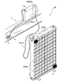
- the plant cultivating apparatus includes a container body 21 that is rectangular and made of synthetic resin, for example.
- the container body 21 has a bottom wall 23 and four side walls 24 mounted upright from four sides of the bottom wall 23 to define a planting space 22 for cultivating the plant P (see Figs. 9 to 11 ).
- the planting space 22 of the container body 21 is sectioned by partition walls 25 extending vertically and comparting walls 26 extending horizontally into numeral planting space units 22a. More particularly, in the current embodiment, the planting space is sectioned into sixteen planting space units 22a by three partition walls 25 and three comparting walls 26.
- the partition walls 25 each have a communicating opening 27 for planting water W (see Fig. 9 and 10 ). Further, four upper walls 28 are continuously formed between the lateral side walls 24 to cover part of the top of the planting space units 22a.
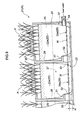
- the bottom wall 23 and side walls 24 of the container body 21 forms a horizontal water-storage portion 29 for storing planting water (rainwater) W, as shown in Fig. 9 .
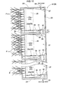
- a vertical posture B of the container body 21 shown in Figs. 7 and 8 in which the planting space 22 is orientated sideways the bottom wall 23, side walls 24, comparting walls 26 and upper walls 28 form a vertical water-storage portion 30 for storing planting water W as shown in Fig. 10 .
- sixteen horizontal water-storage units 29a are formed by the bottom wall 23, side walls 24, partition walls 25, and comparting walls 26 in the horizontal posture A of the container body 21.
- the four horizontal water-storage units 29a arranged in a horizontal direction are communicated with each other through the communicating openings 27.
- sixteen vertical water-storage units 30a are formed by the bottom wall 23, side walls 24, partition walls 25, comparting walls 26, and upper walls 28 in the vertical posture B of the container body 21. More particularly, the four vertical water-storage units 30a arranged at the bottom in Fig. 7 are formed by the bottom wall 23, side walls 24, partition walls 25, and upper walls 28, while the remaining twelve vertical water-storage units 30a are formed by the bottom wall 23, side walls 24, partition walls 25, comparting walls 26, and upper walls 28.
- the four vertical water-storage units 30a arranged in the horizontal direction are communicated with each other through the communicating openings 27.
- Overflow tubular members 31 are provided in the horizontal water-storage portion 29 and the vertical water-storage portion 30 of the container body 21 for maintaining planting water W stored in the water-storage portions 29 and 30 in a constant level or below.
- Each overflow tubular member 31 has one opening end serving as the overflow outlet 32 while the other opening end serving as a drain outlet 33. More particularly, referring to Fig. 7 , the tubular member 31 in this embodiment are provided in the eight planting space units 22a, the four planting space units 22a arranged at the left side and the four planting space units 22a arranged at the right side.
- the overflow outlet 32 in each tubular member 31 has a leading end located at a position remote from the bottom wall 23 of the container body 21 by a predetermined distance "a" toward the upper wall 28 in the horizontal posture A shown in Fig. 9 while located at a position remote from the side wall 24 or the comparting wall 26 of the container body 21 by a predetermined distance "b" toward the interior of each planting space unit 22a in the vertical posture B shown in Fig. 10 .
- the adjacent planting space units 22a are communicated with each other through the overflow outlet 32 and the drain outlet 33 of the tubular member 31.
- Two of the side tubular members 31 arranged at the bottom in Fig. 7 each include the drain outlet 33 that is open to the side wall 24. Further, the side wall 24 opposing to the side wall forming the drain outlets is provided with two feed-water inlets 34. It should be noted that the predetermined distances "a” and "b" may be the same or different from each other.
- the container body 21 When used in a relatively flat surface such as a veranda, for example, the container body 21 is placed in the horizontal posture A as shown in Figs. 6 and 9 to accommodate a planting bed or planting soil on the market within each planting space unit 22a for cultivating the plant P.
- Planting water W may be supplied through the water-supply tube 20 (hose, for example) above the planting space 22 that is open upward, or may be supplied through the feed-water inlet 34 connected to the water-supply tube 20 (hose, for example) as shown in Fig. 9 .
- planting water W is firstly supplied to the right-most four planting space units 22a arranged in the horizontal direction in Fig. 9 since those four units 22a are communicated with each other through the communicating openings 27.
- planting water W substantially reaches the level of "a" measured from the bottom wall 23, it flows out of the overflow outlet 32 of the tubular member 31 through the drain outlet 33 into the adjacent left planting space unit 22a shown in Fig. 9 , and eventually into all the planting space units 22a.
- the leading end of the overflow outlet 32 is remote from the bottom wall 23 by the predetermined distance "a" toward the upper wall 28, which allows planting water W to be maintained substantially in the level of "a” which corresponds to the distance remote from the bottom wall 23 or below in each planting space unit 22a.
- the horizontal water-storage portion 29a is defined by a part at the level of "a” or below.
- planting water W may be supplied through the water-supply tube 20 (hose, for example) to the planting space 22 that is open sideways, or may be supplied through the feed-water inlet 34 connected to the water-supply tube 20 (hose, for example).
- planting water W is firstly supplied to the upper-most four planting space units 22a in Fig. 10 and stored in the vertical water-storage units 30a.
- the vertical water-storage portion 30a is defined by a part at the level of "b” or below.
- the plant cultivating apparatus may be used with the container body 21 being in the horizontal posture A or in the vertical posture B.
- the overflow outlet 32 of the tubular member 31 is used in common in both the postures.
- a plurality of the container bodies 21 may be used in parallel depending on the area of the veranda or the retaining wall in which the container body 21 is placed.
- Fig. 11 One example of such a mode is shown in Fig. 11 .
- six container bodies 21 are arranged in parallel with the planting spaces 22 being oriented in the same direction.
- the overflow outlet 32 of the upper container body 21 is communicated with and connected to the planting space 22 of the lower container body 21 through the drain outlet 33 and the feed-water inlet 34.
- the whole unit is retained by a frame F having support stands F1.
- the container body 21 may be formed by only four of the planting space units 22a arranged vertically in the above-noted mode.
- the plurality of planting space units 22a are arranged vertically in the vertical posture B of the container body 21.
- the adjacent plating space units 22a communicate with each other through the overflow outlet 32 provided in the comparting wall 26 for planting water.
- both the overflow outlets 32 and the feed-water inlets 34 are located in the different positions in the planting space units.
- both the overflow outlets 32 and the feed-water inlets 34 are arranged right and left alternately in the vertical posture B of the container body 21.
- the overflow outlet 32 of the upper container body 21 and the feed-water inlet 34 of the lower container body 21 are aligned.
- Such a construction may be applied to the container body 21 shown in the above-noted mode.
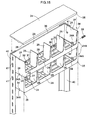
- the half-finished product 21A shown in Fig. 14 is has a structure which is very similar to the arrangement shown Fig. 12 in that only the side wall 24 positioned at the front side of the container body 21 in the plant cultivating apparatus is removed from the container body 21.
- a columnar member 31 A for forming the overflow tubular member 31 and the overflow outlet 32, and a projection 34A forming the feed-water inlet 34 are integrally formed with the half-finished product 21A.
- the side wall 24 provided independently of the half-finished product 21A has stepped portions 35 formed in three sides thereof for engaging the half-finished product 21A.
- An upper edge 36 of the half-finished product 21A shown in Fig. 14 is adapted to be engaged with the stepped portions 35 of the side wall 24 provided independently.
- the lower side walls 24 provided in the half-finished product 21A shown in Fig. 14 each have the same stepped portions 35 formed in three sides thereof as the stepped portion 35 of the side wall 24 provided independently.
- Numeral 37 in the drawings represents a recess for fittingly receiving the projection 34A while numeral 38 in the drawings represents a recessed groove for facilitating the flow of planting water W.
- This half-finished product 21A of the container body is the one-piece molded product made of synthetic resin and thus can be manufactured relatively simply and economically.
- the side wall 24 has such a simple structure that it is manufactured simply and economically by synthetic resin.
- the stepped portions 35 of the side wall 24 are engaged with the upper edge 36 of the half-finished product 21A and joined together by using an adhesive as necessary.
- the columnar member 31A is perforated to form the overflow outlet 32 (see Fig. 15 ).
- the container body 21 for the plant cultivating apparatus as shown in Fig. 12 can be simply manufactured.
- the upper edge 36 of the half-finished product 21A is engaged with the stepped portions 35 of another half-finished product 21A to stack a number of half-finished products 21A serially. Then, the stepped portions 35 of the side wall 24 are engaged with the upper edge 36 of the uppermost half-finished product 21A, thereby providing the plant cultivating apparatus having a desired height.
- the columnar member 31A is perforated to form the overflow outlet 32.
- any of the projections 34A provided in the uppermost half-fuiished product 21A may be perforated in the bottom wall 23 or the upper side wall 24 in Fig. 15 , for example, to form the feed-water inlet 34.
- a hose connecting element 39 may be attached to the feed-water inlet 34 for connecting the feed-water hose to the container body depending on the case. It is also possible to perforate the left-side projection 34A and the projection 34A of the lower half-finished product 21A for use as the feed-water inlet 34 for the laterally adjacent plant cultivating apparatus (not shown). It should be noted that the right-side projection 34A of the projections 34A in the uppermost half-finished product 21A shown in Fig.
- Angled members 40 may be arranged at corners of the stacked numeral half-finished products 21A as necessary.
- the angled members 40 and the half-finished products 21A are connected to each other by suitable connecting elements 41 to reinforce the plant cultivating apparatus per se, which allows those stacked containers to be arranged in the horizontal direction along the retaining wall, for example.
- Fig. 17 schematically shows another plant cultivating system 18 different from that of the first embodiment described above.
- the plant cultivating system 18 comprises the rainwater catchment apparatus 1, the plant cultivating apparatus 16b for cultivating the plant, and the water-supply mechanism 17 for supplying water pumped up by the rainwater catchment apparatus 1 to the plant cultivating apparatus 16b.
- water stored in the water-storage tank 13 of the rainwater catchment apparatus 1 is automatically supplied to the plant cultivating apparatus 16b by the water-supply mechanism 17.
- the plant cultivating system 18 when used in the rooftop of the building, for example, it is possible to arrange the rainwater catchment apparatus 1 and the plant cultivating apparatus in proximity to each other, which can save working energy in the pumping mechanism 6 or the water-supply mechanism 17 of the rainwater catchment apparatus 1.
- the water-supply mechanism 17 and the plant cultivating apparatus 16b in the current embodiment will be described in detail hereinafter.
- the water-supply mechanism 17 includes the water-supply pump 19 for feeding water stored in the water-storage tank 13 to the plant cultivating apparatus 16b, and the water-supply tube 20 (hose, for example) for allowing the water-supply pump 19 to communicate with the plant cultivating apparatus 16b.
- Figs. 18 and 19 show the plant cultivating apparatus 16b in a first using mode ( FIG. 18 shows a front side thereof; Fig. 19 shows a back side thereof).
- the plant cultivating apparatus 16b includes a water-storage tray 52 for storing water to be supplied to the plant P, a plurality of circular retaining portions 53 each for accommodating a cultivating bed 55 for cultivating the plant P, and a cover portion 54 for covering the water-storage tray 52 from above.
- the water-storage tray 52 includes raised bottom portions 52a formed between the retaining portions 53.
- Fig. 20 is a schematic cross section of the plant cultivating apparatus 16b as viewed form a direction of arrow A in Fig. 18 with the cultivating bed 55 being accommodated in one of the retaining portions 53.
- a planting pot or a planter holding proper planting soil therein and having a bore formed in a bottom thereof, or planting soil per se may be used, for example.
- the cultivating bed is not limited to those materials, but any material will do as long as it is accommodated in the retaining portion to allow water to flow thereinto from a bottom portion thereof so that the roots of the plant can absorb water flowed into the material.
- any solid culture medium for cultivating the plant may be used, including natural planting soil such as red-ball soil, weathered yellowish volcanic soil ( kanuma soil), leaf soil, peat or bog moss, or various kinds of resin foam such as vermiculite, pearlite, urethane resin or phenol resin, or artificial planting soil such as rock wool or hydroponic balls, for example.
- the shape of the culture medium is not limited to the one illustrated, but may be desirably selected from various forms such as block, sands, pellets or lumps, for example. When the culture medium made of sands, pellets or lumps is used, they may be put into a net-like bag, for example, in use so as not to leak to the outside.
- the water-storage tray 52 further includes two connecting nozzles (connecting portions) 56 for allowing the adjacent water-storage trays 52 to communicate with each other.
- the connecting nozzles 56 are distinguished from each other depending on the flowing direction of water.
- One of the connecting nozzles acts as a flow-in connecting nozzle (flow-in connecting portion) 56a while the other of the connecting nozzles as a flow-out connecting nozzle (flow-out connecting portion) 56b.
- the flow-in connecting nozzle 56a may be removably connected to the flow-out connecting nozzle 56b of the adjacent water-storage tray 52 through a connecting hose 66 so that water flows from the water-storage tray 52 to the adjacent water-storage tray 52 through the connection hose 66.
- the flow-in connecting nozzle 56a of the water-storage tray 52 may be connected to the flow-out connecting nozzle 56b of the adjacent water-storage tray 52 through the connecting hose 66 successively, which allows the number of water-storage trays 52 desired to be communicated and connected with each other. In this way, water is supplied to all of the plural water-storage trays 52 that are communicated and connected with each other.
- FIG. 20 Shows the flowing direction of water.
- Water flowing from the flow-in connecting nozzle 56a is temporarily retained in a water-storage space 58 within the water-storage tray 52.
- the water-storage space 58 represents a maximum space for storing water that is defined between the lowest position of an inner peripheral surface of the connecting nozzle 56 and a bottom surface of the water-storage tray 52.
- the retaining portion 53 has a bottom portion 53a provided with a through-bore 57 (feed-water portion) to communicate with the water-storage space 58.
- the bottom portion 53a is located at a level "t" lower than the lowest level of the inner peripheral surface of the connecting nozzle 56 (that is, a maximum level T standing water 59 as filling up the water-storage space 58). Therefore, when water is caused to overflow the water-storage space 58, standing water 59 wells up into the retaining portion 53 through the through-bore 57, and water is constantly maintained in the retaining portion 53 at a level achieved by deducting the level "t" of the bottom portion 53a from the level T of standing water 59.
- the depth of the water-storage space 58 or the depth or width of the retaining portion 53 may vary to adjust the amount of water to be supplied to the retaining portion 53, thereby supplying (watering) a proper amount of water at all times depending on the cultivating condition (the kind of plant, for example).
- a ventilation hole 74 is formed in a top surface of the cover portion 54 near the flow-out connecting nozzle 56b for allowing the water-storage space 58 to communicate with the outside. Air accumulated in the water-storage space 58 is discharged through the ventilation hole 74. This prevents standing water 59 from overflowing and flowing out to the flow-out connecting nozzle 56b less smoothly due to air accumulation, which makes it easy to supply water to all the water-storage trays 52 appropriately when the plurality of water-storage trays 52 are communicated and connected with each other.
- a plurality of the plant cultivating apparatuses 16b may be interconnected and arranged depending on the site of the building or the area of the rooftop to be greened.
- Such assembly of the plant cultivating apparatuses 16b includes one flow-in connecting nozzle 56a and one flow-out connecting nozzle 56b which remain unconnected and open.
- the water-supply tube 20 hose, for example
- the water-storage trays 52 of the plant cultivating apparatuses 16b overflow successively, whereby water is supplied to all the plant cultivating apparatuses 16b eventually.
- the open flow-out connecting nozzle 56b may be connected to a proper pipe or fluid passage to discharge water. It is also possible to connect the open flow-in connecting nozzle 56a to the open flow-out connecting nozzle 56b through a hose or the like to circulate water through a pump while supplying a proper amount of water additionally from the outside.
- the plant cultivating apparatus 16b may be manufactured by the known molding techniques (including injection molding or blow molding, preferably by blow molding) using thermoplastic resin such as polypropylene resin, polyethylene resin or polyethylene terephthalate (PET).
- thermoplastic resin such as polypropylene resin, polyethylene resin or polyethylene terephthalate (PET).
- Figs. 21 to 26 show the plant cultivating apparatus 16b in a second using mode.
- the plant cultivating apparatus 16b in the second using mode includes the water-storage tray 52 for storing water to be supplied to the plant, and a one-piece molded plant cultivating container 64 (molded product having a plurality of retaining portions 53 for containing the cultivating bed 55 for cultivating the plant P that are integrally formed with the cover portion 54 for covering the water-storage tray 52 from above).
- the water-storage tray 52 and the plant cultivating container 64 are separably fitted to each other.
- Fig. 22 schematically shows a section of the plant cultivating apparatus 16b in the second using mode with the cultivating bed 55 being accommodated within one of the retaining portions 53 (where the water-storage tray 52 is fitted to the plant cultivating container 64) taken along arrow B-B in Fig. 21 .
- the water-storage tray 52 of the plant cultivating apparatus 16b in the second using mode includes the two connecting nozzles (connecting portions) 56 for allowing the adjacent water-storage trays 52 to communicate with each other.
- the connecting nozzles 56 are distinguished from each other depending on the flowing direction of water.
- One of the connecting nozzles acts as the flow-in connecting nozzle (flow-in connecting portion) 56a while the other of the connecting nozzles as the flow-out connecting nozzle (flow-out connecting portion) 56b.
- the water-storage tray 52 of the second using mode is provided with a receiving portion 60 on which the plant cultivating container 64 is placed.
- the receiving portion 60 has a well-up opening 60a. Water flowing through the flow-in connecting nozzle 56a wells up through the opening 60a to flow over the receiving portion 60 and is stored in the water-storage space 58 as in the similar way to the first using mode.
- the retaining portion 53 has the bottom portion 53a provided with the through-bore 57 (feed-water portion) to communicate with the water-storage space 58.
- the bottom portion 53a is located at a level "t" lower than the lowest level of the inner peripheral surface of the connecting nozzle 56 (that is, a maximum level T of standing water 59 as filling up the water-storage space 58).
- the ventilation hole 74 is formed in the top surface of the water-storage tray 52 near the flow-out connecting nozzle 56b.
- the water-storage space 58 when water is caused to overflow the water-storage space 58, standing water 59 that has welled up through the well-up opening 60a and flowed out to the receiving portion 60 wells up into the retaining portion 53 through the through-bore 57, and water is constantly maintained in the retaining portion 53 at a level achieved by deducting the level "t" of the bottom portion 53a from the level T of standing water 59.
- the depth of the water-storage space 58, the height of the receiving portion 60, or the depth or width of the retaining portion 53 may vary to adjust the amount of water to be supplied to the retaining portion 53, thereby supplying (watering) a proper amount of water at all times depending on the cultivating condition (the kind of plant, for example).
- the plant cultivating container 64 has the bottom portion folded up from the lower side to the upper side at an outer side portion thereof to form a double-wall portion 75, which provides a raised bottom in a central portion thereof to have a recessed shape opened downward.
- the water-storage tray 52 is placed within the space surrounded by the double-wall portion 75 to be covered entirely with the plant cultivating container 64.
- a shading effect can be achieved by the plant cultivating container 64 in the entire water-storage space 58, thereby effectively preventing growth of algae and the like in standing water 59.
- the water-storage tray 52 has a first fitting portion 76 while the plant cultivating container 64 has a second fitting portion 77.
- the first fitting portion 76 is provided at an upper side portion of outer peripheries of the water-storage tray 52 to project outward.
- a projection 77a is provided to project inward from the double-wall portion 75 of the plant cultivating container 64.
- a recessed portion formed in an upper part of the double-wall portion 75 defined above the projection 77a serves as the second fitting portion 77.
- the first fitting portion 76 and the second fitting portion 77 are fitted together to attach the plant cultivating container 64 to the water-storage tray 52.
- the projection 77a in the second fitting portion 77 is provided in the double-wall portion 75 of the plant cultivating container 64, which means that the second fitting portion 77 is provided in a portion that has an increased strength in the plant cultivating container 64.
- the first fitting portion 76 is less easily disengaged from the second fitting portion 77, which allows the plant cultivating container 64 to be readily and properly attached to the water-storage tray 52.
- the plant cultivating container 64 has the hollow interior and an opening 78 is provided for allowing the interior space to communicate with the outside.
- the opening 78 is closed with a removable lid member 79. With the lid member 79 being removed, water or sand is put into the interior space of the plant cultivating container 64 from the opening 78.
- the plant cultivating container 64 with the lid member 79 being attached can be used as a weight. Thus, when placed on the rooftop, the plant cultivating container 64 can be restrained from being moved or toppling over when the wind blows, for example. On the other hand, the plant cultivating container 64 can be easily carried when the lid member 79 is removed to discharge water or sand that has been put into the container through the opening 78.
- a float portion 63 portion within which air is confined
- the floating force provided by the plant cultivating container 64 is adjusted so that the bottom portion 53a of the retaining portion 53 is positioned lower than the surface 65 of the water with the cultivating bed 55 being accommodated in the retaining portion 53.
- the floating force may be adjusted to adjust the amount of water to be supplied to the retaining portion 53.
- the plant cultivating container 64 is constructed as the one-piece molded product having the retaining portion 53 and the float portion 63.
- the float portion 63 is adapted to allow the plant cultivating container 64 to float such that the bottom portion 53a of the retaining portion 53 is positioned lower than the surface 65 of the water such as the pond, river, lake, etc. More particularly, the float 63 is formed in the plant cultivating container 64 by filling the interior space of the hollow plant cultivating container 64 with air and closing the opening 78 with the lid member 79.
- the plant cultivating container 64 forms the raised bottom at the central portion thereof having the retaining portion 53 to provide the recessed part opened downward.
- the plant cultivating container 64 includes a body having an edge portion positioned lower than the bottom portion 53a of the retaining portion 53.
- the float portion 63 is formed in a peripheral portion of the retaining portion 53 to extend to the position lower than the bottom portion 53a of the retaining portion 53.
- the floating force applied by the float portion 63 is increased to prevent the bottom portion 53a of the retaining portion 53 from being positioned too lower than the surface 65 of the water such as the pond, river, lake, etc.
- the surface 65 of the water such as the pond, river, lake, etc.
- the plant cultivating container 64 is provided with a connecting portion 61 for connecting to the adjacent plant cultivating container 64.
- the connecting portion 61 has a hole 61a.
- the connecting portions 61 in the adjacent plant cultivating containers 64 are placed with one above the other to align their holes 61 a.
- a proper connecting element 62 (bolt, for example) that can extend through the aligned holes 61 a is fitted to fix the holes together.
- the connecting portions 61 are provided in the cover portion 54 and arranged in central portions in the four sides of the plant cultivating container 64 that has a rectangular shape as viewed from the top. As shown in Fig. 23 , the connecting portion 61 provided at one side of the container is arranged at a vertical position different from that of the connecting portion 61 provided at the other side of the container, whereby the connecting portions 61 of the respective plant cultivating containers 64 that are adjacent to each other in the transverse direction (horizontal direction) are placed one above the other to join those plant cultivating containers 64 together. When the plant cultivating containers 64 that are adjacent to each other in the transverse direction (horizontal direction) are joined together, one of the connecting portions 61 that is located at the one side (upper side in Fig.
- Each connecting portion 61 is provided to extend horizontally in a portion recessed inward from the outer side of the plant cultivating container 64.
- the connecting portions 61 of those plant cultivating containers 64 are placed one above the other to bring the container bodies of the respective plant cultivating containers 64 into contact with each other.
- the floating forces applied by the float portions 63 provided in the plurality of plant cultivating containers 64 can be combined to float the plurality of plant cultivating containers 64 integrally or as a unit assembly.
- either a top surface or bottom surface of the connecting portion 61 provided at the one side of the container body of the plant cultivating container 64 has generally the same height as either a bottom surface or top surface of the connecting portion 61 provided at the other side.
- Figs. 24 to 26 show another mode of the second using mode. More particularly, as shown in Fig. 24 , the plant cultivating container 64 in this mode includes the retaining portion 53 having a greater width and a plurality of (three in Fig. 24 , which is not limitative) through-bores 57 formed in the bottom portion 53a thereof. (It should be noted that, in the plant cultivating container 64 shown in Fig. 21 , each retaining portion 53 has one through-bore 57.)
- Fig. 25 schematically shows a section of the plant cultivating apparatus 16b in accordance with the second using mode (where the water-storage tray 52 is fitted to the plant cultivating container 64) taken along arrow C-C in Fig. 24 . As shown in Fig.
- the water-storage tray 52 has the raised bottom portion 52a to form the minimum necessary water-storage space 58, thereby saving water to be used.
- the removable lid member 79 is provided in the opening 78 of the plant cultivating container 64 to close the opening 78.
- the water-storage tray 52 is provided with the first fitting portion 76 while the plant cultivating container 64 with the second fitting portion 77.
- the arrangements and the shapes of those fitting portions are different from those shown in Figs. 21 to 23 . More particularly, as shown in Fig.
- the first fitting portions 76 are formed as projections extending upward from the top surface of the water-storage tray 52 at opposite end portions and a central portion thereof in the horizontal direction.
- the second fitting portions 77 are formed as recesses representing raised bottom portions of the bottom surface of the plant cultivating container 64 at opposite end portions and a central portion thereof in the horizontal direction.
- the plant cultivating container 64 is placed on the water-storage tray 52 such that the convex first fitting portion 76 and the concave second fitting portion 77 are fitted together, thereby attaching the plant cultivating container 64 to the water-storage tray 52.
- Fig. 26 shows that the plant cultivating container 64 shown in Figs.
- the float portion 63 is provided so that the bottom portion 53a of the retaining portion 53 is positioned lower than the surface 65 of the water to allow the plant cultivating container 64 to float.
- the plant cultivating container 64 is provided with the connecting portion 61 to connect to the adjacent plant cultivating container 64 in the horizontal direction.
- Fig. 27 shows the plant cultivating apparatus 16b as shown in Figs. 24 to 26 in another mode. More particularly, as shown in Fig. 27 , the well-up opening 60a formed in the water-storage tray 52 is located in a horizontal position different from that of the through-bore 57 formed in the bottom portion 53a of the retaining portion 53, with the plant cultivating container 64 being attached to the water-storage tray 52. (In Figs.
- the well-up opening 60a formed in the water-storage tray 52 is located in the horizontal position same as that of the through-bore 57 formed in the bottom portion 53a of the retaining portion 53,with the plant cultivating container 64 being attached to the water-storage tray 52.)
- Such an arrangement in which the well-up opening 60a is located in the horizontal position different from that of the through-bore 57 prevents the roots of the plant P from entering the water-storage space 58 through the well-up opening 60a even if they pass through the through-bore 57. As a result, it is prevented that the flow of standing water 59 is hampered by resistance of the roots of the plant P in the water-storage space 58.
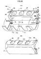
- Figs. 28(A), 28(B) and 29 show the plant cultivating apparatus 16b in a third using mode.
- the plant cultivating apparatus 16b includes the water-storage tray 52 for storing water to be supplied to the plant P, a plurality of the circular retaining portions 53 for housing the cultivating bed for planting the plant therein, and the cover portion 54 for covering the water-storage tray 52 from above.
- the water-storage tray 52 further includes two connecting nozzles (connecting portions) 56 for allowing the adjacent water-storage trays 52 to communicate with each other.
- the connecting nozzles 56 are distinguished from each other depending on the flowing direction of water.
- the water-storage tray 52 is provided with an attaching portion 67 (attaching projection 67a and attaching recess 67b).
- the attaching projection 67a is engageable with a main body-metal fitting 69 that is attached to a wall surface 68 in advance.
- the attaching recess 67b is engageable with a protection cover-metal fitting 70 that is also attached to the wall surface 68 in advance.
- the plant cultivating apparatus 16b of the third using mode can be installed in the wall surface 68 by bringing the attaching projection 67a and the attaching recess 67b into engagement with the main body-metal fitting 69 and the protection cover-metal fitting 70, respectively, as shown in Fig. 28(A) .
- Both the main body-metal fitting 69 and the attaching projection 67a include bolt bores 73 for receiving bolts.
- the attaching projection 67a is attached to the main body-metal fitting 69, with the bolt bores 73 being aligned.
- a protection cover member 71 (made of stainless steel or FRP (fiber reinforced plastic), for example) is hinged to the protection cover-metal fitting 70 to be swingable vertically.
- the protection cover member 71 has a plurality of openings 71 a and a plurality of hooking portions 71b. As shown in Fig.
- the attaching portion 67 is engaged with the main body-metal fitting 69 and the protection cover-metal fitting 70, and then the protection cover member 71 is lifted upward to cover the plant cultivating apparatus 16b thereby to bring the hooking portions 71b to be hooked to a stepped portion (hooked portion 72) provided in the top surface of the plant cultivating apparatus 16b for fixing.
- the position and size of each opening 71a of the protection cover member 71 are adapted to the position and size of each retaining portion 53 so as not to cover the retaining portion 53.
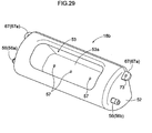
- the plant cultivating apparatus 16b in this mode includes the retaining portion 53 having a greater width and a plurality of (three in Fig. 29 , which is not limitative) through-bores 57 formed in the bottom portion 53a thereof. (It should be noted that, in the plant cultivating apparatus 16b shown in Fig. 28 , one through-bore 57 is provided for each retaining portion 53.)
- the plant cultivating apparatus 16b There is no limitation, in particular, in the shape (circular, quadrangular, hexagonal, etc.) of the plant cultivating apparatus 16b noted above and in the shape and the number of the retaining portions provided within the plant cultivating apparatus 16b. Any desired arrangement can be employed as necessary.
- the plurality of plant cultivating apparatuses 16b are joined together through the connecting hoses. Instead, the connecting nozzles may be directly connected together.
- the position and the number of the connecting nozzles (connecting portions) provided in the plant cultivating apparatus 16b are not limited to those of the foregoing using modes, but may be desirably selected as long as they serve to supply and discharge water properly by action of overflow.
- Fig. 30 schematically shows the plant cultivating system 18 further comprising a rainwater collection control member 80 and a tap water-supply portion 90, for example.
- the plant cultivating system 18 comprises the rainwater catchment apparatus 1, the plant cultivating apparatus for cultivating the plant (which corresponds to the container body 21 in the first embodiment or the plant cultivating apparatus 16b in the second embodiment), and the water-supply mechanism 17 (water-supply tube 20) for supplying water pumped up by the rainwater catchment apparatus 1 to the plant cultivating apparatus.
- the reservoir 5 of the rainwater catchment apparatus 1 is provided with a mounting portion 86 at an upper part thereof for attaching the rainwater collection control member 80 thereto.
- the mounting portion 86 includes an opening edge 87 (see Fig. 31(B) ) on which the rainwater collection control member 80 is placed, a plurality of rainwater inlets 7 for introducing rainwater into the water-storage portion 8 of the reservoir 5, and a cut-away portion 89 for receiving a power cable or the like.
- the rainwater collection control member 80 includes a first level sensor 81, second level sensor 82, third level sensor 83 and fourth level sensor 84.
- the first level sensor 81, second level sensor 82 and third level sensor 83 are inserted through an opening 88 of the mounting portion 86 to place a main body of the rainwater collection control member 80 on the opening edge 87.
- the rainwater collection control member 80 is adapted to detect the level of water stored in the reservoir 5 by the first level sensor 81, second level sensor 82 and third level sensor 83 and to detect the level of water stored in the water-storage tank 13 by the fourth level sensor 84.
- the rainwater collection control member 80 is adapted to give a command to the draw-up pump 12 through wiring 85 to activate the draw-up pump 12 and perform control to pump up water stored in the reservoir 5 to the water-storage tank 13 when the level of water stored in the reservoir 5 reaches a level L1 detected by the first level sensor 81 or above, while stopping the draw-up pump 12 when the level of water is lower than a level L2 detected by the second level sensor 82.
- the rainwater collection control member 80 is adapted to detect the level of water stored in the water-storage tank 13 by the fourth level sensor 84, and stop the draw-up pump 12 quickly when the water-storage tank 13 is filled up and the fourth level sensor 84 detects that the level of water in the water-storage tank 13 reaches a level L3 (see Fig. 30 ).
- the water-storage tank 13 in the plant cultivating system 18 in accordance with the current embodiment is provided with the tap water-supply portion 90.
- the tap water-supply portion 90 includes a water pipe 91 through which water flows, a faucet 92 for supplying tap water, and an arm portion 93 pivotably connected to the water pipe 91, for example.
- the arm portion 93 includes a valve 95 that is vertically movable through a valve mounting bore 94 to open and close the water pipe 91, and a float member 96 exerting a floating force. As shown in Fig.
- the water pipe 91 for supplying tap water is inserted into the water-storage tank 13 through a water pipe mounting bore 97 formed in a side face of the water-storage tank 13, whereby tap water is supplied to the water-storage tank 13 through the faucet 92.
- the float member 96 attached to the arm portion 93 floats in the water-storage tank 13 to be movable vertically in accordance with the water level in the water-storage tank 13.
- the valve 95 is interlocked with vertical movement of the float member 96 by the arm portion 93 to move vertically to open or close the water pipe 91. More particularly, as shown in Fig. 32(A) , when the water level in the water-storage tank 13 becomes lower than the level L4, the float member 96 is moved to a position lower than the level L4. With this, the valve 95 is also moved downward through the arm portion 93 to open the water pipe 91, as a result of which tap water is supplied from the faucet 92. On the other hand, as shown in Fig.
- the float member 96 when tap water or rainwater is supplied to cause the water level in the water-storage tank 13 to reach the level L4 or above, the float member 96 is moved upward by its floating force. With this, the valve 96 is moved upward through the arm portion 93 to close the water pipe 91, as a result of which supply of tap water is stopped.
- the rainwater collection control member 80 and the tap water-supply portion 90 serve to maintain the level of water to be stored in the water-storage tank 13 between the level L3 and the level L4 at all times.
- the water-storage tank 13 is positioned higher than the plant cultivating apparatus while the water-supply tube 20 attached to the water-storage tank 13 is lower than the level L4.
- the feed-water valve 98 mounted on the water-supply tube 20 is opened, water stored in the water-storage tank 13 is supplied to the plant cultivating apparatus 16b or 21 by the difference in potential energy.
- the plant cultivating system 18 in accordance with the current embodiment allows water-supply to the plant to be completely automated by using both rainwater and tap water.
- power for the rainwater collection control member 80 and the draw-up pump 12 may be supplied from a solar power generation system installed on the rooftop of the building framework, for example.
- the rainwater catchment apparatus in accordance with the present invention is usable in the plant cultivating system in combination with the plant cultivating apparatus in order to use collected water in plant cultivation, for example.
Landscapes
- Engineering & Computer Science (AREA)
- Life Sciences & Earth Sciences (AREA)
- Water Supply & Treatment (AREA)
- Environmental Sciences (AREA)
- Architecture (AREA)
- Civil Engineering (AREA)
- Structural Engineering (AREA)
- Soil Sciences (AREA)
- Environmental & Geological Engineering (AREA)
- Health & Medical Sciences (AREA)
- Hydrology & Water Resources (AREA)
- Public Health (AREA)
- Cultivation Receptacles Or Flower-Pots, Or Pots For Seedlings (AREA)
Abstract
Description
- The present invention relates to a rainwater catchment apparatus comprising a reservoir for storing rainwater flowing into a rainwater outlet formed in a building framework, and a pumping mechanism for pumping water stored in the reservoir.
- The above-noted rainwater catchment apparatus is adapted to efficiently collect rainwater falling on a roof or rooftop of the building framework (a residential house or building, for example). Rainwater collected can be used in various ways (for watering on a plant or flushing in a toilet, for example).
As the conventional art relating to such a rainwater catchment apparatus,Patent Document 1 has proposed water catchment equipment having the reservoir for collecting rainwater that is provided in the front of the house or building, for example.
[Patent Document 1] Japanese Patent Publication No.56-38733 - When the conventional rainwater catchment apparatus noted above is mounted on an existing building, the water catchment equipment is provided in the front of the building, and thus a new drainage pipe needs to be prepared to transport rainwater from the rainwater outlet to the water catchment equipment, which requires renovation of the building.
On the other hand, when the above-noted rainwater catchment apparatus is mounted on a new-built building, it is required to design the building to adapt the rainwater catchment apparatus to the building, which disadvantageously affects the efficiency in construction of the building.
The present invention has been made having regard to the above-noted circumstances, and the object of the invention is to provide a rainwater catchment apparatus that can be easily mounted without renovating the building. - A first characteristic feature of the present invention lies in a rainwater catchment apparatus comprising:
- a rainwater inlet for introducing rainwater;
- a flange portion engaged with a peripheral portion of a rainwater outlet serving as a leading end of a drainage canal formed in a building framework for introducing rainwater into the rainwater inlet;
- a drain portion for discharging excessive water exceeding a predetermined level to the drainage canal;
- a reservoir freely fitted into the drainage canal through the rainwater outlet; and
- a pumping mechanism for pumping water stored in the reservoir to the outside.
- The rainwater catchment apparatus of the present invention can be easily mounted on the existing rainwater outlet of the building without renovating the building.
More particularly, in installing the rainwater catchment apparatus of the present invention, it is only required that the reservoir be fitted into the rainwater outlet to engage the flange portion with the peripheral portion of the rainwater outlet.
Rainwater flowing into the rainwater outlet flows over the flange portion into the rainwater inlet and is stored in the reservoir. The stored rainwater is pumped by the pumping mechanism of the present invention to be used in various ways (watering on a plant or flushing in a toilet, for example).
According to the present invention, even if a large amount of water flows into the reservoir due to heavy rain, excessive water exceeding a predetermined level of the reservoir is discharged from the drain portion to the drainage canal. Thus, there is no concern that water would overflow the rainwater outlet of the building to flood the rooftop or the like. - A second characteristic feature of the present invention lies in that the pumping mechanism includes a draw-up pump for pumping water stored in the reservoir, and a pumping tube through which water flows pumped by the draw-up pump.
- Since the pumping mechanism in the rainwater catchment apparatus of the present invention includes a draw-up pump for pumping water stored in the reservoir, and a pumping tube through which water flows pumped by the draw-up pump, water stored in the reservoir is efficiently pumped and is used more easily.
- A third characteristic feature of the present invention lies in that the rainwater inlet is provided with a filter portion for removing solid substances contained in rainwater.
- According to the rainwater catchment apparatus of the present invention, the rainwater inlet is provided with a filter portion for removing solid substances contained in rainwater, which prevents a capacity of the reservoir from being reduced, or prevents water to be stored from being reduced, by accumulation of solid substances. Moreover, more cleaned water with solid substance being removed can be used.
- The characteristic feature of a plant cultivating system in accordance with the present invention lies in comprising:
- the rainwater catchment apparatus;
- a plant cultivating apparatus; and
- a water-supply mechanism for supplying water pumped by the rainwater catchment apparatus to the plant cultivating apparatus.
- With the plant cultivating system of the present invention, a watering operation is simplified to cultivate the plant efficiently.
-
-
Fig. 1 is a perspective view schematically showing a condition in which a rainwater catchment apparatus of the present invention is provided in a rainwater outlet formed in a building framework; -
Fig. 2 is a sectional view schematically showing the condition in which the rainwater catchment apparatus of the present invention is provided in the rainwater outlet formed in the building framework; -
Fig. 3 is a perspective view of a reservoir in the rainwater catchment apparatus of the present invention; -
Fig. 4 is a sectional view schematically showing the condition in which the rainwater catchment apparatus of the present invention (modified mode) is provided in the rainwater outlet formed in the building framework; -
Fig. 5 schematically shows a plant cultivating system comprising the rainwater catchment apparatus of the present invention in combination with a plant cultivating apparatus; -
Fig. 6 is a perspective view of the plant cultivating apparatus in a horizontal posture; -
Fig. 7 is a partially cut-away front view of the plant cultivating apparatus in a vertical posture; -
Fig. 8 is a sectional view taken on line III-III inFig. 2 ; -
Fig. 9 is a sectional view of a principal portion of the plant cultivating apparatus in the horizontal posture; -
Fig. 10 a sectional view of the principal portion of the plant cultivating apparatus in the vertical posture; -
Fig. 11 is a perspective view of the plant cultivating apparatus in the vertical posture; -
Fig. 12 is a perspective view of the plant cultivating apparatus in the horizontal posture in accordance with another mode; -
Fig. 13 is a perspective view of the plant cultivating apparatus in the horizontal posture in accordance with the another mode; -
Fig. 14 is an exploded perspective view of the plant cultivating apparatus in accordance with the another mode; -
Fig. 15 is a perspective view showing a process of assembling the plant cultivating apparatus in accordance with the another mode; -
Fig. 16 is a perspective view of an assembly of the plant cultivating apparatus in accordance with the another mode; -
Fig. 17 schematically shows another plant cultivating system comprising the rainwater catchment apparatus of the present invention in combination with a plant cultivating apparatus; -
Fig. 18 is a perspective view showing an external appearance of a front side of the plant cultivating apparatus (first using mode); -
Fig. 19 is a perspective view showing an external appearance of a back side of the plant cultivating apparatus (first using mode); -
Fig. 20 is a sectional view of the plant cultivating apparatus (first using mode); -
Fig. 21 is a perspective view showing an external appearance of the plant cultivating apparatus (second using mode); -
Fig. 22 is a sectional view of the plant cultivating apparatus (second using mode); -
Fig. 23 is a sectional view of the plant cultivating apparatus (second using mode); -
Fig. 24 is a perspective view showing an external appearance of the plant cultivating apparatus (second using mode); -
Fig. 25 is a sectional view of the plant cultivating apparatus (another mode of the second using mode); -
Fig. 26 is a sectional view of the plant cultivating container; -
Fig. 27 is a sectional view of the plant cultivating apparatus (further mode of the second using mode); -
Fig. 28 is a perspective view showing an external appearance of the plant cultivating apparatus (third using mode); -
Fig. 29 is a perspective view showing an external appearance of the plant cultivating apparatus (another mode of the third using mode); -
Fig. 30 schematically shows a further plant cultivating system comprising the rainwater catchment apparatus of the present invention in combination with a plant cultivating apparatus; -
Fig. 31(A) is a side view of the reservoir and a mounting portion; -
Fig. 31(B) is a top plan view of the reservoir and the mounting portion; and -
Fig. 32 is an enlarged view of a principal portion of a water-storage tank. - Embodiments of the present invention will be set forth hereinafter in reference to the accompanying drawings.
-
-
Figs. 1 and2 each schematically show a condition in which arainwater catchment apparatus 1 is provided in a rooftop of abuilding framework 2 such as a residential house or a building (Fig. 1 is a perspective view;Fig. 2 is a sectional view). Arrows shown in broken line inFigs. 1 and2 indicate a flowing direction of rainwater. -
Fig. 3 is a perspective view of areservoir 5 in therainwater catchment apparatus 1 of the present invention. - As shown in
Figs. 1 to 3 , thereservoir 5 includes arainwater inlet 7 for introducing rainwater, a water-storage portion 8 for storing rainwater introduced, adrain portion 9 for draining off excessive water exceeding a predetermined level to thedrainage canal 4 by overflow, and aflange portion 10 engaged with a peripheral edge of therainwater outlet 3 for introducing rainwater into therainwater inlet 7. Thereservoir 5 is fitted into thedrainage canal 4 through therainwater outlet 3.
In the current mode, afilter portion 11 is provided in therainwater inlet 7 for removing solid substances contained in rainwater. The filter portion, however, is not intended to limit the construction of the present invention, but may be provided as necessary.
It also should be noted that water to be stored in thereservoir 5 is not limited to rainwater, and any water having a chance to flow into therainwater outlet 3 may be included. - A pumping mechanism of the present invention is not limited to any particular construction as long as it is capable of pumping water stored in the reservoir. Typically, the pumping mechanism may include a draw-up pump for pumping water stored in the reservoir and a pumping tube through which water pumped by the draw-up pump flows.
As shown inFig. 1 and2 , thepumping mechanism 6 in the current mode includes a draw-uppump 12 for pumping water stored in the water-storage portion 8, a water-storage tank 13 provided on the roof or rooftop of thebuilding framework 2, and a pumpingtube 14 allowing the draw-uppump 12 to communicate with the water-storage tank 13.
When it rains, rainwater flowing into therainwater outlet 3 flows over theflange portion 10 and enters therainwater inlet 7 to be stored in the water-storage portion 8. Rainwater stored in the water-storage portion 8 is pumped by the draw-uppump 12 to the water-storage tank 13 through the pumpingtube 14 for storage. Rainwater stored in the water-storage tank 13 can be used in various ways (for watering on a plant or flushing in a toilet, for example). - Next, the outline of the way of installing the
rainwater catchment apparatus 1 will be described hereinafter.
In order to install therainwater catchment apparatus 1 in thebuilding framework 2, thereservoir 5 is firstly fitted into therainwater outlet 3 acting as the leading end of thedrainage canal 4 to engage theflange portion 10 with the peripheral edge of therainwater outlet 3. In this, the water-storage portion 8 of thereservoir 5 is disposed within thedrainage canal 4.
Then, thefilter portion 11 is attached to therainwater inlet 7.
Finally, the draw-up pump 12 (the pumpingtube 14 is attached to the draw-uppump 12 for communicating with the water-storage tank 13) is inserted through aninsert inlet 15 formed in thefilter portion 11 to be placed in a bottom portion of thereservoir 5. -
Fig. 4 is a sectional view schematically showing therainwater catchment apparatus 1 in accordance with a modified mode of the present invention. It should be noted that the components having like functions are assigned the like reference numbers to omit repetitious explanation thereof and only the aspects that defer from the above-noted mode will be explained.
As shown inFig. 4 , thereservoir 5 in the current mode includes an innertubular portion 5a formed in the interior thereof. The water-storage portion 8 is disposed between the innertubular portion 5a and an outertubular portion 5b while thedrain portion 9 is disposed in the innertubular portion 5a.
Further, according to the current mode, excessive water exceeding the predetermined level of thereservoir 5 overflows thedrain portion 9 to be discharged to thedrainage canal 4 through the innertubular portion 5a. -
- 1. Various sensors (a level sensor, for example) may be provided within the reservoir in the rainwater catchment apparatus of the present invention.
- 2. The reservoir in the rainwater catchment apparatus of the present invention may be bellows-shaped. Such a reservoir may be easily attachable when the drainage canal disposed within the outlet is a bent pipe.
- Embodiments of a
rainwater catchment apparatus 1 of the present invention will be described hereinafter.
Water collected by therainwater catchment apparatus 1 of the present invention may be used in plant cultivation, for example, (that is to say, used in watering). A combination of therainwater catchment apparatus 1 of the present invention and an appropriate plant cultivating apparatus easily forms a plant cultivating system which may simplify a watering operation to cultivate a plant effectively. -
Fig. 5 schematically shows aplant cultivating system 18 comprising arainwater catchment apparatus 1 of the present invention in combination with a plant cultivating apparatus.
Theplant cultivating system 18 comprises therainwater catchment apparatus 1, the plant cultivating apparatus for cultivating the plant, and a water-supply mechanism 17 for supplying water pumped by therainwater catchment apparatus 1 to the plant cultivating apparatus.
In theplant cultivating system 18, water stored in the water-storage tank 13 of therainwater catchment apparatus 1 is automatically supplied to the plant cultivating apparatus through the water-supply mechanism 17.
In particular, when theplant cultivating system 18 is used in a rooftop of a building, for example, it is possible to arrange therainwater catchment apparatus 1 and the plant cultivating apparatus in proximity to each other, which can save working energy in thepumping mechanism 6 or the water-supply mechanism 17 of therainwater catchment apparatus 1. - The water-
supply mechanism 17 and the plant cultivating apparatus in the current embodiment will be described in detail hereinafter. - The water-
supply mechanism 17 includes a water-supply pump 19 for feeding water stored in the water-storage tank 13 to the plant cultivating apparatus, and a water-supply tube 20 (hose, for example) for allowing the water-supply pump 19 to communicate with the plant cultivating apparatus. - As shown in
Figs. 6 to 8 , the plant cultivating apparatus includes acontainer body 21 that is rectangular and made of synthetic resin, for example. Thecontainer body 21 has abottom wall 23 and fourside walls 24 mounted upright from four sides of thebottom wall 23 to define aplanting space 22 for cultivating the plant P (seeFigs. 9 to 11 ). - Referring to
Fig. 7 , theplanting space 22 of thecontainer body 21 is sectioned bypartition walls 25 extending vertically andcomparting walls 26 extending horizontally into numeralplanting space units 22a. More particularly, in the current embodiment, the planting space is sectioned into sixteenplanting space units 22a by threepartition walls 25 and threecomparting walls 26. Thepartition walls 25 each have a communicatingopening 27 for planting water W (seeFig. 9 and10 ). Further, fourupper walls 28 are continuously formed between thelateral side walls 24 to cover part of the top of theplanting space units 22a. - In a horizontal posture A of the
container body 21 shown inFig. 6 in which theplanting space 22 is oriented upward, thebottom wall 23 andside walls 24 of thecontainer body 21 forms a horizontal water-storage portion 29 for storing planting water (rainwater) W, as shown inFig. 9 . In a vertical posture B of thecontainer body 21 shown inFigs. 7 and8 in which theplanting space 22 is orientated sideways, thebottom wall 23,side walls 24, compartingwalls 26 andupper walls 28 form a vertical water-storage portion 30 for storing planting water W as shown inFig. 10 .
In the current embodiment, sixteen horizontal water-storage units 29a are formed by thebottom wall 23,side walls 24,partition walls 25, andcomparting walls 26 in the horizontal posture A of thecontainer body 21. The four horizontal water-storage units 29a arranged in a horizontal direction are communicated with each other through the communicatingopenings 27.
On the other hand, sixteen vertical water-storage units 30a are formed by thebottom wall 23,side walls 24,partition walls 25, compartingwalls 26, andupper walls 28 in the vertical posture B of thecontainer body 21. More particularly, the four vertical water-storage units 30a arranged at the bottom inFig. 7 are formed by thebottom wall 23,side walls 24,partition walls 25, andupper walls 28, while the remaining twelve vertical water-storage units 30a are formed by thebottom wall 23,side walls 24,partition walls 25, compartingwalls 26, andupper walls 28. The four vertical water-storage units 30a arranged in the horizontal direction are communicated with each other through the communicatingopenings 27. - Overflow
tubular members 31 are provided in the horizontal water-storage portion 29 and the vertical water-storage portion 30 of thecontainer body 21 for maintaining planting water W stored in the water-storage portions overflow tubular member 31 has one opening end serving as theoverflow outlet 32 while the other opening end serving as adrain outlet 33.
More particularly, referring toFig. 7 , thetubular member 31 in this embodiment are provided in the eightplanting space units 22a, the fourplanting space units 22a arranged at the left side and the fourplanting space units 22a arranged at the right side. Theoverflow outlet 32 in eachtubular member 31 has a leading end located at a position remote from thebottom wall 23 of thecontainer body 21 by a predetermined distance "a" toward theupper wall 28 in the horizontal posture A shown inFig. 9 while located at a position remote from theside wall 24 or thecomparting wall 26 of thecontainer body 21 by a predetermined distance "b" toward the interior of eachplanting space unit 22a in the vertical posture B shown inFig. 10 . The adjacentplanting space units 22a are communicated with each other through theoverflow outlet 32 and thedrain outlet 33 of thetubular member 31. Two of the sidetubular members 31 arranged at the bottom inFig. 7 each include thedrain outlet 33 that is open to theside wall 24. Further, theside wall 24 opposing to the side wall forming the drain outlets is provided with two feed-water inlets 34.
It should be noted that the predetermined distances "a" and "b" may be the same or different from each other. - Next, how to use the plant cultivating apparatus will be described hereinafter.
When used in a relatively flat surface such as a veranda, for example, thecontainer body 21 is placed in the horizontal posture A as shown inFigs. 6 and9 to accommodate a planting bed or planting soil on the market within each plantingspace unit 22a for cultivating the plant P. Planting water W may be supplied through the water-supply tube 20 (hose, for example) above theplanting space 22 that is open upward, or may be supplied through the feed-water inlet 34 connected to the water-supply tube 20 (hose, for example) as shown inFig. 9 .
When water is supplied from the feed-water inlet 34, for instance, planting water W is firstly supplied to the right-most fourplanting space units 22a arranged in the horizontal direction inFig. 9 since those fourunits 22a are communicated with each other through the communicatingopenings 27. When planting water W substantially reaches the level of "a" measured from thebottom wall 23, it flows out of theoverflow outlet 32 of thetubular member 31 through thedrain outlet 33 into the adjacent leftplanting space unit 22a shown inFig. 9 , and eventually into all theplanting space units 22a.
Here, the leading end of theoverflow outlet 32 is remote from thebottom wall 23 by the predetermined distance "a" toward theupper wall 28, which allows planting water W to be maintained substantially in the level of "a" which corresponds to the distance remote from thebottom wall 23 or below in eachplanting space unit 22a. Thus, the horizontal water-storage portion 29a is defined by a part at the level of "a" or below. - On the other hand, when used in a relatively vertical surface such as a retaining wall, for example, the
container body 21 is placed in the horizontal posture B as shown inFigs. 7 ,8 and10 to accommodate the planting bed or planting soil on the market within each plantingspace unit 22a for cultivating the plant P. Similarly, planting water W may be supplied through the water-supply tube 20 (hose, for example) to theplanting space 22 that is open sideways, or may be supplied through the feed-water inlet 34 connected to the water-supply tube 20 (hose, for example).
When water is supplied from the feed-water inlet 34, for instance, planting water W is firstly supplied to the upper-most fourplanting space units 22a inFig. 10 and stored in the vertical water-storage units 30a. When planting water W substantially reaches the level of "b" measured from thecomparting wall 26, it flows out of theoverflow outlet 32 of thetubular member 31 through thedrain outlet 33 into the adjacent lowerplanting space unit 22a shown inFig. 10 , and eventually into all theplanting space units 22a. Here, the leading end of theoverflow outlet 32 projects upward from thecomparting wall 26 or theside wall 24 by the predetermined distance "b", which allows planting water W to be maintained substantially at the level of "b" which corresponds to the distance remote from thecomparting wall 26 or theside wall 24, or below in eachplanting space unit 22a. Thus, the vertical water-storage portion 30a is defined by a part at the level of "b" or below. - In this way, the plant cultivating apparatus may be used with the
container body 21 being in the horizontal posture A or in the vertical posture B. Theoverflow outlet 32 of thetubular member 31 is used in common in both the postures. While only onecontainer body 21 may be used as the plant cultivating apparatus, a plurality of thecontainer bodies 21 may be used in parallel depending on the area of the veranda or the retaining wall in which thecontainer body 21 is placed. One example of such a mode is shown inFig. 11 . In this example shown inFig. 11 , sixcontainer bodies 21 are arranged in parallel with theplanting spaces 22 being oriented in the same direction. With respect to thecontainer bodies 21 adjacent to each other, theoverflow outlet 32 of theupper container body 21 is communicated with and connected to theplanting space 22 of thelower container body 21 through thedrain outlet 33 and the feed-water inlet 34. The whole unit is retained by a frame F having support stands F1. - Next, another mode of the plant cultivating apparatus will be described hereinafter. In order to avoid repetitious descriptions, like reference numbers are assigned to like components that are referred to in the above-noted mode and to the components having the like functions to omit any detailed description. Primarily, only the arrangements which differ from the above-noted mode will be described.
-
- (1) In the above-noted first mode, the
planting space 22 is sectioned into the sixteenplanting space units 22a by the three partitionedwalls 25 and threecomparting walls 26. Here, the number of theplanting space units 22a is not limited to sixteen, but may be two or more.
As shown inFig. 12 , when theplanting space 22 is sectioned into the plurality of plantingspace units 22a, it is also possible to use only thepartition walls 25 to form the plurality of plantingspace units 22a dispensing with thecomparting walls 26. In that case, the plurality of plantingspace units 22a are arranged horizontally in the vertical posture B of thecontainer body 21. The adjacentplating space units 22a communicate with each other through the communicatingopening 27 provided in thepartition wall 25 for planting water.
In other words, the above-noted mode shows the example in which theplanting space 22 is sectioned into numerousplanting space units 22a arranged horizontally and vertically in the vertical posture B of thecontainer body 21 by thepartition walls 25 andcomparting walls 26.Fig. 12 shows the mode in which thecontainer body 21 is formed of only four of theplating space units 22a arranged horizontally in the above-noted mode.
The mode as shown inFig. 12 provides a singleoverflow tubular member 31 and a single feed-water inlet 34. - As shown in
Fig. 13 , it is also possible to section theplanting space 22 into the plurality of plantingspace units 22a only by thecomparting walls 26 dispensing with thepartition walls 25. More particularly, thecontainer body 21 may be formed by only four of theplanting space units 22a arranged vertically in the above-noted mode. In that case, the plurality of plantingspace units 22a are arranged vertically in the vertical posture B of thecontainer body 21. The adjacentplating space units 22a communicate with each other through theoverflow outlet 32 provided in thecomparting wall 26 for planting water.
In the mode shown inFig. 13 , both theoverflow outlets 32 and the feed-water inlets 34 are located in the different positions in the planting space units. To be more specific, both theoverflow outlets 32 and the feed-water inlets 34 are arranged right and left alternately in the vertical posture B of thecontainer body 21. When thecontainer bodies 21 are connected vertically, theoverflow outlet 32 of theupper container body 21 and the feed-water inlet 34 of thelower container body 21 are aligned. Such a construction may be applied to thecontainer body 21 shown in the above-noted mode. -
- (2) Not being illustrated in particular, a
single planting space 22 may be used without being sectioned into the plurality of plantingspace units 22a. In such a case, thebottom wall 23 andside walls 24 form theplanting space 22 and the horizontal water-storage portion 29 while thebottom wall 23,side walls 24, andupper wall 28 form the vertical water-storage portion 30. -
- (3) So far, the structures of the plant cultivating apparatus have mainly been described. On the other hand, it is also an important subject matter that the plant cultivating apparatus is manufactured as simply as possible and put into market at the low cost. Referring now to
Figs. 14 to 16 , a specific method of simply manufacturing the plant cultivating apparatus will be described hereinafter.
Fig. 14 shows a single half-finished product 21A and asingle side wall 24 of the container body in the plant cultivating apparatus. The half-finished product 21A of the container body includes thebottom wall 23, threeside walls 24 provided upright from three sides of thebottom wall 23, threepartition walls 25, andupper wall 28, which are all shown in the above-noted mode. Those walls are integrally formed to provide a one-piece molded product made of synthetic resin. - In other words, the half-
finished product 21A shown inFig. 14 is has a structure which is very similar to the arrangement shownFig. 12 in that only theside wall 24 positioned at the front side of thecontainer body 21 in the plant cultivating apparatus is removed from thecontainer body 21. Acolumnar member 31 A for forming theoverflow tubular member 31 and theoverflow outlet 32, and aprojection 34A forming the feed-water inlet 34 are integrally formed with the half-finished product 21A.
Theside wall 24 provided independently of the half-finished product 21A has steppedportions 35 formed in three sides thereof for engaging the half-finished product 21A. Anupper edge 36 of the half-finished product 21A shown inFig. 14 is adapted to be engaged with the steppedportions 35 of theside wall 24 provided independently. Thelower side walls 24 provided in the half-finished product 21A shown inFig. 14 each have the same steppedportions 35 formed in three sides thereof as the steppedportion 35 of theside wall 24 provided independently.
Numeral 37 in the drawings represents a recess for fittingly receiving theprojection 34A while numeral 38 in the drawings represents a recessed groove for facilitating the flow of planting water W. - This half-
finished product 21A of the container body is the one-piece molded product made of synthetic resin and thus can be manufactured relatively simply and economically. Needless to say, theside wall 24 has such a simple structure that it is manufactured simply and economically by synthetic resin.
Then, using a single half-finished product 21A and asingle side wall 24, for example, the steppedportions 35 of theside wall 24 are engaged with theupper edge 36 of the half-finished product 21A and joined together by using an adhesive as necessary. Then, thecolumnar member 31A is perforated to form the overflow outlet 32 (seeFig. 15 ). As a result, thecontainer body 21 for the plant cultivating apparatus as shown inFig. 12 can be simply manufactured. - Further, as shown in
Figs. 15 and16 , theupper edge 36 of the half-finished product 21A is engaged with the steppedportions 35 of another half-finished product 21A to stack a number of half-finished products 21A serially. Then, the steppedportions 35 of theside wall 24 are engaged with theupper edge 36 of the uppermost half-finished product 21A, thereby providing the plant cultivating apparatus having a desired height. In this, theprojection 34A formed in the upper half-finished product 21A fitted into therecess 37 formed in the lower half-finished product 21A. As described above, thecolumnar member 31A is perforated to form theoverflow outlet 32. Further, any of theprojections 34A provided in the uppermost half-fuiished product 21A may be perforated in thebottom wall 23 or theupper side wall 24 inFig. 15 , for example, to form the feed-water inlet 34. Ahose connecting element 39 may be attached to the feed-water inlet 34 for connecting the feed-water hose to the container body depending on the case. It is also possible to perforate the left-side projection 34A and theprojection 34A of the lower half-finished product 21A for use as the feed-water inlet 34 for the laterally adjacent plant cultivating apparatus (not shown). It should be noted that the right-side projection 34A of theprojections 34A in the uppermost half-finished product 21A shown inFig. 15 , for example, may be perforated to form the water-feed inlet 34.
Angled members 40 may be arranged at corners of the stacked numeral half-finished products 21A as necessary. Theangled members 40 and the half-finished products 21A are connected to each other by suitable connectingelements 41 to reinforce the plant cultivating apparatus per se, which allows those stacked containers to be arranged in the horizontal direction along the retaining wall, for example. -
Fig. 17 schematically shows anotherplant cultivating system 18 different from that of the first embodiment described above. Theplant cultivating system 18 comprises therainwater catchment apparatus 1, theplant cultivating apparatus 16b for cultivating the plant, and the water-supply mechanism 17 for supplying water pumped up by therainwater catchment apparatus 1 to theplant cultivating apparatus 16b.
In theplant cultivating system 18, water stored in the water-storage tank 13 of therainwater catchment apparatus 1 is automatically supplied to theplant cultivating apparatus 16b by the water-supply mechanism 17.
In particular, when theplant cultivating system 18 is used in the rooftop of the building, for example, it is possible to arrange therainwater catchment apparatus 1 and the plant cultivating apparatus in proximity to each other, which can save working energy in thepumping mechanism 6 or the water-supply mechanism 17 of therainwater catchment apparatus 1.
The water-supply mechanism 17 and theplant cultivating apparatus 16b in the current embodiment will be described in detail hereinafter. - The water-
supply mechanism 17 includes the water-supply pump 19 for feeding water stored in the water-storage tank 13 to theplant cultivating apparatus 16b, and the water-supply tube 20 (hose, for example) for allowing the water-supply pump 19 to communicate with theplant cultivating apparatus 16b. -
Figs. 18 and 19 show theplant cultivating apparatus 16b in a first using mode (Fig. 18 shows a front side thereof;Fig. 19 shows a back side thereof). Theplant cultivating apparatus 16b includes a water-storage tray 52 for storing water to be supplied to the plant P, a plurality ofcircular retaining portions 53 each for accommodating a cultivatingbed 55 for cultivating the plant P, and acover portion 54 for covering the water-storage tray 52 from above. As shown inFig. 19 , the water-storage tray 52 includes raisedbottom portions 52a formed between the retainingportions 53. -
Fig. 20 is a schematic cross section of theplant cultivating apparatus 16b as viewed form a direction of arrow A inFig. 18 with the cultivatingbed 55 being accommodated in one of the retainingportions 53. - As the cultivating
bed 55, a planting pot or a planter holding proper planting soil therein and having a bore formed in a bottom thereof, or planting soil per se may be used, for example. However, the cultivating bed is not limited to those materials, but any material will do as long as it is accommodated in the retaining portion to allow water to flow thereinto from a bottom portion thereof so that the roots of the plant can absorb water flowed into the material. As planting soil, any solid culture medium for cultivating the plant may be used, including natural planting soil such as red-ball soil, weathered yellowish volcanic soil (kanuma soil), leaf soil, peat or bog moss, or various kinds of resin foam such as vermiculite, pearlite, urethane resin or phenol resin, or artificial planting soil such as rock wool or hydroponic balls, for example. Further, the shape of the culture medium is not limited to the one illustrated, but may be desirably selected from various forms such as block, sands, pellets or lumps, for example. When the culture medium made of sands, pellets or lumps is used, they may be put into a net-like bag, for example, in use so as not to leak to the outside. - The water-
storage tray 52 further includes two connecting nozzles (connecting portions) 56 for allowing the adjacent water-storage trays 52 to communicate with each other. The connectingnozzles 56 are distinguished from each other depending on the flowing direction of water. One of the connecting nozzles acts as a flow-in connecting nozzle (flow-in connecting portion) 56a while the other of the connecting nozzles as a flow-out connecting nozzle (flow-out connecting portion) 56b.
As shown inFig. 20 , the flow-in connectingnozzle 56a may be removably connected to the flow-out connectingnozzle 56b of the adjacent water-storage tray 52 through a connectinghose 66 so that water flows from the water-storage tray 52 to the adjacent water-storage tray 52 through theconnection hose 66. Thus, the flow-in connectingnozzle 56a of the water-storage tray 52 may be connected to the flow-out connectingnozzle 56b of the adjacent water-storage tray 52 through the connectinghose 66 successively, which allows the number of water-storage trays 52 desired to be communicated and connected with each other. In this way, water is supplied to all of the plural water-storage trays 52 that are communicated and connected with each other. - Arrows in
Fig. 20 show the flowing direction of water. Water flowing from the flow-in connectingnozzle 56a is temporarily retained in a water-storage space 58 within the water-storage tray 52. The water-storage space 58 represents a maximum space for storing water that is defined between the lowest position of an inner peripheral surface of the connectingnozzle 56 and a bottom surface of the water-storage tray 52. When the water-storage space 58 is filled with standingwater 59, water flows out of the flow-out connectingnozzle 56b due to action of overflow. The retainingportion 53 has abottom portion 53a provided with a through-bore 57 (feed-water portion) to communicate with the water-storage space 58. Thebottom portion 53a is located at a level "t" lower than the lowest level of the inner peripheral surface of the connecting nozzle 56 (that is, a maximum levelT standing water 59 as filling up the water-storage space 58).
Therefore, when water is caused to overflow the water-storage space 58, standingwater 59 wells up into the retainingportion 53 through the through-bore 57, and water is constantly maintained in the retainingportion 53 at a level achieved by deducting the level "t" of thebottom portion 53a from the level T of standingwater 59. The depth of the water-storage space 58 or the depth or width of the retainingportion 53 may vary to adjust the amount of water to be supplied to the retainingportion 53, thereby supplying (watering) a proper amount of water at all times depending on the cultivating condition (the kind of plant, for example). - A
ventilation hole 74 is formed in a top surface of thecover portion 54 near the flow-out connectingnozzle 56b for allowing the water-storage space 58 to communicate with the outside. Air accumulated in the water-storage space 58 is discharged through theventilation hole 74. This prevents standingwater 59 from overflowing and flowing out to the flow-out connectingnozzle 56b less smoothly due to air accumulation, which makes it easy to supply water to all the water-storage trays 52 appropriately when the plurality of water-storage trays 52 are communicated and connected with each other. - In use, a plurality of the
plant cultivating apparatuses 16b may be interconnected and arranged depending on the site of the building or the area of the rooftop to be greened. Such assembly of theplant cultivating apparatuses 16b includes one flow-in connectingnozzle 56a and one flow-out connectingnozzle 56b which remain unconnected and open. When the water-supply tube 20 (hose, for example) is connected to the open flow-in connectingnozzle 56a for water supply, the water-storage trays 52 of theplant cultivating apparatuses 16b overflow successively, whereby water is supplied to all theplant cultivating apparatuses 16b eventually. When the water-storage trays 52 of all theplant cultivating apparatuses 16b are filled with water, water is discharged through the open flow-out connectingnozzle 56b. Thus, the open flow-out connectingnozzle 56b may be connected to a proper pipe or fluid passage to discharge water. It is also possible to connect the open flow-in connectingnozzle 56a to the open flow-out connectingnozzle 56b through a hose or the like to circulate water through a pump while supplying a proper amount of water additionally from the outside. - The
plant cultivating apparatus 16b may be manufactured by the known molding techniques (including injection molding or blow molding, preferably by blow molding) using thermoplastic resin such as polypropylene resin, polyethylene resin or polyethylene terephthalate (PET). -
Figs. 21 to 26 show theplant cultivating apparatus 16b in a second using mode.
As shown inFig. 21 , theplant cultivating apparatus 16b in the second using mode includes the water-storage tray 52 for storing water to be supplied to the plant, and a one-piece molded plant cultivating container 64 (molded product having a plurality of retainingportions 53 for containing the cultivatingbed 55 for cultivating the plant P that are integrally formed with thecover portion 54 for covering the water-storage tray 52 from above). The water-storage tray 52 and theplant cultivating container 64 are separably fitted to each other. -
Fig. 22 schematically shows a section of theplant cultivating apparatus 16b in the second using mode with the cultivatingbed 55 being accommodated within one of the retaining portions 53 (where the water-storage tray 52 is fitted to the plant cultivating container 64) taken along arrow B-B inFig. 21 .
As shown inFigs. 21 and22 , similarly to the first using mode, the water-storage tray 52 of theplant cultivating apparatus 16b in the second using mode includes the two connecting nozzles (connecting portions) 56 for allowing the adjacent water-storage trays 52 to communicate with each other. The connectingnozzles 56 are distinguished from each other depending on the flowing direction of water. One of the connecting nozzles acts as the flow-in connecting nozzle (flow-in connecting portion) 56a while the other of the connecting nozzles as the flow-out connecting nozzle (flow-out connecting portion) 56b. - Further, the water-
storage tray 52 of the second using mode is provided with a receivingportion 60 on which theplant cultivating container 64 is placed. The receivingportion 60 has a well-upopening 60a. Water flowing through the flow-in connectingnozzle 56a wells up through theopening 60a to flow over the receivingportion 60 and is stored in the water-storage space 58 as in the similar way to the first using mode. - When the water-
storage space 58 is filled with standingwater 59, water flows out of the flow-out connectingnozzle 56b due to action of overflow. Like the first using mode, the retainingportion 53 has thebottom portion 53a provided with the through-bore 57 (feed-water portion) to communicate with the water-storage space 58. Thebottom portion 53a is located at a level "t" lower than the lowest level of the inner peripheral surface of the connecting nozzle 56 (that is, a maximum level T of standingwater 59 as filling up the water-storage space 58). Similarly to the first using mode, theventilation hole 74 is formed in the top surface of the water-storage tray 52 near the flow-out connectingnozzle 56b. - Therefore, when water is caused to overflow the water-
storage space 58, standingwater 59 that has welled up through the well-upopening 60a and flowed out to the receivingportion 60 wells up into the retainingportion 53 through the through-bore 57, and water is constantly maintained in the retainingportion 53 at a level achieved by deducting the level "t" of thebottom portion 53a from the level T of standingwater 59. The depth of the water-storage space 58, the height of the receivingportion 60, or the depth or width of the retainingportion 53 may vary to adjust the amount of water to be supplied to the retainingportion 53, thereby supplying (watering) a proper amount of water at all times depending on the cultivating condition (the kind of plant, for example). - It should be noted that how to join the plurality of
plant cultivating apparatus 16b (water-storage trays 52) together as well as how to use and manufacture them in the second using mode are the same as in the first using mode. - As shown in
Fig. 22 , theplant cultivating container 64 has the bottom portion folded up from the lower side to the upper side at an outer side portion thereof to form a double-wall portion 75, which provides a raised bottom in a central portion thereof to have a recessed shape opened downward. The water-storage tray 52 is placed within the space surrounded by the double-wall portion 75 to be covered entirely with theplant cultivating container 64. Thus, since the entire water-storage space 58 in the water-storage tray 52 is covered with theplant cultivating container 64, a shading effect can be achieved by theplant cultivating container 64 in the entire water-storage space 58, thereby effectively preventing growth of algae and the like in standingwater 59. - In order to bring the water-
storage tray 52 to fit to theplant cultivating container 64, the water-storage tray 52 has a firstfitting portion 76 while theplant cultivating container 64 has a secondfitting portion 77. The firstfitting portion 76 is provided at an upper side portion of outer peripheries of the water-storage tray 52 to project outward. On the other hand, aprojection 77a is provided to project inward from the double-wall portion 75 of theplant cultivating container 64. A recessed portion formed in an upper part of the double-wall portion 75 defined above theprojection 77a serves as the secondfitting portion 77. The firstfitting portion 76 and the secondfitting portion 77 are fitted together to attach theplant cultivating container 64 to the water-storage tray 52.
Theprojection 77a in the secondfitting portion 77 is provided in the double-wall portion 75 of theplant cultivating container 64, which means that the secondfitting portion 77 is provided in a portion that has an increased strength in theplant cultivating container 64. Thus, the firstfitting portion 76 is less easily disengaged from the secondfitting portion 77, which allows theplant cultivating container 64 to be readily and properly attached to the water-storage tray 52. - The
plant cultivating container 64 has the hollow interior and anopening 78 is provided for allowing the interior space to communicate with the outside. Theopening 78 is closed with aremovable lid member 79. With thelid member 79 being removed, water or sand is put into the interior space of theplant cultivating container 64 from theopening 78. Theplant cultivating container 64 with thelid member 79 being attached can be used as a weight. Thus, when placed on the rooftop, theplant cultivating container 64 can be restrained from being moved or toppling over when the wind blows, for example. On the other hand, theplant cultivating container 64 can be easily carried when thelid member 79 is removed to discharge water or sand that has been put into the container through theopening 78. - As shown in
Fig. 23 , it is also possible to provide a float portion 63 (portion within which air is confined) for exerting a floating force on theplant cultivating container 64 to allow theplant cultivating container 64 to float in thesurface 65 of the water such as a pond, river, lake, etc.
The floating force provided by theplant cultivating container 64 is adjusted so that thebottom portion 53a of the retainingportion 53 is positioned lower than thesurface 65 of the water with the cultivatingbed 55 being accommodated in the retainingportion 53. The floating force may be adjusted to adjust the amount of water to be supplied to the retainingportion 53. - The
plant cultivating container 64 is constructed as the one-piece molded product having the retainingportion 53 and thefloat portion 63. Thefloat portion 63 is adapted to allow theplant cultivating container 64 to float such that thebottom portion 53a of the retainingportion 53 is positioned lower than thesurface 65 of the water such as the pond, river, lake, etc. More particularly, thefloat 63 is formed in theplant cultivating container 64 by filling the interior space of the hollowplant cultivating container 64 with air and closing theopening 78 with thelid member 79.
Theplant cultivating container 64 forms the raised bottom at the central portion thereof having the retainingportion 53 to provide the recessed part opened downward. Theplant cultivating container 64 includes a body having an edge portion positioned lower than thebottom portion 53a of the retainingportion 53. Thefloat portion 63 is formed in a peripheral portion of the retainingportion 53 to extend to the position lower than thebottom portion 53a of the retainingportion 53. Thus, the floating force applied by thefloat portion 63 is increased to prevent thebottom portion 53a of the retainingportion 53 from being positioned too lower than thesurface 65 of the water such as the pond, river, lake, etc. Thus, it is prevented that too much water is supplied to the plant P. - In this way, the
plant cultivating apparatus 16b can be used floating in the pond, river, lake, etc. Theplant cultivating container 64 is provided with a connectingportion 61 for connecting to the adjacentplant cultivating container 64. The connectingportion 61 has ahole 61a. In connecting or joining the plant cultivating containers together, the connectingportions 61 in the adjacentplant cultivating containers 64 are placed with one above the other to align theirholes 61 a. A proper connecting element 62 (bolt, for example) that can extend through the alignedholes 61 a is fitted to fix the holes together. - The connecting
portions 61 are provided in thecover portion 54 and arranged in central portions in the four sides of theplant cultivating container 64 that has a rectangular shape as viewed from the top. As shown inFig. 23 , the connectingportion 61 provided at one side of the container is arranged at a vertical position different from that of the connectingportion 61 provided at the other side of the container, whereby the connectingportions 61 of the respectiveplant cultivating containers 64 that are adjacent to each other in the transverse direction (horizontal direction) are placed one above the other to join thoseplant cultivating containers 64 together. When theplant cultivating containers 64 that are adjacent to each other in the transverse direction (horizontal direction) are joined together, one of the connectingportions 61 that is located at the one side (upper side inFig. 23 ) of theplant cultivating container 64 in the transverse direction (horizontal direction) is positioned above theconnection portion 61 of the adjacentplant cultivating container 64 while the other of the connectingportions 61 that is located at the other side (lower side inFig. 23 ) of theplant cultivating container 64 in the transverse direction (horizontal direction) is positioned below theconnection portion 61 of the opposite adjacentplant cultivating container 64. In this manner, theplant cultivating containers 64 are aligned vertically. - Each connecting
portion 61 is provided to extend horizontally in a portion recessed inward from the outer side of theplant cultivating container 64. When theplant cultivating containers 64 that are adjacent to each other in the transverse direction (horizontal direction) are joined together, the connectingportions 61 of thoseplant cultivating containers 64 are placed one above the other to bring the container bodies of the respectiveplant cultivating containers 64 into contact with each other. As a result, the floating forces applied by thefloat portions 63 provided in the plurality ofplant cultivating containers 64 can be combined to float the plurality ofplant cultivating containers 64 integrally or as a unit assembly. Further, either a top surface or bottom surface of the connectingportion 61 provided at the one side of the container body of theplant cultivating container 64 has generally the same height as either a bottom surface or top surface of the connectingportion 61 provided at the other side. Thus, the container bodies of theplant cultivating containers 64 are brought into contact with each other to be joined together while theplant cultivating containers 64 are vertically aligned. -
Figs. 24 to 26 show another mode of the second using mode. More particularly, as shown inFig. 24 , theplant cultivating container 64 in this mode includes the retainingportion 53 having a greater width and a plurality of (three inFig. 24 , which is not limitative) through-bores 57 formed in thebottom portion 53a thereof. (It should be noted that, in theplant cultivating container 64 shown inFig. 21 , each retainingportion 53 has one through-bore 57.)Fig. 25 schematically shows a section of theplant cultivating apparatus 16b in accordance with the second using mode (where the water-storage tray 52 is fitted to the plant cultivating container 64) taken along arrow C-C inFig. 24 . As shown inFig. 25 , the water-storage tray 52 has the raisedbottom portion 52a to form the minimum necessary water-storage space 58, thereby saving water to be used. Similarly to the above-noted mode, theremovable lid member 79 is provided in theopening 78 of theplant cultivating container 64 to close theopening 78.
According to another mode of the second using mode, in the same way as the above-noted mode, the water-storage tray 52 is provided with the firstfitting portion 76 while theplant cultivating container 64 with the secondfitting portion 77. The arrangements and the shapes of those fitting portions, however, are different from those shown inFigs. 21 to 23 . More particularly, as shown inFig. 25 , the firstfitting portions 76 are formed as projections extending upward from the top surface of the water-storage tray 52 at opposite end portions and a central portion thereof in the horizontal direction. On the other hand, the secondfitting portions 77 are formed as recesses representing raised bottom portions of the bottom surface of theplant cultivating container 64 at opposite end portions and a central portion thereof in the horizontal direction. Theplant cultivating container 64 is placed on the water-storage tray 52 such that the convex firstfitting portion 76 and the concave secondfitting portion 77 are fitted together, thereby attaching theplant cultivating container 64 to the water-storage tray 52.
Fig. 26 shows that theplant cultivating container 64 shown inFigs. 24 and25 floats in thesurface 65 of the water such as the pond, river, lake, etc. In this case, similarly to the above-noted mode, thefloat portion 63 is provided so that thebottom portion 53a of the retainingportion 53 is positioned lower than thesurface 65 of the water to allow theplant cultivating container 64 to float. Similarly to the above-noted mode, theplant cultivating container 64 is provided with the connectingportion 61 to connect to the adjacentplant cultivating container 64 in the horizontal direction. -
Fig. 27 shows theplant cultivating apparatus 16b as shown inFigs. 24 to 26 in another mode. More particularly, as shown inFig. 27 , the well-upopening 60a formed in the water-storage tray 52 is located in a horizontal position different from that of the through-bore 57 formed in thebottom portion 53a of the retainingportion 53, with theplant cultivating container 64 being attached to the water-storage tray 52. (InFigs. 24 and25 , the well-upopening 60a formed in the water-storage tray 52 is located in the horizontal position same as that of the through-bore 57 formed in thebottom portion 53a of the retainingportion 53,with theplant cultivating container 64 being attached to the water-storage tray 52.) Such an arrangement in which the well-upopening 60a is located in the horizontal position different from that of the through-bore 57 prevents the roots of the plant P from entering the water-storage space 58 through the well-upopening 60a even if they pass through the through-bore 57. As a result, it is prevented that the flow of standingwater 59 is hampered by resistance of the roots of the plant P in the water-storage space 58. -
Figs. 28(A), 28(B) and29 show theplant cultivating apparatus 16b in a third using mode. As shown inFig. 28(A) , similarly to the above-noted using mode, theplant cultivating apparatus 16b includes the water-storage tray 52 for storing water to be supplied to the plant P, a plurality of thecircular retaining portions 53 for housing the cultivating bed for planting the plant therein, and thecover portion 54 for covering the water-storage tray 52 from above.
The water-storage tray 52 further includes two connecting nozzles (connecting portions) 56 for allowing the adjacent water-storage trays 52 to communicate with each other. The connectingnozzles 56 are distinguished from each other depending on the flowing direction of water. One of the connecting nozzles acts as the flow-in connecting nozzle (flow-in connecting portion) 56a while the other of the connecting nozzles as the flow-out connecting nozzle (flow-out connecting portion) 56b.
The water-storage tray 52 is provided with an attaching portion 67 (attachingprojection 67a and attachingrecess 67b). The attachingprojection 67a is engageable with a main body-metal fitting 69 that is attached to awall surface 68 in advance. The attachingrecess 67b is engageable with a protection cover-metal fitting 70 that is also attached to thewall surface 68 in advance.
In this way, theplant cultivating apparatus 16b of the third using mode can be installed in thewall surface 68 by bringing the attachingprojection 67a and the attachingrecess 67b into engagement with the main body-metal fitting 69 and the protection cover-metal fitting 70, respectively, as shown inFig. 28(A) . Both the main body-metal fitting 69 and the attachingprojection 67a include bolt bores 73 for receiving bolts. The attachingprojection 67a is attached to the main body-metal fitting 69, with the bolt bores 73 being aligned. Then, the bolt having a desired length is inserted through the aligned bolt bores 73, which is fixed by a nut and the like from the back side of the main body-metal fitting 69, thereby securing theplant cultivating apparatus 16b to thewall surface 68 more reliable.
Further, a protection cover member 71 (made of stainless steel or FRP (fiber reinforced plastic), for example) is hinged to the protection cover-metal fitting 70 to be swingable vertically. Theprotection cover member 71 has a plurality ofopenings 71 a and a plurality of hookingportions 71b.
As shown inFig. 28(A) and 28(B) , in theplant cultivating apparatus 16b of the third using mode, the attachingportion 67 is engaged with the main body-metal fitting 69 and the protection cover-metal fitting 70, and then theprotection cover member 71 is lifted upward to cover theplant cultivating apparatus 16b thereby to bring the hookingportions 71b to be hooked to a stepped portion (hooked portion 72) provided in the top surface of theplant cultivating apparatus 16b for fixing.
Here, as shown inFig. 28(B) , the position and size of eachopening 71a of theprotection cover member 71 are adapted to the position and size of each retainingportion 53 so as not to cover the retainingportion 53.
Fig. 29 shows theplant cultivating apparatus 16b in another mode of the third using mode. More particularly, theplant cultivating apparatus 16b in this mode includes the retainingportion 53 having a greater width and a plurality of (three inFig. 29 , which is not limitative) through-bores 57 formed in thebottom portion 53a thereof. (It should be noted that, in theplant cultivating apparatus 16b shown inFig. 28 , one through-bore 57 is provided for each retainingportion 53.) - There is no limitation, in particular, in the shape (circular, quadrangular, hexagonal, etc.) of the
plant cultivating apparatus 16b noted above and in the shape and the number of the retaining portions provided within theplant cultivating apparatus 16b. Any desired arrangement can be employed as necessary.
In the foregoing using modes, the plurality ofplant cultivating apparatuses 16b are joined together through the connecting hoses. Instead, the connecting nozzles may be directly connected together.
The position and the number of the connecting nozzles (connecting portions) provided in theplant cultivating apparatus 16b are not limited to those of the foregoing using modes, but may be desirably selected as long as they serve to supply and discharge water properly by action of overflow. When the quadrangularplant cultivating apparatus 16b is employed and four connecting nozzles are provided in the central portions of the four sides of the apparatus, wider variations of the overall configuration formed by the plurality ofplant cultivating apparatuses 16b joined together can be provided than theplant cultivating apparatus 16b having only two connecting nozzles as in the foregoing using mode. Therefore, it becomes easy to install the plant cultivating apparatus orapparatuses 16b of the present invention to adapt it to the area or shape of the site or rooftop of the building. It should be noted that any proper plug may be used to close the connecting nozzle that remains unconnected (unused) to prevent water from flowing out of the apparatus. -
Fig. 30 schematically shows theplant cultivating system 18 further comprising a rainwatercollection control member 80 and a tap water-supply portion 90, for example.
Theplant cultivating system 18 comprises therainwater catchment apparatus 1, the plant cultivating apparatus for cultivating the plant (which corresponds to thecontainer body 21 in the first embodiment or theplant cultivating apparatus 16b in the second embodiment), and the water-supply mechanism 17 (water-supply tube 20) for supplying water pumped up by therainwater catchment apparatus 1 to the plant cultivating apparatus. - As shown in
Figs. 30 and31(A) , thereservoir 5 of therainwater catchment apparatus 1 is provided with a mountingportion 86 at an upper part thereof for attaching the rainwatercollection control member 80 thereto. The mountingportion 86 includes an opening edge 87 (seeFig. 31(B) ) on which the rainwatercollection control member 80 is placed, a plurality ofrainwater inlets 7 for introducing rainwater into the water-storage portion 8 of thereservoir 5, and a cut-awayportion 89 for receiving a power cable or the like.
As shown inFigs. 30 and31 , the rainwatercollection control member 80 includes afirst level sensor 81,second level sensor 82,third level sensor 83 andfourth level sensor 84. In mounting the rainwatercollection control member 80 on the mountingportion 86, thefirst level sensor 81,second level sensor 82 andthird level sensor 83 are inserted through anopening 88 of the mountingportion 86 to place a main body of the rainwatercollection control member 80 on the openingedge 87. - The rainwater
collection control member 80 is adapted to detect the level of water stored in thereservoir 5 by thefirst level sensor 81,second level sensor 82 andthird level sensor 83 and to detect the level of water stored in the water-storage tank 13 by thefourth level sensor 84.
The rainwatercollection control member 80 is adapted to give a command to the draw-uppump 12 throughwiring 85 to activate the draw-uppump 12 and perform control to pump up water stored in thereservoir 5 to the water-storage tank 13 when the level of water stored in thereservoir 5 reaches a level L1 detected by thefirst level sensor 81 or above, while stopping the draw-uppump 12 when the level of water is lower than a level L2 detected by thesecond level sensor 82.
Further, the rainwatercollection control member 80 is adapted to detect the level of water stored in the water-storage tank 13 by thefourth level sensor 84, and stop the draw-uppump 12 quickly when the water-storage tank 13 is filled up and thefourth level sensor 84 detects that the level of water in the water-storage tank 13 reaches a level L3 (seeFig. 30 ). - As shown in
Figs. 30 and32 , the water-storage tank 13 in theplant cultivating system 18 in accordance with the current embodiment is provided with the tap water-supply portion 90. The tap water-supply portion 90 includes awater pipe 91 through which water flows, afaucet 92 for supplying tap water, and anarm portion 93 pivotably connected to thewater pipe 91, for example. Thearm portion 93 includes avalve 95 that is vertically movable through a valve mounting bore 94 to open and close thewater pipe 91, and afloat member 96 exerting a floating force.
As shown inFig. 32 , in the tap water-supply portion 90, thewater pipe 91 for supplying tap water is inserted into the water-storage tank 13 through a water pipe mounting bore 97 formed in a side face of the water-storage tank 13, whereby tap water is supplied to the water-storage tank 13 through thefaucet 92. - The
float member 96 attached to thearm portion 93 floats in the water-storage tank 13 to be movable vertically in accordance with the water level in the water-storage tank 13. Thevalve 95 is interlocked with vertical movement of thefloat member 96 by thearm portion 93 to move vertically to open or close thewater pipe 91.
More particularly, as shown inFig. 32(A) , when the water level in the water-storage tank 13 becomes lower than the level L4, thefloat member 96 is moved to a position lower than the level L4. With this, thevalve 95 is also moved downward through thearm portion 93 to open thewater pipe 91, as a result of which tap water is supplied from thefaucet 92.
On the other hand, as shown inFig. 32(B) , when tap water or rainwater is supplied to cause the water level in the water-storage tank 13 to reach the level L4 or above, thefloat member 96 is moved upward by its floating force. With this, thevalve 96 is moved upward through thearm portion 93 to close thewater pipe 91, as a result of which supply of tap water is stopped.
Thus, in theplant cultivating system 18 of the current embodiment, the rainwatercollection control member 80 and the tap water-supply portion 90 serve to maintain the level of water to be stored in the water-storage tank 13 between the level L3 and the level L4 at all times. - As shown in
Fig. 30 , according to the current embodiment, the water-storage tank 13 is positioned higher than the plant cultivating apparatus while the water-supply tube 20 attached to the water-storage tank 13 is lower than the level L4. With this, when the feed-water valve 98 mounted on the water-supply tube 20 is opened, water stored in the water-storage tank 13 is supplied to theplant cultivating apparatus
As noted above, theplant cultivating system 18 in accordance with the current embodiment allows water-supply to the plant to be completely automated by using both rainwater and tap water.
Not being illustrated, power for the rainwatercollection control member 80 and the draw-uppump 12 may be supplied from a solar power generation system installed on the rooftop of the building framework, for example. - The rainwater catchment apparatus in accordance with the present invention is usable in the plant cultivating system in combination with the plant cultivating apparatus in order to use collected water in plant cultivation, for example.
Claims (4)
- A rainwater catchment apparatus comprising:a rainwater inlet for introducing rainwater;a flange portion engaged with a peripheral portion of a rainwater outlet serving as a leading end of a drainage canal formed in a building framework for introducing rainwater into the rainwater inlet;a drain portion for discharging excessive water exceeding a predetermined level to the drainage canal;a reservoir freely fitted into the drainage canal through the rainwater outlet; anda pumping mechanism for pumping water stored in the reservoir to the outside.
- The rainwater catchment apparatus as defined in claim 1, wherein the pumping mechanism includes a draw-up pump for pumping water stored in the reservoir, and a pumping tube through which water flows pumped by the draw-up pump.
- The rainwater catchment apparatus as defined in claim 1 or 2, wherein the rainwater inlet is provided with a filter portion for removing solid substances contained in rainwater.
- A plant cultivating system comprising:the rainwater catchment apparatus as defined in any one of claims 1 to 3;a plant cultivating apparatus for planting a plant; anda water-supply mechanism for supplying water pumped by the rainwater catchment apparatus to the plant cultivating apparatus.
Applications Claiming Priority (2)
| Application Number | Priority Date | Filing Date | Title |
|---|---|---|---|
| JP2007289929A JP4886659B2 (en) | 2007-11-07 | 2007-11-07 | Rain water collecting device and plant cultivation system provided with the rain water collecting device |
| PCT/JP2008/069772 WO2009060784A1 (en) | 2007-11-07 | 2008-10-30 | Rain water underdrain system and plant cultivation system equipped with rain water underdrain system |
Publications (2)
| Publication Number | Publication Date |
|---|---|
| EP2208830A1 true EP2208830A1 (en) | 2010-07-21 |
| EP2208830A4 EP2208830A4 (en) | 2016-12-14 |
Family
ID=40625677
Family Applications (1)
| Application Number | Title | Priority Date | Filing Date |
|---|---|---|---|
| EP08846884.8A Withdrawn EP2208830A4 (en) | 2007-11-07 | 2008-10-30 | UNDERGROUND RAINWATER DRAINAGE SYSTEM AND PLANT CULTURE SYSTEM EQUIPPED WITH UNDERGROUND RAINWATER DRAINAGE SYSTEM |
Country Status (6)
| Country | Link |
|---|---|
| US (1) | US8689819B2 (en) |
| EP (1) | EP2208830A4 (en) |
| JP (1) | JP4886659B2 (en) |
| KR (1) | KR101635837B1 (en) |
| CN (1) | CN101691767B (en) |
| WO (1) | WO2009060784A1 (en) |
Cited By (4)
| Publication number | Priority date | Publication date | Assignee | Title |
|---|---|---|---|---|
| WO2013045673A1 (en) * | 2011-09-28 | 2013-04-04 | Sheehy Denis | A rainwater collection and distribution device |
| WO2014167556A1 (en) | 2013-04-10 | 2014-10-16 | Sheehy Denis | A rainwater collection tank and a rainwater collection system |
| CN104542042A (en) * | 2013-10-11 | 2015-04-29 | 辽宁山水城市园林景观有限公司 | Landscape combined-type stereoscopic greening smart system |
| KR102711401B1 (en) * | 2024-01-31 | 2024-09-27 | 한경국립대학교 산학협력단 | Fire prevention retaining wall system using the function of storing water |
Families Citing this family (40)
| Publication number | Priority date | Publication date | Assignee | Title |
|---|---|---|---|---|
| US20120137580A1 (en) * | 2009-07-09 | 2012-06-07 | Dekker Chrysanten B.V. | System, watering device and method for developing roots on plant cuttings |
| CN102071719A (en) * | 2010-11-22 | 2011-05-25 | 赵铭心 | Rainwater cyclic utilization system |
| CN102182228A (en) * | 2011-03-31 | 2011-09-14 | 杨天人 | Ecosystem structure for building elevation landscape greening |
| CN102778902B (en) * | 2011-05-11 | 2015-04-22 | 山东建筑大学 | Double-stability automatic water injection control mechanism |
| CN102359141A (en) * | 2011-07-28 | 2012-02-22 | 城市建设研究院 | Building roof rainwater collecting and using system and method |
| US9596812B2 (en) * | 2013-04-02 | 2017-03-21 | Chao Liu | Multi-filtration auto-drainage/irrigation pipe and planting device |
| CN103477946A (en) * | 2013-09-30 | 2014-01-01 | 无锡同春新能源科技有限公司 | Device for irrigating trees by water lifted by wind-solar complementary powered water lifting pump from rainwater collecting pool |
| KR101572372B1 (en) * | 2014-05-15 | 2015-11-26 | 이경자 | Rainwater automatic supply of cultivation apparatus |
| US9366070B2 (en) * | 2014-05-19 | 2016-06-14 | Milgard Manufacturing Incorporated | Active water management for fenestration assembly |
| US10206343B2 (en) * | 2015-10-27 | 2019-02-19 | Ewersmith Enterprises, Llc | Nutrient delivery system |
| KR101738905B1 (en) * | 2016-08-29 | 2017-05-23 | (주)마이즈텍 | Boundary block draining rainwater |
| WO2019055836A1 (en) * | 2017-09-18 | 2019-03-21 | The Regents Of The University Of Michigan | Mobile fabric water tower system |
| CN108477939A (en) * | 2018-03-22 | 2018-09-04 | 河南城市园丁园艺有限公司 | A kind of combined intelligent type picture frame |
| CN109339500B (en) * | 2018-11-16 | 2024-07-12 | 河南省海绵城市建设有限公司 | Polyurethane green island public toilet |
| CN109932500B (en) * | 2019-04-12 | 2023-12-29 | 中国地质科学院水文地质环境地质研究所 | A control system and method for multi-level groundwater level control in adjacent areas |
| US11359378B2 (en) | 2020-03-02 | 2022-06-14 | Tri-Step Gutter Covers, Inc. | Systems and methods related to liquid drainage |
| US11865596B2 (en) | 2020-05-29 | 2024-01-09 | VRM International Pty Ltd. | Method for restoring acidic or sodic alkali soils in a contaminated site |
| US11968938B2 (en) | 2020-05-29 | 2024-04-30 | Vrm International Pty Ltd | Method and system for intensive biological hydrosynthesis, energy generation and storage, and/or topsoil restoration |
| US11623257B2 (en) | 2020-05-29 | 2023-04-11 | Vrm International Pty Ltd | Method for large scale biological hydrosynthesis, energy generation and storage, and/or topsoil restoration |
| US11608617B2 (en) | 2020-12-31 | 2023-03-21 | Casimir Pacior | Rainwater collection assembly |
| GB202100686D0 (en) * | 2021-01-19 | 2021-03-03 | Clostio James | Rainwater collecting apparatus |
| US20240254734A1 (en) * | 2021-01-19 | 2024-08-01 | James Clostio | Rainwater Collecting Apparatus |
| CN113016569B (en) * | 2021-01-30 | 2022-09-13 | 山西路桥建设集团园林绿化工程有限公司 | Roof greening irrigation device |
| CN113107143B (en) * | 2021-03-27 | 2022-06-24 | 银广厦集团有限公司 | Green roof water saving system |
| CN113309176B (en) * | 2021-05-14 | 2021-11-30 | 广东文华建设发展有限公司 | Rainwater storage system for fire fighting of high-rise building |
| CN113502987B (en) * | 2021-07-03 | 2022-06-21 | 安徽华盛国际建筑设计工程咨询有限公司 | House building drainage system |
| US12059673B2 (en) | 2021-09-13 | 2024-08-13 | Vrm International Pty Ltd | Method for converting an organic material into a catalyst for biological hydrosynthesis |
| FR3128476B1 (en) * | 2021-10-21 | 2023-10-27 | Cactile | ROOF ELEMENT, ROOF COMPRISING SUCH A ROOF ELEMENT AND METHOD FOR INSTALLING SUCH A ROOF |
| CN114412086B (en) * | 2022-02-18 | 2023-08-25 | 重庆望辰智能科技有限公司 | Building roof rainwater storage and utilization device |
| CN114457870A (en) * | 2022-03-25 | 2022-05-10 | 中国建筑第七工程局有限公司 | Construction method of fully-sealed intelligent water-proof and drainage recycling system |
| CN115142619B (en) * | 2022-07-12 | 2023-12-22 | 广东鲁匠建设工程有限公司 | Environment-friendly energy-saving building capable of recycling rainwater |
| CN115119654A (en) * | 2022-08-15 | 2022-09-30 | 上海同晟环保科技有限公司 | Assembled rainwater flower box and assembling method thereof |
| US11821180B1 (en) * | 2023-03-06 | 2023-11-21 | King Faisal University | Integrated system for collecting rainwater for irrigation and watering plants |
| CN116575034A (en) * | 2023-05-15 | 2023-08-11 | 中煤航测遥感集团有限公司 | A kind of cathodic protection device and cathodic protection system |
| CN116458413B (en) * | 2023-05-24 | 2026-06-09 | 山西省黑茶山国有林管理局 | Porous watering device for forest cultivation |
| US12239058B1 (en) * | 2023-09-06 | 2025-03-04 | Massimo Magrini | Irrigation device and kit |
| EP4527189A1 (en) * | 2023-09-21 | 2025-03-26 | Husqvarna AB | An irrigation system |
| CN117127680A (en) * | 2023-09-25 | 2023-11-28 | 湖南恒凯环保科技投资有限公司 | A method for constructing a three-dimensional ecosystem of high-rise buildings |
| CN117188599B (en) * | 2023-10-23 | 2024-08-16 | 广东弘海实业发展有限公司 | Green building system |
| US12575505B2 (en) * | 2024-03-25 | 2026-03-17 | Stephen A Yacktman | Support platform for holding bucketed plants |
Family Cites Families (9)
| Publication number | Priority date | Publication date | Assignee | Title |
|---|---|---|---|---|
| JPS53148840A (en) | 1977-05-31 | 1978-12-25 | Matsushita Electric Works Ltd | Rainwater recovering device |
| JPS5638733A (en) | 1979-09-07 | 1981-04-14 | Hitachi Ltd | Preparation of fluorescent screen for color picture tube |
| DE3723900A1 (en) * | 1987-07-18 | 1989-01-26 | Hoffmann Geb Pyrags Margarethe | Rainwater-collecting apparatus |
| US4934404A (en) * | 1989-08-28 | 1990-06-19 | Destefano Gerard | Water management system |
| JPH05256004A (en) * | 1992-03-10 | 1993-10-05 | Takenaka Komuten Co Ltd | Outdoor roof drainage structure |
| JP4170456B2 (en) * | 1998-08-21 | 2008-10-22 | カネソウ株式会社 | Sediment recovery equipment at roof drain |
| FR2842843B1 (en) * | 2002-07-24 | 2005-04-22 | Andre Gabriel Pierre Escallier | RECOVERY OF RAIN WATER |
| CA2466886C (en) * | 2004-05-19 | 2011-06-14 | Yves Dussault | Rainwater collection |
| KR101154299B1 (en) * | 2010-09-28 | 2012-06-13 | 현대자동차주식회사 | Active hood latch system for vehicle |
-
2007
- 2007-11-07 JP JP2007289929A patent/JP4886659B2/en not_active Expired - Fee Related
-
2008
- 2008-10-30 US US12/741,521 patent/US8689819B2/en not_active Expired - Fee Related
- 2008-10-30 EP EP08846884.8A patent/EP2208830A4/en not_active Withdrawn
- 2008-10-30 WO PCT/JP2008/069772 patent/WO2009060784A1/en not_active Ceased
- 2008-10-30 KR KR1020107009897A patent/KR101635837B1/en not_active Expired - Fee Related
- 2008-11-04 CN CN2008101758251A patent/CN101691767B/en not_active Expired - Fee Related
Non-Patent Citations (1)
| Title |
|---|
| See references of WO2009060784A1 * |
Cited By (5)
| Publication number | Priority date | Publication date | Assignee | Title |
|---|---|---|---|---|
| WO2013045673A1 (en) * | 2011-09-28 | 2013-04-04 | Sheehy Denis | A rainwater collection and distribution device |
| WO2014167556A1 (en) | 2013-04-10 | 2014-10-16 | Sheehy Denis | A rainwater collection tank and a rainwater collection system |
| CN104542042A (en) * | 2013-10-11 | 2015-04-29 | 辽宁山水城市园林景观有限公司 | Landscape combined-type stereoscopic greening smart system |
| CN104542042B (en) * | 2013-10-11 | 2017-01-04 | 辽宁山水城市园林景观有限公司 | Garden landscape Combined stereo afforestation intelligence system |
| KR102711401B1 (en) * | 2024-01-31 | 2024-09-27 | 한경국립대학교 산학협력단 | Fire prevention retaining wall system using the function of storing water |
Also Published As
| Publication number | Publication date |
|---|---|
| KR101635837B1 (en) | 2016-07-04 |
| CN101691767A (en) | 2010-04-07 |
| WO2009060784A1 (en) | 2009-05-14 |
| KR20100085960A (en) | 2010-07-29 |
| JP4886659B2 (en) | 2012-02-29 |
| US8689819B2 (en) | 2014-04-08 |
| JP2009114760A (en) | 2009-05-28 |
| CN101691767B (en) | 2011-10-26 |
| US20100307057A1 (en) | 2010-12-09 |
| EP2208830A4 (en) | 2016-12-14 |
Similar Documents
| Publication | Publication Date | Title |
|---|---|---|
| US8689819B2 (en) | Rainwater catchment apparatus and plant cultivating system having rainwater catchment apparatus | |
| TWI321034B (en) | ||
| US7788848B1 (en) | Green wall planting module, support structure and irrigation control system | |
| CN102595875B (en) | A plant housing device | |
| KR101963203B1 (en) | A plant tray | |
| US20110093122A1 (en) | Green Wall Lighting and Irrigation Control System and Method | |
| US20110258925A1 (en) | Vertical planter | |
| KR101234615B1 (en) | Planter for green wall | |
| KR102267975B1 (en) | A planter with dual structure and smart planter management system including the same | |
| EP2183962A1 (en) | Subirrigation system | |
| KR200277373Y1 (en) | Green system of structure | |
| US12478002B2 (en) | Medium-flowable body and greening system with at least one such a medium-flowable body | |
| CN201188786Y (en) | Planting pot with water accumulation device | |
| KR101044356B1 (en) | Eco-friendly rainwater resource storage and distribution system for field crops | |
| EP1090545B1 (en) | Greenhouse comprising a reservoir for storing liquid, such as rain water | |
| KR102950138B1 (en) | Hydroponic planting bed | |
| KR20210029888A (en) | Planter | |
| KR20030073198A (en) | Green system of structure | |
| KR101817758B1 (en) | Rainwater storage-type flowerpot | |
| JP3989517B2 (en) | Planting equipment | |
| CN117751788A (en) | A kind of road environmental protection greening isolation fence | |
| JP3144556U (en) | Box garden | |
| HK1172273B (en) | A plant tray | |
| HK1173333B (en) | A plant housing device | |
| HK1155903A1 (en) | Plant-growing container |
Legal Events
| Date | Code | Title | Description |
|---|---|---|---|
| PUAI | Public reference made under article 153(3) epc to a published international application that has entered the european phase |
Free format text: ORIGINAL CODE: 0009012 |
|
| 17P | Request for examination filed |
Effective date: 20100601 |
|
| AK | Designated contracting states |
Kind code of ref document: A1 Designated state(s): AT BE BG CH CY CZ DE DK EE ES FI FR GB GR HR HU IE IS IT LI LT LU LV MC MT NL NO PL PT RO SE SI SK TR |
|
| AX | Request for extension of the european patent |
Extension state: AL BA MK RS |
|
| DAX | Request for extension of the european patent (deleted) | ||
| RA4 | Supplementary search report drawn up and despatched (corrected) |
Effective date: 20161110 |
|
| RIC1 | Information provided on ipc code assigned before grant |
Ipc: E04D 13/04 20060101ALI20161104BHEP Ipc: A01G 27/00 20060101ALI20161104BHEP Ipc: A01G 25/00 20060101ALI20161104BHEP Ipc: E03B 3/03 20060101AFI20161104BHEP |
|
| GRAP | Despatch of communication of intention to grant a patent |
Free format text: ORIGINAL CODE: EPIDOSNIGR1 |
|
| INTG | Intention to grant announced |
Effective date: 20171116 |
|
| STAA | Information on the status of an ep patent application or granted ep patent |
Free format text: STATUS: THE APPLICATION IS DEEMED TO BE WITHDRAWN |
|
| 18D | Application deemed to be withdrawn |
Effective date: 20180327 |