EP2207239A1 - Automotive glass antenna - Google Patents
Automotive glass antenna Download PDFInfo
- Publication number
- EP2207239A1 EP2207239A1 EP08842908A EP08842908A EP2207239A1 EP 2207239 A1 EP2207239 A1 EP 2207239A1 EP 08842908 A EP08842908 A EP 08842908A EP 08842908 A EP08842908 A EP 08842908A EP 2207239 A1 EP2207239 A1 EP 2207239A1
- Authority
- EP
- European Patent Office
- Prior art keywords
- auxiliary
- strip
- horizontal
- defogger
- antenna
- Prior art date
- Legal status (The legal status is an assumption and is not a legal conclusion. Google has not performed a legal analysis and makes no representation as to the accuracy of the status listed.)
- Withdrawn
Links
Images


Classifications
-
- H—ELECTRICITY
- H01—ELECTRIC ELEMENTS
- H01Q—ANTENNAS, i.e. RADIO AERIALS
- H01Q1/00—Details of, or arrangements associated with, antennas
- H01Q1/12—Supports; Mounting means
- H01Q1/1271—Supports; Mounting means for mounting on windscreens
- H01Q1/1278—Supports; Mounting means for mounting on windscreens in association with heating wires or layers
-
- H—ELECTRICITY
- H01—ELECTRIC ELEMENTS
- H01Q—ANTENNAS, i.e. RADIO AERIALS
- H01Q1/00—Details of, or arrangements associated with, antennas
- H01Q1/27—Adaptation for use in or on movable bodies
- H01Q1/32—Adaptation for use in or on road or rail vehicles
- H01Q1/325—Adaptation for use in or on road or rail vehicles characterised by the location of the antenna on the vehicle
-
- H—ELECTRICITY
- H01—ELECTRIC ELEMENTS
- H01Q—ANTENNAS, i.e. RADIO AERIALS
- H01Q1/00—Details of, or arrangements associated with, antennas
- H01Q1/27—Adaptation for use in or on movable bodies
- H01Q1/32—Adaptation for use in or on road or rail vehicles
- H01Q1/325—Adaptation for use in or on road or rail vehicles characterised by the location of the antenna on the vehicle
- H01Q1/3275—Adaptation for use in or on road or rail vehicles characterised by the location of the antenna on the vehicle mounted on a horizontal surface of the vehicle, e.g. on roof, hood, trunk
Definitions
- the present invention relates to a glass antenna that is formed on a rear window glass of an automobile, and which receives FM radio broadcast waves, particularly to a glass antenna that is suitable for receiving FM radio broadcast waves even when there is no space above heating conductive strips (defogger) of a rear window glass of an automobile of a hatchback type, and there are spaces on lateral sides of the defogger and a space below the defogger.
- defogger heating conductive strips
- glass antennas for receiving AM radio broadcast waves and FM radio broadcast waves have higher gain as an area surrounded by antenna strips increases. Therefore, these glass antennas are often provided on the rear window glass of the automobile which is easy to ensure a large area for obtaining a good reception gain.
- the rear window glass of the automobile is often formed on its central region with defogging heater strips for ensuring rear visibility at the driving in rain. Therefore, in a case in which the glass antenna is formed on the rear window glass, it has been forced to be formed on the blank space of the peripheral portions of the defogging heater strips, especially, the blank spaces above or below the defogging heater strips.
- the horizontal strips, the vertical strips and so on of the antenna provided around the defogging heater strips were often adjacent to the heater horizontal strips, the bus bars and so on of the defogging heater strips. With this, it was possible to use the radio wave received by the defogging heater strips as the antenna, and to improve the reception gain.
- Japanese Patent Application Publication No. 2003-78319 discloses an automotive glass antenna including defogging heater strips which are provided on a rear window glass, and which has a plurality of heating conductive strips, and bus bars connected with ends of the plurality of the heating conductive strips.
- This glass antenna includes a feed point provided in a peripheral portion of the glass in blank spaces above or below the defogging heater strips; a first element including at least a first horizontal strip which extends from the feed point, and which achieves the capacitive coupling with the heating conductive strips; and a second element including a vertical strip which extends from the feed point, which is disposed outside the bus bar, and which is connected with the bus bar at an end of the vertical strip or by branching from a middle portion of the vertical strip.
- Japanese Patent Application Publication No. 5-251918 discloses an automotive glass antenna including a first antenna including horizontal strips and vertical strips provided in a space above defogging heater strips of an automotive rear window glass, and at least a second antenna including a first element which is connected with a feed point arranged in a lateral area under the defogging heater strips, which extends in the upward direction outside the defogging heater strips, and which further extends in the horizontal direction in a blank space above the first antenna or in a blank space of the first antenna; and a second element which is connected with the feed point, which extends in the horizontal direction in the blank space below the defogging heater strips, and which is folded to extend in the horizontal direction toward the feed point.
- an object of the present invention to provide an automotive glass antenna to be devised to solve the above-mentioned problems, to receive the FM radio broadcast wave with the high gain when the antenna is provided in a blank space around the defogger which is other than the upper blank space in a case in which the automotive rear window glass can ensure little space for the antenna in the upper blank space of the defogger of the automotive rear window glass, and moreover to receive the FM radio broadcast wave with the high gain even when the automotive rear door is a hatchback type, and made from the resin.
- the present invention is an automotive glass antenna which is an FM radio broadcast wave receiving antenna provided in blank spaces below or lateral sides of a defogger of a window glass provided in a rear door of a hatchback type of an automobile, the automotive glass antenna including: a first auxiliary element including at least a first auxiliary horizontal strip which branches from a lower end of a bus bar of the defogger, or from a lowermost horizontal heater strip, and which extends along the lowermost heater strip; a second auxiliary element including at least a second auxiliary vertical strip which extends from an upper end of each bus bar through an extension line, and which is apart from the bus bar in an outward direction; a horizontal element which extends in a substantially horizontal direction from a feed point provided near a lower portion of the bus bar of the defogger, and which is adjacent to the first auxiliary horizontal strip to achieve a capacitive coupling; and a vertical element which extends from the feed point along an outside of the bus bar, and which is adjacent to the bus bar to achieve the capacitive
- the present invention is the automotive glass antenna as mentioned above, that the automotive glass antenna includes a third auxiliary element including a third auxiliary horizontal strip which extends from the upper end of each bus bar of the defogger through the extension line along an upper side of an uppermost heater horizontal strip of the defogger, to a portion near a middle portion of the uppermost heater horizontal strip, and which is adjacent to the upper side of the uppermost heater horizontal strip.
- a third auxiliary element including a third auxiliary horizontal strip which extends from the upper end of each bus bar of the defogger through the extension line along an upper side of an uppermost heater horizontal strip of the defogger, to a portion near a middle portion of the uppermost heater horizontal strip, and which is adjacent to the upper side of the uppermost heater horizontal strip.
- the present invention is one of the automotive glass antennas mentioned above, that the automotive glass antenna includes a fourth auxiliary element including a fourth auxiliary horizontal strip which branches from a substantially middle portion of the lowermost horizontal heater strip of the defogger, and which extends along the lowermost horizontal heater strip in a direction opposite to the feed point, and a fourth auxiliary vertical strip which extends from an end of the fourth auxiliary horizontal strip, and which is adjacent to an outside of the bus bar.
- a fourth auxiliary element including a fourth auxiliary horizontal strip which branches from a substantially middle portion of the lowermost horizontal heater strip of the defogger, and which extends along the lowermost horizontal heater strip in a direction opposite to the feed point, and a fourth auxiliary vertical strip which extends from an end of the fourth auxiliary horizontal strip, and which is adjacent to an outside of the bus bar.
- the present invention is one of the automotive glass antennas mentioned above, that the rear door is made from a resin; metal reinforcement frames are provided at least in upper side, both lateral sides of a periphery portion of an opening portion of the rear door; the metal reinforcement frames are grounded to a metal body; the second auxiliary vertical strip of the second auxiliary element is superimposed with or adjacent to the metal reinforcement frame with a distance to achieve the capacitive coupling.
- the present invention is one of the automotive glass antennas mentioned above, that the rear window glass is a window glass having no blank space above the defogger for providing the antenna; and the FM broadcast wave receiving antenna provided in the blank spaces below or on the lateral sides of the rear window glass is arranged to achieve a diversity reception with a roof mount antenna for receiving AM/FM broadcast waves.
- the second vertical auxiliary element is provided for compensating the short longitudinal length of the heater strip of the defogger. With this, it is possible to lengthen the longitudinal length of the strip, and to become easy to receive the polarized wave in the vertical direction.
- the second auxiliary element branching from the defogger is adjacent to the metal reinforcement frames provided at least on upper side and right and left both sides of the opening portion of the door made from the resin, so as to achieve the capacitive coupling.
- the defogger receives the radio wave received by the automobile body through the metal reinforcement frames and the second auxiliary element.
- the FM radio broadcast wave receiving antenna of this embodiment and the roof mount antenna (RMA) which is for receiving the AM/FM radio broadcast waves, and which is provided at a rear position of a roof of the automobile are arranged to achieve the diversity reception. With this, it is possible to receive the FM radio broadcast wave with the high gain.
- RMA roof mount antenna
- the horizontal element of this example is adjacent to the first auxiliary horizontal strip of the first auxiliary element which has a predetermined length, which branches from the lower end of the bus bar of the defogger or the lowermost one of the horizontal heater strips, and which extends along the lowermost one of the horizontal heater strips, so as to achieve the capacitive coupling.
- the vertical element extending from the feed point along the outside of the bus bar of the defogger is adjacent to the bus bar to achieve the capacitive coupling. With this, it is possible to receive the radio wave of the vertically polarized wave received by the defogger.
- the first auxiliary element 6 including at least the first auxiliary horizontal element 6a which branches from a lower end of one of the bus bars 3, 3' of the defogger 2 of the automotive rear window glass 1, or the lowermost one of the horizontal heater strips 2a, and which extends along the lowermost one of the horizontal heater strips 2a
- the second auxiliary element 7 including at least one of the second auxiliary vertical strips 7b, 7b which extend, respectively, from the upper ends of the bus bars 3, 3' of the defogger 2 through the extension lines along the outsides of the vertical element 5b of the FM radio broadcast wave receiving antenna 5 or the outside of one of the bus bars 3, 3', which are apart from the bus bars 3, 3' in the outward direction, and which extend substantially parallel with each other.
- the first auxiliary element 6 is adjacent to the horizontal element 5a extending in the substantially horizontal direction from the feed point 4 provided near the lower portion of one of the bus bars 3, 3' of the defogger 2 to achieve the capacitive coupling.
- the structure of FIG. 3 is a simplest structure pattern of the glass antenna 5 according to the present invention.
- a folded strip 6b is formed by bending the end portion of the first auxiliary horizontal strip 6a in the vertical direction before the perforated portion 20 for mounting the wiper, and then folding in an U-shape.
- the first auxiliary horizontal strip 6a may not be folded, and the first auxiliary horizontal strip 6a may extend in the horizontal direction to have a predetermined length.
- the second auxiliary element 7 including at least one of the second auxiliary vertical strips 7b, 7b which extend, respectively, from the upper ends of the bus bars 3, 3' of the defogger 2 through the extension lines, which are apart from the bus bars 3, 3' in the outward direction, and which are substantially in parallel with each other.
- the second auxiliary elements 7 are disposed, respectively, outside the vertical elements 5b of the FM radio broadcast wave receiving antenna 5.
- the rear hatchback door is not made from the resin, and the rear hatchback door is made from the metal.
- the window frame for mounting the window glass sheet is of course made from the metal.
- the second auxiliary vertical strips 7b, 7b of the second auxiliary element 7 may be superimposed with the metal reinforcement frame connected with the metal body to keep a distance to achieve the capacitive coupling, or may be adjacent to the metal reinforcement frame to achieve the capacitive coupling.
- the metal reinforcement frame of the rear door made from the resin includes reinforcement members which are made from the metal, and which are provided at least along the upper side, and both sides of the opening portion of the rear door.
- the second auxiliary elements branching from the defogger are adjacent to the metal reinforcement frame provided at least on the upper side, and the left and right both sides of the opening portion of the door made from the resin so as to achieve the capacitive coupling.
- the defogger receives the radio wave received by the automobile body through the metal reinforcement frame and the second auxiliary element.
- the horizontal element 5a is adjacent to the first auxiliary horizontal strip 6a to achieve the capacitive coupling. With this, the horizontally polarized component received by the defogger 2 can be picked up by the horizontal element 5a.
- the vertical element 5b extending in the vertical direction along the outside of the bus bar 3' from the feed point 4 is adjacent to the bus bar 3 to achieve the capacitive coupling. With this, the vertically polarized component received by the defogger 2 can be picked up by the vertical element 5b.
- third auxiliary elements 8 each including a third auxiliary horizontal strip 8a which extends from the upper end of one of the bus bars 3, 3' of the defogger 2 through the extension line to a portion near the middle portion, and which is adjacent to and along the upper side of the uppermost one of the horizontal strips 2a of the defogger 2.
- a fourth auxiliary element 9 including a fourth auxiliary horizontal strip 9a which branches from the substantially middle portion of the lowermost one of the horizontal strips 2a of the defogger 2, and which extends along the lowermost one of the horizontal heater strips 2a in a direction opposite to the feed point 4 to the lower end side of the bus bar 3, and a fourth auxiliary vertical strip 9b which extends from the end of the fourth auxiliary horizontal strip 9a, and which is adjacent to the outside of the bus bar 3.
- This invention is an antenna which is suitable for a case in which there is only a small space above the defogger 2 for providing the antenna since the longitudinal length of the rear window glass 1 is short. It is preferable that the roof mount antenna (RMA) which is for receiving the AM/FM broadcast waves, and which is provided on the roof of the automobile to protrude, and one of the above-mentioned FM broadcast wave receiving antennas provided in the lower blank space, or the lateral blank spaces of the rear window glass 1 are arranged to achieve the diversity reception.
- RMA roof mount antenna
- either of the roof mount antenna (RMA) or the glass antenna 5 may be the main antenna.
- the defogger 2 is formed of a plurality of substantially horizontal heater strips 2a that are arranged at intervals substantially in parallel in a central region of the automotive rear window glass 1, and connected at their both ends with conductive bus bars 3, 3'. A battery is connected between the bus bars 3, 3'.
- the defogger 2 is energized to heat the defogger 2, so as to evaporate the small water droplets adhered on the outside surface of the window glass, that is, the fog, and to defog.
- the auxiliary vertical strip 2b perpendicular to the plurality of the horizontal heater strips 2a, 2a ⁇ is not the heater strip of the defogger.
- the auxiliary vertical strip 2b is provided to pick up the radio wave of the vertically polarized wave component of the FM broadcast wave by the defogger.
- the horizontal element 5a of the FM broadcast wave receiving antenna 5 of this embodiment is adjacent to the first auxiliary horizontal strip 6a of the first auxiliary element 6 which branches from and extends from the lowermost one of the horizontal heater strips 2a of the defogger 2 to achieve the capacitive coupling.
- the end portion of the horizontal element 5a of the FM broadcast wave receiving antenna 5 may be folded to form the folded horizontal strip (not shown). Moreover, a part of this folded horizontal strip of the horizontal element 5a may be adjacent to a part of the horizontal strip 6a of the first auxiliary element 6 to achieve the capacitive coupling.
- the folded strip 6b of the first auxiliary element 6 may be folded on the lower side of the first auxiliary horizontal strip 6a.
- the length of the horizontal element 5a and the length of the vertical element 5b of the FM broadcast wave receiving antenna 5 extending from the feed point 4 are, respectively, 250-450 mm and 200-400 mm in case of the FM broadcast wave receiving antenna of the frequency of 76-90 MHz for Japanese domestic use.
- the length of the horizontal element 5a and the length of the vertical element 5b are, respectively, 150-350 mm and 200-400 mm in case of the FM broadcast wave receiving antenna of the frequency of 88-108 MHz for North America, Europe, and Australia.
- a length of the strip of portions that the horizontal element 5a of the FM broadcast wave receiving antenna 5 and the firs auxiliary horizontal strip 6a of the first auxiliary element 6 are adjacent to each other to achieve the capacitive coupling is 250-450 mm in case of the FM broadcast wave receiving antenna of the frequency of 76-90 MHz for Japanese domestic use.
- a distance between the strips of the portions that the horizontal element 5a of the FM broadcast wave receiving antenna 5 and the first auxiliary horizontal strip 6a of the first auxiliary element 6 are adjacent to each other to achieve the capacitive coupling is 5-15 mm in case of the FM broadcast wave receiving antenna of the frequency of 76-90 MHz for Japanese domestic use.
- a length of the strip of that portions is 150-350 mm in case of the FM broadcast wave receiving antenna of the frequency of 88-108 MHz for North America, Europe, and Australia.
- a distance between the strips of that portions is 5-15 mm in case of the FM broadcast wave receiving antenna of the frequency of 88-108 MHz for North America, Europe, and Australia.
- a length of the second auxiliary horizontal strip 7a of the second auxiliary element 7 is 40-80 mm, that a length of the second auxiliary vertical strip 7b is 100-300 mm, and that a length of the third auxiliary horizontal strip 8a of the third auxiliary element 8 is 200-480 mm.
- a length of the fourth auxiliary strip 9a of the fourth auxiliary element 9 is 200-350 mm, and that a length of the fourth auxiliary vertical strip 9b is 200-400 mm.
- the diversity reception is performed by the two antennas of this antenna and the roof mount antenna (RMA) provided on the roof of the automobile. With this, it is possible to improve the directional characteristics, relative to a case of receiving by one of the two antennas.
- RMA roof mount antenna
- the bus bar 3 of the defogger 2 was adjacent to the vertical element 5b extending from the feed point 4 near the outside of the bus bar to achieve the capacitive coupling. With this, the vertical element 5b becomes easy to pick up the radio wave of the vertically polarized wave component received by the defogger 2. Moreover, it is possible to obtain higher reception gain by the FM antenna 5.
- the auxiliary vertical strip 2b perpendicular to the plurality of the substantially horizontal strips 2a of the defogging heater strips 2 is a neutral strip which is not energized, and which is not the defogging heater strip.
- the auxiliary vertical strip 2b may not be necessarily provided.
- the auxiliary vertical strip 2b is effective to make the defogging heater strips 2 operate as the antenna, and to improve the reception gain of the radio wave of the FM broadcast wave by using the radio wave received by the defogging heater strips 2.
- the horizontal element 5a of the FM broadcast wave receiving antenna 5 of this embodiment was adjacent to the first auxiliary horizontal strip 6a of the first auxiliary element 6 branching from and extending from the lowermost one of the horizontal heater strips 2a of the defogger 2 to achieve the capacitive coupling. This is because it was found by the experiment that the above-structure can obtain the reception gain higher than the radio wave of the horizontally polarized wave component of the FM broadcast wave received by the antenna 5, relative to a case in which the horizontal element 5a' of the FM broadcast wave receiving antenna 5' is adjacent to the lowermost strip 2a of the defogger 2 to achieve the capacitive coupling.
- the vertical element 5b was adjacent to the bus bar 3' of the defogger 2 to achieve the capacitive coupling. With this, it is possible to pick up and import, by the vertical element 5b, the radio wave of the vertically polarized wave component of the FM radio broadcast wave received by the defogger 2.
- At least one second auxiliary vertical strip 7b extending in the substantially vertical direction from the end of the second auxiliary horizontal strip 7a of the second auxiliary element which extends in the both outward directions from the upper ends of the bus bars 3, 3' of the defogger 2 is disposed along the outside of the vertical strip 5b of the FM broadcast wave receiving antenna 5. This is because it is not possible to effectively receive the radio wave of the vertical component since the length of the strip of the defogger in the vertical direction is short. The length of the strip of the heater strip of the defogger 2 in the vertical direction becomes long by providing the second auxiliary vertical strip 7b extending from the bus bars 3, 3' through the extension lines. With this, it is possible to effectively receive the radio wave of the vertical component.
- the second auxiliary vertical strip of the second auxiliary element is superimposed, with the distance, with the metal reinforcement frame grounded to the metal body, or is adjacent to the metal reinforcement frame to achieve the capacitive coupling.
- the metal reinforcement frame is formed, as the metal window frame, at least at the upper side and the both sides of the peripheral portion of the opening portion of the rear door for reinforcing the hatchback door made from the resin, and for importing the radio wave received by the automobile body.
- the third auxiliary element 8 was provided at the uppermost one of the horizontal heater strip 2a of the defogger 2. With this, it is possible to become easy to receive the radio wave of the FM broadcast wave (specifically, the vertically polarized wave) by adjusting the length of the horizontal strip to the wave length ⁇ /4 of the central frequency 90 MHz of the FM broadcast wave band.
- the fourth auxiliary element 9 was provided at the lowermost one of the horizontal heater strips 2a of the defogger 2. With this, it is possible to adjust the impedance to the wave length of the target frequency.
- the FM broadcast wave receiving antenna 5 of frequency of 88-108 MHz for North America, Europe and Australia was provided in a corner portion in a lower space of the defogger 2 of the window glass mounted in the metal window frame of the rear hatchback door for the automobile.
- first to fourth auxiliary elements 6-9 were provided in peripheral blank spaces above and below the defogger 2, and in peripheral blank spaces on left and right sides of the defogger 2.
- the first to fourth auxiliary elements 6-9 were connected with the defogger 2.
- a distance of the upper blank space of the defogger 2 between the uppermost one of the horizontal heater strips 2a and the flange opening portion 21 is short, and is substantially 30 mm.
- a distance of the lower space of the defogger 2 between the lowermost one of the horizontal heater strips 2a and the lower side of the flange opening portion is 60 mm, and is short relative to the general distance.
- a distance between each of the bus bars 3, 3' and one of longitudinal sides of the flange opening is substantially 10 mm. However, there is a space with a distance of substantially 100 mm from the flange opening portion to the adhesive around the glass.
- the FM broadcast wave receiving antenna 5 includes a horizontal element 5a extending in the horizontal direction from a feed point 4 provided near one of the bus bars 3, and a vertical element 5b extending in the vertical direction from the feed point 4.
- a perforated portion 20 is formed in a central space of the lower blank space of the defogger 2.
- the perforated portion 20 is for driving the wiper for the rear window glass.
- the first auxiliary element 6 includes a first auxiliary horizontal strip 6a extending in the horizontal direction from an end of an extension line which branches from a portion of the lowermost one of the horizontal heater strips near the right bus bar 3 of the defogger 2, and which extends in the downward direction; and a folded strip 6b formed by bending the end of the auxiliary horizontal strip 6a in the upward direction, and then further folding the end of the auxiliary horizontal strip 6a.
- the horizontal element 5a of the FM broadcast wave receiving antenna 5 of this embodiment was adjacent to first auxiliary horizontal strip 6a to achieve the capacitive coupling.
- the vertical element 5b was adjacent to the bus bar 3' of the defogger 2 to achieve the capacitive coupling.
- the auxiliary elements 7 were disposed, respectively, in the outward directions from ends of extension lines each extending in the upward direction from an upper end of one of the bus bar 3, 3' of the defogger 2.
- the auxiliary elements 8 were disposed, respectively, in the inward directions from the ends of the extension lines.
- Each of the second auxiliary elements 7 includes the second auxiliary horizontal strip 7a disposed in the outward direction from the end of one of the extension lines extending in the upward direction from the upper end of one of the bus bars 3, 3'; and two second vertical strips which extend in the downward direction from the end of one of the extension lines, and which are adjacent to each other.
- each of the third auxiliary elements 8 includes a third auxiliary horizontal strip 8a extending in the inward direction from the end of the extension line to a substantially middle portion of the defogger 2.
- the fourth auxiliary element 9 includes a fourth auxiliary horizontal strip 9a which branches from a substantially middle portion of the lowermost one of the horizontal heater strips 2a of the defogger 2, which extends toward the lower end side of the bus bar 3 that is opposite to the feed point 4, and which is adjacent to and along the lowermost one of the horizontal heater strips 2a; and a fourth auxiliary vertical strip 9b which further extends from an end of the fourth auxiliary horizontal strip 9a, and which is adjacent to and along the outside of the lower end portion of the bus bar 3.
- the defogger 2 has a pattern shape including a plurality of the horizontal heater strips 2a, 2a, ⁇ ; and an auxiliary vertical strip 2b perpendicular to the plurality of the horizontal heater strips 2a, 2a, ⁇ at middle portions of the horizontal heater strips 2a, 2a, ⁇ .
- the glass plate 1 used in the first embodiment has a substantially rectangular shape.
- the glass plate 1 has outline dimensions of an upper side of 1,200 mm, a lower side of 1,200 mm, and a height of 550 mm.
- An inside size of the flange of the window frame are an upper side of 1,100 mm, a lower side of 1,100 mm, and a height of 500 mm.
- the FM broadcast wave receiving antenna 5, the auxiliary elements 6-9, the heating conductive strips 2, the feed point 4 and the bus bars 3, 3' are formed by printing on the glass sheet by the conductive paste such as silver paste, and then baking.
- the FM broadcast wave receiving antenna 5 was connected from the feed point through a feeder line to an FM tuner (not shown).
- the FM broadcast wave receiving antenna 5 and a roof mount antenna (RMA) were arranged to achieve the diversity reception so as to improve the directional characteristics.
- the various auxiliary elements were provided to the defogger to receive the radio wave of the FM broadcast wave with the high gain.
- the FM broadcast wave receiving antenna 5 arranged to achieve the capacitive coupling with the first auxiliary element branching from and connecting with the defogger 2 which received the radio wave of the FM broadcast wave with the high gain, it became possible to pick up the FM broadcast wave with the high sensitivity.
- the rear hatchback door for the automobile was made from the resin.
- the FM broadcast wave receiving antenna 5 of the frequency of 88-108 MHz for North America, Europe and Australia was provided in a corner portion in a lower space of the defogger 2 of the window glass mounted in the opening portion of the window frame.
- first to fourth auxiliary elements 6-9 were provided in peripheral blank spaces above and below the defogger 2, and in peripheral blank spaces on left and right sides of the defogger 2.
- the first to fourth auxiliary elements 6-9 were connected with the defogger 2.
- the rear door is the hatchback door made from the resin.
- the second auxiliary vertical strips 7b, 7b of the second auxiliary element 7 and the metal reinforcement frame connected with the metal body were superimposed to maintain a distance capable of achieving the capacitive coupling so as to achieve the capacitive coupling.
- the rear door made from the resin was provided with the metal reinforcement frames extending along the upper side and the both lateral sides of the opening portion of the rear door.
- Each of the second auxiliary elements 7 includes the two second auxiliary vertical strips 7b, 7b each of which extends from an upper end of one of the bus bars 3, 3' through an extension line, which are apart from the bus bars 3, 3' in the outside direction, and which are substantially in parallel with each other.
- the FM broadcast wave receiving antenna 5 was connected from the feed point 4 to a tuner (not shown). Moreover, in this embodiment, a length of each strip of the FM broadcast wave receiving antenna 5, and a length and a distance of each strip of the first auxiliary element are identical to those of the first embodiment.
- the FM broadcast wave receiving antenna 5, the defogger 2, the feed point 4, and the bus bars 3, 3' are formed by printing on the glass sheet by the conductive paste such as the silver paste, and then baking.
- the FM broadcast wave receiving antenna 5 and the roof mount antenna (RMA) were arranged to achieve the diversity reception so as to improve the directional characteristics
- the first auxiliary element 6 and the second auxiliary element 7 were connected with the defogger of the first embodiment.
- the horizontal element 5a of the FM antenna 5 was adjacent to the first auxiliary horizontal strip 6a of the first auxiliary element 6 to achieve the capacitive coupling.
- the vertical element 5b of the FM antenna 5 was adjacent to the bus bar 3' of the defogger to achieve the capacitive coupling.
- Lengths of the first auxiliary element 6 and the second auxiliary element 7 are identical to those of the first embodiment.
- Distances between the defogger 2 and each of the first auxiliary element 6 and the second auxiliary element 7 are identical to those of the first embodiment.
- the FM broadcast wave receiving antenna 5 was connected from the feed point 4 to the tuner (not shown). Moreover, in this embodiment, a length of each strip of the FM broadcast wave receiving antenna 5, and a length and a distance of each strip of the first auxiliary element are identical to those of the first embodiment.
- the FM broadcast wave receiving antenna 5, the defogger 2, the feed point 4, and the bus bars 3, 3' are formed by printing on the glass sheet by the conductive paste such as the silver paste, and then baking.
- the FM broadcast wave receiving antenna 5 and the roof mount antenna (RMA) were arranged to achieve the diversity reception so as to improve the directional characteristics.
- the first auxiliary element 6, the second auxiliary element 7 and the third auxiliary element 8 were connected with the defogger of the first embodiment.
- the horizontal element 5a of the FM antenna 5 was adjacent to the first auxiliary horizontal strip 6a of the first auxiliary element 6 to achieve the capacitive coupling.
- the vertical element 5b of the FM antenna 5 was adjacent to the bus bar 3' of the defogger to achieve the capacitive coupling.
- Lengths of the first auxiliary element 6, the second auxiliary element 7 and the third auxiliary element 8 are identical to those of the first embodiment.
- Distances between the defogger 2 and each of the first auxiliary element 6, the second auxiliary element 7 and the third auxiliary element 8 are identical to those of the first embodiment.
- the FM broadcast wave receiving antenna 5 was connected from the feed point 4 to the tuner (not shown). Moreover, in this embodiment, a length of each strip of the FM broadcast wave receiving antenna 5, and a length and a distance of each strip of the first auxiliary element are identical to those of the first embodiment.
- the FM broadcast wave receiving antenna 5, the defogger 2, the feed point 4, and the bus bars 3, 3' are formed by printing on the glass sheet by the conductive paste such as the silver paste, and then baking.
- the FM broadcast wave receiving antenna 5 and the roof mount antenna (RMA) were arranged to achieve the diversity reception so as to improve the directional characteristics.
- an FM broadcast wave receiving antenna 5' of the frequency of 88-108 MHz for North America, Europe and Australia was provided in a corner portion in a lower space of the defogger 2 of the rear window glass for the automobile.
- the FM broadcast wave receiving antenna 5' includes a horizontal element 5a' extending in the horizontal direction from a feed point 4' provided near a lower end portion of a right bus bar 3' of the defogger 2.
- the horizontal element 5a' was adjacent to the lowermost one of the horizontal heater strips 5a of the defogger to achieve the capacitive coupling.
- the FM broadcast wave receiving antenna 5', the defogger 2', the feed point 4, and the bus bars 3, 3' are formed by printing on the glass sheet by the conductive paste such as the silver paste, and then baking.
Landscapes
- Engineering & Computer Science (AREA)
- Remote Sensing (AREA)
- Details Of Aerials (AREA)
Abstract
Description
- The present invention relates to a glass antenna that is formed on a rear window glass of an automobile, and which receives FM radio broadcast waves, particularly to a glass antenna that is suitable for receiving FM radio broadcast waves even when there is no space above heating conductive strips (defogger) of a rear window glass of an automobile of a hatchback type, and there are spaces on lateral sides of the defogger and a space below the defogger.
- Hitherto, glass antennas for receiving AM radio broadcast waves and FM radio broadcast waves have higher gain as an area surrounded by antenna strips increases. Therefore, these glass antennas are often provided on the rear window glass of the automobile which is easy to ensure a large area for obtaining a good reception gain. The rear window glass of the automobile is often formed on its central region with defogging heater strips for ensuring rear visibility at the driving in rain. Therefore, in a case in which the glass antenna is formed on the rear window glass, it has been forced to be formed on the blank space of the peripheral portions of the defogging heater strips, especially, the blank spaces above or below the defogging heater strips.
- Moreover, the horizontal strips, the vertical strips and so on of the antenna provided around the defogging heater strips were often adjacent to the heater horizontal strips, the bus bars and so on of the defogging heater strips. With this, it was possible to use the radio wave received by the defogging heater strips as the antenna, and to improve the reception gain.
- For example, Japanese Patent Application Publication No.
2003-78319 - Moreover, Japanese Patent Application Publication No.
5-251918 - Patent Document 1: Japanese Patent Application Publication No.
2003-78319 - Patent Document 2: Japanese Patent Application Publication No.
5-251918 - In the
patent documents - However, it may not be possible to ensure the space for the antenna in the upper blank space of the defogging heater strips due to the design or the shape of the body or the window glass of the automobile, or the shape of the defogging heater strips according to the design or the shape of the body or the window glass of the automobile. Therefore, there was a problem to decrease the reception gain when the antenna was provided in a blank space other than the upper blank space.
- It is, therefore, an object of the present invention to provide an automotive glass antenna to be devised to solve the above-mentioned problems, to receive the FM radio broadcast wave with the high gain when the antenna is provided in a blank space around the defogger which is other than the upper blank space in a case in which the automotive rear window glass can ensure little space for the antenna in the upper blank space of the defogger of the automotive rear window glass, and moreover to receive the FM radio broadcast wave with the high gain even when the automotive rear door is a hatchback type, and made from the resin.
- That is, the present invention is an automotive glass antenna which is an FM radio broadcast wave receiving antenna provided in blank spaces below or lateral sides of a defogger of a window glass provided in a rear door of a hatchback type of an automobile, the automotive glass antenna including: a first auxiliary element including at least a first auxiliary horizontal strip which branches from a lower end of a bus bar of the defogger, or from a lowermost horizontal heater strip, and which extends along the lowermost heater strip; a second auxiliary element including at least a second auxiliary vertical strip which extends from an upper end of each bus bar through an extension line, and which is apart from the bus bar in an outward direction; a horizontal element which extends in a substantially horizontal direction from a feed point provided near a lower portion of the bus bar of the defogger, and which is adjacent to the first auxiliary horizontal strip to achieve a capacitive coupling; and a vertical element which extends from the feed point along an outside of the bus bar, and which is adjacent to the bus bar to achieve the capacitive coupling.
- Alternatively, the present invention is the automotive glass antenna as mentioned above, that the automotive glass antenna includes a third auxiliary element including a third auxiliary horizontal strip which extends from the upper end of each bus bar of the defogger through the extension line along an upper side of an uppermost heater horizontal strip of the defogger, to a portion near a middle portion of the uppermost heater horizontal strip, and which is adjacent to the upper side of the uppermost heater horizontal strip.
- Alternatively, the present invention is one of the automotive glass antennas mentioned above, that the automotive glass antenna includes a fourth auxiliary element including a fourth auxiliary horizontal strip which branches from a substantially middle portion of the lowermost horizontal heater strip of the defogger, and which extends along the lowermost horizontal heater strip in a direction opposite to the feed point, and a fourth auxiliary vertical strip which extends from an end of the fourth auxiliary horizontal strip, and which is adjacent to an outside of the bus bar.
- Alternatively, the present invention is one of the automotive glass antennas mentioned above, that the rear door is made from a resin; metal reinforcement frames are provided at least in upper side, both lateral sides of a periphery portion of an opening portion of the rear door; the metal reinforcement frames are grounded to a metal body; the second auxiliary vertical strip of the second auxiliary element is superimposed with or adjacent to the metal reinforcement frame with a distance to achieve the capacitive coupling.
- Alternatively, the present invention is one of the automotive glass antennas mentioned above, that the rear window glass is a window glass having no blank space above the defogger for providing the antenna; and the FM broadcast wave receiving antenna provided in the blank spaces below or on the lateral sides of the rear window glass is arranged to achieve a diversity reception with a roof mount antenna for receiving AM/FM broadcast waves.
-
-
FIG. 1 is a front view showing a first embodiment provided to a window glass of an automotive rear door, and according to the present invention. -
FIG. 2 is a front view showing a second embodiment provided to a window glass of an automotive rear door made from a resin, and according to the present invention. -
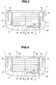
FIG. 3 is a front view showing a third embodiment provided to a window glass of an automotive rear door, and according to the present invention. -
FIG. 4 is a front view showing a fourth embodiment provided to a window glass of an automotive rear door, and according to the present invention. -
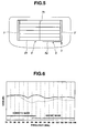
FIG. 5 is a front view showing an antenna of a comparative example 1. -
FIG. 6 is a frequency characteristic view of a horizontally polarized wave in the first embodiment and the comparative example. -
FIG. 7 is a frequency characteristic view of a vertically polarized wave in the first embodiment of the present invention and the comparative example. - Hereinafter, effects by the embodiments are illustrated.
When the rear window glass of the automobile has a short longitudinal length, it is not possible to ensure a space for an antenna which is for receiving AM/FM radio broadcast waves, and which needs a large area in an upper blank space above the defogger. In this case, even when the antenna is provided in peripheral blank spaces other than the upper blank space of the defogger, the defogger is used as the antenna, and first to fourth auxiliary elements including auxiliary horizontal strips, the auxiliary vertical strips and so on are provided in various portions of the defogger. With this, it is possible to improve the reception sensitivity of the FM radio broadcast wave, and to receive the FM broadcast wave with the high gain. - Moreover, the second vertical auxiliary element is provided for compensating the short longitudinal length of the heater strip of the defogger. With this, it is possible to lengthen the longitudinal length of the strip, and to become easy to receive the polarized wave in the vertical direction.
- Moreover, in a case in which the rear door of the automobile is a hatchback type, and made from the resin, the second auxiliary element branching from the defogger is adjacent to the metal reinforcement frames provided at least on upper side and right and left both sides of the opening portion of the door made from the resin, so as to achieve the capacitive coupling. With this, the defogger receives the radio wave received by the automobile body through the metal reinforcement frames and the second auxiliary element. Moreover, it is possible to receive the FM radio broadcast wave with the high gain through the first auxiliary element and the FM radio broadcast wave receiving antenna which achieve the capacitive coupling with the first auxiliary element.
- Moreover, the FM radio broadcast wave receiving antenna of this embodiment and the roof mount antenna (RMA) which is for receiving the AM/FM radio broadcast waves, and which is provided at a rear position of a roof of the automobile are arranged to achieve the diversity reception. With this, it is possible to receive the FM radio broadcast wave with the high gain.
- Moreover, the horizontal element of this example is adjacent to the first auxiliary horizontal strip of the first auxiliary element which has a predetermined length, which branches from the lower end of the bus bar of the defogger or the lowermost one of the horizontal heater strips, and which extends along the lowermost one of the horizontal heater strips, so as to achieve the capacitive coupling. With this, it is possible to receive the radio wave of the horizontally polarized wave received by the horizontal heater strips of eth defogger.
- Moreover, the vertical element extending from the feed point along the outside of the bus bar of the defogger is adjacent to the bus bar to achieve the capacitive coupling. With this, it is possible to receive the radio wave of the vertically polarized wave received by the defogger.
- As shown in
FIG. 3 , there is provided the firstauxiliary element 6 including at least the first auxiliaryhorizontal element 6a which branches from a lower end of one of thebus bars 3, 3' of thedefogger 2 of the automotiverear window glass 1, or the lowermost one of thehorizontal heater strips 2a, and which extends along the lowermost one of thehorizontal heater strips 2a, and the secondauxiliary element 7 including at least one of the second auxiliaryvertical strips bus bars 3, 3' of thedefogger 2 through the extension lines along the outsides of thevertical element 5b of the FM radio broadcastwave receiving antenna 5 or the outside of one of thebus bars 3, 3', which are apart from thebus bars 3, 3' in the outward direction, and which extend substantially parallel with each other. - In the FM broadcast wave receiving antenna, the first
auxiliary element 6 is adjacent to thehorizontal element 5a extending in the substantially horizontal direction from thefeed point 4 provided near the lower portion of one of thebus bars 3, 3' of thedefogger 2 to achieve the capacitive coupling. The structure ofFIG. 3 is a simplest structure pattern of theglass antenna 5 according to the present invention. - In a case in which a
perforated portion 20 for mounting a wiper is provided in a central portion of the lower blank space of thedefogger 2, in the firstauxiliary element 6, a foldedstrip 6b is formed by bending the end portion of the first auxiliaryhorizontal strip 6a in the vertical direction before the perforatedportion 20 for mounting the wiper, and then folding in an U-shape. However, in a case in which the perforatedportion 20 for mounting the wiper is not provided, the first auxiliaryhorizontal strip 6a may not be folded, and the first auxiliaryhorizontal strip 6a may extend in the horizontal direction to have a predetermined length. - Moreover, there is provided the second
auxiliary element 7 including at least one of the second auxiliaryvertical strips bus bars 3, 3' of thedefogger 2 through the extension lines, which are apart from thebus bars 3, 3' in the outward direction, and which are substantially in parallel with each other. In a case in which thevertical element 5b of the FM radio broadcastwave receiving antenna 5 is disposed outside thebus bars 3, 3', the secondauxiliary elements 7 are disposed, respectively, outside thevertical elements 5b of the FM radio broadcastwave receiving antenna 5. - This compensates for the short longitudinal length of the heater strip of the defogger. By providing the second vertical auxiliary element, it is possible to lengthen the longitudinal length of the strip, and to become easy to receive the polarized wave in the vertical direction.
- Moreover, in general, the rear hatchback door is not made from the resin, and the rear hatchback door is made from the metal. The window frame for mounting the window glass sheet is of course made from the metal. However, in a case in which the rear door is the hatchback door made from the resin, the second auxiliary
vertical strips auxiliary element 7 may be superimposed with the metal reinforcement frame connected with the metal body to keep a distance to achieve the capacitive coupling, or may be adjacent to the metal reinforcement frame to achieve the capacitive coupling. - The metal reinforcement frame of the rear door made from the resin includes reinforcement members which are made from the metal, and which are provided at least along the upper side, and both sides of the opening portion of the rear door.
- The second auxiliary elements branching from the defogger are adjacent to the metal reinforcement frame provided at least on the upper side, and the left and right both sides of the opening portion of the door made from the resin so as to achieve the capacitive coupling. With this, the defogger receives the radio wave received by the automobile body through the metal reinforcement frame and the second auxiliary element. Moreover, it is possible to receive the FM radio broadcast wave with the high gain through the first auxiliary element and the FM broadcast wave receiving antenna arranged to achieve the capacitive coupling with the first auxiliary element.
- In the FM broadcast
wave receiving antenna 5, thehorizontal element 5a is adjacent to the first auxiliaryhorizontal strip 6a to achieve the capacitive coupling. With this, the horizontally polarized component received by thedefogger 2 can be picked up by thehorizontal element 5a. Moreover, thevertical element 5b extending in the vertical direction along the outside of the bus bar 3' from thefeed point 4 is adjacent to thebus bar 3 to achieve the capacitive coupling. With this, the vertically polarized component received by thedefogger 2 can be picked up by thevertical element 5b. - Moreover, as shown in
FIG. 4 , in addition to the secondauxiliary element 7, it is optional to provide thirdauxiliary elements 8 each including a third auxiliaryhorizontal strip 8a which extends from the upper end of one of the bus bars 3, 3' of thedefogger 2 through the extension line to a portion near the middle portion, and which is adjacent to and along the upper side of the uppermost one of thehorizontal strips 2a of thedefogger 2. - Moreover, as shown in
FIG. 1 , in addition to the firstauxiliary element 6, the secondauxiliary elements 7 and the thirdauxiliary elements 8 of the pattern shown inFIG. 4 , it is optional to provide a fourthauxiliary element 9 including a fourth auxiliaryhorizontal strip 9a which branches from the substantially middle portion of the lowermost one of thehorizontal strips 2a of thedefogger 2, and which extends along the lowermost one of thehorizontal heater strips 2a in a direction opposite to thefeed point 4 to the lower end side of thebus bar 3, and a fourth auxiliaryvertical strip 9b which extends from the end of the fourth auxiliaryhorizontal strip 9a, and which is adjacent to the outside of thebus bar 3. - This invention is an antenna which is suitable for a case in which there is only a small space above the
defogger 2 for providing the antenna since the longitudinal length of therear window glass 1 is short. It is preferable that the roof mount antenna (RMA) which is for receiving the AM/FM broadcast waves, and which is provided on the roof of the automobile to protrude, and one of the above-mentioned FM broadcast wave receiving antennas provided in the lower blank space, or the lateral blank spaces of therear window glass 1 are arranged to achieve the diversity reception. - In this case, either of the roof mount antenna (RMA) or the
glass antenna 5 may be the main antenna. - The
defogger 2 is formed of a plurality of substantiallyhorizontal heater strips 2a that are arranged at intervals substantially in parallel in a central region of the automotiverear window glass 1, and connected at their both ends withconductive bus bars 3, 3'. A battery is connected between the bus bars 3, 3'. Thedefogger 2 is energized to heat thedefogger 2, so as to evaporate the small water droplets adhered on the outside surface of the window glass, that is, the fog, and to defog. However, the auxiliaryvertical strip 2b perpendicular to the plurality of thehorizontal heater strips vertical strip 2b is provided to pick up the radio wave of the vertically polarized wave component of the FM broadcast wave by the defogger. - The
horizontal element 5a of the FM broadcastwave receiving antenna 5 of this embodiment is adjacent to the first auxiliaryhorizontal strip 6a of the firstauxiliary element 6 which branches from and extends from the lowermost one of thehorizontal heater strips 2a of thedefogger 2 to achieve the capacitive coupling. - Although it is not shown in the drawings, the end portion of the
horizontal element 5a of the FM broadcastwave receiving antenna 5 may be folded to form the folded horizontal strip (not shown). Moreover, a part of this folded horizontal strip of thehorizontal element 5a may be adjacent to a part of thehorizontal strip 6a of the firstauxiliary element 6 to achieve the capacitive coupling. - The folded
strip 6b of the firstauxiliary element 6 may be folded on the lower side of the first auxiliaryhorizontal strip 6a. - It is preferable that the length of the
horizontal element 5a and the length of thevertical element 5b of the FM broadcastwave receiving antenna 5 extending from thefeed point 4 are, respectively, 250-450 mm and 200-400 mm in case of the FM broadcast wave receiving antenna of the frequency of 76-90 MHz for Japanese domestic use. Moreover, it is preferable that the length of thehorizontal element 5a and the length of thevertical element 5b are, respectively, 150-350 mm and 200-400 mm in case of the FM broadcast wave receiving antenna of the frequency of 88-108 MHz for North America, Europe, and Australia. - A length of the strip of portions that the
horizontal element 5a of the FM broadcastwave receiving antenna 5 and the firs auxiliaryhorizontal strip 6a of the firstauxiliary element 6 are adjacent to each other to achieve the capacitive coupling is 250-450 mm in case of the FM broadcast wave receiving antenna of the frequency of 76-90 MHz for Japanese domestic use. A distance between the strips of the portions that thehorizontal element 5a of the FM broadcastwave receiving antenna 5 and the first auxiliaryhorizontal strip 6a of the firstauxiliary element 6 are adjacent to each other to achieve the capacitive coupling is 5-15 mm in case of the FM broadcast wave receiving antenna of the frequency of 76-90 MHz for Japanese domestic use. - Moreover, a length of the strip of that portions is 150-350 mm in case of the FM broadcast wave receiving antenna of the frequency of 88-108 MHz for North America, Europe, and Australia. A distance between the strips of that portions is 5-15 mm in case of the FM broadcast wave receiving antenna of the frequency of 88-108 MHz for North America, Europe, and Australia.
- It is desirable that a length of the second auxiliary
horizontal strip 7a of the secondauxiliary element 7 is 40-80 mm, that a length of the second auxiliaryvertical strip 7b is 100-300 mm, and that a length of the third auxiliaryhorizontal strip 8a of the thirdauxiliary element 8 is 200-480 mm. - It is desirable that a length of the fourth
auxiliary strip 9a of the fourthauxiliary element 9 is 200-350 mm, and that a length of the fourth auxiliaryvertical strip 9b is 200-400 mm. - It is possible to obtain a quite satisfactory reception characteristic only by the single FM broadcast
wave receiving antenna 5. However, it is preferable that the diversity reception is performed by the two antennas of this antenna and the roof mount antenna (RMA) provided on the roof of the automobile. With this, it is possible to improve the directional characteristics, relative to a case of receiving by one of the two antennas. - The
bus bar 3 of thedefogger 2 was adjacent to thevertical element 5b extending from thefeed point 4 near the outside of the bus bar to achieve the capacitive coupling. With this, thevertical element 5b becomes easy to pick up the radio wave of the vertically polarized wave component received by thedefogger 2. Moreover, it is possible to obtain higher reception gain by theFM antenna 5. - The auxiliary
vertical strip 2b perpendicular to the plurality of the substantiallyhorizontal strips 2a of the defogging heater strips 2 is a neutral strip which is not energized, and which is not the defogging heater strip. The auxiliaryvertical strip 2b may not be necessarily provided. However, the auxiliaryvertical strip 2b is effective to make thedefogging heater strips 2 operate as the antenna, and to improve the reception gain of the radio wave of the FM broadcast wave by using the radio wave received by the defogging heater strips 2. - By appropriately combining the second to fourth auxiliary elements of the auxiliary elements, and connecting with the defogger, it is possible to improve the reception gain of the horizontally polarized wave component and the vertically polarized wave component of the FM broadcast wave received by the defogger, and to obtain the stable reception characteristic.
- Next, operations of this embodiment are illustrated.
- The
horizontal element 5a of the FM broadcastwave receiving antenna 5 of this embodiment was adjacent to the first auxiliaryhorizontal strip 6a of the firstauxiliary element 6 branching from and extending from the lowermost one of thehorizontal heater strips 2a of thedefogger 2 to achieve the capacitive coupling. This is because it was found by the experiment that the above-structure can obtain the reception gain higher than the radio wave of the horizontally polarized wave component of the FM broadcast wave received by theantenna 5, relative to a case in which thehorizontal element 5a' of the FM broadcast wave receiving antenna 5' is adjacent to thelowermost strip 2a of thedefogger 2 to achieve the capacitive coupling. - With this, it is possible to pick up the radio wave of the horizontally polarized wave component of the FM radio broadcast wave received by the
defogger 2 through the firstauxiliary element 6, and to import to thehorizontal element 5a. - Moreover, the
vertical element 5b was adjacent to the bus bar 3' of thedefogger 2 to achieve the capacitive coupling. With this, it is possible to pick up and import, by thevertical element 5b, the radio wave of the vertically polarized wave component of the FM radio broadcast wave received by thedefogger 2. - At least one second auxiliary
vertical strip 7b extending in the substantially vertical direction from the end of the second auxiliaryhorizontal strip 7a of the second auxiliary element which extends in the both outward directions from the upper ends of the bus bars 3, 3' of thedefogger 2 is disposed along the outside of thevertical strip 5b of the FM broadcastwave receiving antenna 5. This is because it is not possible to effectively receive the radio wave of the vertical component since the length of the strip of the defogger in the vertical direction is short. The length of the strip of the heater strip of thedefogger 2 in the vertical direction becomes long by providing the second auxiliaryvertical strip 7b extending from the bus bars 3, 3' through the extension lines. With this, it is possible to effectively receive the radio wave of the vertical component. - In a case in which the rear hatchback door is made from the resin, the second auxiliary vertical strip of the second auxiliary element is superimposed, with the distance, with the metal reinforcement frame grounded to the metal body, or is adjacent to the metal reinforcement frame to achieve the capacitive coupling. With this, it is possible to import the radio wave received by the automobile body by the capacitive coupling of the metal reinforcement frame and the second auxiliary element, and further to receive the FM radio broadcast wave with the high gain through the first auxiliary element and the FM radio broadcast wave receiving antenna which achieves the capacitive coupling with the first auxiliary element.
- Moreover, in the case in which the rear hatchback door is made from the resin, the metal reinforcement frame is formed, as the metal window frame, at least at the upper side and the both sides of the peripheral portion of the opening portion of the rear door for reinforcing the hatchback door made from the resin, and for importing the radio wave received by the automobile body.
- Moreover, the third
auxiliary element 8 was provided at the uppermost one of thehorizontal heater strip 2a of thedefogger 2. With this, it is possible to become easy to receive the radio wave of the FM broadcast wave (specifically, the vertically polarized wave) by adjusting the length of the horizontal strip to the wave length λ/4 of thecentral frequency 90 MHz of the FM broadcast wave band. The fourthauxiliary element 9 was provided at the lowermost one of thehorizontal heater strips 2a of thedefogger 2. With this, it is possible to adjust the impedance to the wave length of the target frequency. - Hereinafter, the present invention is illustrated in detail with reference to the drawings.
- As shown in
FIG. 1 , the FM broadcastwave receiving antenna 5 of frequency of 88-108 MHz for North America, Europe and Australia was provided in a corner portion in a lower space of thedefogger 2 of the window glass mounted in the metal window frame of the rear hatchback door for the automobile. Moreover, first to fourth auxiliary elements 6-9 were provided in peripheral blank spaces above and below thedefogger 2, and in peripheral blank spaces on left and right sides of thedefogger 2. The first to fourth auxiliary elements 6-9 were connected with thedefogger 2. - A distance of the upper blank space of the
defogger 2 between the uppermost one of thehorizontal heater strips 2a and theflange opening portion 21 is short, and is substantially 30 mm. A distance of the lower space of thedefogger 2 between the lowermost one of thehorizontal heater strips 2a and the lower side of the flange opening portion is 60 mm, and is short relative to the general distance. As to the lateral blank spaces, a distance between each of the bus bars 3, 3' and one of longitudinal sides of the flange opening is substantially 10 mm. However, there is a space with a distance of substantially 100 mm from the flange opening portion to the adhesive around the glass. - The FM broadcast
wave receiving antenna 5 includes ahorizontal element 5a extending in the horizontal direction from afeed point 4 provided near one of the bus bars 3, and avertical element 5b extending in the vertical direction from thefeed point 4. - A
perforated portion 20 is formed in a central space of the lower blank space of thedefogger 2. The perforatedportion 20 is for driving the wiper for the rear window glass. - Therefore, the first
auxiliary element 6 includes a first auxiliaryhorizontal strip 6a extending in the horizontal direction from an end of an extension line which branches from a portion of the lowermost one of the horizontal heater strips near theright bus bar 3 of thedefogger 2, and which extends in the downward direction; and a foldedstrip 6b formed by bending the end of the auxiliaryhorizontal strip 6a in the upward direction, and then further folding the end of the auxiliaryhorizontal strip 6a. - The
horizontal element 5a of the FM broadcastwave receiving antenna 5 of this embodiment was adjacent to first auxiliaryhorizontal strip 6a to achieve the capacitive coupling. Thevertical element 5b was adjacent to the bus bar 3' of thedefogger 2 to achieve the capacitive coupling. - The
auxiliary elements 7 were disposed, respectively, in the outward directions from ends of extension lines each extending in the upward direction from an upper end of one of thebus bar 3, 3' of thedefogger 2. Theauxiliary elements 8 were disposed, respectively, in the inward directions from the ends of the extension lines. - Each of the second
auxiliary elements 7 includes the second auxiliaryhorizontal strip 7a disposed in the outward direction from the end of one of the extension lines extending in the upward direction from the upper end of one of the bus bars 3, 3'; and two second vertical strips which extend in the downward direction from the end of one of the extension lines, and which are adjacent to each other. - Moreover, each of the third
auxiliary elements 8 includes a third auxiliaryhorizontal strip 8a extending in the inward direction from the end of the extension line to a substantially middle portion of thedefogger 2. - Furthermore, the fourth
auxiliary element 9 includes a fourth auxiliaryhorizontal strip 9a which branches from a substantially middle portion of the lowermost one of thehorizontal heater strips 2a of thedefogger 2, which extends toward the lower end side of thebus bar 3 that is opposite to thefeed point 4, and which is adjacent to and along the lowermost one of thehorizontal heater strips 2a; and a fourth auxiliaryvertical strip 9b which further extends from an end of the fourth auxiliaryhorizontal strip 9a, and which is adjacent to and along the outside of the lower end portion of thebus bar 3. - The
defogger 2 has a pattern shape including a plurality of thehorizontal heater strips vertical strip 2b perpendicular to the plurality of thehorizontal heater strips horizontal heater strips - The
glass plate 1 used in the first embodiment has a substantially rectangular shape. Theglass plate 1 has outline dimensions of an upper side of 1,200 mm, a lower side of 1,200 mm, and a height of 550 mm. An inside size of the flange of the window frame are an upper side of 1,100 mm, a lower side of 1,100 mm, and a height of 500 mm. -
- A length of the
horizontal element 5a of theantenna 5 of this embodiment = 215 mm - A length of the
vertical element 5b = 360 mm - A length of the first auxiliary
horizontal strip 6a of the firstauxiliary element 6 = 325 mm - A length of the folded
strip 6b = 250 mm - Each distance between the first auxiliary
horizontal strip 6a and the lowermost one of thehorizontal heater strips 2a of the defogger = 30 mm - A distance between the
horizontal element 5a and the first auxiliaryhorizontal strip 6a = 5mm - A distance between the
vertical element 5b and the bus bars 3, 3' = 10 mm - A length of the second auxiliary
horizontal strip 7a of the secondauxiliary element 7 = 65 mm - Lengths of the second auxiliary
vertical strips - A distance between the two second auxiliary
vertical strips - A distance between the second auxiliary
vertical strip 7b and the bus bar 3' = 30 mm - A length of the third auxiliary
horizontal strip 8a of the thirdauxiliary element 8 = 475 mm - A distance between the third auxiliary
horizontal strip 8a and the uppermost one of thehorizontal heater strips 2a of the defogger = 10 mm - A length of the fourth auxiliary
horizontal strip 9a of the fourthauxiliary element 9 = 340 mm - A length of the fourth auxiliary
vertical strip 9b = 375 mm - A distance between the fourth auxiliary
vertical strip 9a and the lowermost one of thehorizontal heater strips 2a = 5 mm - A distance between the fourth auxiliary
vertical strip 9b and thebus bar 3 = 10 mm - The
feed point 4 is located at a position which is apart from the lower end of the bus bar 3' by 65 mm. - The FM broadcast
wave receiving antenna 5, the auxiliary elements 6-9, the heatingconductive strips 2, thefeed point 4 and the bus bars 3, 3' are formed by printing on the glass sheet by the conductive paste such as silver paste, and then baking. - Thus-obtained window glass sheet was mounted in the rear window of the automobile. Moreover, the FM broadcast
wave receiving antenna 5 was connected from the feed point through a feeder line to an FM tuner (not shown). - The FM broadcast
wave receiving antenna 5 and a roof mount antenna (RMA) (not shown) were arranged to achieve the diversity reception so as to improve the directional characteristics. - As shown by heavy lines of frequency characteristic views of
FIGS. 6 and7 , in case of receiving by theFM antenna 5, the average reception gain of the horizontally polarized wave of the FM broadcast wave band of 88 MHz - 108 MHz for North America, Europe, and Australia became -18.5 dB, and the average reception gain of the vertically polarized wave became -16.5 dB (dipole ratio). As a result of the diversity reception by the two antenna systems of theFM antenna 5 and the AM/FM roof mount antenna (RMA) (not shown), it was found to obtain a reception gain with very good directional characteristics in 88 MHz - 108 MHz. - In this way, the various auxiliary elements were provided to the defogger to receive the radio wave of the FM broadcast wave with the high gain. By the FM broadcast
wave receiving antenna 5 arranged to achieve the capacitive coupling with the first auxiliary element branching from and connecting with thedefogger 2 which received the radio wave of the FM broadcast wave with the high gain, it became possible to pick up the FM broadcast wave with the high sensitivity. - In the second embodiment shown in
FIG. 2 , the rear hatchback door for the automobile was made from the resin. The FM broadcastwave receiving antenna 5 of the frequency of 88-108 MHz for North America, Europe and Australia was provided in a corner portion in a lower space of thedefogger 2 of the window glass mounted in the opening portion of the window frame. Moreover, first to fourth auxiliary elements 6-9 were provided in peripheral blank spaces above and below thedefogger 2, and in peripheral blank spaces on left and right sides of thedefogger 2. The first to fourth auxiliary elements 6-9 were connected with thedefogger 2. - The patterns, the sizes and so on of the FM broadcast
wave receiving antenna 5 and the first to fourth auxiliary elements 6-9 are identical to those in the first embodiment. In this second embodiment, the rear door is the hatchback door made from the resin. The second auxiliaryvertical strips auxiliary element 7 and the metal reinforcement frame connected with the metal body were superimposed to maintain a distance capable of achieving the capacitive coupling so as to achieve the capacitive coupling. The rear door made from the resin was provided with the metal reinforcement frames extending along the upper side and the both lateral sides of the opening portion of the rear door. - Each of the second
auxiliary elements 7 includes the two second auxiliaryvertical strips - Like the first embodiment, the FM broadcast
wave receiving antenna 5 was connected from thefeed point 4 to a tuner (not shown). Moreover, in this embodiment, a length of each strip of the FM broadcastwave receiving antenna 5, and a length and a distance of each strip of the first auxiliary element are identical to those of the first embodiment. - The FM broadcast
wave receiving antenna 5, thedefogger 2, thefeed point 4, and the bus bars 3, 3' are formed by printing on the glass sheet by the conductive paste such as the silver paste, and then baking. - Thus-obtained window glass sheet was mounted in the rear window of the automobile. Moreover, the FM broadcast
wave receiving antenna 5 was connected from thefeed point 4 through the feeder line to the FM tuner (not shown). - The FM broadcast
wave receiving antenna 5 and the roof mount antenna (RMA) (not shown) were arranged to achieve the diversity reception so as to improve the directional characteristics - In case of receiving by the
FM antenna 5, the average reception gain of the horizontally polarized wave of the FM broadcast wave band of 88 MHz - 108 MHz for North America, Europe, and Australia became -18.1 dB, and the average reception gain of the vertically polarized wave became -16.3 dB (the dipole rati0). As a result of the diversity reception by the two FM antenna systems of theFM antenna 5 and the AM/FM roof mount antenna (RMA) (not shown), it was found to obtain a reception gain with very good directional characteristics in 88 MHz - 108 MHz. - In a third embodiment shown in
FIG. 3 , the firstauxiliary element 6 and the secondauxiliary element 7 were connected with the defogger of the first embodiment. Thehorizontal element 5a of theFM antenna 5 was adjacent to the first auxiliaryhorizontal strip 6a of the firstauxiliary element 6 to achieve the capacitive coupling. Thevertical element 5b of theFM antenna 5 was adjacent to the bus bar 3' of the defogger to achieve the capacitive coupling. Lengths of the firstauxiliary element 6 and the secondauxiliary element 7 are identical to those of the first embodiment. Distances between thedefogger 2 and each of the firstauxiliary element 6 and the secondauxiliary element 7 are identical to those of the first embodiment.
In the third embodiment, there are not provided the third and fourth auxiliary elements, unlike the second embodiment. - Like the first embodiment, the FM broadcast
wave receiving antenna 5 was connected from thefeed point 4 to the tuner (not shown). Moreover, in this embodiment, a length of each strip of the FM broadcastwave receiving antenna 5, and a length and a distance of each strip of the first auxiliary element are identical to those of the first embodiment. - The FM broadcast
wave receiving antenna 5, thedefogger 2, thefeed point 4, and the bus bars 3, 3' are formed by printing on the glass sheet by the conductive paste such as the silver paste, and then baking. - Thus-obtained window glass sheet was mounted in the rear window of the automobile. Moreover, the FM broadcast
wave receiving antenna 5 was connected from thefeed point 4 through the feeder line to the FM tuner (not shown). - The FM broadcast
wave receiving antenna 5 and the roof mount antenna (RMA) (not shown) were arranged to achieve the diversity reception so as to improve the directional characteristics. - In case of receiving by the
FM antenna 5, the average reception gain of the horizontally polarized wave of the FM broadcast wave band of 88 MHz - 108 MHz for North America, Europe, and Australia became -19.0 dB, and the average reception gain of the vertically polarized wave became -17.1 dB (the dipole ratio). As a result of the diversity reception by the two FM antenna systems of theFM antenna 5 and the AM/FM roof mount antenna (RMA) (not shown), it was found to obtain a reception gain with very good directional characteristics in 88 MHz - 108 MHz. - In a fourth embodiment shown in
FIG. 4 , the firstauxiliary element 6, the secondauxiliary element 7 and the thirdauxiliary element 8 were connected with the defogger of the first embodiment. Thehorizontal element 5a of theFM antenna 5 was adjacent to the first auxiliaryhorizontal strip 6a of the firstauxiliary element 6 to achieve the capacitive coupling. Thevertical element 5b of theFM antenna 5 was adjacent to the bus bar 3' of the defogger to achieve the capacitive coupling. Lengths of the firstauxiliary element 6, the secondauxiliary element 7 and the thirdauxiliary element 8 are identical to those of the first embodiment. Distances between thedefogger 2 and each of the firstauxiliary element 6, the secondauxiliary element 7 and the thirdauxiliary element 8 are identical to those of the first embodiment. In the fourth embodiment, there are not provided the fourth auxiliary element, unlike the first embodiment. - Like the first embodiment, the FM broadcast
wave receiving antenna 5 was connected from thefeed point 4 to the tuner (not shown). Moreover, in this embodiment, a length of each strip of the FM broadcastwave receiving antenna 5, and a length and a distance of each strip of the first auxiliary element are identical to those of the first embodiment. - The FM broadcast
wave receiving antenna 5, thedefogger 2, thefeed point 4, and the bus bars 3, 3' are formed by printing on the glass sheet by the conductive paste such as the silver paste, and then baking. - Thus-obtained window glass sheet was mounted in the rear window of the automobile. Moreover, the FM broadcast
wave receiving antenna 5 was connected from thefeed point 4 through the feeder line to the FM tuner (not shown). - The FM broadcast
wave receiving antenna 5 and the roof mount antenna (RMA) (not shown) were arranged to achieve the diversity reception so as to improve the directional characteristics. - In case of receiving by the
FM antenna 5, the average reception gain of the horizontally polarized wave of the FM broadcast wave band of 88 MHz - 108 MHz for North America, Europe, and Australia became -18.8 dB, and the average reception gain of the vertically polarized wave became -16.8 dB (the dipole ratio). As a result of the diversity reception by the two FM antenna systems of theFM antenna 5 and the AM/FM roof mount antenna (RMA) (not shown), it was found to obtain a reception gain with very good directional characteristics in 88 MHz - 108 MHz. - As shown in
FIG. 5 , an FM broadcast wave receiving antenna 5' of the frequency of 88-108 MHz for North America, Europe and Australia was provided in a corner portion in a lower space of thedefogger 2 of the rear window glass for the automobile. - The FM broadcast wave receiving antenna 5' includes a
horizontal element 5a' extending in the horizontal direction from a feed point 4' provided near a lower end portion of a right bus bar 3' of thedefogger 2. - The
horizontal element 5a' was adjacent to the lowermost one of thehorizontal heater strips 5a of the defogger to achieve the capacitive coupling. - The FM broadcast wave receiving antenna 5', the defogger 2', the
feed point 4, and the bus bars 3, 3' are formed by printing on the glass sheet by the conductive paste such as the silver paste, and then baking. - Thus-obtained window glass sheet was mounted in the rear window of the automobile. Moreover, the FM broadcast
wave receiving antenna 5 was connected from thefeed point 4 through the feeder line to the FM tuner (not shown). - As shown by narrow lines of frequency characteristic views of
FIGS. 6 and7 , in case of receiving by the FM antenna 5', the average reception gain of the horizontally polarized wave of the FM broadcast wave band of 88 MHz - 108 MHz for North America, Europe, and Australia became -24.8 dB, the average reception gain of the vertically polarized wave became -21.2 dB (the dipole ratio). It was found that a satisfactory reception gain can not be obtained relative to theFM antenna 5.
Claims (5)
- An automotive glass antenna which is an FM radio broadcast wave receiving antenna provided in blank spaces below or lateral sides of a defogger of a window glass provided in a rear door of a hatchback type of an automobile, the automotive glass antenna comprising:a first auxiliary element including at least a first auxiliary horizontal strip which branches from a lower end of a bus bar of the defogger, or from a lowermost horizontal heater strip, and which extends along the lowermost heater strip;a second auxiliary element including at least a second auxiliary vertical strip which extends from an upper end of each bus bar through an extension line, and which is apart from the bus bar in an outward direction;a horizontal element which extends in a substantially horizontal direction from a feed point provided near a lower portion of the bus bar of the defogger, and which is adjacent to the first auxiliary horizontal strip to achieve a capacitive coupling; anda vertical element which extends from the feed point along an outside of the bus bar, and which is adjacent to the bus bar to achieve the capacitive coupling.
- The automotive glass antenna as defined in claim 1, wherein the automotive glass antenna comprises a third auxiliary element including a third auxiliary horizontal strip which extends from the upper end of each bus bar of the defogger through the extension line along an upper side of an uppermost heater horizontal strip of the defogger, to a portion near a middle portion of the uppermost heater horizontal strip, and which is adjacent to the upper side of the uppermost heater horizontal strip.
- The automotive glass antenna as defined in claim 1 or 2, wherein the automotive glass antenna comprises a fourth auxiliary element including a fourth auxiliary horizontal strip which branches from a substantially middle portion of the lowermost horizontal heater strip of the defogger, and which extends along the lowermost horizontal heater strip in a direction opposite to the feed point, and a fourth auxiliary vertical strip which extends from an end of the fourth auxiliary horizontal strip, and which is adjacent to an outside of the bus bar.
- The automotive glass antenna as defined in one of claims 1 to 3, wherein the rear door is made from a resin; metal reinforcement frames are provided at least in upper side, both lateral sides of a periphery portion of an opening portion of the rear door; the metal reinforcement frames are grounded to a metal body; the second auxiliary vertical strip of the second auxiliary element is superimposed with or adjacent to the metal reinforcement frame with a distance to achieve the capacitive coupling.
- The automotive glass antenna as defined in one of claims 1 to 4, wherein the rear window glass is a window glass having no blank space above the defogger for providing the antenna; and the FM broadcast wave receiving antenna provided in the blank spaces below or on the lateral sides of the rear window glass is arranged to achieve a diversity reception with a roof mount antenna for receiving AM/FM broadcast waves.
Applications Claiming Priority (2)
| Application Number | Priority Date | Filing Date | Title |
|---|---|---|---|
| JP2007275572A JP5339710B2 (en) | 2007-10-23 | 2007-10-23 | Glass antenna for automobile |
| PCT/JP2008/068872 WO2009054324A1 (en) | 2007-10-23 | 2008-10-17 | Automotive glass antenna |
Publications (2)
| Publication Number | Publication Date |
|---|---|
| EP2207239A1 true EP2207239A1 (en) | 2010-07-14 |
| EP2207239A4 EP2207239A4 (en) | 2011-11-23 |
Family
ID=40579430
Family Applications (1)
| Application Number | Title | Priority Date | Filing Date |
|---|---|---|---|
| EP08842908A Withdrawn EP2207239A4 (en) | 2007-10-23 | 2008-10-17 | GLASS AUTOMOTIVE ANTENNA |
Country Status (6)
| Country | Link |
|---|---|
| US (1) | US8334813B2 (en) |
| EP (1) | EP2207239A4 (en) |
| JP (1) | JP5339710B2 (en) |
| CN (1) | CN101836327B (en) |
| CA (1) | CA2702167A1 (en) |
| WO (1) | WO2009054324A1 (en) |
Cited By (4)
| Publication number | Priority date | Publication date | Assignee | Title |
|---|---|---|---|---|
| CN102064378A (en) * | 2010-11-15 | 2011-05-18 | 蒋小平 | Automobile window glass amplitude modulation and frequency modulation shared printed antenna system |
| EP3101728A1 (en) * | 2015-06-05 | 2016-12-07 | Asahi Glass Company, Limited | Glass antenna for vehicle and rear window glass with glass antenna for vehicle |
| US20180233803A1 (en) * | 2017-02-14 | 2018-08-16 | Asahi Glass Company, Limited | Window glass for vehicle |
| EP3422474A4 (en) * | 2016-06-03 | 2019-04-03 | Mazda Motor Corporation | GLASS ANTENNA |
Families Citing this family (11)
| Publication number | Priority date | Publication date | Assignee | Title |
|---|---|---|---|---|
| JP6163986B2 (en) * | 2013-09-11 | 2017-07-19 | セントラル硝子株式会社 | Back door and glass antenna |
| JP6221773B2 (en) * | 2014-01-27 | 2017-11-01 | セントラル硝子株式会社 | Glass antenna |
| JP6413429B2 (en) * | 2014-07-24 | 2018-10-31 | セントラル硝子株式会社 | Glass antenna and back door |
| JP2016043842A (en) * | 2014-08-25 | 2016-04-04 | セントラル硝子株式会社 | back door |
| JP6459650B2 (en) * | 2015-03-09 | 2019-01-30 | セントラル硝子株式会社 | Glass antenna for automobile |
| JP6812825B2 (en) * | 2017-02-14 | 2021-01-13 | Agc株式会社 | Glass antennas and windowpanes for vehicles |
| JP2019043453A (en) * | 2017-09-05 | 2019-03-22 | 日本板硝子株式会社 | Rear glass and back door having rear glass |
| EP3987441B1 (en) * | 2019-06-24 | 2023-04-26 | Saint-Gobain Glass France | Heatable vehicle pane with a transponder |
| JP7283269B2 (en) * | 2019-06-28 | 2023-05-30 | Agc株式会社 | Back door and rear glass |
| JP7589611B2 (en) | 2021-03-23 | 2024-11-26 | Agc株式会社 | Back door and rear window |
| JP7677048B2 (en) * | 2021-08-04 | 2025-05-15 | Agc株式会社 | Vehicle window glass |
Family Cites Families (20)
| Publication number | Priority date | Publication date | Assignee | Title |
|---|---|---|---|---|
| JPH03184401A (en) | 1989-12-13 | 1991-08-12 | Central Glass Co Ltd | Glass antenna for vehicle |
| US5177493A (en) | 1990-03-05 | 1993-01-05 | Pioneer Electronic Corporation | Antenna device for movable body |
| JP2638708B2 (en) * | 1992-03-06 | 1997-08-06 | セントラル硝子株式会社 | Glass antenna for automobile |
| DE69313165T2 (en) * | 1992-03-06 | 1997-12-18 | Central Glass Co Ltd | Window antenna for motor vehicles |
| JPH06177625A (en) * | 1992-10-06 | 1994-06-24 | Central Glass Co Ltd | Automotive glass antenna |
| JP3458975B2 (en) * | 1993-12-28 | 2003-10-20 | マツダ株式会社 | Glass antenna for vehicle and setting method thereof |
| JP2962394B2 (en) | 1994-03-24 | 1999-10-12 | セントラル硝子株式会社 | Glass antenna for vehicles |
| JPH09153716A (en) * | 1995-11-30 | 1997-06-10 | Central Glass Co Ltd | Glass antenna for vehicle |
| JP3588896B2 (en) * | 1996-02-26 | 2004-11-17 | 旭硝子株式会社 | Automotive glass antenna |
| US5933119A (en) | 1997-02-20 | 1999-08-03 | Central Glass Company Limited | Glass antenna system for vehicles |
| JPH10270924A (en) * | 1997-03-21 | 1998-10-09 | Central Glass Co Ltd | On-vehicle glass antenna |
| TW508865B (en) * | 2000-06-22 | 2002-11-01 | Asahi Glass Co Ltd | Glass antenna for an automobile |
| JP2003078319A (en) | 2001-09-03 | 2003-03-14 | Central Glass Co Ltd | Glass antenna for vehicle |
| JP2003142913A (en) | 2001-10-31 | 2003-05-16 | Central Glass Co Ltd | Glass antenna for vehicle |
| JP3974087B2 (en) * | 2003-06-30 | 2007-09-12 | セントラル硝子株式会社 | Glass antenna for vehicles |
| JP2005130415A (en) * | 2003-10-27 | 2005-05-19 | Central Glass Co Ltd | Glass antenna for vehicle |
| JP2006033498A (en) * | 2004-07-16 | 2006-02-02 | Nippon Sheet Glass Co Ltd | Glass antenna device for vehicle |
| CN2735558Y (en) * | 2004-08-13 | 2005-10-19 | 柯玉荣 | Automotive Printed Antenna Device Using Induction to Increase Different Phase Reception |
| JP4370303B2 (en) * | 2005-03-29 | 2009-11-25 | セントラル硝子株式会社 | Glass antenna for vehicles |
| US7558555B2 (en) * | 2005-11-17 | 2009-07-07 | Delphi Technologies, Inc. | Self-structuring subsystems for glass antenna |
-
2007
- 2007-10-23 JP JP2007275572A patent/JP5339710B2/en not_active Expired - Fee Related
-
2008
- 2008-10-17 CN CN2008801125986A patent/CN101836327B/en not_active Expired - Fee Related
- 2008-10-17 EP EP08842908A patent/EP2207239A4/en not_active Withdrawn
- 2008-10-17 US US12/739,116 patent/US8334813B2/en not_active Expired - Fee Related
- 2008-10-17 WO PCT/JP2008/068872 patent/WO2009054324A1/en not_active Ceased
- 2008-10-17 CA CA2702167A patent/CA2702167A1/en not_active Abandoned
Cited By (8)
| Publication number | Priority date | Publication date | Assignee | Title |
|---|---|---|---|---|
| CN102064378A (en) * | 2010-11-15 | 2011-05-18 | 蒋小平 | Automobile window glass amplitude modulation and frequency modulation shared printed antenna system |
| EP3101728A1 (en) * | 2015-06-05 | 2016-12-07 | Asahi Glass Company, Limited | Glass antenna for vehicle and rear window glass with glass antenna for vehicle |
| EP3422474A4 (en) * | 2016-06-03 | 2019-04-03 | Mazda Motor Corporation | GLASS ANTENNA |
| AU2017275918B2 (en) * | 2016-06-03 | 2019-12-19 | Mazda Motor Corporation | Glass antenna |
| US10541463B2 (en) | 2016-06-03 | 2020-01-21 | Mazda Motor Corporation | Glass antenna |
| US20180233803A1 (en) * | 2017-02-14 | 2018-08-16 | Asahi Glass Company, Limited | Window glass for vehicle |
| US10651536B2 (en) | 2017-02-14 | 2020-05-12 | AGC Inc. | Window glass for vehicle |
| EP3361564B1 (en) * | 2017-02-14 | 2020-08-12 | AGC Inc. | Window glass for vehicle |
Also Published As
| Publication number | Publication date |
|---|---|
| JP5339710B2 (en) | 2013-11-13 |
| CN101836327B (en) | 2013-04-24 |
| US20100220020A1 (en) | 2010-09-02 |
| EP2207239A4 (en) | 2011-11-23 |
| US8334813B2 (en) | 2012-12-18 |
| WO2009054324A1 (en) | 2009-04-30 |
| JP2009105665A (en) | 2009-05-14 |
| CA2702167A1 (en) | 2009-04-30 |
| CN101836327A (en) | 2010-09-15 |
Similar Documents
| Publication | Publication Date | Title |
|---|---|---|
| US8334813B2 (en) | Automotive glass antenna | |
| US9136583B2 (en) | Automotive window antenna | |
| JP4370303B2 (en) | Glass antenna for vehicles | |
| US8330663B2 (en) | Glass antenna for vehicle | |
| EP2343773B1 (en) | Vehicular glass antenna | |
| US7019700B2 (en) | Glass antenna system for vehicles | |
| JP3974087B2 (en) | Glass antenna for vehicles | |
| JP4941171B2 (en) | Glass antenna for vehicles | |
| JP4941158B2 (en) | Glass antenna for vehicles | |
| US20160268670A1 (en) | Automotive Glass Antenna | |
| US6437749B2 (en) | Glass antenna for side windshield of automotive vehicle | |
| JP4225373B2 (en) | Glass antenna for vehicles | |
| JPH09153716A (en) | Glass antenna for vehicle | |
| JP3555716B2 (en) | Glass antenna for vehicles | |
| JP3556830B2 (en) | Glass antenna for automobile | |
| JP3491808B2 (en) | Glass antenna for automobile | |
| JP3599949B2 (en) | Glass antenna for vehicles | |
| JPH10126131A (en) | Vehicle-use glass antenna | |
| JP2009159318A (en) | Glass antenna for automobile | |
| JPH10163726A (en) | Glass antenna for vehicle |
Legal Events
| Date | Code | Title | Description |
|---|---|---|---|
| PUAI | Public reference made under article 153(3) epc to a published international application that has entered the european phase |
Free format text: ORIGINAL CODE: 0009012 |
|
| 17P | Request for examination filed |
Effective date: 20100423 |
|
| AK | Designated contracting states |
Kind code of ref document: A1 Designated state(s): AT BE BG CH CY CZ DE DK EE ES FI FR GB GR HR HU IE IS IT LI LT LU LV MC MT NL NO PL PT RO SE SI SK TR |
|
| AX | Request for extension of the european patent |
Extension state: AL BA MK RS |
|
| DAX | Request for extension of the european patent (deleted) | ||
| A4 | Supplementary search report drawn up and despatched |
Effective date: 20111025 |
|
| RIC1 | Information provided on ipc code assigned before grant |
Ipc: B60J 1/00 20060101AFI20111020BHEP Ipc: H01Q 1/12 20060101ALI20111020BHEP Ipc: H01Q 1/32 20060101ALI20111020BHEP |
|
| STAA | Information on the status of an ep patent application or granted ep patent |
Free format text: STATUS: EXAMINATION IS IN PROGRESS |
|
| 17Q | First examination report despatched |
Effective date: 20171024 |
|
| STAA | Information on the status of an ep patent application or granted ep patent |
Free format text: STATUS: THE APPLICATION IS DEEMED TO BE WITHDRAWN |
|
| 18D | Application deemed to be withdrawn |
Effective date: 20180104 |