EP2207051A1 - Elément de sécurité ainsi que procédé destiné à la fabrication d'un support d'éléments de sécurité - Google Patents
Elément de sécurité ainsi que procédé destiné à la fabrication d'un support d'éléments de sécurité Download PDFInfo
- Publication number
- EP2207051A1 EP2207051A1 EP09016065A EP09016065A EP2207051A1 EP 2207051 A1 EP2207051 A1 EP 2207051A1 EP 09016065 A EP09016065 A EP 09016065A EP 09016065 A EP09016065 A EP 09016065A EP 2207051 A1 EP2207051 A1 EP 2207051A1
- Authority
- EP
- European Patent Office
- Prior art keywords
- layer
- zones
- security element
- master
- pattern
- Prior art date
- Legal status (The legal status is an assumption and is not a legal conclusion. Google has not performed a legal analysis and makes no representation as to the accuracy of the status listed.)
- Withdrawn
Links
Images

Classifications
-
- B—PERFORMING OPERATIONS; TRANSPORTING
- B42—BOOKBINDING; ALBUMS; FILES; SPECIAL PRINTED MATTER
- B42D—BOOKS; BOOK COVERS; LOOSE LEAVES; PRINTED MATTER CHARACTERISED BY IDENTIFICATION OR SECURITY FEATURES; PRINTED MATTER OF SPECIAL FORMAT OR STYLE NOT OTHERWISE PROVIDED FOR; DEVICES FOR USE THEREWITH AND NOT OTHERWISE PROVIDED FOR; MOVABLE-STRIP WRITING OR READING APPARATUS
- B42D25/00—Information-bearing cards or sheet-like structures characterised by identification or security features; Manufacture thereof
- B42D25/40—Manufacture
-
- G—PHYSICS
- G02—OPTICS
- G02B—OPTICAL ELEMENTS, SYSTEMS OR APPARATUS
- G02B5/00—Optical elements other than lenses
- G02B5/18—Diffraction gratings
- G02B5/1847—Manufacturing methods
- G02B5/1857—Manufacturing methods using exposure or etching means, e.g. holography, photolithography, exposure to electron or ion beams
-
- B—PERFORMING OPERATIONS; TRANSPORTING
- B42—BOOKBINDING; ALBUMS; FILES; SPECIAL PRINTED MATTER
- B42D—BOOKS; BOOK COVERS; LOOSE LEAVES; PRINTED MATTER CHARACTERISED BY IDENTIFICATION OR SECURITY FEATURES; PRINTED MATTER OF SPECIAL FORMAT OR STYLE NOT OTHERWISE PROVIDED FOR; DEVICES FOR USE THEREWITH AND NOT OTHERWISE PROVIDED FOR; MOVABLE-STRIP WRITING OR READING APPARATUS
- B42D25/00—Information-bearing cards or sheet-like structures characterised by identification or security features; Manufacture thereof
- B42D25/20—Information-bearing cards or sheet-like structures characterised by identification or security features; Manufacture thereof characterised by a particular use or purpose
- B42D25/29—Securities; Bank notes
-
- B—PERFORMING OPERATIONS; TRANSPORTING
- B42—BOOKBINDING; ALBUMS; FILES; SPECIAL PRINTED MATTER
- B42D—BOOKS; BOOK COVERS; LOOSE LEAVES; PRINTED MATTER CHARACTERISED BY IDENTIFICATION OR SECURITY FEATURES; PRINTED MATTER OF SPECIAL FORMAT OR STYLE NOT OTHERWISE PROVIDED FOR; DEVICES FOR USE THEREWITH AND NOT OTHERWISE PROVIDED FOR; MOVABLE-STRIP WRITING OR READING APPARATUS
- B42D25/00—Information-bearing cards or sheet-like structures characterised by identification or security features; Manufacture thereof
- B42D25/30—Identification or security features, e.g. for preventing forgery
- B42D25/328—Diffraction gratings; Holograms
-
- B—PERFORMING OPERATIONS; TRANSPORTING
- B42—BOOKBINDING; ALBUMS; FILES; SPECIAL PRINTED MATTER
- B42D—BOOKS; BOOK COVERS; LOOSE LEAVES; PRINTED MATTER CHARACTERISED BY IDENTIFICATION OR SECURITY FEATURES; PRINTED MATTER OF SPECIAL FORMAT OR STYLE NOT OTHERWISE PROVIDED FOR; DEVICES FOR USE THEREWITH AND NOT OTHERWISE PROVIDED FOR; MOVABLE-STRIP WRITING OR READING APPARATUS
- B42D25/00—Information-bearing cards or sheet-like structures characterised by identification or security features; Manufacture thereof
- B42D25/40—Manufacture
- B42D25/405—Marking
- B42D25/415—Marking using chemicals
- B42D25/42—Marking using chemicals by photographic processes
-
- G—PHYSICS
- G02—OPTICS
- G02B—OPTICAL ELEMENTS, SYSTEMS OR APPARATUS
- G02B5/00—Optical elements other than lenses
- G02B5/32—Holograms used as optical elements
-
- B42D2033/04—
-
- B42D2035/20—
-
- B42D2035/24—
-
- G—PHYSICS
- G02—OPTICS
- G02B—OPTICAL ELEMENTS, SYSTEMS OR APPARATUS
- G02B5/00—Optical elements other than lenses
- G02B5/18—Diffraction gratings
- G02B5/1866—Transmission gratings characterised by their structure, e.g. step profile, contours of substrate or grooves, pitch variations, materials
- G02B5/1871—Transmissive phase gratings
-
- Y—GENERAL TAGGING OF NEW TECHNOLOGICAL DEVELOPMENTS; GENERAL TAGGING OF CROSS-SECTIONAL TECHNOLOGIES SPANNING OVER SEVERAL SECTIONS OF THE IPC; TECHNICAL SUBJECTS COVERED BY FORMER USPC CROSS-REFERENCE ART COLLECTIONS [XRACs] AND DIGESTS
- Y10—TECHNICAL SUBJECTS COVERED BY FORMER USPC
- Y10T—TECHNICAL SUBJECTS COVERED BY FORMER US CLASSIFICATION
- Y10T428/00—Stock material or miscellaneous articles
- Y10T428/24—Structurally defined web or sheet [e.g., overall dimension, etc.]
- Y10T428/24479—Structurally defined web or sheet [e.g., overall dimension, etc.] including variation in thickness
- Y10T428/24612—Composite web or sheet
-
- Y—GENERAL TAGGING OF NEW TECHNOLOGICAL DEVELOPMENTS; GENERAL TAGGING OF CROSS-SECTIONAL TECHNOLOGIES SPANNING OVER SEVERAL SECTIONS OF THE IPC; TECHNICAL SUBJECTS COVERED BY FORMER USPC CROSS-REFERENCE ART COLLECTIONS [XRACs] AND DIGESTS
- Y10—TECHNICAL SUBJECTS COVERED BY FORMER USPC
- Y10T—TECHNICAL SUBJECTS COVERED BY FORMER US CLASSIFICATION
- Y10T428/00—Stock material or miscellaneous articles
- Y10T428/26—Web or sheet containing structurally defined element or component, the element or component having a specified physical dimension
Definitions
- the invention relates to a security element with a transparent layer with non-homogeneous refractive index and a method for producing such a security element.
- a photopolymer film in the volume of information is stored holographically.
- a security element with a laminated between two carrier layers photosensitive layer described in which an optically perceptible information, in particular a 3D hologram of an object, is stored and visible when illuminated is stored and visible when illuminated.
- the invention is based on the object of specifying an improved security element for securing security documents and a method for producing such a security element.
- a security element having a top side and a bottom side, which has a transparent layer with non-homogeneous refractive index, in which a plurality of Bragg planes are formed by refractive index variation, wherein the transparent layer has a layer thickness of 5 .mu.m to 200 .mu.m and the transparent layer has a plurality of first zones having a minimum dimension of less than 300 ⁇ m arranged adjacent to each other according to a first raster in a one- or two-dimensional sequence, and in each of which the Bragg planes of the transparent layer form a respective one transmissive optical imaging function are formed.
- the object is further achieved by a method for producing a security element, in which a photosensitive layer with a layer thickness between 5 .mu.m and 200 .mu.m is provided, the photosensitive layer is exposed such that in the photosensitive layer, a plurality of first zones with a smallest Dimension of less than 300 microns is formed, which are arranged according to a first grid in a one or two-dimensional sequence adjacent to each other and in each of which a plurality of Bragg levels formed by Brechressvariation are formed to form a respective transmissive imaging function and in which the photosensitive Layer is then cured.
- the invention In contrast to known security elements, according to the invention, no (three-dimensional) representation of an object or other optically variable information is generated by the Bragg planes, but the Bragg planes are formed in a multiplicity of regions below the resolving power of the human eye to form optical ones transmissive imaging functions. As a result, novel optical effects can be generated, which are used as optical security features. Furthermore, the security feature according to the invention is distinguished by the fact that it is produced by galvanic or mechanical contact copying or holographic copying can not be replicated. As a result, the security against forgery of the security element, in particular also in comparison to conventional refractive lenses, further improved. The invention thus provides a security element which is very difficult to imitate and falsify for securing security documents, which nevertheless can be manufactured industrially in a simple and cost-effective manner.
- the photosensitive layer is preferably composed of photopolymer, silver halide emulsions, dichromated gelatin.
- the Bragg planes of the transparent layer are formed in the first zones to form identical transmissive imaging functions.
- interesting optically variable effects can be achieved, in particular in connection with the pattern layer described below.
- the Bragg planes of the transparent layer are formed in the first zones to form different transmissive imaging functions. This can be interesting movement effects achieve and encode macroscopic information in the security element.
- the Bragg planes of the transparent layer are formed in a first group of first zones to form identical first transmissive imaging functions and formed in a second group of first zones to form identical second transmissive imaging functions, wherein the first and second imaging functions are different imaging functions.
- a plurality of first zones of the first group are arranged adjacent to one another and occupy a third area with a smallest dimension of more than 300 ⁇ m.
- a plurality of first zones of the second group are arranged adjacent to one another and occupy a fourth area with a smallest dimension of more than 300 ⁇ m.
- the Bragg planes of the transparent layer are formed to form different transmissive optical imaging functions in the first zones, wherein the imaging functions of adjacent first zones change continuously in a spatial direction.
- the Bragg planes in the first zones are each arranged parallel to one another and spaced from one another in each case between 200 nm and 700 nm, preferably between 260 nm and 460 nm, in particular with a refractive index of the material arranged between the Bragg planes of approximately 1.5.
- the Bragg planes are preferably arranged equidistant from each other in the first zones.
- the Bragg planes preferably each enclose an angle between approximately 5 ° and approximately 45 ° with the plane defined by the upper side of the security element. More preferably, the angle here varies with depth, i. depending on a direction perpendicular to the plane spanned. Investigations have shown that, in compliance with these conditions, a particularly good optical efficiency of the imaging functions can be achieved.
- transmissive imaging function for example, prismatic imaging functions or even positive or negative lens functions can be formed in the first zones.
- optical imaging functions are understood, which correspond to an imaging by a triangular or trapezoidal refractive optical element consisting of a transparent, differs in the refractive index of the surrounding medium material.
- the light incident in a first region is at a positive angle, in particular at an angle ⁇ , and the light incident in a second region at a negative angle, in particular the Angle - ⁇ , deflected, ie deflected in different, opposite directions with respect to the beam axis. It can further be provided that in other areas the incident light is deflected at a different positive or negative angle and / or that first, second and optionally further areas follow one another in an iterative manner.
- F can be a constant, but also vary depending on location.
- the deflection of the incident light by the optically transmissive imaging function preferably varies in one direction or in different directions.
- the deflection of the incident light it is possible for the deflection of the incident light to change continuously in a first direction lying in the plane spanned by the top of the security element and in a second direction lying in the plane defined by the top of the security element, which is preferably at right angles stands on the first direction, the deflection is constant.
- the deflection varies continuously, such as in a spherical lens function.
- the first direction preferably corresponds to the direction of the smallest dimension of a zone.
- each of the first zones a plurality of Bragg planes intersect a sectional plane oriented almost perpendicular to the upper side of the transparent layer in a section line having a circular arc-shaped section and a length of more than 5 ⁇ m, the circle diameter of the Arc is between 5 microns and 250 microns. It is next also possible that in the first zones not only such a sectional plane, but a plurality of such cutting planes can be defined.
- the smallest dimension of a zone is here understood to be the smallest dimension of the area occupied by the zone, i. the smallest distance of the intersections of a straight line defined by the centroid of the zone with the boundary line of the zone.
- a first master is arranged on the front side and a second master on the back side of the photosensitive layer, in such a way that the first master is directly or interspersed with a transparent optical interface Medium is brought into contact with the front side of the photosensitive layer and the second master is brought into contact with the back of the photosensitive layer directly or with the interposition of a transparent optical medium.
- the transparent optical medium can also consist of several transparent layers.
- a transparent optical medium and liquids can be used, for example, oil, glycerol or water.
- the transparent optical medium has a refractive index which is almost equal or only slightly different (eg 0.2 to 0.5) to the refractive index of the photosensitive layer.
- the photosensitive layer is exposed with an interference pattern, which is formed by superposition of two coherent light beams.
- the first master is arranged in the beam path of the one light beam and the second master in the beam path of the other light beam, so that the two interfering light beams are respectively influenced by one master and the other master.
- the first master is arranged in the beam path of the first and the second light beam.
- the desired shaping of the Bragg planes can be achieved by such an optical arrangement and the transparent layer thus produced proves to be particularly tamper-proof.
- To form the Bragg planes in the photosensitive layer are two masters on the used opposite sides of the photosensitive layer, so that a reproduction of the security element using only a master is not possible.
- a superposition of a first beam by the first master from the first side with a second simple beam, which is not deflected or modified by a second master is used for the formation of Bragg planes.
- Transparent masters can be used as first and second master.
- a reflective master can be used as the first master or as the second master, and thus the second or the first master in the beam path of both light beams, i. in the beam path of the first and second light beam is arranged.
- Holographic masters with a volume hologram layer can be used as the master.
- masters having a surface structure which are formed in one or more layers of the respective master and influence the incident light by diffraction, reflection and / or refraction are used as first and second masters.
- the first or the second master has a reflection layer, so that the first or the second master acts as a reflective master, as has already been described above.
- the reflection layer may also be provided only partially above or below the surface structure. This can be achieved, for example, that the intensity of the reflection influenced or unwanted or disturbing areas of the surface structure can be reduced in their reflectivity.
- the first master to use a transmissive master provided with a surface relief
- the second master only a planar reflective surface to be used or for the first master to be a partially transparent mirror and for the second master to be a reflective one provided with the surface relief Master is used.
- a first surface structure is thus molded in a layer of the first master and a second surface structure is molded in a layer of the second master.
- At the first and second surface structure are preferably mutually inverse surface structures. Inverse here means that the surface structures are formed to each other on a parallel to the surface of the photosensitive layer mirrored surface structure.
- the first surface structure from the top of the photosensitive layer between 0 .mu.m and 200 .mu.m and / or the second surface structure from the bottom of the photosensitive layer between 0 microns and 200 microns spaced.
- diffractive surface structures preferably with a spacing of the structural elements of less than 1000 nm, are used as first and second surface structures, wherein the spacing of the structural elements and / or the slope of the structural elements in at least one direction starting from the midpoint of each first Zone to the boundary line of the respective first zone is reduced or increased.
- first or second surface structure a diffractive surface structure with asymmetrical structural elements and a spacing of the individual structural elements between 200 nm and 10 ⁇ m, which fulfills the above conditions.
- the spacing of the structural elements preferably decreases, and the edge steepness of the structural elements in at least one direction increases in parallel from the center of each first zone to the boundary line of the respective first zone. It is further possible that this condition is given not only for one direction but for two directions or for a plurality of directions.
- Bragg planes can be enrolled in the first zone to provide a transmissive lens function as a transmissive optical imaging function.
- the first or second Surface structure is provided a diffractive surface structure with asymmetric structural elements and a spacing of the individual structural elements between 200 nm and 10 microns, each first zone having at least two regions, a first region and a second region in which the slope of the asymmetric structural elements is different.
- the structural elements in the first and second regions are mirror-symmetrical to one another, ie, in the first region the flatter flanks of the structural elements are oriented in mutually opposite directions.
- the structural elements are preferably each formed identically.
- Such surface structures are particularly suitable for writing Bragg planes in the first zones, which provide a prismatic transmissive optical imaging function as an optical imaging function.
- the individual structural elements are arranged equidistant from one another in the first region and / or in the second region, whereas the edge slope (the flatter edge) differs from each other in the first and second regions, in particular in the first region a positive angle and in the second region a negative Angle to the surface normal of the top of the photosensitive layer.
- the first and / or the second surface structure preferably has a binary surface structure with a spacing of the structural elements in the range from 50 nm to 1000 nm.
- a binary surface structure is understood as meaning a surface structure which is composed of symmetrical structural elements which approximate a rectangular profile.
- the spacing of the structural elements preferably decreases in at least one direction starting from the midpoint of each first zone to the boundary line of the respective first zone. It is also possible here for the spacing of the structural elements to be correspondingly reduced not only in one direction, but in two or in a multiplicity of directions.
- each first zone may have two regions, a first region and a second region, in which the structural elements respectively are arranged equidistantly from one another and further the spacing of the structural elements and / or the width of the structural elements in the first region is different from that in the second region.
- first and / or the second surface structure may have a multiplicity of lenticular structures.
- first master and / or the second master have a plurality of opaque areas and a plurality of transparent areas and the spacing of successive opaque areas in at least one direction starting from the center of each first zone to the boundary line the respective first zone is reduced. This is preferably true not only for one direction but for two directions or a plurality of directions.
- one of the masters is surrounded by a plurality of hole-shaped or slot-shaped transparent areas surrounded by opaque areas or areas whose transmissivity is different from that of the hole-shaped or slot-shaped areas.
- the hole-shaped or slot-shaped regions are preferably arranged in register with the surface structure of the other master, which, for example, has asymmetrical structural elements, binary structural elements or lenticular structural elements as described above.
- the first master and / or the second master are in the form of an exposure roller provided with an optically active surface structure or a pattern of opaque and transparent regions, as described above.
- both masters are equipped as two oppositely disposed and synchronously running exposure rollers.
- the first or the second master it is possible for the first or the second master to be in the form of a replication roller which has a metallic surface into which a surface structure configured as described above is molded. The use of such a roller has proven itself in the production of the security element according to the invention.
- the first master and / or the second master are designed in the form of a planar, in particular plate-shaped exposure mask, which is provided with an optically active surface structure or a pattern of opaque and transparent regions, as described above.
- both masters are equipped as two oppositely arranged and mechanically coupled exposure masks. The mechanical coupling allows synchronous vertical movement of both exposure masks to change the distance to the photosensitive layer and to prevent shifting of the exposure masks against each other. In this way, the necessary precision in the exposure of the photosensitive layer can be achieved.
- the security element further comprises a pattern layer having a plurality of second zones with a minimum dimension of less than 300 ⁇ m, which are arranged adjacent to each other according to a second grid in a one- or two-dimensional sequence.
- Each second zone in this case has a pattern area and a background area, which differ in their optical properties and are formed to form a coding.
- the pattern areas and the background areas in the second zones are formed to form identical codings.
- the pattern areas and background areas are formed in a first group of second zones to form identical first codings and are formed in a second group of second zones to form identical second codings, the first and the second codings having different codings are.
- the plurality of second zones of the first group are preferably arranged adjacent to one another and occupy a first area with a smallest dimension of more than 300 ⁇ m.
- a plurality of second zones of the second group are preferably likewise arranged adjacent to one another and occupy a second area with a smallest dimension of more than 300 ⁇ m.
- the first grid and the second grid have an angular offset of more than 0 ° to each other.
- the first and the second rasters are preferably each formed as periodic rasters, each having a constant raster width in at least one spatial direction.
- the grids can be one-dimensional grids in which adjacent zones follow one another in a spatial direction defined by a vector.
- the first and second raster can also be formed as a two-dimensional raster in which adjacent zones follow one another in two different directions defined by a respective vector.
- the two vectors in this case enclose an angle of more than 0 ° with one another and are preferably arranged at right angles to one another.
- the first and second rasters may also be a transformed raster in which the vectors spanning the raster are transformed serpentine or circular.
- the first notch and the second notch are identical screens, which however are arranged at an angular offset of approximately 0 ° to approximately 45 ° with respect to each other.
- an angular offset of approximately 0 ° to approximately 45 ° with respect to each other.
- first and second rasters can differ in their raster width between 0% and 5% in at least one spatial direction. This also makes it possible to achieve interesting motion effects.
- the background area and the pattern area may differ from one another in their optical properties in that the pattern area and the background area have a different color, the background area and the pattern area differ in their transmissivity or opacity, the pattern area and the background area have their reflection properties or that the pattern layer has a layer in which different surface structures are molded in the background area and in the pattern area.
- Such different surface structures are preferably different diffractive surface structures which differ, for example, in their azimuth, in their structural depth, in their spatial frequency or in their relief shape.
- a matt structure, a blazed grating or a zero-order diffraction structure to be formed as a surface structure in the pattern area and / or in the background area.
- the pattern layer has a partial reflection layer provided in the pattern area and not provided in the background area or provided in the background area and not provided in the pattern area.
- This reflection layer can still be covered with a surface structure, as stated above. It is possible to bring the transparent layer into contact with an uncoded pattern layer and perform the coding in situ.
- the transparent layer may be applied to an ID card having a laser writable layer, with a laser subsequently describing the laser writable layer, the laser beam being deflected in accordance with the optical imaging function effected by the Bragg planes.
- the layer thickness of the transparent layer is preferably between 20 ⁇ m and 100 ⁇ m.
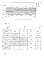
- Fig. 2 1 shows a security element 3 with a carrier layer 31, an adhesion promoter layer 32, a transparent layer 33, an adhesion promoter layer 34, a pattern layer 35 and an adhesive layer 36.
- the carrier layer 31 is preferably a transparent plastic film having a thickness between 12 ⁇ m and 250 ⁇ m, preferably between 19 ⁇ m and 120 ⁇ m (12 ⁇ m to 23 ⁇ m for banknotes, 20 ⁇ m to 120 ⁇ m for ID documents).
- the plastic film here preferably consists of PET, BOPP, OPP, PC, PEN or Mylar® (polyethylene terephthalate polyester film from DuPont).
- the upper side of the carrier layer 31 may additionally have protective layers.
- the adhesion promoter layers 32 and 34 have a layer thickness of 20 nm to 5 microns. With a suitable choice of material of the carrier layer 31, the transparent layer 33 and the pattern layer 35, the adhesion promoter layers 32 and 34 could also be dispensed with. Furthermore, the adhesion promoter layers 32 and 34 are preferably also used as barrier layers that protect the transparent layer 33 from environmental influences protect, which could cause a subsequent swelling or shrinkage of the transparent layer 33 and thus a change in the optical properties of the transparent layer 33. This barrier layer 34 can also be subsequently applied after the exposure of the volume hologram.
- a release layer may also be provided.
- the transparent layer 33 is a layer with non-homogeneous, spatially dependent refractive index, whereby a multiplicity of Bragg planes are formed by refractive index variation in the transparent layer 33 due to this three-dimensional refractive index pattern.
- the transparent layer 33 has a layer thickness between 5 .mu.m and 200 .mu.m, more preferably a layer thickness of 20 .mu.m and 100 .mu.m. In this case, the layer thickness influences the number of Bragg planes formed in the transparent layer 33 and thus influences the optical effect generated by the transparent layer 33.
- the transparent layer 33 on a plurality of zones 41 which are arranged according to a grid in a sequence adjacent to each other.
- the zones 41 are in the embodiment according to Fig. 2 arranged in a regular, two-dimensional grid, which is defined by two vectors standing at right angles to each other.
- the raster widths along the one vector and the other vector are preferably chosen to be smaller than 300 ⁇ m, more preferably smaller than 100 ⁇ m.
- the screen widths along the one vector are different from the screen widths along the other vector.
- the raster width is smaller than 300 ⁇ m for at least one of the vectors.
- the zones 41 follow one another only in one direction and thus the zones thus have, for example, a width of 200 ⁇ m and a length of several mm. This is also the case with a 1 D moire.
- the masters 1 and 2 are arranged on both sides of the film body 3 'with the photopolymer layer 33'.
- the film body 3 ' is placed for example in a stop-and-go operation between two flat master or even in continuous operation between two trained as exposure rollers master 1 and 2 arranged.
- the master 1 is designed as a master acting in transmission and the master 2 as a master acting in reflection.
- the master 1 has layers 11 and 12, between which a surface structure 13 is formed.
- the layers 11 and 12 are made of different materials that are in their optical refractive index differ by more than 0.2, preferably by more than 0.5.
- the materials used for the HRI or LRI layers are preferably inorganic materials, for example MgF 2 , Si x O y , TiO 2 , ZnS. In this case, it is also possible that the layers 11 and 12 are made of the same material or consist of materials having substantially the same refractive index. It is also possible that the layer 11 is missing. Then the master is bordering on air.
- the master 2 has a layer 21 and a layer 22.
- the layer 21 is a transparent layer in the region of the wavelength used for the exposure.
- the layer 22 is a reflection layer, preferably a metallic reflection layer.
- a surface structure 23 is formed, which forms the boundary layer between the layer 21 and 22.
- the surface structures 13 and 23 are binary surface structures whose structural elements are nearly rectangular and whose structure depth is in the range of 100 nm to 1000 nm.
- the spacing of the structural elements of the surface structures 13 and 14 is in the range between 50 and 1000 nm, preferably between 100 nm and 300 nm.
- the surface structures 13 and 14 formed in the master 1 and in the master 2 are arranged in register with one another and as one another formed inverse surface structures. This is for example in Fig. 1 shown where it can be seen that the surface structure 23 corresponds to the surface structure 13 mirrored on the surface of the photopolymer layer 33 '.
- the surface structures 13 and 23 are aligned in register with the zones 41. As in Fig.
- the surface structures 13 and 23 are formed as a symmetrical structure to the center line of the respective zone 41, wherein the spacing of the structural elements as well as the width of the structural elements decreases starting from the center of the zones 41 to the boundary line of the respective zone 41 with the adjacent zone. Furthermore, it is also possible that the surface structures 13 and 23 are each formed point-symmetrically to the center of the zones 41.
- the layers 12 and 21 of the first master and second master also serve as a spacer layer, so that the first master facing top of the photopolymer layer 33 'a distance 46 from the surface structure 13 and the master 2 facing bottom of the photopolymer layer 33' a Distance 47 from the surface structure 23 has.
- the distance 46 preferably has a value of 10 ⁇ m to 200 ⁇ m and the distance 47 has a value of 0 ⁇ m to 100 ⁇ m.
- liquids may also be used, e.g. Oil, glycerine or water.
- the layers 12 and 21 have a refractive index which is nearly equal or only slightly different (e.g., 0.2 to 0.5) to the refractive index of the photopolymer layer 33 '.
- a light beam of a corresponding suitable light source such as a Lasers, expanded to a suitable thickness and so the in Fig. 1 generated waveform generated.
- the expanded light beam passes through the master 1 arranged between the photopolymer layer 33 'and the light source, is deflected by the master 1 according to the surface structure 3, passes through the photopolymer layer 33' and is diffracted back and forth by the surface structure 23 molded into the reflection layer 22 corresponding to the surface structure 23 then again passes through the photopolymer layer 33 '.
- an interference pattern formed by the superimposition of these light beams is thus formed, which forms a corresponding three-dimensional pattern with regions of different refractive index in the photopolymer layer 33'.
- the photopolymer material of the photopolymer layer 33 ' is polymerized and cured by, for example, irradiation with UV light or by electron beam.
- the adhesion promoter layer 34 and the pattern layer 35 are applied to the thus formed transparent layer 33.
- the primer layer or barrier layer 34 and then the adhesive layer may be applied.
- the film is then applied to the pattern layer 35.
- the pattern layer 35 consists of one or more layers, which are partially formed and form pattern areas 43 and background areas 44, which differ in their optical properties.
- the pattern layer 35 has a plurality of zones 42 with a smallest dimension of less than 300 ⁇ m, which are arranged adjacent to one another according to a grid in a one- or two-dimensional sequence and each have a pattern area 43 and a background area 44 that form an encoding.
- the pattern of the pattern layer 35 may be formed as described above for the pattern of the transparent layer 33.
- the codings formed by the pattern areas 43 and background areas 44 in the zones 42 are preferably identical codings, it is however, it is also possible that the codes in adjacent zones 42 differ.
- the pattern layer 35 is a partially metallized layer, wherein the metal of the metal layer is provided in the pattern areas 43 and is not provided in the background areas 44.
- the different optical properties of the pattern layer 35 are achieved by different reflection properties, different colors or different optically variable effects in the pattern areas 43 and the background areas 44.
- the adhesive layer 36 is applied to the pattern layer 35, preferably in a layer thickness between 0.5 ⁇ m and 4 ⁇ m.
- the Bragg planes of the transparent layer are formed into different transmissive imaging functions.
- the coding of the regions 42 is selected to be identical in this exemplary embodiment, and the grid width of the grid of the transparent layer 33 and of the pattern layer 35 differs from 0 ⁇ m to 15 ⁇ m.
- the pattern layer 35 and the transparent layer 33 are part of a laminate, for example an ID card.
- the pattern layer 35 is applied to a substrate and the substrate with a provided transparent layer and then the transparent layer 33 (optionally with the layers 31 and 32) by means of an adhesive layer register exactly to the pattern layer 35 on the transparent layer or the pattern layer 35 fixed.
- a protective layer in particular a plastic film is placed on the film body thus formed and then laminated in a laminater of the resulting film body, for example, to an ID card.
- the transparent layer 33 is applied to one side of a transparent carrier substrate and the pattern layer 35 is applied to the other side of the carrier substrate.
- the carrier is preferably the carrier of a banknote which is transparent at least in the region in which the transparent layer 33 is applied, for example a polymer banknote around the carrier.
- the transparent layer 33 is applied to a bendable or foldable carrier substrate and the pattern layer 35 is applied to another area of the carrier substrate.
- the transparent layer 33 and the pattern layer 35 can then be brought into coincidence, whereby then an optically variable effect is visible.
- the carrier substrate is also formed transparent and the transparent layer 33 on the one hand and the pattern layer 35 on the other hand applied on opposite sides of the carrier substrate.
Landscapes
- Physics & Mathematics (AREA)
- Engineering & Computer Science (AREA)
- Manufacturing & Machinery (AREA)
- General Physics & Mathematics (AREA)
- Optics & Photonics (AREA)
- Chemical Kinetics & Catalysis (AREA)
- Chemical & Material Sciences (AREA)
- General Chemical & Material Sciences (AREA)
- Business, Economics & Management (AREA)
- Accounting & Taxation (AREA)
- Finance (AREA)
- Credit Cards Or The Like (AREA)
- Diffracting Gratings Or Hologram Optical Elements (AREA)
Applications Claiming Priority (1)
| Application Number | Priority Date | Filing Date | Title |
|---|---|---|---|
| DE102009004251A DE102009004251B3 (de) | 2009-01-07 | 2009-01-07 | Sicherheitselement sowie Verfahren zur Herstellung eines Sicherheitselements |
Publications (1)
| Publication Number | Publication Date |
|---|---|
| EP2207051A1 true EP2207051A1 (fr) | 2010-07-14 |
Family
ID=41682374
Family Applications (1)
| Application Number | Title | Priority Date | Filing Date |
|---|---|---|---|
| EP09016065A Withdrawn EP2207051A1 (fr) | 2009-01-07 | 2009-12-23 | Elément de sécurité ainsi que procédé destiné à la fabrication d'un support d'éléments de sécurité |
Country Status (4)
| Country | Link |
|---|---|
| US (1) | US8562026B2 (fr) |
| EP (1) | EP2207051A1 (fr) |
| JP (1) | JP5674087B2 (fr) |
| DE (1) | DE102009004251B3 (fr) |
Families Citing this family (2)
| Publication number | Priority date | Publication date | Assignee | Title |
|---|---|---|---|---|
| DE102006026099B8 (de) * | 2006-06-03 | 2008-05-29 | MAX-PLANCK-Gesellschaft zur Förderung der Wissenschaften e.V. | Insektenschutzfolie |
| CN107466382B (zh) * | 2015-06-26 | 2020-12-22 | 费德欧尼公司 | 具有图案与双侧全息效果的安全元件 |
Citations (4)
| Publication number | Priority date | Publication date | Assignee | Title |
|---|---|---|---|---|
| US6060143A (en) * | 1996-11-14 | 2000-05-09 | Ovd Kinegram Ag | Optical information carrier |
| EP1091267A2 (fr) | 1999-10-08 | 2001-04-11 | Dai Nippon Printing Co., Ltd. | Stratifié avec hologramme en relief et étiquette permettant de préparer un tel stratifié avec hologramme en relief |
| DE102006029536A1 (de) * | 2006-06-26 | 2007-12-27 | Ovd Kinegram Ag | Mehrschichtkörper mit Mikrolinsen |
| US20080037131A1 (en) * | 2003-11-21 | 2008-02-14 | Nanoventions, Inc. | Micro-optic security and image presentation system |
Family Cites Families (6)
| Publication number | Priority date | Publication date | Assignee | Title |
|---|---|---|---|---|
| JP3722310B2 (ja) * | 1996-05-17 | 2005-11-30 | 大日本印刷株式会社 | ホログラム記録媒体の作製方法 |
| US5986781A (en) * | 1996-10-28 | 1999-11-16 | Pacific Holographics, Inc. | Apparatus and method for generating diffractive element using liquid crystal display |
| US6572975B2 (en) * | 2001-08-24 | 2003-06-03 | General Electric Company | Optically coated article and method for its preparation |
| JP2003139957A (ja) * | 2001-10-31 | 2003-05-14 | Sharp Corp | 位相型体積ホログラム光学素子の製造方法 |
| DE102007023560B4 (de) * | 2007-05-21 | 2009-02-05 | Ovd Kinegram Ag | Mehrschichtkörper |
| US8415691B2 (en) * | 2008-08-18 | 2013-04-09 | Tsmc Solid State Lighting Ltd. | Omnidirectional reflector |
-
2009
- 2009-01-07 DE DE102009004251A patent/DE102009004251B3/de not_active Expired - Fee Related
- 2009-12-23 EP EP09016065A patent/EP2207051A1/fr not_active Withdrawn
-
2010
- 2010-01-06 JP JP2010001531A patent/JP5674087B2/ja not_active Expired - Fee Related
- 2010-01-06 US US12/683,167 patent/US8562026B2/en active Active
Patent Citations (4)
| Publication number | Priority date | Publication date | Assignee | Title |
|---|---|---|---|---|
| US6060143A (en) * | 1996-11-14 | 2000-05-09 | Ovd Kinegram Ag | Optical information carrier |
| EP1091267A2 (fr) | 1999-10-08 | 2001-04-11 | Dai Nippon Printing Co., Ltd. | Stratifié avec hologramme en relief et étiquette permettant de préparer un tel stratifié avec hologramme en relief |
| US20080037131A1 (en) * | 2003-11-21 | 2008-02-14 | Nanoventions, Inc. | Micro-optic security and image presentation system |
| DE102006029536A1 (de) * | 2006-06-26 | 2007-12-27 | Ovd Kinegram Ag | Mehrschichtkörper mit Mikrolinsen |
Non-Patent Citations (1)
| Title |
|---|
| JOUBERT C ET AL: "Holographic optical components for high brightness single-LCD projectors", PROCEEDINGS OF THE SPIE - THE INTERNATIONAL SOCIETY FOR OPTICAL ENGINEERING, SPIE, US, vol. 3013, 1 January 1997 (1997-01-01), pages 98 - 106, XP007912459, ISSN: 0277-786X * |
Also Published As
| Publication number | Publication date |
|---|---|
| JP2010188720A (ja) | 2010-09-02 |
| JP5674087B2 (ja) | 2015-02-25 |
| US8562026B2 (en) | 2013-10-22 |
| DE102009004251B3 (de) | 2010-07-01 |
| US20100173133A1 (en) | 2010-07-08 |
Similar Documents
| Publication | Publication Date | Title |
|---|---|---|
| EP1797539B1 (fr) | Document de securite a fenetres transparentes | |
| EP2451650B1 (fr) | Corps multicouche | |
| EP2475529B1 (fr) | Corps multicouche | |
| EP3216620B1 (fr) | Élement de securite, document de valeur dote d'un tel element de securite ainsi que procede de fabrication d'un element de securite | |
| EP1853763B2 (fr) | Element de securite et procede de production de cet element | |
| EP2002310B1 (fr) | Procédé de fabrication d'un corps multicouches avec hologramme volumique, et élément de sécurité | |
| EP2225110B1 (fr) | Élément de sécurité | |
| DE102007023560B4 (de) | Mehrschichtkörper | |
| EP1636737B1 (fr) | Element de securite optique | |
| EP2200841B1 (fr) | Corps multicouche et procédé pour fabriquer un corps multicouche | |
| EP2164711B1 (fr) | Système de représentation | |
| EP2040934B1 (fr) | Élément de sécurité | |
| EP1800271B1 (fr) | Document de securite | |
| EP2331343B1 (fr) | Dispositif de représentation | |
| EP1713645B2 (fr) | Grille-image comprenant plusieurs champs de grille | |
| EP1644871B1 (fr) | Element de securite optique et systeme de visualisation d'informations cachees | |
| EP2853411B1 (fr) | Élément de sécurité avec image lenticulaire | |
| EP2385902B1 (fr) | Élément de sécurité et papier de sécurité | |
| EP2934904B1 (fr) | Élément de sécurité avec une image lenticulaire | |
| EP2874820B1 (fr) | Élément de sécurité pour papiers de sécurité, documents fiduciaires ou similaires | |
| EP2727742B1 (fr) | Elément de sécurité avec image lenticulaire | |
| DE10036505A1 (de) | Optisch wirksame Struktur zur Personalisierung von Karten u. dgl., sowie Verfahren zu deren Herstellung | |
| EP3034315B1 (fr) | Élement de securite, son procede de fabrication et support de donnees dote d'un element de securite | |
| DE102017106433A1 (de) | Sicherheitselement und Verfahren zur Herstellung eines Sicherheitselements | |
| DE102009004251B3 (de) | Sicherheitselement sowie Verfahren zur Herstellung eines Sicherheitselements |
Legal Events
| Date | Code | Title | Description |
|---|---|---|---|
| PUAI | Public reference made under article 153(3) epc to a published international application that has entered the european phase |
Free format text: ORIGINAL CODE: 0009012 |
|
| AK | Designated contracting states |
Kind code of ref document: A1 Designated state(s): AT BE BG CH CY CZ DE DK EE ES FI FR GB GR HR HU IE IS IT LI LT LU LV MC MK MT NL NO PL PT RO SE SI SK SM TR |
|
| AX | Request for extension of the european patent |
Extension state: AL BA RS |
|
| 17P | Request for examination filed |
Effective date: 20110111 |
|
| 17Q | First examination report despatched |
Effective date: 20110920 |
|
| STAA | Information on the status of an ep patent application or granted ep patent |
Free format text: STATUS: THE APPLICATION IS DEEMED TO BE WITHDRAWN |
|
| 18D | Application deemed to be withdrawn |
Effective date: 20120131 |