EP2206962A2 - Contrôle d'injection tardive à mélange pauvre - Google Patents
Contrôle d'injection tardive à mélange pauvre Download PDFInfo
- Publication number
- EP2206962A2 EP2206962A2 EP09180047A EP09180047A EP2206962A2 EP 2206962 A2 EP2206962 A2 EP 2206962A2 EP 09180047 A EP09180047 A EP 09180047A EP 09180047 A EP09180047 A EP 09180047A EP 2206962 A2 EP2206962 A2 EP 2206962A2
- Authority
- EP
- European Patent Office
- Prior art keywords
- fuel
- transition zone
- interior
- combustor
- gas turbine
- Prior art date
- Legal status (The legal status is an assumption and is not a legal conclusion. Google has not performed a legal analysis and makes no representation as to the accuracy of the status listed.)
- Withdrawn
Links
Images


Classifications
-
- F—MECHANICAL ENGINEERING; LIGHTING; HEATING; WEAPONS; BLASTING
- F23—COMBUSTION APPARATUS; COMBUSTION PROCESSES
- F23R—GENERATING COMBUSTION PRODUCTS OF HIGH PRESSURE OR HIGH VELOCITY, e.g. GAS-TURBINE COMBUSTION CHAMBERS
- F23R3/00—Continuous combustion chambers using liquid or gaseous fuel
- F23R3/28—Continuous combustion chambers using liquid or gaseous fuel characterised by the fuel supply
- F23R3/34—Feeding into different combustion zones
- F23R3/346—Feeding into different combustion zones for staged combustion
-
- F—MECHANICAL ENGINEERING; LIGHTING; HEATING; WEAPONS; BLASTING
- F02—COMBUSTION ENGINES; HOT-GAS OR COMBUSTION-PRODUCT ENGINE PLANTS
- F02C—GAS-TURBINE PLANTS; AIR INTAKES FOR JET-PROPULSION PLANTS; CONTROLLING FUEL SUPPLY IN AIR-BREATHING JET-PROPULSION PLANTS
- F02C7/00—Features, components parts, details or accessories, not provided for in, or of interest apart form groups F02C1/00 - F02C6/00; Air intakes for jet-propulsion plants
- F02C7/22—Fuel supply systems
- F02C7/228—Dividing fuel between various burners
-
- F—MECHANICAL ENGINEERING; LIGHTING; HEATING; WEAPONS; BLASTING
- F02—COMBUSTION ENGINES; HOT-GAS OR COMBUSTION-PRODUCT ENGINE PLANTS
- F02C—GAS-TURBINE PLANTS; AIR INTAKES FOR JET-PROPULSION PLANTS; CONTROLLING FUEL SUPPLY IN AIR-BREATHING JET-PROPULSION PLANTS
- F02C9/00—Controlling gas-turbine plants; Controlling fuel supply in air- breathing jet-propulsion plants
- F02C9/26—Control of fuel supply
- F02C9/28—Regulating systems responsive to plant or ambient parameters, e.g. temperature, pressure, rotor speed
Definitions
- Various aspects of the present invention are directed to late lean injection (LLI) fuel staging configurations and methods of achieving the same.
- LLI late lean injection
- One temperature controlling method involves the premixing of fuel and air to form a lean mixture thereof prior to combustion.
- the required temperatures of the combustion products are so high that the combustor must be operated with peak gas temperatures in the reaction zone that exceed the thermal NOx formation threshold temperature, resulting in significant NOx formation.
- a gas turbine engine includes a combustor having a first interior in which a first fuel supplied thereto by a fuel circuit is combustible, a turbine, including rotating turbine blades, into which products of at least the combustion of the first fuel are receivable to power the rotation of the turbine blades, a transition zone, including a second interior in which a second fuel supplied thereto by the fuel circuit and the products of the combustion of the first fuel are combustible, the transition zone being disposed to fluidly couple the combustor and the turbine to one another, a plurality of fuel injectors, which are structurally supported by the transition zone and coupled to the fuel circuit, and which are configured to supply the second fuel to the second interior in any one of a single axial stage, multiple axial stages, a single axial circumferential stage and multiple axial circumferential stages, and a control system coupled to the fuel circuit and configured to control relative amounts of the first and second fuels supplied by the fuel circuit to the first and second interior
- a gas turbine engine including a combustor having a first interior in which a first fuel supplied thereto by a fuel circuit is combustible and a turbine, including rotating turbine blades, into which products of at least the combustion of the first fuel are receivable to power the rotation of the turbine blades is provided and includes a transition zone, including a second interior in which a second fuel supplied thereto by the fuel circuit and the products of the combustion of the first fuel are combustible, the transition zone being disposed to fluidly couple the combustor and the turbine to one another, a plurality of fuel injectors, which are structurally supported by the transition zone and coupled to the fuel circuit, and which are configured to supply the second fuel to the second interior in any one of a single axial stage, multiple axial stages, a single axial circumferential stage and multiple axial circumferential stages, and a control system coupled to the fuel circuit and configured to control relative amounts of the first and second fuels supplied by the fuel circuit to the first and second interior
- a method of operating a gas turbine engine in which a turbine is fluidly coupled to a combustor by a transition zone interposed therebetween includes supplying a first fuel to a first interior within the combustor, combusting the first fuel in the first interior within the combustor, supplying a second fuel to a second interior within the transition zone in any one of a single axial stage, multiple axial stages, a single axial circumferential stage and multiple axial circumferential stages, combusting the second fuel and a stream of combustion products, received from the first interior, in the second interior within the transition zone, and controlling relative amounts of the first and second fuels supplied to the first and second interiors.
- a gas turbine engine 10 includes a combustor 20 having a first interior 21 in which a first fuel supplied thereto by fuel circuit 70 is combustible, a compressor 30 by which inlet air is compressed and provided to at least the combustor 20 and a transition zone 43 and a turbine 50, including rotating turbine blades, into which products of at least the combustion of the first fuel are receivable to power a rotation of the turbine blades.
- the transition zone 43 is disposed to fluidly couple the combustor 20 and the turbine 50 and includes a second interior 41 in which a second fuel supplied thereto by the fuel circuit 70 and the products of the combustion of the first fuel are combustible.
- the combustor 20 and the transition zone 43 combine with one another to generally have a form of a head end 11, which may have various configurations, as will be discussed below.
- the head end 11 may include multiple premixing nozzles 12.
- FIGS. 4A-4D other head end 11 configurations are possible.
- Such alternate configurations include, but are not limited to, the standard combustor configuration 13 of FIG. 4A , the Dry Low NOx (DLN) 1+ combustor configuration 14 of FIG. 4B , the DLN 2+ combustor configuration 15 of FIG. 4C and the DLN 2.6/2.6+ combustor configuration 16 of FIG. 4D .
- Still other combustor configurations include Integrated Gasification Combined Cycle (IGCC) head ends, catalytic head ends, diffusion style head ends and Multi-Nozzle Quiet Combustion (MNQC) style head ends.
- IGCC Integrated Gasification Combined Cycle
- MNQC Multi-Nozzle Quiet Combustion
- versions of the configurations may be late lean injection (LLI) compatible.
- LLI compatible combustor is any combustor with either an exit temperature that exceeds 2500° F or handles fuels with components that are more reactive than methane with a hot side residence time greater than 10 ms.
- an LLI compatible version of the DLN 1+ combustor configuration 14 may have an exit temperature that is less than 2500° F but may handle fuels with components that are more reactive than methane.
- An LLI compatible version of a diffusion style head end combustor may have exit temperatures in excess of 2500° F and may handle fuels with components that are more reactive than methane.
- an LLI compatible version of the DLN 2.0/DLN 2+ combustor configuration 15 may have an exit temperature in excess of 2500° F and may handle fuels with components that are more reactive than methane while an LLI compatible version of catalytic head ends or the DLN 2.6/2.6+ combustor configuration 16 may have an exit temperature in excess of 2500° F and may handle fuels with components more reactive than methane.
- a plurality of fuel injectors 60 are each structurally supported by an exterior wall of the transition zone 43 or by an exterior wall of a sleeve 40 around the transition zone 43 and extend into the second interior 41 to varying depths.
- the fuel injectors 60 are each configured to provide LLI fuel staging capability. That is, the fuel injectors 60 are each configured to supply the second fuel (i.e., LLI fuel) to the second interior 41 by, e.g., fuel injection in a direction that is generally transverse to a predominant flow direction through the transition zone 43, in any one of a single axial stage, multiple axial stages, a single axial circumferential stage and multiple axial circumferential stages. In so doing, conditions within the combustor 20 and the transition zone 43 are staged to create local zones of stable combustion.
- LLI fuel second fuel
- the fuel injectors 60 can have various features and functionalities.
- the fuel injectors 60 can include a tube-in-tube injector configuration 125. In this configuration, fuel is actively fed to the interior 41 of the transition zone 43 through a nozzle in a tube 130 and air is passively fed through an annular space between the tube 130 and the sleeve 145 which extends from the impingement sleeve surface 140 to the interface part 150.
- the fuel injectors 60 can also include swirl injectors 155.
- fuel injector 60 In this configuration, fuel is actively fed to the interior 41 of the transition zone 43 through a manifold 160 and air is passively fed through a central purge 165 and/or by way of a swirler 170.
- other examples of fuel injector 60 configurations include a rich catalytic injector configuration 175, which includes rich catalytic elements 180, and multi-tube/showerhead injector configurations 185, which include multiple tubes 190 through which fuel is fed to the transition zone 43.
- the fuel injectors 60 can be coupled to the transition zone 43 at locations that correspond to pre-existing dilution holes 42, if any, on the outer surface of the transition zone 43.
- fuel injectors 60 may be placed as required on the exterior of the transition zone 43.
- the single axial stage includes a currently operating single fuel injector 60
- the multiple axial stages there is no antecedent basis for multiple here include multiple currently operating fuel injectors 60, which are respectively disposed at multiple axial locations of the transition zone 43
- the single axial circumferential stage includes multiple currently operating fuel injectors 60 respectively disposed around a circumference of a single axial location of the transition zone 43
- the multiple axial circumferential stages include multiple currently operating fuel injectors 60, which are disposed around a circumference of the transition zone 43 at multiple axial locations thereof.
- the fuel injectors 60 may be spaced substantially evenly or unevenly from one another.
- eight or ten fuel injectors 60 may be employed at a particular circumferential stage with 2, 3, 4 or 5 fuel injectors 60 installed with varying degrees of separation from one another on northern and southern hemispheres of the transition zone 43.
- the fuel injectors 60 may be in-line and/or staggered with respect to one another.
- each of the fuel injectors 60 may be jointly or separately activated or deactivated so as to form the currently effective one of the single axial stage, the multiple axial stages, the single axial circumferential stage and the multiple axial circumferential stages.
- the fuel injectors 60 may each be supplied with LLI fuel by way of the fuel circuit 70 via a valve 61 disposed between a corresponding fuel injector 60 and a branch 71 or 72 of the fuel circuit 70.
- the valve 61 signal communicates with a controller 80 that sends a signal to the valve 61 that causes the valve 61 to open or close and to thereby activate or deactivate the corresponding fuel injector 60.
- the controller 80 signals to each of the valves 61 to open and thereby activate each of the fuel injectors 60.
- the controller 80 signals to each of the valves 61 corresponding to only the fuel injectors 60 of the single axial circumferential stage to open and thereby activate each of the fuel injectors 60.
- this control system is merely exemplary and it is understood that multiple combinations of fuel injector configurations are possible and that other systems and methods for controlling at least one of the activation and deactivation of the fuel injectors 60 are available.
- the controller 80 may be further configured to activate only those fuel injectors 60 having certain fuel injector configurations at any one time.
- the controller 80 signals to each of the valves 61 corresponding to those fuel injectors 60 to open.
- the controller 80 signals to each of the valves 61 corresponding to only the fuel injectors 60 including swirl injectors 155 to open.
- a method of operating a gas turbine engine 10, in which a turbine 50 is fluidly coupled to a combustor 20 by a transition zone 43 interposed therebetween includes supplying a first fuel to a first interior 21 within the combustor 20, combusting the first fuel in the first interior 21 within the combustor 20, supplying a second fuel to a second interior 41 within the transition zone 43 in any one of a single axial stage, multiple axial stages, a single axial circumferential stage and multiple axial circumferential stages, and combusting the second fuel and a stream of combustion products, received from the first interior 21, in the second interior 41 within the transition zone.
- the supplying of the second fuel to the second interior 41 in the single axial stage includes activating a single fuel injector 60
- the supplying of the second fuel to the second interior 41 in the multiple axial stages includes activating multiple fuel injectors 60 respectively disposed at multiple axial locations of the transition zone 43
- the supplying of the second fuel to the second interior 41 in the single axial circumferential stage includes activating multiple fuel injectors 60 respectively disposed around a circumference of the transition zone 43 at a single axial location thereof
- the supplying of the second fuel to the second interior 41 in the multiple axial circumferential stages includes activating multiple fuel injectors 60 respectively disposed around a circumference of the transition zone 43 at multiple axial locations thereof.
- FIG. 2 provides a graphical illustration of various options for fuel split controls.
- a percentage of a head end fuel split is plotted against a Tfire value, which is a measurement of a temperature within the combustor 20 and/or the transition zone 43.
- the controller 80 is further configured to control a flow direction of the first and second fuels toward the head end 11 and/or the fuel injectors 60, it is seen that LLI fuel staging can also be further controlled by the controller 80 in accordance with the control options shown in FIG. 2 .
- the controller 80 is coupled to the valves 61, as discussed above, and the valve 73 to control the delivery of the second fuel to the fuel injectors 60 and to control the delivery of the first and/or the LLI fuel to the head end 11.
- a first option for such control is to employ a fixed head end split in which a percentage ( ⁇ 100%) of the first and/or the LLI fuel is delivered to the transition zone 43 for LLI fuel staging once a preselected value of Tfire is achieved. From that point, the percentage of the fuel delivered to the transition zone 43 remains substantially constant.
- a second option is to employ a head end split schedule. In this case, the percentage of LLI fuel increases proportionally, or in accordance with some other suitable function, as the value of Tfire increases beyond a preselected value.
- a third option is to make the percentage of the LLI fuel a function of any one or more of several characteristics of the interior environments of the combustor 20, the compressor 30, the transition zone 43 and/or the turbine 50.
- the percentage could be made a function of Tcd or Pcd, which are measured compressor discharge temperature and pressure conditions, humidity readings from within the combustor 20, the compressor 30 or the transition zone 43, gas turbine exhaust temperature and/or T39, which is a calculated combustor exit temperature.
- the third option discussed above may also be modified to account for a current Modified Wobbe Index (MWI).
- MWI Modified Wobbe Index
- the MWI measures energy density of fuel and that, for a given fuel nozzle area, a lower MWI indicates increased pressure ratios across the head end fuel nozzles that can cause undesirable dynamics to which LLI fuel nozzles are insensitive
- the percentage of the LLI fuel could also be made a function of the MWI. This way, as the MWI increases, a larger percentage of LLI fuel is diverted to the transition zone 43.
- thermocouples/pressure gauges 100 may be installed within the combustor 20, the compressor 30, the transition zone 43 and/or the turbine 50 as is deemed necessary to measure temperatures and pressures within the combustor 20, the compressor 30, the transition zone 43 and the turbine 50.
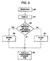
- a method of controlling a turbine with LLI capability includes operating the turbine 300, initiating the LLI 310 after a certain period of time or once a preselected value of Tfire is achieved, and, in accordance with the first option, continuing to operate the LLI at the same level 350. Conversely, in accordance with the second option, the method includes continuing to operate the LLI at an increasing level 350. Meanwhile, in accordance with the third option, it is determined whether any particular measured characteristics of the combustor 20, the compressor 30 and/or the transition zone 43 are elevated or lower than established parameters 320 and, based on a result of the determining, the LLI level is decreased 330, increased 340 or maintained and, subsequently, the LLI operation is continued 350.
- the controller 80 is further configured to control the 3-way valve 110 and, in some embodiments, an additional valve disposed on a manifold around the fuel injectors 60 or, as mentioned above, the valves 61.
- the controller 80 is able to control the air split of the inlet air delivered by the compressor 30 to the combustor 20 and the transition zone 43 or to each fuel injector 60.
- the controller 80 is able to modify fuel splits and air splits simultaneously.
- the controller 80 can thereby create operational paths for a combustion system that respect optimal fuel to air ratios of the combustion system.
- the 3-way valve 110 could be further integrated as a part of an overall air coolant system, extended turndown efforts and/or Department of Energy (DoE) programs.
- DoE Department of Energy
- the control of the 3-way valve 110 is accomplished in order to optimize fuel to air ratios of the combustion system. These ratios may be preselected as being based on specifications for the combustor 20 and the transition zone 43 or may be based on current environmental conditions.
- the controller 80 could increase the fuel to air ratio in either the combustor 20 or the transition zone 43 based on temperature and/or pressure readings generated by the thermocouples/pressure gauges 100 installed within the combustor 20, the compressor 30, the transition zone 43 and the turbine 50.
- Late Lean Injection can also allow for an injection of multiple gas streams, including alternate gases, such as refinery gases, into the transition zone 43 that non-LLI combustors are generally unable to handle.
- Highly reactive gases such as refinery gases
- refinery gases typically cannot be handled by premixed combustors due to the concern for undesirable flameholding in the premixers.
- Refinery gases which may or may not be blended with natural gases can, in certain cases, be injected directly into the transition zone 43 without such problems, especially where the fuel injectors 60 are tolerant of flameholding.
- the amounts of the natural gases used can be a function of Tcd, Pcd, and T39, as described above.
- flameholding sensitive premixers can be employed at the head end 11 to prevent or substantially reduce the likelihood of flameholding incidents.
- the alternate gases can be injected from source 90 into a branch 71 or 72 of the fuel circuit 70 via a refinery gas valve 91 that is controlled by controller 80.
- the controller 80 can open the refinery gas valve 91 such that the alternate gases can propagate through the fuel circuit 70 toward the fuel injectors 61.
- the alternate gases can be blended with natural gases to form the first fuel in compositions that reflect tolerances of the particular head end 11 in use.
- the alternate gases can be provided with or without such blending to form the second fuel.
- the alternate gases may include refinery gases that are received by the fuel circuit 70 from the source 90, as mentioned above, and gases consisting of components that are more reactive than methane. More particularly, the alternate gases may include gases that contain a quantity of above about 0.5% by volume of hydrogen, a quantity of above about 5% by volume of ethane, a quantity of above about 10% by volume of propane, a quantity of above about 5% by volume of butane or a hydrocarbon above butane.
- the fuel circuit 70 may also incorporate multiple branches 71 and 72 to accommodate for changes in fuel flow.
- the multiple branches 71 and 72 can then also be used to allow for large changes in fuel composition by affording additional fuel flow area or by introducing the fuel in a way that creates separate modes of combustion (i.e. diffusion and premixing).
- the branches 71 and 72 can also allow for variations in fuel wobbe number, fuel composition and for dynamic tuning.
- the branches 71 and 72 of the fuel circuit 70 can be embodied as braches of the fuel circuit 70, as additional fuel nozzles in the transition zone 43 or a combination of these options as well as other suitable options.
- the branches 71 and 72 may further include a catalytic partial oxidation reactor (CPCR) 120 disposed along lengths thereof.
- CPCR 120 converts methane within the first or second fuels to hydrogen and/or partially oxidizes the methane without creating nitrogen oxides.
- the fuel can be injected into the transition zone 43 even later than it otherwise would be.
Landscapes
- Engineering & Computer Science (AREA)
- Chemical & Material Sciences (AREA)
- Combustion & Propulsion (AREA)
- Mechanical Engineering (AREA)
- General Engineering & Computer Science (AREA)
Applications Claiming Priority (1)
| Application Number | Priority Date | Filing Date | Title |
|---|---|---|---|
| US12/349,869 US8683808B2 (en) | 2009-01-07 | 2009-01-07 | Late lean injection control strategy |
Publications (2)
| Publication Number | Publication Date |
|---|---|
| EP2206962A2 true EP2206962A2 (fr) | 2010-07-14 |
| EP2206962A3 EP2206962A3 (fr) | 2012-04-25 |
Family
ID=42101986
Family Applications (1)
| Application Number | Title | Priority Date | Filing Date |
|---|---|---|---|
| EP09180047A Withdrawn EP2206962A3 (fr) | 2009-01-07 | 2009-12-18 | Contrôle d'injection tardive à mélange pauvre |
Country Status (4)
| Country | Link |
|---|---|
| US (1) | US8683808B2 (fr) |
| EP (1) | EP2206962A3 (fr) |
| JP (1) | JP2010159954A (fr) |
| CN (1) | CN101776016A (fr) |
Cited By (1)
| Publication number | Priority date | Publication date | Assignee | Title |
|---|---|---|---|---|
| US8887506B2 (en) | 2012-05-11 | 2014-11-18 | General Electric Company | Fuel injector with mixing circuit |
Families Citing this family (48)
| Publication number | Priority date | Publication date | Assignee | Title |
|---|---|---|---|---|
| US8112216B2 (en) | 2009-01-07 | 2012-02-07 | General Electric Company | Late lean injection with adjustable air splits |
| US9354618B2 (en) | 2009-05-08 | 2016-05-31 | Gas Turbine Efficiency Sweden Ab | Automated tuning of multiple fuel gas turbine combustion systems |
| US9671797B2 (en) | 2009-05-08 | 2017-06-06 | Gas Turbine Efficiency Sweden Ab | Optimization of gas turbine combustion systems low load performance on simple cycle and heat recovery steam generator applications |
| US8437941B2 (en) * | 2009-05-08 | 2013-05-07 | Gas Turbine Efficiency Sweden Ab | Automated tuning of gas turbine combustion systems |
| US9267443B2 (en) | 2009-05-08 | 2016-02-23 | Gas Turbine Efficiency Sweden Ab | Automated tuning of gas turbine combustion systems |
| US8601820B2 (en) | 2011-06-06 | 2013-12-10 | General Electric Company | Integrated late lean injection on a combustion liner and late lean injection sleeve assembly |
| US8407892B2 (en) | 2011-08-05 | 2013-04-02 | General Electric Company | Methods relating to integrating late lean injection into combustion turbine engines |
| US9010120B2 (en) | 2011-08-05 | 2015-04-21 | General Electric Company | Assemblies and apparatus related to integrating late lean injection into combustion turbine engines |
| US8904796B2 (en) * | 2011-10-19 | 2014-12-09 | General Electric Company | Flashback resistant tubes for late lean injector and method for forming the tubes |
| US9181876B2 (en) | 2012-01-04 | 2015-11-10 | General Electric Company | Method and apparatus for operating a gas turbine engine |
| US9140455B2 (en) | 2012-01-04 | 2015-09-22 | General Electric Company | Flowsleeve of a turbomachine component |
| US9243507B2 (en) | 2012-01-09 | 2016-01-26 | General Electric Company | Late lean injection system transition piece |
| US20130277447A1 (en) * | 2012-04-23 | 2013-10-24 | General Electric Company | Method and system to control a fuel injector |
| US9310078B2 (en) | 2012-10-31 | 2016-04-12 | General Electric Company | Fuel injection assemblies in combustion turbine engines |
| US9291098B2 (en) | 2012-11-14 | 2016-03-22 | General Electric Company | Turbomachine and staged combustion system of a turbomachine |
| US9551492B2 (en) * | 2012-11-30 | 2017-01-24 | General Electric Company | Gas turbine engine system and an associated method thereof |
| US9279369B2 (en) * | 2013-03-13 | 2016-03-08 | General Electric Company | Turbomachine with transition piece having dilution holes and fuel injection system coupled to transition piece |
| US9435541B2 (en) | 2013-03-15 | 2016-09-06 | General Electric Company | Systems and apparatus relating to downstream fuel and air injection in gas turbines |
| US9714768B2 (en) | 2013-03-15 | 2017-07-25 | General Electric Company | Systems and apparatus relating to downstream fuel and air injection in gas turbines |
| US9528439B2 (en) | 2013-03-15 | 2016-12-27 | General Electric Company | Systems and apparatus relating to downstream fuel and air injection in gas turbines |
| US9482434B2 (en) | 2013-03-15 | 2016-11-01 | General Electric Company | Methods relating to downstream fuel and air injection in gas turbines |
| EP2789915A1 (fr) * | 2013-04-10 | 2014-10-15 | Alstom Technology Ltd | Procédé de fonctionnement d'une chambre de combustion et chambre de combustion |
| US20150075170A1 (en) * | 2013-09-17 | 2015-03-19 | General Electric Company | Method and system for augmenting the detection reliability of secondary flame detectors in a gas turbine |
| GB201317175D0 (en) | 2013-09-27 | 2013-11-06 | Rolls Royce Plc | An apparatus and a method of controlling the supply of fuel to a combustion chamber |
| US20150107255A1 (en) * | 2013-10-18 | 2015-04-23 | General Electric Company | Turbomachine combustor having an externally fueled late lean injection (lli) system |
| US20150159877A1 (en) * | 2013-12-06 | 2015-06-11 | General Electric Company | Late lean injection manifold mixing system |
| US9528705B2 (en) * | 2014-04-08 | 2016-12-27 | General Electric Company | Trapped vortex fuel injector and method for manufacture |
| US9803555B2 (en) * | 2014-04-23 | 2017-10-31 | General Electric Company | Fuel delivery system with moveably attached fuel tube |
| JP6437018B2 (ja) * | 2014-06-26 | 2018-12-12 | シーメンス エナジー インコーポレイテッド | 排気再循環を伴う軸方向段構造燃焼システム |
| US10480792B2 (en) * | 2015-03-06 | 2019-11-19 | General Electric Company | Fuel staging in a gas turbine engine |
| US20160281992A1 (en) * | 2015-03-24 | 2016-09-29 | General Electric Company | Injection boss for a unibody combustor |
| US9995221B2 (en) | 2015-12-22 | 2018-06-12 | General Electric Company | Staged fuel and air injection in combustion systems of gas turbines |
| US9938903B2 (en) | 2015-12-22 | 2018-04-10 | General Electric Company | Staged fuel and air injection in combustion systems of gas turbines |
| US9976487B2 (en) * | 2015-12-22 | 2018-05-22 | General Electric Company | Staged fuel and air injection in combustion systems of gas turbines |
| US9989260B2 (en) | 2015-12-22 | 2018-06-05 | General Electric Company | Staged fuel and air injection in combustion systems of gas turbines |
| US20170176012A1 (en) | 2015-12-22 | 2017-06-22 | General Electric Company | Fuel injectors and staged fuel injection systems in gas turbines |
| US9945562B2 (en) | 2015-12-22 | 2018-04-17 | General Electric Company | Staged fuel and air injection in combustion systems of gas turbines |
| US9945294B2 (en) * | 2015-12-22 | 2018-04-17 | General Electric Company | Staged fuel and air injection in combustion systems of gas turbines |
| US20180135531A1 (en) * | 2016-11-15 | 2018-05-17 | General Electric Company | Auto-thermal valve for passively controlling fuel flow to axial fuel stage of gas turbine |
| JP7214332B2 (ja) * | 2017-01-18 | 2023-01-30 | ゼネラル・エレクトリック・カンパニイ | ガスタービンの燃焼システムにおける段階的な燃料および空気噴射 |
| EP3351855B1 (fr) | 2017-01-19 | 2020-04-22 | General Electric Company | Injection étagée d'air et de combustible dans des systèmes de combustion de turbines à gaz |
| US11242806B2 (en) | 2017-11-20 | 2022-02-08 | Power Systems Mfg., Llc | Method of controlling fuel injection in a reheat combustor for a combustor unit of a gas turbine |
| US11384940B2 (en) * | 2019-01-23 | 2022-07-12 | General Electric Company | Gas turbine load/unload path control |
| US11174792B2 (en) | 2019-05-21 | 2021-11-16 | General Electric Company | System and method for high frequency acoustic dampers with baffles |
| US11156164B2 (en) | 2019-05-21 | 2021-10-26 | General Electric Company | System and method for high frequency accoustic dampers with caps |
| US11404879B2 (en) * | 2020-03-05 | 2022-08-02 | General Electric Company | Systems and methods for improved rate of change of frequency ride-through in electric power systems |
| US11566790B1 (en) * | 2021-10-28 | 2023-01-31 | General Electric Company | Methods of operating a turbomachine combustor on hydrogen |
| US11578871B1 (en) * | 2022-01-28 | 2023-02-14 | General Electric Company | Gas turbine engine combustor with primary and secondary fuel injectors |
Family Cites Families (37)
| Publication number | Priority date | Publication date | Assignee | Title |
|---|---|---|---|---|
| US3045425A (en) * | 1954-03-03 | 1962-07-24 | Snecma | Exhaust reheat equipment for gasturbine engines |
| GB881935A (en) | 1959-09-28 | 1961-11-08 | Gen Electric | Fuel injector for a combustion chamber |
| DE2232025A1 (de) | 1972-06-30 | 1974-01-17 | Motoren Turbinen Union | Gasturbinenanlage, insbesondere triebwerk mit gleichraumverbrennung |
| US4735052A (en) * | 1985-09-30 | 1988-04-05 | Kabushiki Kaisha Toshiba | Gas turbine apparatus |
| JPS62174539A (ja) * | 1985-09-30 | 1987-07-31 | Toshiba Corp | ガスタ−ビン制御装置 |
| US5163284A (en) | 1991-02-07 | 1992-11-17 | Sundstrand Corporation | Dual zone combustor fuel injection |
| US5235804A (en) | 1991-05-15 | 1993-08-17 | United Technologies Corporation | Method and system for combusting hydrocarbon fuels with low pollutant emissions by controllably extracting heat from the catalytic oxidation stage |
| JP2950720B2 (ja) * | 1994-02-24 | 1999-09-20 | 株式会社東芝 | ガスタービン燃焼装置およびその燃焼制御方法 |
| DE4416650A1 (de) * | 1994-05-11 | 1995-11-16 | Abb Management Ag | Verbrennungsverfahren für atmosphärische Feuerungsanlagen |
| US5943866A (en) | 1994-10-03 | 1999-08-31 | General Electric Company | Dynamically uncoupled low NOx combustor having multiple premixers with axial staging |
| US5974781A (en) | 1995-12-26 | 1999-11-02 | General Electric Company | Hybrid can-annular combustor for axial staging in low NOx combustors |
| US6201029B1 (en) | 1996-02-13 | 2001-03-13 | Marathon Oil Company | Staged combustion of a low heating value fuel gas for driving a gas turbine |
| US6047550A (en) | 1996-05-02 | 2000-04-11 | General Electric Co. | Premixing dry low NOx emissions combustor with lean direct injection of gas fuel |
| US5901547A (en) * | 1996-06-03 | 1999-05-11 | Air Products And Chemicals, Inc. | Operation method for integrated gasification combined cycle power generation system |
| US6105359A (en) | 1997-03-31 | 2000-08-22 | Wilson; Michael A. | Efficiency enhanced turbine engine |
| FR2774152B1 (fr) | 1998-01-28 | 2000-03-24 | Inst Francais Du Petrole | Chambre de combustion de turbine a gaz fonctionnant au carburant liquide |
| GB0019533D0 (en) | 2000-08-10 | 2000-09-27 | Rolls Royce Plc | A combustion chamber |
| US6868676B1 (en) | 2002-12-20 | 2005-03-22 | General Electric Company | Turbine containing system and an injector therefor |
| US7284378B2 (en) | 2004-06-04 | 2007-10-23 | General Electric Company | Methods and apparatus for low emission gas turbine energy generation |
| AU2003289368A1 (en) | 2003-12-16 | 2005-07-05 | Hitachi, Ltd. | Combustor for gas turbine |
| US7973016B2 (en) * | 2004-01-23 | 2011-07-05 | Joslin Diebetes Center | Methods of treating, reducing, or preventing autoimmune conditions |
| US7010921B2 (en) | 2004-06-01 | 2006-03-14 | General Electric Company | Method and apparatus for cooling combustor liner and transition piece of a gas turbine |
| US7269939B2 (en) | 2004-11-24 | 2007-09-18 | General Electric Company | Method and apparatus for automatically actuating fuel trim valves in a gas |
| US7395670B1 (en) | 2005-02-18 | 2008-07-08 | Praxair Technology, Inc. | Gas turbine fuel preparation and introduction method |
| US8529646B2 (en) | 2006-05-01 | 2013-09-10 | Lpp Combustion Llc | Integrated system and method for production and vaporization of liquid hydrocarbon fuels for combustion |
| JP4831820B2 (ja) * | 2006-05-22 | 2011-12-07 | 三菱重工業株式会社 | ガスタービン出力学習回路及びこれを備えたガスタービンの燃焼制御装置 |
| US20070277530A1 (en) | 2006-05-31 | 2007-12-06 | Constantin Alexandru Dinu | Inlet flow conditioner for gas turbine engine fuel nozzle |
| US8141370B2 (en) | 2006-08-08 | 2012-03-27 | General Electric Company | Methods and apparatus for radially compliant component mounting |
| US7810333B2 (en) | 2006-10-02 | 2010-10-12 | General Electric Company | Method and apparatus for operating a turbine engine |
| US7690188B2 (en) | 2007-03-02 | 2010-04-06 | United Technologies Corporation | Combination engines for aircraft |
| US7886545B2 (en) * | 2007-04-27 | 2011-02-15 | General Electric Company | Methods and systems to facilitate reducing NOx emissions in combustion systems |
| US8387398B2 (en) * | 2007-09-14 | 2013-03-05 | Siemens Energy, Inc. | Apparatus and method for controlling the secondary injection of fuel |
| US7886539B2 (en) | 2007-09-14 | 2011-02-15 | Siemens Energy, Inc. | Multi-stage axial combustion system |
| US8397512B2 (en) | 2008-08-25 | 2013-03-19 | General Electric Company | Flow device for turbine engine and method of assembling same |
| US8113000B2 (en) | 2008-09-15 | 2012-02-14 | Siemens Energy, Inc. | Flashback resistant pre-mixer assembly |
| US8272218B2 (en) | 2008-09-24 | 2012-09-25 | Siemens Energy, Inc. | Spiral cooled fuel nozzle |
| US9822649B2 (en) * | 2008-11-12 | 2017-11-21 | General Electric Company | Integrated combustor and stage 1 nozzle in a gas turbine and method |
-
2009
- 2009-01-07 US US12/349,869 patent/US8683808B2/en active Active
- 2009-12-18 EP EP09180047A patent/EP2206962A3/fr not_active Withdrawn
- 2009-12-28 JP JP2009296994A patent/JP2010159954A/ja not_active Withdrawn
-
2010
- 2010-01-07 CN CN201010003966A patent/CN101776016A/zh active Pending
Non-Patent Citations (1)
| Title |
|---|
| None |
Cited By (1)
| Publication number | Priority date | Publication date | Assignee | Title |
|---|---|---|---|---|
| US8887506B2 (en) | 2012-05-11 | 2014-11-18 | General Electric Company | Fuel injector with mixing circuit |
Also Published As
| Publication number | Publication date |
|---|---|
| US20100170219A1 (en) | 2010-07-08 |
| EP2206962A3 (fr) | 2012-04-25 |
| US8683808B2 (en) | 2014-04-01 |
| JP2010159954A (ja) | 2010-07-22 |
| CN101776016A (zh) | 2010-07-14 |
Similar Documents
| Publication | Publication Date | Title |
|---|---|---|
| US8457861B2 (en) | Late lean injection with adjustable air splits | |
| US8701382B2 (en) | Late lean injection with expanded fuel flexibility | |
| US8683808B2 (en) | Late lean injection control strategy | |
| US8701418B2 (en) | Late lean injection for fuel flexibility | |
| US8701383B2 (en) | Late lean injection system configuration | |
| US8707707B2 (en) | Late lean injection fuel staging configurations | |
| EP2206964A2 (fr) | Configurations d'injecteur de combustible pour injection tardive pauvre | |
| US9638423B2 (en) | Multifuel gas turbine combustor with fuel mixing chamber and supplemental burner | |
| JP2010159956A5 (fr) | ||
| EP2309189B1 (fr) | Chambre de combustion à faible NOx pour carburant contenant de l'hydrogène et son fonctionnement |
Legal Events
| Date | Code | Title | Description |
|---|---|---|---|
| PUAI | Public reference made under article 153(3) epc to a published international application that has entered the european phase |
Free format text: ORIGINAL CODE: 0009012 |
|
| AK | Designated contracting states |
Kind code of ref document: A2 Designated state(s): AT BE BG CH CY CZ DE DK EE ES FI FR GB GR HR HU IE IS IT LI LT LU LV MC MK MT NL NO PL PT RO SE SI SK SM TR |
|
| AX | Request for extension of the european patent |
Extension state: AL BA RS |
|
| PUAL | Search report despatched |
Free format text: ORIGINAL CODE: 0009013 |
|
| AK | Designated contracting states |
Kind code of ref document: A3 Designated state(s): AT BE BG CH CY CZ DE DK EE ES FI FR GB GR HR HU IE IS IT LI LT LU LV MC MK MT NL NO PL PT RO SE SI SK SM TR |
|
| AX | Request for extension of the european patent |
Extension state: AL BA RS |
|
| RIC1 | Information provided on ipc code assigned before grant |
Ipc: F02C 9/28 20060101ALI20120321BHEP Ipc: F02C 7/228 20060101ALI20120321BHEP Ipc: F23R 3/34 20060101AFI20120321BHEP |
|
| 17P | Request for examination filed |
Effective date: 20121025 |
|
| 17Q | First examination report despatched |
Effective date: 20130306 |
|
| STAA | Information on the status of an ep patent application or granted ep patent |
Free format text: STATUS: THE APPLICATION IS DEEMED TO BE WITHDRAWN |
|
| 18D | Application deemed to be withdrawn |
Effective date: 20130917 |