EP2206894A1 - Steam turbine having exhaust enthalpic condition control and related method - Google Patents
Steam turbine having exhaust enthalpic condition control and related method Download PDFInfo
- Publication number
- EP2206894A1 EP2206894A1 EP10150264A EP10150264A EP2206894A1 EP 2206894 A1 EP2206894 A1 EP 2206894A1 EP 10150264 A EP10150264 A EP 10150264A EP 10150264 A EP10150264 A EP 10150264A EP 2206894 A1 EP2206894 A1 EP 2206894A1
- Authority
- EP
- European Patent Office
- Prior art keywords
- steam
- exhaust
- steam turbine
- enthalpic
- turbine
- Prior art date
- Legal status (The legal status is an assumption and is not a legal conclusion. Google has not performed a legal analysis and makes no representation as to the accuracy of the status listed.)
- Withdrawn
Links
Images

Classifications
-
- F—MECHANICAL ENGINEERING; LIGHTING; HEATING; WEAPONS; BLASTING
- F01—MACHINES OR ENGINES IN GENERAL; ENGINE PLANTS IN GENERAL; STEAM ENGINES
- F01K—STEAM ENGINE PLANTS; STEAM ACCUMULATORS; ENGINE PLANTS NOT OTHERWISE PROVIDED FOR; ENGINES USING SPECIAL WORKING FLUIDS OR CYCLES
- F01K17/00—Using steam or condensate extracted or exhausted from steam engine plant
- F01K17/02—Using steam or condensate extracted or exhausted from steam engine plant for heating purposes, e.g. industrial, domestic
-
- Y—GENERAL TAGGING OF NEW TECHNOLOGICAL DEVELOPMENTS; GENERAL TAGGING OF CROSS-SECTIONAL TECHNOLOGIES SPANNING OVER SEVERAL SECTIONS OF THE IPC; TECHNICAL SUBJECTS COVERED BY FORMER USPC CROSS-REFERENCE ART COLLECTIONS [XRACs] AND DIGESTS
- Y02—TECHNOLOGIES OR APPLICATIONS FOR MITIGATION OR ADAPTATION AGAINST CLIMATE CHANGE
- Y02E—REDUCTION OF GREENHOUSE GAS [GHG] EMISSIONS, RELATED TO ENERGY GENERATION, TRANSMISSION OR DISTRIBUTION
- Y02E20/00—Combustion technologies with mitigation potential
- Y02E20/14—Combined heat and power generation [CHP]
Definitions
- the invention relates generally to turbine technology. More particularly, the invention relates to a steam turbine having exhaust enthalpic condition control and a related method.
- a condensing steam turbine exhausts steam in a partly condensed state, while in a non-condensing steam turbine steam is pulled from various locations and used for other industrial applications such as preheating water boilers, etc.
- Valves may control steam extracted from a non-condensing steam turbine.
- Non-condensing steam turbines are typically used in industrial applications where there is a need to have steam at specific pressure and temperature conditions for other industrial applications. Extraction points can be located at any point in the steam path that provides the necessary steam conditions.
- a first aspect of the disclosure provides a steam turbine comprising: a casing including a steam inlet and an exhaust, the casing enclosing operative structure of the steam turbine; a valve controlling introduction of a steam flow at a location of the steam turbine to impact an enthalpic condition of steam exiting the exhaust; and a controller controlling operation of the valve to attain a desired enthalpic condition of steam exiting the exhaust.
- a second aspect of the disclosure provides a method comprising: providing a steam turbine having a casing including a steam inlet and an exhaust, the casing enclosing operative structure of the steam turbine; and controlling operation of a valve that controls introduction of a steam flow at a location of the steam turbine that impacts an enthalpic condition of steam exiting the exhaust to attain a desired enthalpic condition of the steam exiting the exhaust.
- FIG. 1 shows a schematic block diagram illustrating embodiments of a steam turbine 100 having exhaust enthalpic control provided by a valve 102 that controls a steam flow 104, i.e., from a source of steam.
- Valve 102 operation is controlled via a controller 106.
- Controller 106 may be a stand alone controller, or it may be part of an overall steam turbine controller 108.
- Steam turbine 100 may include any now known or later developed steam turbine that includes a casing 120 including a steam inlet 122 and an exhaust 124 (two shown). Steam turbine 100 is designed with a specific turbine efficiency to achieve either wet (percentage moisture) or dry (degrees of superheat) exhaust 124 conditions.
- casing 120 encloses operative structure of the steam turbine such as a rotor, rotating blades, vanes, etc., that are acted upon by steam entering through steam inlet 122.
- Exhaust(s) 124 allows egress of used steam from casing 120, and may each include appropriate control, isolation and relief valves 126 controlled by turbine controller 108 in a known fashion.
- Steam turbine 100 may be a condensing type turbine, or as illustrated, may be of the non-condensing type, including at least one extraction point 128 at which steam is extracted from casing 120. Despite illustration of extraction point(s) 128 as on casing 120, they can be located at any point in the steam path. As understood, steam taken from extraction point(s) 128 may be used in another industrial application 130. Another industrial application 140 is also shown to which steam from exhaust 124 generated according to teachings of embodiments of the invention may be applied. Industrial applications 130 and 140 each may include any now known or later developed process that may use steam at the respective conditions provided from extraction point(s) 128 for industrial application 130 and from exhaust 124 for industrial application 140.
- extraction point(s) 128 may be different than that (140) to which steam from exhaust 124 is delivered, and may require steam having different enthalpic conditions).
- a non-exhaustive list of industrial applications may include a de-salination process, district heating, a lower pressure turbine, a boiler, etc.
- Appropriate conduit(s) 132, 134 may be provided for delivering the steam exiting extraction point(s) 128 and/or exhaust 124 to industrial application 130, 140, respectively.
- Valve 102 controls introduction of steam flow 104 at a location 150 of steam turbine 100 to impact enthalpic conditions of steam exiting exhaust(s) 124.
- a steam turbine needed to be designed to provide the particular enthalpic conditions at the exhaust. Consequently, each application of the steam turbine required specific modifications of the steam turbine structure to achieve the desired enthalpic conditions, which is cumbersome and expensive.
- controller 106 controls operation of valve 102 to attain a desired enthalpic condition of steam exiting exhaust(s) 124.
- Different industrial applications 140 can thus be provided with steam from exhaust 124 of steam turbine 100 without modifying the structure of steam turbine 100.
- Steam flow 104 can be originated in a number of ways.
- steam flow 104 may be originated from an extraction point 128 (via dashed conduit) where steam turbine includes them. In this case, extraction of steam may be controlled by a valve 140.
- steam flow 104 may be generated from any other source, e.g., another boiler separate from that for steam turbine 100.
- location 150 at which steam flow 104 is introduced to the steam path of steam turbine 100 may vary.
- the location of introduction of steam flow 104 is positioned at exhaust 124 (i.e., at exhaust 124 or a position directly downstream therefrom).
- location 150 may be positioned at a point along casing 120. That is, steam flow 104 is introduced into the operative structure of steam turbine 100 such as at a particular stage of rotating blade (not shown).
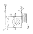
- location 150 in FIG. 2 is shown as two points, it is understood that the location may include only one entry point. Further, although two example locations have been illustrated, it is understood that location 150 could be at different positions than that shown along the steam path.
- steam turbine 100 In operation, steam turbine 100 is provided and operation of valve 102 that controls introduction of steam flow 104 at a location of the steam turbine that impacts an enthalpic condition of steam exiting the exhaust is controlled to attain a desired enthalpic condition of the steam exiting the exhaust. That is, steam flow 104 has the appropriate fundamental enthalpic conditions such that when an appropriate volume of steam flow 104 is combined with whatever steam exists at location 150 at which it is introduced into the steam path of steam turbine 100, it results in steam at exhaust 124 having a desired enthalpic condition for an industrial application 140. Controller 106 may access appropriate, well-known sensors for determining the enthalpic conditions of steam flow 104 and the steam at exhaust 124.
- Controller 106 may further include appropriate logic for comparison of enthalpic conditions of steam at exhaust 124 and steam flow 104 and for calculating appropriate volumes of steam flow 104 to introduce into location 150 to achieve the desired enthalpic conditions for the exhaust steam.
- the logic required is considered well within the purview of one with ordinary skill in the art to program, and will not be described further.
- a throttling valve 160 may also be positioned downstream from exhaust 124 to increase the exhaust enthalpy by increasing exhaust pressure (shorten the expansion line).
- first,” “second,” and the like, herein do not denote any order, quantity, or importance, but rather are used to distinguish one element from another, and the terms “a” and “an” herein do not denote a limitation of quantity, but rather denote the presence of at least one of the referenced item.
- the modifier “about” used in connection with a quantity is inclusive of the stated value and has the meaning dictated by the context, (e.g., includes the degree of error associated with measurement of the particular quantity).
- suffix "(s)” as used herein is intended to include both the singular and the plural of the term that it modifies, thereby including one or more of that term (e.g., the metal(s) includes one or more metals).
- Ranges disclosed herein are inclusive and independently combinable (e.g., ranges of "up to about 25 wt%, or, more specifically, about 5 wt% to about 20 wt %", is inclusive of the endpoints and all intermediate values of the ranges of "about 5 wt% to about 25 wt%,” etc).
Landscapes
- Engineering & Computer Science (AREA)
- Chemical & Material Sciences (AREA)
- Combustion & Propulsion (AREA)
- Mechanical Engineering (AREA)
- General Engineering & Computer Science (AREA)
- Control Of Turbines (AREA)
Abstract
A steam turbine (100) includes a casing (120) including a steam inlet (122) and an exhaust (124), the casing (120) enclosing operative structure of the steam turbine (100); a valve (102) controlling introduction of a steam flow (104) at a location (150) of the steam turbine (100) to impact an enthalpic condition of steam exiting the exhaust (124); and a controller (106) controlling operation of the valve (102) to attain a desired enthalpic condition of steam exiting the exhaust (124). Controlling operation of the valve (102) allows for attainment of a desired enthalpic condition of the steam exiting the exhaust (124) for use in another industrial process without having to modify the steam turbine (100) structure.
Description
- The invention relates generally to turbine technology. More particularly, the invention relates to a steam turbine having exhaust enthalpic condition control and a related method.
- Two types of steam turbines used in industry are a condensing steam turbine and a non-condensing steam turbine. A condensing steam turbine exhausts steam in a partly condensed state, while in a non-condensing steam turbine steam is pulled from various locations and used for other industrial applications such as preheating water boilers, etc. Valves may control steam extracted from a non-condensing steam turbine. Non-condensing steam turbines are typically used in industrial applications where there is a need to have steam at specific pressure and temperature conditions for other industrial applications. Extraction points can be located at any point in the steam path that provides the necessary steam conditions.
- Steam for industrial applications can be obtained from turbine extractions or from the turbine exhaust. Steam condition requirements vary from one customer to the other. Consequently, each steam turbine may require specific modifications of the steam turbine structure to achieve the desired enthalpic conditions for the exhaust, which is cumbersome and expensive. Since there are only so many models of steam turbine that a manufacturer can reasonably produce, there may be instances where use of exhaust steam for other industrial applications may not be possible while still meeting other requirements for the steam turbine.
- A first aspect of the disclosure provides a steam turbine comprising: a casing including a steam inlet and an exhaust, the casing enclosing operative structure of the steam turbine; a valve controlling introduction of a steam flow at a location of the steam turbine to impact an enthalpic condition of steam exiting the exhaust; and a controller controlling operation of the valve to attain a desired enthalpic condition of steam exiting the exhaust.
- A second aspect of the disclosure provides a method comprising: providing a steam turbine having a casing including a steam inlet and an exhaust, the casing enclosing operative structure of the steam turbine; and controlling operation of a valve that controls introduction of a steam flow at a location of the steam turbine that impacts an enthalpic condition of steam exiting the exhaust to attain a desired enthalpic condition of the steam exiting the exhaust.
- There follows a detailed description of embodiments of the invention by way of example only with reference to the accompanying drawings, in which:
-
FIG. 1 shows a schematic block diagram illustrating embodiments of a steam turbine having exhaust enthalpic control; and -
FIG. 2 shows a schematic block diagram illustrating alternative embodiments of a steam turbine having exhaust enthalpic control. - Referring to the drawings,
FIG. 1 shows a schematic block diagram illustrating embodiments of asteam turbine 100 having exhaust enthalpic control provided by avalve 102 that controls asteam flow 104, i.e., from a source of steam. Valve 102 operation is controlled via acontroller 106.Controller 106 may be a stand alone controller, or it may be part of an overallsteam turbine controller 108. -
Steam turbine 100 may include any now known or later developed steam turbine that includes acasing 120 including asteam inlet 122 and an exhaust 124 (two shown).Steam turbine 100 is designed with a specific turbine efficiency to achieve either wet (percentage moisture) or dry (degrees of superheat)exhaust 124 conditions. As understood,casing 120 encloses operative structure of the steam turbine such as a rotor, rotating blades, vanes, etc., that are acted upon by steam entering throughsteam inlet 122. Exhaust(s) 124 allows egress of used steam fromcasing 120, and may each include appropriate control, isolation andrelief valves 126 controlled byturbine controller 108 in a known fashion. -
Steam turbine 100 may be a condensing type turbine, or as illustrated, may be of the non-condensing type, including at least oneextraction point 128 at which steam is extracted fromcasing 120. Despite illustration of extraction point(s) 128 as oncasing 120, they can be located at any point in the steam path. As understood, steam taken from extraction point(s) 128 may be used in anotherindustrial application 130. Anotherindustrial application 140 is also shown to which steam fromexhaust 124 generated according to teachings of embodiments of the invention may be applied.Industrial applications industrial application 130 and fromexhaust 124 forindustrial application 140. (Note that theindustrial application 130 to which extracted steam is delivered, where extraction point(s) 128 are provided, may be different than that (140) to which steam fromexhaust 124 is delivered, and may require steam having different enthalpic conditions). A non-exhaustive list of industrial applications may include a de-salination process, district heating, a lower pressure turbine, a boiler, etc. Appropriate conduit(s) 132, 134 may be provided for delivering the steam exiting extraction point(s) 128 and/orexhaust 124 toindustrial application - Valve 102 controls introduction of
steam flow 104 at alocation 150 ofsteam turbine 100 to impact enthalpic conditions of steam exiting exhaust(s) 124. Conventionally, in order for steam exiting throughexhaust 124 to be applied to anotherindustrial application 140, a steam turbine needed to be designed to provide the particular enthalpic conditions at the exhaust. Consequently, each application of the steam turbine required specific modifications of the steam turbine structure to achieve the desired enthalpic conditions, which is cumbersome and expensive. In accordance with embodiments of the invention, however,controller 106 controls operation ofvalve 102 to attain a desired enthalpic condition of steam exiting exhaust(s) 124. Differentindustrial applications 140 can thus be provided with steam fromexhaust 124 ofsteam turbine 100 without modifying the structure ofsteam turbine 100. -
Steam flow 104 can be originated in a number of ways. InFIG. 1 ,steam flow 104 may be originated from an extraction point 128 (via dashed conduit) where steam turbine includes them. In this case, extraction of steam may be controlled by avalve 140. However,steam flow 104 may be generated from any other source, e.g., another boiler separate from that forsteam turbine 100. - As shown in the figures,
location 150 at whichsteam flow 104 is introduced to the steam path ofsteam turbine 100 may vary. In one embodiment, shown inFIG. 1 , the location of introduction ofsteam flow 104 is positioned at exhaust 124 (i.e., atexhaust 124 or a position directly downstream therefrom). Alternatively, as shown inFIG. 2 ,location 150 may be positioned at a point alongcasing 120. That is,steam flow 104 is introduced into the operative structure ofsteam turbine 100 such as at a particular stage of rotating blade (not shown). Althoughlocation 150 inFIG. 2 is shown as two points, it is understood that the location may include only one entry point. Further, although two example locations have been illustrated, it is understood thatlocation 150 could be at different positions than that shown along the steam path. - In operation,
steam turbine 100 is provided and operation ofvalve 102 that controls introduction ofsteam flow 104 at a location of the steam turbine that impacts an enthalpic condition of steam exiting the exhaust is controlled to attain a desired enthalpic condition of the steam exiting the exhaust. That is,steam flow 104 has the appropriate fundamental enthalpic conditions such that when an appropriate volume ofsteam flow 104 is combined with whatever steam exists atlocation 150 at which it is introduced into the steam path ofsteam turbine 100, it results in steam atexhaust 124 having a desired enthalpic condition for anindustrial application 140.Controller 106 may access appropriate, well-known sensors for determining the enthalpic conditions ofsteam flow 104 and the steam atexhaust 124.Controller 106 may further include appropriate logic for comparison of enthalpic conditions of steam atexhaust 124 andsteam flow 104 and for calculating appropriate volumes ofsteam flow 104 to introduce intolocation 150 to achieve the desired enthalpic conditions for the exhaust steam. The logic required is considered well within the purview of one with ordinary skill in the art to program, and will not be described further. - In an optional embodiment, shown in
FIG. 2 , athrottling valve 160 may also be positioned downstream fromexhaust 124 to increase the exhaust enthalpy by increasing exhaust pressure (shorten the expansion line). - The terms "first," "second," and the like, herein do not denote any order, quantity, or importance, but rather are used to distinguish one element from another, and the terms "a" and "an" herein do not denote a limitation of quantity, but rather denote the presence of at least one of the referenced item. The modifier "about" used in connection with a quantity is inclusive of the stated value and has the meaning dictated by the context, (e.g., includes the degree of error associated with measurement of the particular quantity). The suffix "(s)" as used herein is intended to include both the singular and the plural of the term that it modifies, thereby including one or more of that term (e.g., the metal(s) includes one or more metals). Ranges disclosed herein are inclusive and independently combinable (e.g., ranges of "up to about 25 wt%, or, more specifically, about 5 wt% to about 20 wt %", is inclusive of the endpoints and all intermediate values of the ranges of "about 5 wt% to about 25 wt%," etc).
- While various embodiments are described herein, it will be appreciated from the specification that various combinations of elements, variations or improvements therein may be made by those skilled in the art, and are within the scope of the invention. In addition, many modifications may be made to adapt a particular situation or material to the teachings of the invention without departing from essential scope thereof. Therefore, it is intended that the invention not be limited to the particular embodiment disclosed as the best mode contemplated for carrying out this invention, but that the invention will include all embodiments falling within the scope of the appended claims.
Claims (15)
- A steam turbine (100) comprising:a casing (120) including a steam inlet (122) and an exhaust (124), the casing (120) enclosing operative structure of the steam turbine (100);a valve (102) controlling introduction of a steam flow (104) at a location (150) of the steam turbine (100) to impact an enthalpic condition of steam exiting the exhaust (124); anda controller (106) controlling operation of the valve (102) to attain a desired enthalpic condition of steam exiting the exhaust (124).
- The steam turbine of claim 1, wherein the location (150) is positioned at the exhaust (124).
- The steam turbine of claim 1, wherein the location (150) is positioned at a point along the casing (120).
- The steam turbine of any of the preceding claims, further comprising at least one extraction point (128) at which steam is extracted from the casing (120).
- The steam turbine of claim 4, wherein the steam flow (104) originates from the at least one extraction point (128).
- The steam turbine of any of the preceding claims, wherein the controller (106) is part of a controller (106) for the steam turbine (100).
- The steam turbine of any of the preceding claims, further comprising a conduit for delivering the steam exiting the exhaust (124) to an industrial application (130, 140).
- The steam turbine of any of the preceding claims, further comprising a throttling valve (160) (102) downstream from the exhaust (124).
- A method comprising:providing a steam turbine (100) having a casing (120) including a steam inlet (122) and an exhaust (124), the casing (120) enclosing operative structure of the steam turbine (100); andcontrolling operation of a valve (102) that controls introduction of a steam flow (104) at a location (150) of the steam turbine (100) that impacts an enthalpic condition of steam exiting the exhaust (124) to attain a desired enthalpic condition of the steam exiting the exhaust (124).
- The method of claim 9, wherein the location (150) is positioned at the exhaust (124).
- The method of claim 9, wherein the location (150) is positioned at a point along the casing (120).
- The method of any of claims 9 to 11, further comprising extracting steam from at least one extraction point (128) from the casing (120).
- The method of claim 12, wherein the steam flow (104) originates from the at least one extraction point (128).
- The method of any of claims 9 to 13, wherein the controlling is performed by a controller (106) for the steam turbine (100).
- The method of any of claims 9 to 14, further comprising delivering the steam exiting the exhaust (124) to an industrial application (130, 140).
Applications Claiming Priority (1)
| Application Number | Priority Date | Filing Date | Title |
|---|---|---|---|
| US12/352,044 US8186935B2 (en) | 2009-01-12 | 2009-01-12 | Steam turbine having exhaust enthalpic condition control and related method |
Publications (1)
| Publication Number | Publication Date |
|---|---|
| EP2206894A1 true EP2206894A1 (en) | 2010-07-14 |
Family
ID=42044396
Family Applications (1)
| Application Number | Title | Priority Date | Filing Date |
|---|---|---|---|
| EP10150264A Withdrawn EP2206894A1 (en) | 2009-01-12 | 2010-01-07 | Steam turbine having exhaust enthalpic condition control and related method |
Country Status (4)
| Country | Link |
|---|---|
| US (1) | US8186935B2 (en) |
| EP (1) | EP2206894A1 (en) |
| JP (1) | JP2010159763A (en) |
| RU (1) | RU2010100114A (en) |
Cited By (1)
| Publication number | Priority date | Publication date | Assignee | Title |
|---|---|---|---|---|
| EP2447484A1 (en) * | 2010-10-29 | 2012-05-02 | Siemens Aktiengesellschaft | Steam turbine assembly with variable steam supply |
Families Citing this family (13)
| Publication number | Priority date | Publication date | Assignee | Title |
|---|---|---|---|---|
| US9587522B2 (en) * | 2014-02-06 | 2017-03-07 | General Electric Company | Model-based partial letdown thrust balancing |
| US12291982B2 (en) | 2020-11-30 | 2025-05-06 | Rondo Energy, Inc. | Thermal energy storage systems for use in material processing |
| US12018596B2 (en) | 2020-11-30 | 2024-06-25 | Rondo Energy, Inc. | Thermal energy storage system coupled with thermal power cycle systems |
| US12146424B2 (en) | 2020-11-30 | 2024-11-19 | Rondo Energy, Inc. | Thermal energy storage system coupled with a solid oxide electrolysis system |
| US11913361B2 (en) | 2020-11-30 | 2024-02-27 | Rondo Energy, Inc. | Energy storage system and alumina calcination applications |
| US11913362B2 (en) | 2020-11-30 | 2024-02-27 | Rondo Energy, Inc. | Thermal energy storage system coupled with steam cracking system |
| US12359591B1 (en) | 2020-11-30 | 2025-07-15 | Rondo Energy, Inc. | Thermal energy storage systems for repowering existing power plants for improving efficiency and safety |
| MA71196B1 (en) | 2020-11-30 | 2025-04-30 | Rondo Energy, Inc. | ENERGY STORAGE SYSTEM AND APPLICATIONS |
| IE20250101U1 (en) | 2023-04-14 | 2025-10-22 | Rondo Energy Inc | Thermal energy storage blocks and associated support structures |
| WO2025226989A2 (en) | 2024-04-24 | 2025-10-30 | Rondo Energy, Inc. | Thermal energy storage system for simple and combined cycle power generation |
| WO2025245498A1 (en) | 2024-05-24 | 2025-11-27 | Rondo Energy, Inc. | Thermal energy storage system with high efficiency heater control |
| US12566034B1 (en) | 2024-07-02 | 2026-03-03 | Rondo Energy, Inc. | Thermal energy storage system coupled to a heat exchanger with thermal protection |
| US12607170B2 (en) | 2024-07-12 | 2026-04-21 | Rondo Energy, Inc. | Thermal energy storage system for use with a low temperature heat source and a thermal power cycle system |
Citations (6)
| Publication number | Priority date | Publication date | Assignee | Title |
|---|---|---|---|---|
| GB1062303A (en) * | 1965-02-08 | 1967-03-22 | Gen Electric Co Ltd | Improvements in or relating to turbines |
| JPS5465203A (en) * | 1977-11-01 | 1979-05-25 | Toshiba Corp | Nozzle cut-out governor for steam turbine |
| US4403476A (en) * | 1981-11-02 | 1983-09-13 | General Electric Company | Method for operating a steam turbine with an overload valve |
| DE19720881A1 (en) * | 1997-05-17 | 1998-11-19 | Asea Brown Boveri | Combined heat and power station with conversion turbines |
| JP2006207558A (en) * | 2005-01-31 | 2006-08-10 | Toshiba Corp | Extracted back-pressure steam turbine equipment and operation method thereof |
| FR2899936A1 (en) * | 2006-04-18 | 2007-10-19 | Gen Electric | METHOD FOR SELECTIVE AIR HEATING AT THE INPUT OF COMPRESSOR ASSOCIATED WITH GAS TURBINE AND SYSTEM FOR GENERATING ELECTRICITY. |
Family Cites Families (7)
| Publication number | Priority date | Publication date | Assignee | Title |
|---|---|---|---|---|
| US3362626A (en) * | 1965-11-15 | 1968-01-09 | Carrier Corp | Method of and apparatus for controlling gas flow |
| US3572958A (en) * | 1969-05-27 | 1971-03-30 | Gen Electric | Electrohydraulic control with throttle pressure compensator |
| AT352479B (en) * | 1976-03-08 | 1979-09-25 | Kraftwerk Union Ag | PROTECTIVE DEVICE FOR THE EXHAUST GAS DUCT OF A GAS TURBINE IN A COMBINED GAS TURBINE-STEAM PLANT |
| US4428190A (en) * | 1981-08-07 | 1984-01-31 | Ormat Turbines, Ltd. | Power plant utilizing multi-stage turbines |
| US4598551A (en) * | 1985-10-25 | 1986-07-08 | General Electric Company | Apparatus and method for controlling steam turbine operating conditions during starting and loading |
| FR2635561B1 (en) * | 1988-08-16 | 1990-10-12 | Alsthom Gec | STEAM TURBINE INSTALLATION WITH ADJUSTED FILLING |
| DE59009440D1 (en) * | 1990-01-31 | 1995-08-31 | Asea Brown Boveri | Procedure for starting a combination system. |
-
2009
- 2009-01-12 US US12/352,044 patent/US8186935B2/en not_active Expired - Fee Related
-
2010
- 2010-01-07 EP EP10150264A patent/EP2206894A1/en not_active Withdrawn
- 2010-01-08 JP JP2010002593A patent/JP2010159763A/en not_active Withdrawn
- 2010-01-11 RU RU2010100114/06A patent/RU2010100114A/en not_active Application Discontinuation
Patent Citations (6)
| Publication number | Priority date | Publication date | Assignee | Title |
|---|---|---|---|---|
| GB1062303A (en) * | 1965-02-08 | 1967-03-22 | Gen Electric Co Ltd | Improvements in or relating to turbines |
| JPS5465203A (en) * | 1977-11-01 | 1979-05-25 | Toshiba Corp | Nozzle cut-out governor for steam turbine |
| US4403476A (en) * | 1981-11-02 | 1983-09-13 | General Electric Company | Method for operating a steam turbine with an overload valve |
| DE19720881A1 (en) * | 1997-05-17 | 1998-11-19 | Asea Brown Boveri | Combined heat and power station with conversion turbines |
| JP2006207558A (en) * | 2005-01-31 | 2006-08-10 | Toshiba Corp | Extracted back-pressure steam turbine equipment and operation method thereof |
| FR2899936A1 (en) * | 2006-04-18 | 2007-10-19 | Gen Electric | METHOD FOR SELECTIVE AIR HEATING AT THE INPUT OF COMPRESSOR ASSOCIATED WITH GAS TURBINE AND SYSTEM FOR GENERATING ELECTRICITY. |
Cited By (3)
| Publication number | Priority date | Publication date | Assignee | Title |
|---|---|---|---|---|
| EP2447484A1 (en) * | 2010-10-29 | 2012-05-02 | Siemens Aktiengesellschaft | Steam turbine assembly with variable steam supply |
| WO2012055703A1 (en) * | 2010-10-29 | 2012-05-03 | Siemens Aktiengesellschaft | Steam turbine plant with variable steam supply |
| US9267394B2 (en) | 2010-10-29 | 2016-02-23 | Siemens Aktiengesellschaft | Steam turbine plant with variable steam supply |
Also Published As
| Publication number | Publication date |
|---|---|
| RU2010100114A (en) | 2011-07-20 |
| US20100178156A1 (en) | 2010-07-15 |
| JP2010159763A (en) | 2010-07-22 |
| US8186935B2 (en) | 2012-05-29 |
Similar Documents
| Publication | Publication Date | Title |
|---|---|---|
| US8186935B2 (en) | Steam turbine having exhaust enthalpic condition control and related method | |
| US8091361B1 (en) | Method and apparatus for controlling the final feedwater temperature of a regenerative Rankine cycle using an exergetic heater system | |
| WO2015141458A1 (en) | Combined cycle plant, method for controlling same, and device for controlling same | |
| US20090249788A1 (en) | Method for Warming-Up a Steam Turbine | |
| KR102520288B1 (en) | Steam turbine plant and its cooling method | |
| CN103649474B (en) | Steam turbine installation and the method for running steam turbine installation | |
| JPWO2018167907A1 (en) | Steam turbine | |
| CN115217558A (en) | Gas turbine heat recovery system and method | |
| JP5993137B2 (en) | Turbomachine starting method | |
| US8621866B2 (en) | Steam power unit | |
| EP2982846A1 (en) | Turbomachine system including an inlet bleed heat system and method of operating a turbomachine at part load | |
| EP2295766A2 (en) | Combined-cycle steam turbine having novel steam cooling flow configuration | |
| CN104110282B (en) | Heat extraction and recovery device | |
| US20030175117A1 (en) | Fluid-flow machine with high-pressure and low-pressure regions | |
| CN106103909A (en) | method for cooling steam turbine | |
| CN103089435B (en) | Comprise the combined cycle power plant of heat recovery steam generator | |
| CN113574280B (en) | Compressor system | |
| JP2008101494A (en) | Low pressure steam turbine system and control method | |
| CN108884723A (en) | The Dehydroepiandrosterone derivative method of turbo blade | |
| JP2008075526A (en) | Low pressure steam turbine system and control method | |
| JP6236727B2 (en) | Turbine output estimation method for single-shaft combined cycle plant | |
| Senthil Murugan et al. | Off design performance prediction of steam turbines | |
| KR20180030214A (en) | Introduce overload into the steam turbine | |
| Kultyshev et al. | Some matters concerned with selecting steam parameters and process-circuit solutions to optimize the parameters of steam turbine equipment and engineering design developments | |
| JP6351080B2 (en) | Steam turbine wind damage prevention device |
Legal Events
| Date | Code | Title | Description |
|---|---|---|---|
| PUAI | Public reference made under article 153(3) epc to a published international application that has entered the european phase |
Free format text: ORIGINAL CODE: 0009012 |
|
| AK | Designated contracting states |
Kind code of ref document: A1 Designated state(s): AT BE BG CH CY CZ DE DK EE ES FI FR GB GR HR HU IE IS IT LI LT LU LV MC MK MT NL NO PL PT RO SE SI SK SM TR |
|
| AX | Request for extension of the european patent |
Extension state: AL BA RS |
|
| 17P | Request for examination filed |
Effective date: 20110114 |
|
| 17Q | First examination report despatched |
Effective date: 20130618 |
|
| STAA | Information on the status of an ep patent application or granted ep patent |
Free format text: STATUS: THE APPLICATION IS DEEMED TO BE WITHDRAWN |
|
| 18D | Application deemed to be withdrawn |
Effective date: 20131029 |