EP2206640B1 - Véhicule assisté - Google Patents
Véhicule assisté Download PDFInfo
- Publication number
- EP2206640B1 EP2206640B1 EP10161759A EP10161759A EP2206640B1 EP 2206640 B1 EP2206640 B1 EP 2206640B1 EP 10161759 A EP10161759 A EP 10161759A EP 10161759 A EP10161759 A EP 10161759A EP 2206640 B1 EP2206640 B1 EP 2206640B1
- Authority
- EP
- European Patent Office
- Prior art keywords
- motor
- user
- velocity
- vehicle
- torque
- Prior art date
- Legal status (The legal status is an assumption and is not a legal conclusion. Google has not performed a legal analysis and makes no representation as to the accuracy of the status listed.)
- Expired - Lifetime
Links
Images


Classifications
-
- A—HUMAN NECESSITIES
- A61—MEDICAL OR VETERINARY SCIENCE; HYGIENE
- A61G—TRANSPORT, PERSONAL CONVEYANCES, OR ACCOMMODATION SPECIALLY ADAPTED FOR PATIENTS OR DISABLED PERSONS; OPERATING TABLES OR CHAIRS; CHAIRS FOR DENTISTRY; FUNERAL DEVICES
- A61G5/00—Chairs or personal conveyances specially adapted for patients or disabled persons, e.g. wheelchairs
- A61G5/04—Chairs or personal conveyances specially adapted for patients or disabled persons, e.g. wheelchairs motor-driven
- A61G5/041—Chairs or personal conveyances specially adapted for patients or disabled persons, e.g. wheelchairs motor-driven having a specific drive-type
- A61G5/045—Rear wheel drive
-
- A—HUMAN NECESSITIES
- A61—MEDICAL OR VETERINARY SCIENCE; HYGIENE
- A61G—TRANSPORT, PERSONAL CONVEYANCES, OR ACCOMMODATION SPECIALLY ADAPTED FOR PATIENTS OR DISABLED PERSONS; OPERATING TABLES OR CHAIRS; CHAIRS FOR DENTISTRY; FUNERAL DEVICES
- A61G5/00—Chairs or personal conveyances specially adapted for patients or disabled persons, e.g. wheelchairs
- A61G5/04—Chairs or personal conveyances specially adapted for patients or disabled persons, e.g. wheelchairs motor-driven
- A61G5/048—Power-assistance activated by pushing on hand rim or on handlebar
-
- A—HUMAN NECESSITIES
- A61—MEDICAL OR VETERINARY SCIENCE; HYGIENE
- A61G—TRANSPORT, PERSONAL CONVEYANCES, OR ACCOMMODATION SPECIALLY ADAPTED FOR PATIENTS OR DISABLED PERSONS; OPERATING TABLES OR CHAIRS; CHAIRS FOR DENTISTRY; FUNERAL DEVICES
- A61G5/00—Chairs or personal conveyances specially adapted for patients or disabled persons, e.g. wheelchairs
- A61G5/10—Parts, details or accessories
- A61G5/1054—Large wheels, e.g. higher than the seat portion
-
- B—PERFORMING OPERATIONS; TRANSPORTING
- B60—VEHICLES IN GENERAL
- B60K—ARRANGEMENT OR MOUNTING OF PROPULSION UNITS OR OF TRANSMISSIONS IN VEHICLES; ARRANGEMENT OR MOUNTING OF PLURAL DIVERSE PRIME-MOVERS IN VEHICLES; AUXILIARY DRIVES FOR VEHICLES; INSTRUMENTATION OR DASHBOARDS FOR VEHICLES; ARRANGEMENTS IN CONNECTION WITH COOLING, AIR INTAKE, GAS EXHAUST OR FUEL SUPPLY OF PROPULSION UNITS IN VEHICLES
- B60K17/00—Arrangement or mounting of transmissions in vehicles
- B60K17/04—Arrangement or mounting of transmissions in vehicles characterised by arrangement, location, or kind of gearing
- B60K17/043—Transmission unit disposed in on near the vehicle wheel, or between the differential gear unit and the wheel
-
- B—PERFORMING OPERATIONS; TRANSPORTING
- B60—VEHICLES IN GENERAL
- B60K—ARRANGEMENT OR MOUNTING OF PROPULSION UNITS OR OF TRANSMISSIONS IN VEHICLES; ARRANGEMENT OR MOUNTING OF PLURAL DIVERSE PRIME-MOVERS IN VEHICLES; AUXILIARY DRIVES FOR VEHICLES; INSTRUMENTATION OR DASHBOARDS FOR VEHICLES; ARRANGEMENTS IN CONNECTION WITH COOLING, AIR INTAKE, GAS EXHAUST OR FUEL SUPPLY OF PROPULSION UNITS IN VEHICLES
- B60K7/00—Disposition of motor in, or adjacent to, traction wheel
- B60K7/0007—Disposition of motor in, or adjacent to, traction wheel the motor being electric
-
- B—PERFORMING OPERATIONS; TRANSPORTING
- B60—VEHICLES IN GENERAL
- B60L—PROPULSION OF ELECTRICALLY-PROPELLED VEHICLES; SUPPLYING ELECTRIC POWER FOR AUXILIARY EQUIPMENT OF ELECTRICALLY-PROPELLED VEHICLES; ELECTRODYNAMIC BRAKE SYSTEMS FOR VEHICLES IN GENERAL; MAGNETIC SUSPENSION OR LEVITATION FOR VEHICLES; MONITORING OPERATING VARIABLES OF ELECTRICALLY-PROPELLED VEHICLES; ELECTRIC SAFETY DEVICES FOR ELECTRICALLY-PROPELLED VEHICLES
- B60L15/00—Methods, circuits, or devices for controlling the traction-motor speed of electrically-propelled vehicles
- B60L15/20—Methods, circuits, or devices for controlling the traction-motor speed of electrically-propelled vehicles for control of the vehicle or its driving motor to achieve a desired performance, e.g. speed, torque, programmed variation of speed
- B60L15/2054—Methods, circuits, or devices for controlling the traction-motor speed of electrically-propelled vehicles for control of the vehicle or its driving motor to achieve a desired performance, e.g. speed, torque, programmed variation of speed by controlling transmissions or clutches
-
- B—PERFORMING OPERATIONS; TRANSPORTING
- B60—VEHICLES IN GENERAL
- B60L—PROPULSION OF ELECTRICALLY-PROPELLED VEHICLES; SUPPLYING ELECTRIC POWER FOR AUXILIARY EQUIPMENT OF ELECTRICALLY-PROPELLED VEHICLES; ELECTRODYNAMIC BRAKE SYSTEMS FOR VEHICLES IN GENERAL; MAGNETIC SUSPENSION OR LEVITATION FOR VEHICLES; MONITORING OPERATING VARIABLES OF ELECTRICALLY-PROPELLED VEHICLES; ELECTRIC SAFETY DEVICES FOR ELECTRICALLY-PROPELLED VEHICLES
- B60L50/00—Electric propulsion with power supplied within the vehicle
- B60L50/50—Electric propulsion with power supplied within the vehicle using propulsion power supplied by batteries or fuel cells
- B60L50/51—Electric propulsion with power supplied within the vehicle using propulsion power supplied by batteries or fuel cells characterised by AC-motors
-
- B—PERFORMING OPERATIONS; TRANSPORTING
- B62—LAND VEHICLES FOR TRAVELLING OTHERWISE THAN ON RAILS
- B62D—MOTOR VEHICLES; TRAILERS
- B62D51/00—Motor vehicles characterised by the driver not being seated
- B62D51/04—Motor vehicles characterised by the driver not being seated the driver walking
-
- F—MECHANICAL ENGINEERING; LIGHTING; HEATING; WEAPONS; BLASTING
- F16—ENGINEERING ELEMENTS AND UNITS; GENERAL MEASURES FOR PRODUCING AND MAINTAINING EFFECTIVE FUNCTIONING OF MACHINES OR INSTALLATIONS; THERMAL INSULATION IN GENERAL
- F16H—GEARING
- F16H1/00—Toothed gearings for conveying rotary motion
- F16H1/02—Toothed gearings for conveying rotary motion without gears having orbital motion
- F16H1/20—Toothed gearings for conveying rotary motion without gears having orbital motion involving more than two intermeshing members
-
- A—HUMAN NECESSITIES
- A61—MEDICAL OR VETERINARY SCIENCE; HYGIENE
- A61G—TRANSPORT, PERSONAL CONVEYANCES, OR ACCOMMODATION SPECIALLY ADAPTED FOR PATIENTS OR DISABLED PERSONS; OPERATING TABLES OR CHAIRS; CHAIRS FOR DENTISTRY; FUNERAL DEVICES
- A61G2203/00—General characteristics of devices
- A61G2203/30—General characteristics of devices characterised by sensor means
- A61G2203/38—General characteristics of devices characterised by sensor means for torque
-
- B—PERFORMING OPERATIONS; TRANSPORTING
- B60—VEHICLES IN GENERAL
- B60K—ARRANGEMENT OR MOUNTING OF PROPULSION UNITS OR OF TRANSMISSIONS IN VEHICLES; ARRANGEMENT OR MOUNTING OF PLURAL DIVERSE PRIME-MOVERS IN VEHICLES; AUXILIARY DRIVES FOR VEHICLES; INSTRUMENTATION OR DASHBOARDS FOR VEHICLES; ARRANGEMENTS IN CONNECTION WITH COOLING, AIR INTAKE, GAS EXHAUST OR FUEL SUPPLY OF PROPULSION UNITS IN VEHICLES
- B60K7/00—Disposition of motor in, or adjacent to, traction wheel
- B60K2007/0046—Disposition of motor in, or adjacent to, traction wheel the motor moving together with the vehicle body, i.e. moving independently from the wheel axle
-
- B—PERFORMING OPERATIONS; TRANSPORTING
- B60—VEHICLES IN GENERAL
- B60K—ARRANGEMENT OR MOUNTING OF PROPULSION UNITS OR OF TRANSMISSIONS IN VEHICLES; ARRANGEMENT OR MOUNTING OF PLURAL DIVERSE PRIME-MOVERS IN VEHICLES; AUXILIARY DRIVES FOR VEHICLES; INSTRUMENTATION OR DASHBOARDS FOR VEHICLES; ARRANGEMENTS IN CONNECTION WITH COOLING, AIR INTAKE, GAS EXHAUST OR FUEL SUPPLY OF PROPULSION UNITS IN VEHICLES
- B60K7/00—Disposition of motor in, or adjacent to, traction wheel
- B60K2007/0061—Disposition of motor in, or adjacent to, traction wheel the motor axle being parallel to the wheel axle
-
- B—PERFORMING OPERATIONS; TRANSPORTING
- B60—VEHICLES IN GENERAL
- B60L—PROPULSION OF ELECTRICALLY-PROPELLED VEHICLES; SUPPLYING ELECTRIC POWER FOR AUXILIARY EQUIPMENT OF ELECTRICALLY-PROPELLED VEHICLES; ELECTRODYNAMIC BRAKE SYSTEMS FOR VEHICLES IN GENERAL; MAGNETIC SUSPENSION OR LEVITATION FOR VEHICLES; MONITORING OPERATING VARIABLES OF ELECTRICALLY-PROPELLED VEHICLES; ELECTRIC SAFETY DEVICES FOR ELECTRICALLY-PROPELLED VEHICLES
- B60L2200/00—Type of vehicles
- B60L2200/34—Wheel chairs
-
- B—PERFORMING OPERATIONS; TRANSPORTING
- B60—VEHICLES IN GENERAL
- B60L—PROPULSION OF ELECTRICALLY-PROPELLED VEHICLES; SUPPLYING ELECTRIC POWER FOR AUXILIARY EQUIPMENT OF ELECTRICALLY-PROPELLED VEHICLES; ELECTRODYNAMIC BRAKE SYSTEMS FOR VEHICLES IN GENERAL; MAGNETIC SUSPENSION OR LEVITATION FOR VEHICLES; MONITORING OPERATING VARIABLES OF ELECTRICALLY-PROPELLED VEHICLES; ELECTRIC SAFETY DEVICES FOR ELECTRICALLY-PROPELLED VEHICLES
- B60L2220/00—Electrical machine types; Structures or applications thereof
- B60L2220/10—Electrical machine types
- B60L2220/14—Synchronous machines
-
- B—PERFORMING OPERATIONS; TRANSPORTING
- B60—VEHICLES IN GENERAL
- B60L—PROPULSION OF ELECTRICALLY-PROPELLED VEHICLES; SUPPLYING ELECTRIC POWER FOR AUXILIARY EQUIPMENT OF ELECTRICALLY-PROPELLED VEHICLES; ELECTRODYNAMIC BRAKE SYSTEMS FOR VEHICLES IN GENERAL; MAGNETIC SUSPENSION OR LEVITATION FOR VEHICLES; MONITORING OPERATING VARIABLES OF ELECTRICALLY-PROPELLED VEHICLES; ELECTRIC SAFETY DEVICES FOR ELECTRICALLY-PROPELLED VEHICLES
- B60L2220/00—Electrical machine types; Structures or applications thereof
- B60L2220/10—Electrical machine types
- B60L2220/16—DC brushless machines
-
- B—PERFORMING OPERATIONS; TRANSPORTING
- B60—VEHICLES IN GENERAL
- B60L—PROPULSION OF ELECTRICALLY-PROPELLED VEHICLES; SUPPLYING ELECTRIC POWER FOR AUXILIARY EQUIPMENT OF ELECTRICALLY-PROPELLED VEHICLES; ELECTRODYNAMIC BRAKE SYSTEMS FOR VEHICLES IN GENERAL; MAGNETIC SUSPENSION OR LEVITATION FOR VEHICLES; MONITORING OPERATING VARIABLES OF ELECTRICALLY-PROPELLED VEHICLES; ELECTRIC SAFETY DEVICES FOR ELECTRICALLY-PROPELLED VEHICLES
- B60L2220/00—Electrical machine types; Structures or applications thereof
- B60L2220/40—Electrical machine applications
- B60L2220/44—Wheel Hub motors, i.e. integrated in the wheel hub
-
- B—PERFORMING OPERATIONS; TRANSPORTING
- B60—VEHICLES IN GENERAL
- B60L—PROPULSION OF ELECTRICALLY-PROPELLED VEHICLES; SUPPLYING ELECTRIC POWER FOR AUXILIARY EQUIPMENT OF ELECTRICALLY-PROPELLED VEHICLES; ELECTRODYNAMIC BRAKE SYSTEMS FOR VEHICLES IN GENERAL; MAGNETIC SUSPENSION OR LEVITATION FOR VEHICLES; MONITORING OPERATING VARIABLES OF ELECTRICALLY-PROPELLED VEHICLES; ELECTRIC SAFETY DEVICES FOR ELECTRICALLY-PROPELLED VEHICLES
- B60L2220/00—Electrical machine types; Structures or applications thereof
- B60L2220/40—Electrical machine applications
- B60L2220/46—Wheel motors, i.e. motor connected to only one wheel
-
- B—PERFORMING OPERATIONS; TRANSPORTING
- B60—VEHICLES IN GENERAL
- B60L—PROPULSION OF ELECTRICALLY-PROPELLED VEHICLES; SUPPLYING ELECTRIC POWER FOR AUXILIARY EQUIPMENT OF ELECTRICALLY-PROPELLED VEHICLES; ELECTRODYNAMIC BRAKE SYSTEMS FOR VEHICLES IN GENERAL; MAGNETIC SUSPENSION OR LEVITATION FOR VEHICLES; MONITORING OPERATING VARIABLES OF ELECTRICALLY-PROPELLED VEHICLES; ELECTRIC SAFETY DEVICES FOR ELECTRICALLY-PROPELLED VEHICLES
- B60L2240/00—Control parameters of input or output; Target parameters
- B60L2240/10—Vehicle control parameters
- B60L2240/12—Speed
-
- B—PERFORMING OPERATIONS; TRANSPORTING
- B60—VEHICLES IN GENERAL
- B60L—PROPULSION OF ELECTRICALLY-PROPELLED VEHICLES; SUPPLYING ELECTRIC POWER FOR AUXILIARY EQUIPMENT OF ELECTRICALLY-PROPELLED VEHICLES; ELECTRODYNAMIC BRAKE SYSTEMS FOR VEHICLES IN GENERAL; MAGNETIC SUSPENSION OR LEVITATION FOR VEHICLES; MONITORING OPERATING VARIABLES OF ELECTRICALLY-PROPELLED VEHICLES; ELECTRIC SAFETY DEVICES FOR ELECTRICALLY-PROPELLED VEHICLES
- B60L2240/00—Control parameters of input or output; Target parameters
- B60L2240/40—Drive Train control parameters
- B60L2240/42—Drive Train control parameters related to electric machines
- B60L2240/421—Speed
-
- B—PERFORMING OPERATIONS; TRANSPORTING
- B60—VEHICLES IN GENERAL
- B60L—PROPULSION OF ELECTRICALLY-PROPELLED VEHICLES; SUPPLYING ELECTRIC POWER FOR AUXILIARY EQUIPMENT OF ELECTRICALLY-PROPELLED VEHICLES; ELECTRODYNAMIC BRAKE SYSTEMS FOR VEHICLES IN GENERAL; MAGNETIC SUSPENSION OR LEVITATION FOR VEHICLES; MONITORING OPERATING VARIABLES OF ELECTRICALLY-PROPELLED VEHICLES; ELECTRIC SAFETY DEVICES FOR ELECTRICALLY-PROPELLED VEHICLES
- B60L2240/00—Control parameters of input or output; Target parameters
- B60L2240/40—Drive Train control parameters
- B60L2240/42—Drive Train control parameters related to electric machines
- B60L2240/423—Torque
-
- B—PERFORMING OPERATIONS; TRANSPORTING
- B60—VEHICLES IN GENERAL
- B60L—PROPULSION OF ELECTRICALLY-PROPELLED VEHICLES; SUPPLYING ELECTRIC POWER FOR AUXILIARY EQUIPMENT OF ELECTRICALLY-PROPELLED VEHICLES; ELECTRODYNAMIC BRAKE SYSTEMS FOR VEHICLES IN GENERAL; MAGNETIC SUSPENSION OR LEVITATION FOR VEHICLES; MONITORING OPERATING VARIABLES OF ELECTRICALLY-PROPELLED VEHICLES; ELECTRIC SAFETY DEVICES FOR ELECTRICALLY-PROPELLED VEHICLES
- B60L2240/00—Control parameters of input or output; Target parameters
- B60L2240/40—Drive Train control parameters
- B60L2240/46—Drive Train control parameters related to wheels
- B60L2240/461—Speed
-
- B—PERFORMING OPERATIONS; TRANSPORTING
- B60—VEHICLES IN GENERAL
- B60L—PROPULSION OF ELECTRICALLY-PROPELLED VEHICLES; SUPPLYING ELECTRIC POWER FOR AUXILIARY EQUIPMENT OF ELECTRICALLY-PROPELLED VEHICLES; ELECTRODYNAMIC BRAKE SYSTEMS FOR VEHICLES IN GENERAL; MAGNETIC SUSPENSION OR LEVITATION FOR VEHICLES; MONITORING OPERATING VARIABLES OF ELECTRICALLY-PROPELLED VEHICLES; ELECTRIC SAFETY DEVICES FOR ELECTRICALLY-PROPELLED VEHICLES
- B60L2240/00—Control parameters of input or output; Target parameters
- B60L2240/40—Drive Train control parameters
- B60L2240/46—Drive Train control parameters related to wheels
- B60L2240/463—Torque
-
- B—PERFORMING OPERATIONS; TRANSPORTING
- B60—VEHICLES IN GENERAL
- B60L—PROPULSION OF ELECTRICALLY-PROPELLED VEHICLES; SUPPLYING ELECTRIC POWER FOR AUXILIARY EQUIPMENT OF ELECTRICALLY-PROPELLED VEHICLES; ELECTRODYNAMIC BRAKE SYSTEMS FOR VEHICLES IN GENERAL; MAGNETIC SUSPENSION OR LEVITATION FOR VEHICLES; MONITORING OPERATING VARIABLES OF ELECTRICALLY-PROPELLED VEHICLES; ELECTRIC SAFETY DEVICES FOR ELECTRICALLY-PROPELLED VEHICLES
- B60L2250/00—Driver interactions
- B60L2250/12—Driver interactions by confirmation, e.g. of the input
-
- B—PERFORMING OPERATIONS; TRANSPORTING
- B60—VEHICLES IN GENERAL
- B60Y—INDEXING SCHEME RELATING TO ASPECTS CROSS-CUTTING VEHICLE TECHNOLOGY
- B60Y2200/00—Type of vehicle
- B60Y2200/80—Other vehicles not covered by groups B60Y2200/10 - B60Y2200/60
- B60Y2200/84—Wheelchairs
-
- Y—GENERAL TAGGING OF NEW TECHNOLOGICAL DEVELOPMENTS; GENERAL TAGGING OF CROSS-SECTIONAL TECHNOLOGIES SPANNING OVER SEVERAL SECTIONS OF THE IPC; TECHNICAL SUBJECTS COVERED BY FORMER USPC CROSS-REFERENCE ART COLLECTIONS [XRACs] AND DIGESTS
- Y02—TECHNOLOGIES OR APPLICATIONS FOR MITIGATION OR ADAPTATION AGAINST CLIMATE CHANGE
- Y02T—CLIMATE CHANGE MITIGATION TECHNOLOGIES RELATED TO TRANSPORTATION
- Y02T10/00—Road transport of goods or passengers
- Y02T10/60—Other road transportation technologies with climate change mitigation effect
- Y02T10/64—Electric machine technologies in electromobility
-
- Y—GENERAL TAGGING OF NEW TECHNOLOGICAL DEVELOPMENTS; GENERAL TAGGING OF CROSS-SECTIONAL TECHNOLOGIES SPANNING OVER SEVERAL SECTIONS OF THE IPC; TECHNICAL SUBJECTS COVERED BY FORMER USPC CROSS-REFERENCE ART COLLECTIONS [XRACs] AND DIGESTS
- Y02—TECHNOLOGIES OR APPLICATIONS FOR MITIGATION OR ADAPTATION AGAINST CLIMATE CHANGE
- Y02T—CLIMATE CHANGE MITIGATION TECHNOLOGIES RELATED TO TRANSPORTATION
- Y02T10/00—Road transport of goods or passengers
- Y02T10/60—Other road transportation technologies with climate change mitigation effect
- Y02T10/70—Energy storage systems for electromobility, e.g. batteries
-
- Y—GENERAL TAGGING OF NEW TECHNOLOGICAL DEVELOPMENTS; GENERAL TAGGING OF CROSS-SECTIONAL TECHNOLOGIES SPANNING OVER SEVERAL SECTIONS OF THE IPC; TECHNICAL SUBJECTS COVERED BY FORMER USPC CROSS-REFERENCE ART COLLECTIONS [XRACs] AND DIGESTS
- Y02—TECHNOLOGIES OR APPLICATIONS FOR MITIGATION OR ADAPTATION AGAINST CLIMATE CHANGE
- Y02T—CLIMATE CHANGE MITIGATION TECHNOLOGIES RELATED TO TRANSPORTATION
- Y02T10/00—Road transport of goods or passengers
- Y02T10/60—Other road transportation technologies with climate change mitigation effect
- Y02T10/72—Electric energy management in electromobility
-
- Y—GENERAL TAGGING OF NEW TECHNOLOGICAL DEVELOPMENTS; GENERAL TAGGING OF CROSS-SECTIONAL TECHNOLOGIES SPANNING OVER SEVERAL SECTIONS OF THE IPC; TECHNICAL SUBJECTS COVERED BY FORMER USPC CROSS-REFERENCE ART COLLECTIONS [XRACs] AND DIGESTS
- Y10—TECHNICAL SUBJECTS COVERED BY FORMER USPC
- Y10S—TECHNICAL SUBJECTS COVERED BY FORMER USPC CROSS-REFERENCE ART COLLECTIONS [XRACs] AND DIGESTS
- Y10S180/00—Motor vehicles
- Y10S180/907—Motorized wheelchairs
Definitions
- the present invention relates generally to power-assist vehicles
- Patent Number 4,050,533 discloses the use of individual motors driving each of two separate drive wheels.
- the motors are controlled by the amount of torque applied by an operator to the hand rim of the driving wheel.
- the force applied by the user is primarily utilized to activate and control the output of the motor to the outer drive wheels.
- WO 95/05141 A1 shows a measuring chair function which will enable the propulsion force applied to a drive ring by the chair user to be measured, and also to provide an electrically operated powerservo on conventional, manually driven wheelchairs.
- Power or force sensors are placed adjacent a respective attachment between drive ring and wheel and function to measure the propulsion force applied on the drive ring by the user.
- the drive ring is also held by other types of attachment means which lack the provision of power or force sensors and which solely provide a force effect in an axial direction and which have the smallest possible effect in the peripheral direction of the drive ring.
- Each wheel can be substituted for the conventional wheel of a wheelchair and includes quick coupling means to this end.
- each wheel may be provided with a drive assembly including a motor which can be controlled in response to the measurement signals delivered by the power sensors.
- a computer unit receives the power signal from each wheel, the wheel speed and also the settings chosen by the user and entered on an instrument panel, and calculates useful user information and is effective in controlling the motor in accordance with a variable program, in such instances when the arrangement includes a motor.
- US 5 922 035 A discloses a fuzzy logic control method for controlling an electrical motor aided, manually powered vehicle is disclosed which is used to assist a rider of the vehicle.
- the vehicle comprises a gear transmission for driving the vehicle, a manually powered operator for receiving a manual force inputted by the rider for manual operation of the gear transmission, a servo motor for generating a torque output, a reduction gear and a clutch for coupling the torque output of the motor to the gear transmission, a brake for reducing speed of the vehicle, a force sensor for sensing the manual force applied by the rider to the manually powered operator, a speed sensor for sensing speed of the vehicle, a brake sensor for sensing on and off of the brake; and a motor sensor for sensing output of the motor.
- the method comprises the following steps: processing the outputs of the force sensor, speed sensor, brake sensor and motor sensor to generate a plurality of fuzzy variables; evaluating the rider's satisfaction in various categories by using the fuzzy variables and generating a correspondent voltage output for each of the categories; evaluating the rider's intention in each of the categories and generating a correspondent weighting factor for each category; multiplying the voltage output of each category by its correspondent weighting factor; and generating a voltage output according to the sum of all the weighted voltage outputs to control the servo motor to assist the rider.
- the present invention provides a power assist vehicle as claimed in claim 1.
- the user's input can be both mechanically and electronically enhanced to provide optimum system operation.
- Control circuitry is disclosed that controls the amount of power assistance based upon the needs of the individual user.
- This circuitry can be integrated into the gear housing to make a simple, compact, and easily-removable module.
- the circuitry can also be modified in accordance with the needs of the individual user by varying the change gear reduction ratio (larger reductions for primarily indoor or steep hill/ramp use and smaller reductions for sport or high-speed use) or other system parameters.
- a torque or other input provided by the user is sensed through the use of a transducer. Because this sensing is integral to the drivetrain, there is no need for slip rings or other means of communicating torque signals through a rotating connection.
- the user can modify the system, during operation, by selecting a particular control map used by a central processing unit (CPU) to determine the performance features of the vehicle.
- CPU central processing unit
- the drive wheel/hand rim assembly can be designed to be quickly removed.
- the small size of the drivetrain package allows for adaptation to a variety of wheelchair designs, including folding wheelchairs.
- the wheelchair can be folded and stored, either with or without the drive wheels being attached. Because each drivetrain assembly can weigh less than five pounds (excluding batteries), the package adds little weight to the wheelchair.
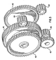
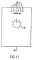
- Fig. 1 shows a wheelchair 10 according to the present invention.
- the wheelchair 10 comprises a frame 12, a seat 14, a seat back 16, two ground engaging drive wheels 18, two ground engaging front wheels 20, two hand rims 22, and a gearing system 23 (as shown in Fig. 2 ) that connects each hand rim 22 and motor 24 to each drive wheel 18.
- the drive wheels 18 are on either side of the frame 12 and are mounted to a wheel hub 26.
- the wheel hub 26 is rotatably mounted to the frame 12.
- the hand rims 22 are attached to hand rim shafts 28 via spokes 30.
- the gearing system is powered by two force inputs.
- One input is provided by a user.
- the other is provided by two electronically controlled motors, each powering one drive wheel.
- the motor 24 (as shown in Fig. 2 ) assists in that effort.
- the motor acts as more as the primary means for operating the wheelchair.
- the gearing system 23 comprises first and second gear assemblies, and a control system (shown in Fig. 7 ).
- the first and second gear assemblies are supported and protected by a gear cover 34, a gear housing 36, and a motor housing 38.
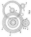
- the first gear assembly is a step-down gear reduction arrangement 39 that is associated with the force input supplied by the user.
- This first gear assembly includes a hand rim subassembly and a change gear subassembly.
- the hand rim subassembly comprises the hand rim 22 ( Fig. 1 ), a hand rim shaft 28, and a hand rim gear 40.
- the change gear subassembly ( Fig. 2 ) comprises a change gear 42, a change gear shaft 44, and a change gear pinion 46.
- a transducer 47 is located on the change gear shaft 44.
- reaction torque 55 ( Fig. 4 ) that is taken up by the gear supports.
- the transducer 47 measures this reaction torque, which gives an accurate measure to the control system of the force inputted by the user.
- the change gear assembly connects with an output gear assembly to act upon the drive wheel 18.
- the output gear assembly comprises an output gear 48 supported on an output shaft 50.
- the output shaft 50 passes through the gear cover 34 and connects with the wheel hub 26 to rotate the drive wheel 18 ( Fig.1 ).
- the hand rim assembly, the change gear assembly, and the output gear assembly cooperate in the following manner to transmit and enhance the user's force input to the drive wheels 18.
- the hand rim shaft 28 rotates as the user exerts a force upon each hand rim 22. This force is then transmitted directly to the hand rim gear 40 via the hand rim shaft 28, as shown in Figures 2 , 3 , 5 and 6 .
- the hand rim shaft 28 passes through the wheel hub 26, the output shaft 50, the gear cover 34, the output gear 48, the gear housing 36, and the hand rim gear 40 without significant diminution to the force being applied by the user. This may be accomplished by any suitable means, including but not limited to the use of bearings or a viscous substance such as lubricating oils. Either or all of the aforementioned elements may be used to provide support for the hand rim shaft 28 as it passes therethrough.
- the hand rim shaft 28 and the output shaft 50 are coaxial, but coupled through a N: 1 reduction ratio where N turns of the hand rim 22 produces one turn of the outer drive wheel 18.
- the present invention will work effectively with any value of N not equal to 1, although it will be most effective where N is between 0.5 to 2.0.
- a ratio larger than one is most preferred because this produces a multiplication of user handwheel torque, which allows the user to climb steep hills or ramps beyond the capability of the motor alone.
- the hand rim gear 40 rotates, it causes the change gear 42 to also rotate.
- the change gear 42 is attached to a change gear pinion 46 via a change gear shaft 44.
- the change gear shaft 44 passes through and may be supported by the gear housing 36 ( Fig. 2 ).
- the change gear pinion 46 meshes with the output gear 48, which causes the drive wheel 18 to rotate via the output shaft 50, which is connected to the wheel hub 26.
- the hand rim torque and the drive wheel torque will be different. This difference results in a reaction torque 55 ( Fig. 4 ) that is taken up by the gear supports.
- the transducer 47 (shown in Fig. 2 ), which is preferably a torque sensor based on strain-gauge technology, is mounted on the change gear shaft 44 ( Fig. 2 ) to measure this reaction torque.
- T h T r / N - 1
- T h is the torque applied by the user to the hand rim
- T r is the measured change gear reaction torque
- N is the change gear reduction ratio.
- the transducer 47 measures the hand rim torque T h and transmits this value to a central processing unit (CPU) 56.
- CPU central processing unit
- the second gear assembly is associated with the force input supplied by the motor and includes the motor 24, a rotor 58, a motor pinion 60, an intermediate gear 62, an intermediate gear pinion 66, and an intermediate shaft 68.
- the motor 24 provides electronically controlled power assistance that augments the force applied by the user.
- the force provided by the motor 24 is transmitted through a two-stage gear reduction 41, preferably having spur gears.
- the motor 24 is a brushless DC servomotor.
- the gear reduction ratio is approximately 18:1.
- the motor 24 is encased between the motor housing 38 and the gear housing 36. The combination of a high-performance, low-friction motor and a small reduction ration allows for minimal drivetrain drag when the motor 24 is unpowered, as could happen when the batteries run low or a system failure occurs.
- the motor 24 drives the motor pinion 60 through a shaft (not shown) passing through the gear housing 36.
- the motor pinion 60 meshes with the intermediate gear 62 through their associated gear teeth.
- the intermediate gear 62 connects to the intermediate gear pinion 66 via the intermediate shaft 68.
- the intermediate pinion 66 in-turn meshes with the output gear 48 to transmit the motor output to the drive wheel 18 (as shown in Fig. 1 ) through the output shaft 50, which is connected to the wheel hub 26.
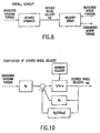
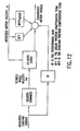
- Fig. 7 shows components of a control system and the data passing between these components.
- the control system comprises an external personal computer-based component 70, a battery 72, a velocity sensor 74, the transducer 47, a LED circuit 76, a control map 78 and associated circuitry, a user interface 80, the CPU 56, and the motor 24 having an associated motor driver 82.
- the control map 78 may be either constant to the system or selectable by the user through the interface 80 with the CPU 56.
- the control system operates through the CPU 56, which is preferably implemented as a programmable microprocessor.
- the circuitry for the control system is housed in a control box (not shown) that is, preferably, either integral with the drive unit/gear box or encased in a separate enclosure mounted on the frame.
- the control system operates so that the user supplies a force to the hand rim 22 that is measured by the transducer 47.
- the transducer 47 transmits this value to the CPU 56, which utilizes a desired dynamic or control map to transform the measured torque value into a desired drive wheel velocity.
- the desired dynamic may be programmed into the CPU and may be specifically configured to meet the needs of the individual user.
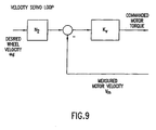
- a velocity servo loop ( Fig.
- the sensor 74 measures the actual drive wheel 18 velocity and compares that value against the optimum or desired value through the velocity servo loop. The motor output is then increased or decreased to reduce the error component to the optimum value of zero.
- the CPU 56 accepts torque input from the transducer 47, command input from the interface 80 (when used) and velocity input from the sensor 74. In response, the CPU 56 outputs a control signal to the motor 24 via the motor driver 82.
- the CPU 56 is preferably programmable through the use of the PC-based computer 70 having associated memory storage. Resident on the computer is a design tool for specifying and downloading these control maps to the CPU 56.
- the infra-red (IR) link 82 facilitates data transfer between the CPU 56 and the external computer 70.
- the CPU 56 also directs information downloaded from the data link, such as control maps, to an electrically erasable programmable read only memory (EEPROM). And, if the data link is appropriately configured to output information, the processor can upload data from a DRAM, or other volatile memory, via the data link. Software for governing the operation of the CPU 56 may also reside here. Furthermore, the CPU 56 may, upon request by the PC-based system 70, upload information that it has stored. Downloading and uploading are preferably performed by an infrared data link, although cabling, wireless data links, modems and other data exchange means may also be used.
- the various control maps may be accessed by the user through the use of the interface 80 ( Figs. 7 and 11 ) between the user and the CPU.
- the interface 80 is provided with a switch 90 that allows the user to select between the various control maps pre-programmed into the CPU.
- the interface 80 may also have a display comprising a series ofLEDs 78 used to indicate which control map has been selected by the user. Alternate displays (not shown), such as liquid crystal devices, displaying this information, along with other status data may be used in place of, or in addition to, the LEDs.
- the (IR) port 82 (shown in Fig. 7 ) facilitates communication with the PC-based component 70 to upload such data, and also to download control maps and other software. As stated above, other data links may be used in place of the IR port.
- N 1 is the gear ratio between the hand rim 22 to the outer drive wheel 18
- m is the desired mass of the system
- B 1 is the desired linear damping
- B 2 is the desired coulomb damping
- ⁇ d represents integration (1/s, Fig. 10 ). Due to the above formulas, the present invention is structured and tuned to mimic a wheelchair-like system with specific inertia and prescribed drag (combination of linear and coulomb friction).
- a feed forward signal path from the measured hand rim torque ( Fig. 12 ).
- the feed forward path applies a fixed ratio of torque to the motor, where the ratio is determined by the gain, K F .
- K F is the feed forward gain
- B F1 is the linear friction compensation term
- B F2 is the coulomb friction compensation term. Both the linear and coulomb friction compensation terms are used to eliminate natural friction in the system.
- These components (B F1 & B F2 ) add torque based upon speed, either linearly for B F1 or based on the sign of speed for B F2 .
- the present invention may utilize the feed forward term in both servo mode and by itself in feed forward mode. In servo mode, it helps the control system respond more quickly to operator input. Alone, it provides torque augmentation.
- variables in the above formulas can be altered over a wide range to tailor the control map to the specific needs of the user. For example, by specifying low inertia, the system will accelerate and decelerate more strongly in response to a torque input at the hand rims. The net effect is that the operator's inputs are amplified by the reciprocal of the system mass. This is referred as the "sensitivity" of the system.
- the preferred embodiment includes two types of damping, linear and coulomb. These damping terms are used both to tailor the response of the system to the needs of the user and to provide system stability. For example, the damping terms help the operator bring the speed to zero when desired and also keep the commanded speed at zero despite small offsets in the torque sensors.
- the linear damping term provides a resistive torque proportional to the desired speed that is similar to moving through a viscous fluid.
- the coulomb damping term provides a resistive torque of fixed magnitude that is similar to sliding an object across a smooth surface.
- damping may also be incorporated into the system, such as quadratic drag where the force increases with the square of the magnitude of the velocity. Increasing any damping term causes the desired velocity to return to zero more quickly in the absence of an applied torque input. At steady velocity, the drag terms set the amount of applied torque required to maintain that speed. If the damping terms are decreased, the chair will maintain its speed longer without additional torque input. The velocity limit simply prevents the desired velocity from exceeding a preset magnitude. From the user point of view, this feels much like heavy damping that cuts the limiting speed.
- An additional feature of the present invention is its regenerative capabilities. For example, when the motor is slowing down the wheelchair (as it does when in servo mode going downhill) power is routed back into the battery. Similarly, the chair brakes actively on level ground when the terms B 1 and B 2 ( Fig.10 ) reduce the desired velocity, and the velocity controller reduces the actual speed by applying the appropriate opposing torque. Then the regenerative action transfers energy from the kinetic energy of the moving mass back into the battery. Whenever the applied torque and velocity have opposite signs, the system puts much of the resulting dissipated power back into the battery, with the motor controller routing the generated electrical energy back into the battery. This capability is unique to the low-friction environment of the present system. This environment allows the wheelchair to coast when no current is applied.
- the desired dynamic is created by varying these parameters in association with the combination of the computer control system, the sensors, and the entire electromagnetic system (motors, gearing, etc). Due to the linearity of the torque motor, the low friction and low backlash of the gears, and the quality of the sensors, the computer control system can shape the overall dynamic system response over a wide range. Although the present invention will operate with high-friction, high-reduction gearing, this is not desirable because these components may constrain the ability to specify a desired system behavior.
- the control circuitry computes the desired motor output through the use of a single-axis velocity servo loop.
- the velocity servo loop alters the motor torque to maintain the desired wheel velocity ⁇ d despite changes in friction (external and internal) or gravity loads imposed by sloped terrains.
- K v is the velocity servo gain
- N 2 is the gearratio between the motor 24 and the outer drive wheel 18, and
- V m is the measured motor velocity.
- the measured motor velocity V m is obtained through the use of the sensor 74 associated with the motor 24.
- the sensor is an optical encoder mounted on the corresponding motor 24.
- the controller uses the desired motor output to transmit an appropriate control signal to the motor 24.
- This signal contains magnitude and polarity information which are presented to the motor driver 82 to produce an appropriate motor output.
- the motor driver 82 converts this signal into a voltage of the appropriate magnitude and polarity to be applied to the motor 24.
- the motor driver comprises a digital-to-analog converter (DAC), and an H-bridge circuit.
- the DAC converts the control signal into an analog signal to be applied to the H-bridge circuit, and the H-bridge circuit uses this signal, along with polarity information, to drive the motor 24.
- the gearing and control systems are duplicated for each wheel. Due to the independence of each wheel, the control system parameters can be varied to accommodate the user's particular needs. For example, if the user has less strength in one arm, the associated side of the wheelchair can be made more sensitive by reducing the mass and drag parameters. Alternatively, both systems can be coupled to produce a uniform response.
Claims (7)
- Véhicule assisté (10) comprenant :une roue motrice (18) ;des moyens d'entrée (22) destinés à recevoir un couple d'entraînement appliqué par un utilisateur ;un moteur (24) ;un ensemble de transmission (23) couplant le moteur à la roue motrice pour permettre au moteur d'entraîner la roue motrice et couplant les moyens d'entrée à la roue motrice de sorte à permettre aux moyens d'entrée d'entraîner simultanément la roue motrice ; etun système de commande programmé avec au moins une carte de commande définissant un comportement dynamique souhaité du véhicule et programmé avec un paramètre de masse souhaité et un paramètre de traînée souhaité,caractérisé en ce que le système de commande est configuré pour utiliser en alternance ladite carte de commande et les valeurs mesurées dudit couple d'entraînement appliqué par ledit utilisateur et une vitesse réelle pour déterminer une vitesse souhaitée et emploie une boucle d'asservissement de vitesse à simple axe pour commander le moteur en vue de réduire une composante erronée entre ladite vitesse réelle et ladite vitesse souhaitée ; oupour appliquer un rapport de couple fixé déterminé par un gain (KF) au moteur, ledit rapport étant appliqué par un chemin de signal à correction avant depuis le couple d'entraînement mesuré appliqué par ledit utilisateur.
- Véhicule (10) selon la revendication 1, dans lequel ladite vitesse souhaitée est produite en réponse à une intégration itérative :du couple mesuré appliqué par l'utilisateur multiplié par une première constante ; etde la valeur négative du signe de la vitesse souhaitée multipliée par une seconde constante.
- Véhicule (10) selon la revendication 1, dans lequel ladite vitesse souhaitée est produite en réponse à une intégration itérative :du couple mesuré appliqué par l'utilisateur multiplié par une première constante ; etd'un effet d'amortissement fourni par une fonction de la vitesse souhaitée.
- Véhicule (10) selon l'une quelconque des revendications précédentes formé comme un fauteuil roulant (10) comprenant :des premières et secondes roues d'entraînement (18), chacune présentant un axe et une main-courante coaxiale (22) pour la réception d'un couple d'entraînement appliqué par un utilisateur.
- Véhicule (10) selon la revendication 4, dans lequel ledit paramètre de traînée comprend un paramètre d'amortissement de Coulomb.
- Véhicule (10) selon la revendication 5, dans lequel ledit paramètre de traînée comprend en outre un paramètre d'amortissement linéaire.
- Véhicule (10) selon la revendication 5, dans lequel ladite vitesse souhaitée est produite en réponse à une intégration itérative :du couple de main-courante mesuré multiplié par une première constante ;de la valeur négative de la vitesse souhaitée multipliée par une seconde constante ; etde la valeur négative du signe de la vitesse souhaitée multipliée par une troisième constante.
Applications Claiming Priority (2)
| Application Number | Priority Date | Filing Date | Title |
|---|---|---|---|
| US38812499A | 1999-08-31 | 1999-08-31 | |
| EP00957922A EP1216184B1 (fr) | 1999-08-31 | 2000-08-30 | Vehicule a entrainement assiste |
Related Parent Applications (1)
| Application Number | Title | Priority Date | Filing Date |
|---|---|---|---|
| EP00957922.8 Division | 2000-08-30 |
Publications (3)
| Publication Number | Publication Date |
|---|---|
| EP2206640A2 EP2206640A2 (fr) | 2010-07-14 |
| EP2206640A3 EP2206640A3 (fr) | 2010-10-20 |
| EP2206640B1 true EP2206640B1 (fr) | 2012-06-06 |
Family
ID=23532806
Family Applications (2)
| Application Number | Title | Priority Date | Filing Date |
|---|---|---|---|
| EP00957922A Expired - Lifetime EP1216184B1 (fr) | 1999-08-31 | 2000-08-30 | Vehicule a entrainement assiste |
| EP10161759A Expired - Lifetime EP2206640B1 (fr) | 1999-08-31 | 2000-08-30 | Véhicule assisté |
Family Applications Before (1)
| Application Number | Title | Priority Date | Filing Date |
|---|---|---|---|
| EP00957922A Expired - Lifetime EP1216184B1 (fr) | 1999-08-31 | 2000-08-30 | Vehicule a entrainement assiste |
Country Status (7)
| Country | Link |
|---|---|
| US (2) | US6459962B2 (fr) |
| EP (2) | EP1216184B1 (fr) |
| JP (1) | JP2003517808A (fr) |
| DK (2) | DK1216184T3 (fr) |
| ES (1) | ES2424045T3 (fr) |
| HK (1) | HK1047721B (fr) |
| WO (1) | WO2001015960A1 (fr) |
Families Citing this family (58)
| Publication number | Priority date | Publication date | Assignee | Title |
|---|---|---|---|---|
| DK1216184T3 (da) | 1999-08-31 | 2013-03-25 | Deltaglide Inc | Køretøj med drivkraft-assistance |
| EP1181918A1 (fr) * | 2000-02-28 | 2002-02-27 | Yamaha Hatsudoki Kabushiki Kaisha | Chaise roulante medicale electrique |
| US6494278B1 (en) * | 2000-10-02 | 2002-12-17 | Ervin Weisz | Electric wheelchair drive system |
| US6946650B2 (en) * | 2002-03-04 | 2005-09-20 | Independence Technology, L.L.C. | Sensor |
| DE60319847T2 (de) * | 2002-08-29 | 2009-09-10 | Department Of Veterans Affairs, Rehabilitation R&D Service | Joystick mit variabler nachgiebigkeit mit kompensationsalgorithmen |
| US6819981B2 (en) * | 2003-04-21 | 2004-11-16 | Invacare Corporation | Method and apparatus for setting speed/response performance parameters of a power driven wheelchair |
| US6871122B1 (en) * | 2003-09-22 | 2005-03-22 | Invacare Corporation | Method of adjusting globally performance parameters of a power driven wheelchair |
| US7159181B2 (en) * | 2003-10-01 | 2007-01-02 | Sunrise Medical Hhg Inc. | Control system with customizable menu structure for personal mobility vehicle |
| US7865275B2 (en) * | 2003-10-10 | 2011-01-04 | Dynamic Controls Limited | Method and apparatus for controlling an electric vehicle function |
| US7113854B2 (en) * | 2003-10-22 | 2006-09-26 | Sunrise Medical Hhg Inc. | Personal mobility vehicle control system with input functions programmably mapped to output functions |
| WO2005094480A2 (fr) * | 2004-03-23 | 2005-10-13 | Motiv Technology, Inc | Dispositif d'assistance |
| US7222921B2 (en) * | 2004-07-15 | 2007-05-29 | Ethicon, Inc. | Wheelchair with foot rest |
| US7332881B2 (en) | 2004-10-28 | 2008-02-19 | Textron Inc. | AC drive system for electrically operated vehicle |
| US20060213699A1 (en) * | 2005-03-25 | 2006-09-28 | Mei-Ying Lin | Method for driving wheel-chair |
| US20070080656A1 (en) * | 2005-10-11 | 2007-04-12 | Sunrise Medical Hhg Inc. | Wheelchair with motor speed and torque control |
| US7931101B2 (en) * | 2006-10-13 | 2011-04-26 | Invacare Corporation | Proportional joystick with integral switch |
| KR100768644B1 (ko) * | 2006-12-15 | 2007-10-18 | 김덕영 | 보행보조기의 자동 브레이크장치 |
| US7926889B2 (en) | 2007-10-29 | 2011-04-19 | Textron Innovations Inc. | Hill hold for an electric vehicle |
| CN102105341B (zh) * | 2009-01-28 | 2013-01-02 | 日本精工株式会社 | 电动动力转向装置 |
| US20100200311A1 (en) * | 2009-02-11 | 2010-08-12 | Southern Taiwan University | Manually operatable motorized wheel chair |
| KR101100712B1 (ko) * | 2009-09-22 | 2011-12-30 | 김성윤 | 전자식 가속억제 및 충전 회로를 구비하는 보행보조기 |
| WO2011060345A2 (fr) | 2009-11-15 | 2011-05-19 | Invacare Corporation | Fauteuil roulant |
| NZ602419A (en) | 2010-03-16 | 2014-10-31 | Invacare Corp | Wheelchair seat assembly |
| US8931583B2 (en) | 2010-06-24 | 2015-01-13 | Invacare Corporation | Wheelchair |
| US20120067662A1 (en) * | 2010-09-22 | 2012-03-22 | Ulrich Alber Gmbh | Drive assistance device, wheelchair and method for determination of the manual driving force of a wheelchair driver |
| DE202010017965U1 (de) * | 2010-09-22 | 2013-05-02 | Ulrich Alber Gmbh | Hilfsantriebsvorrichtung, Rollstuhl und Vorrichtung zur Ermittlung von physischen Leistungsdaten eines Rollstuhlfahrers |
| US8496080B2 (en) | 2010-09-30 | 2013-07-30 | National Taiwan University | Wheel driven mechanism |
| USD667349S1 (en) | 2010-11-10 | 2012-09-18 | Invacare Corp. | Outer hub for a wheel |
| USD667761S1 (en) | 2010-11-10 | 2012-09-25 | Invacare Corp. | Tire |
| USD735622S1 (en) | 2011-04-04 | 2015-08-04 | Invacare Corp. | Armrest for a wheelchair |
| EP2729108B1 (fr) | 2011-07-06 | 2017-03-29 | William Mark Richter | Système d'aide motorisé basé sur le mouvement pour fauteuils roulants |
| USD722286S1 (en) | 2012-07-31 | 2015-02-10 | Invacare International Sarl | Wheelchair frame |
| USD735021S1 (en) | 2012-07-31 | 2015-07-28 | Invacare International Sarl | Caster wheel |
| CA149384S (en) | 2012-07-31 | 2014-04-16 | Invacare Internat S Rl | Wheelchair |
| US10004651B2 (en) | 2012-09-18 | 2018-06-26 | Stryker Corporation | Patient support apparatus |
| US9259369B2 (en) | 2012-09-18 | 2016-02-16 | Stryker Corporation | Powered patient support apparatus |
| US9144525B2 (en) | 2013-03-14 | 2015-09-29 | Max Mobility, Llc. | Motion assistance system for wheelchairs |
| WO2014152550A2 (fr) * | 2013-03-15 | 2014-09-25 | Stryker Corporation | Appareil de support médical |
| WO2015017456A2 (fr) * | 2013-07-31 | 2015-02-05 | Motiv Technology, Inc. | Système et procédé permettant de commander une bicyclette électrique à pédales |
| CA158705S (en) | 2014-03-13 | 2015-04-22 | Invacare Internat Sàrl | Wheelchair frame element |
| FR3020757A1 (fr) | 2014-05-12 | 2015-11-13 | Centre Nat Rech Scient | Procede et dispositif d'aide a la propulsion electrique d'un systeme roulant, kit pour fauteuil roulant comportant un tel dispositif et fauteuil roulant equipe d'un tel dispositif. |
| USD765839S1 (en) | 2014-05-15 | 2016-09-06 | Invacare International Sarl | Wheelchair table |
| US9644730B2 (en) | 2014-08-04 | 2017-05-09 | Global Research Innovation And Technology Inc. | Demountable coupling system and apparatus |
| US9795524B2 (en) | 2015-02-24 | 2017-10-24 | Max Mobility, Llc | Assistive driving system for a wheelchair |
| US10568792B2 (en) | 2015-10-28 | 2020-02-25 | Stryker Corporation | Systems and methods for facilitating movement of a patient transport apparatus |
| US20170198784A1 (en) * | 2016-01-12 | 2017-07-13 | Hanon Systems | Method and apparatus for transmitting torque in an actuator |
| US10603234B2 (en) | 2016-03-30 | 2020-03-31 | Stryker Corporation | Patient support apparatuses with drive systems |
| CN105997381B (zh) * | 2016-05-04 | 2017-09-05 | 许金华 | 一种轮椅 |
| IT201700041556A1 (it) * | 2017-04-13 | 2018-10-13 | Effortless Mobility S R L | Dispositivo di movimentazione motorizzato spinto a mano |
| EP3646836B1 (fr) * | 2017-06-26 | 2021-10-06 | Yamaha Hatsudoki Kabushiki Kaisha | Fauteuil roulant à assistance motorisée, unité d'assistance motorisée pour fauteuil roulant, dispositif de commande pour fauteuil roulant à assistance motorisée, procédé de commande pour fauteuil roulant à assistance motorisée, et programme |
| US10167051B1 (en) | 2017-12-12 | 2019-01-01 | Max Mobility, Llc | Assistive driving system for a wheelchair and method for controlling assistive driving system |
| AU2019322492B2 (en) * | 2018-04-27 | 2021-03-04 | Roda Futura, Llc | Removable power assist for manual wheelchair |
| US11154443B2 (en) | 2018-04-27 | 2021-10-26 | Roda Futura, Llc | Removable power assist for manual wheelchair |
| US11523951B2 (en) | 2018-04-27 | 2022-12-13 | Roda Futura, Llc | Portable power assist for manual wheelchairs |
| US10945899B2 (en) * | 2018-04-27 | 2021-03-16 | Roda Fuutra, Llc | Removable power assist for manual wheelchair |
| US11660241B2 (en) | 2018-04-27 | 2023-05-30 | Roda Futura, Llc | Exchangeable universal wheelchair power assist |
| US11529274B2 (en) | 2018-04-27 | 2022-12-20 | Roda Futura, Llc | Removable power assist for manual wheelchair |
| FR3101771B1 (fr) * | 2019-10-14 | 2024-04-12 | Electricite De France | Procédé de contrôle d’un dispositif d’assistance électrique |
Family Cites Families (71)
| Publication number | Priority date | Publication date | Assignee | Title |
|---|---|---|---|---|
| GB1587184A (en) | 1976-06-17 | 1981-04-01 | Harris J D Fodgen M F | Wheelchairs |
| US4050533A (en) | 1976-06-22 | 1977-09-27 | Government Of The United States Of America Rep. Administration Of Veterens Affairs | Powered wheel chair |
| US4116157A (en) * | 1976-11-15 | 1978-09-26 | Acf Industries, Incorporated | Rotatable visual indicator for safety systems |
| US4339013A (en) | 1980-05-12 | 1982-07-13 | Weigt Gerald I | Mobile and adaptable wheel chair |
| US4634941A (en) * | 1981-04-15 | 1987-01-06 | Invacare Corporation | Electric wheelchair with improved control circuit |
| US4422515A (en) | 1981-07-29 | 1983-12-27 | The United States of America as represented by the Admin. of Veterans Affairs | Motorized wheel chair |
| US4415049A (en) | 1981-09-14 | 1983-11-15 | Instrument Components Co., Inc. | Electrically powered vehicle control |
| US4627860A (en) | 1982-07-09 | 1986-12-09 | Hudson Oxygen Therapy Sales Company | Oxygen concentrator and test apparatus |
| US4667136A (en) | 1986-04-04 | 1987-05-19 | Gordon W. Rosenberg | Cross-coupling drive circuit |
| US4947036A (en) * | 1986-10-03 | 1990-08-07 | Conax Buffalo Corporation | Self-monitoring optical sensor having a ratiometric output signal |
| US4767940A (en) | 1987-10-02 | 1988-08-30 | Peachtree Patient Center, Inc. | Electronic sensing and control circuit |
| DE3807129A1 (de) * | 1988-03-04 | 1989-09-14 | Ortopedia Gmbh | Regelvorrichtung, insbesondere fuer rollstuhl |
| GB8806042D0 (en) | 1988-03-14 | 1988-04-13 | Lean G D | Proportional control system for engine assisted bicycle |
| US5033000A (en) | 1988-06-09 | 1991-07-16 | Natco Corporation | Variable keyed power distribution and control system for motorized wheelchair |
| IL91588A (en) | 1989-09-10 | 1994-10-07 | Propel Partnership 1987 | Electric drive attachment for wheelchairs |
| US5248007A (en) | 1989-11-21 | 1993-09-28 | Quest Technologies, Inc. | Electronic control system for stair climbing vehicle |
| US5234066A (en) * | 1990-11-13 | 1993-08-10 | Staodyn, Inc. | Power-assisted wheelchair |
| US5222567A (en) | 1991-04-26 | 1993-06-29 | Genus Inc. | Power assist device for a wheelchair |
| IL98207A (en) | 1991-05-22 | 1994-08-26 | Israel Aircraft Ind Ltd | Wheelchair with apparatus for assisting travel on a surface not suitable for wheeled travel |
| DE69233024T2 (de) | 1991-06-04 | 2003-10-16 | Yamaha Motor Co Ltd | Muskelgetriebenes Fahrzeug |
| US5356172A (en) | 1991-07-23 | 1994-10-18 | Zvi Gilad Smolinsky | Sliding seat assembly for a propelled wheel chair |
| IL98931A0 (en) | 1991-07-23 | 1992-07-15 | Tzora Furniture Ind Ltd | Wheelchairs |
| US5172039A (en) | 1991-09-16 | 1992-12-15 | Staodyn, Inc. | Device utilizing capacitive coupling to provide an output indicative of angular relationship |
| US5253724A (en) * | 1991-10-25 | 1993-10-19 | Prior Ronald E | Power wheelchair with transmission using multiple motors per drive wheel |
| US5274311A (en) | 1991-11-13 | 1993-12-28 | Quest Technologies, Inc. | Control system network structure |
| US5555949A (en) | 1992-02-18 | 1996-09-17 | Cerebral Palsy Research Foundation Of Kansas | Electricaly operable wheelchair having a controller responsive to different types of inputs |
| JP2634121B2 (ja) | 1992-03-06 | 1997-07-23 | ヤマハ発動機株式会社 | 電動モータ付き自転車およびそのモータ制御方法 |
| US5245558A (en) | 1992-03-11 | 1993-09-14 | Synergy | Computer system for disabled user |
| EP0561268B1 (fr) | 1992-03-19 | 1998-01-14 | Sanyo Electric Co., Ltd. | Bicyclette entraínée par un moteur et des pédales |
| US5270624A (en) | 1992-05-28 | 1993-12-14 | Lautzenhiser John L | Apparatus and method for enhancing torque of power wheelchair |
| JP2623419B2 (ja) | 1992-09-30 | 1997-06-25 | ヤマハ発動機株式会社 | 電動モータ付き自転車 |
| US5366037A (en) * | 1992-11-23 | 1994-11-22 | Invacare Corporation | Powered wheelchair having drive motors integrated into driven wheels |
| US5427193A (en) | 1993-04-19 | 1995-06-27 | Datatran Inc. | Drive system for wheelchairs or the like |
| SE9400869L (sv) * | 1993-08-16 | 1995-02-17 | Johan Carlsson | Rullstol med kraftservo samt mätfunktion |
| JP3430579B2 (ja) | 1993-10-05 | 2003-07-28 | 株式会社デンソー | 車両用通信システムの異常検出装置 |
| DE69418968T2 (de) | 1993-10-29 | 1999-09-30 | Yamaha Motor Co Ltd | Pedalfahrzeug mit elektrischem Hilfsmotor |
| US5664636A (en) | 1993-10-29 | 1997-09-09 | Yamaha Hatsudoki Kabushiki Kaisha | Vehicle with electric motor |
| TW467091U (en) * | 1994-03-29 | 2001-12-01 | Sanyo Electric Co | Electric bicycle |
| US5497056A (en) | 1994-05-10 | 1996-03-05 | Trenton State College | Method and system for controlling a motorized wheelchair using controlled braking and incremental discrete speeds |
| JP3661882B2 (ja) | 1994-06-16 | 2005-06-22 | ヤマハ発動機株式会社 | 補助動力式ビークル |
| EP0691232B1 (fr) * | 1994-07-06 | 2000-03-22 | Nabco Limited | Véhicule à moteur |
| US5448479A (en) | 1994-09-01 | 1995-09-05 | Caterpillar Inc. | Remote control system and method for an autonomous vehicle |
| US5788007A (en) | 1994-09-29 | 1998-08-04 | Miekka; Fred N. | Electromagnet vehicle drive |
| US5619412A (en) | 1994-10-19 | 1997-04-08 | Cummins Engine Company, Inc. | Remote control of engine idling time |
| US5737711A (en) | 1994-11-09 | 1998-04-07 | Fuji Jukogyo Kabuishiki Kaisha | Diagnosis system for motor vehicle |
| US5648708A (en) | 1995-05-19 | 1997-07-15 | Power Concepts, Inc. | Force actuated machine controller |
| JP3703524B2 (ja) | 1995-06-20 | 2005-10-05 | ヤマハ発動機株式会社 | 手動式電動車椅子 |
| JP3524640B2 (ja) | 1995-07-31 | 2004-05-10 | 三洋電機株式会社 | 車いす |
| US5732788A (en) * | 1995-09-14 | 1998-03-31 | Electric Mobility Corporation | Golf vehicle |
| JP3691132B2 (ja) | 1995-10-31 | 2005-08-31 | 三洋電機株式会社 | アシスト式乗り物 |
| JP3703554B2 (ja) * | 1996-02-14 | 2005-10-05 | ヤマハ発動機株式会社 | 補助動力付き車椅子 |
| US5798702A (en) | 1996-04-18 | 1998-08-25 | Suzuki Motor Corporation | Residual battery capacity display device for electric vehicle |
| JP3819478B2 (ja) * | 1996-06-27 | 2006-09-06 | 三洋電機株式会社 | 車いす |
| US5704876A (en) | 1996-06-28 | 1998-01-06 | Racer-Mate, Inc. | Wheelchair aerobic exercise trainer |
| JP3705378B2 (ja) | 1996-07-01 | 2005-10-12 | ヤマハ発動機株式会社 | 電動車椅子 |
| US6003627A (en) | 1996-08-08 | 1999-12-21 | Nabco Limited | Motor-driven vehicle control apparatus |
| JP3306309B2 (ja) | 1996-08-28 | 2002-07-24 | 三洋電機株式会社 | アシスト式電動車 |
| JPH1094106A (ja) | 1996-09-17 | 1998-04-10 | Yamaha Motor Co Ltd | 電動車両の駆動装置 |
| JPH1099379A (ja) | 1996-09-27 | 1998-04-21 | Yamaha Motor Co Ltd | 補助動力付き車椅子 |
| US6112837A (en) * | 1996-09-30 | 2000-09-05 | Yamaha Hatsudoki Kabushiki Kaisha | Manually operated, motor assisted wheelchair |
| US5988661A (en) | 1997-02-27 | 1999-11-23 | Garfinkle; Moishe | Drive assistance device for ordinary wheelchairs |
| DE19708058A1 (de) | 1997-02-28 | 1998-09-03 | Bock Orthopaed Ind | Muskelbetriebenes Radfahrzeug |
| JPH10314232A (ja) | 1997-05-19 | 1998-12-02 | Yamaha Motor Co Ltd | 補助動力式車椅子 |
| JP3954693B2 (ja) * | 1997-07-14 | 2007-08-08 | 本田技研工業株式会社 | 電動補助車両における入力トルク検出装置 |
| US6115367A (en) * | 1997-08-05 | 2000-09-05 | Vlsi Technology, Inc. | Methods of analyzing a radio signal and methods of analyzing a personal handy-phone system radio signal |
| US5922035A (en) | 1997-12-03 | 1999-07-13 | Winston Hsu | Fuzzy logic control system for electrical aided vehicle |
| DE69837702T2 (de) | 1997-12-26 | 2007-09-06 | Yamaha Hatsudoki K.K., Iwata | Lastsensor |
| DE19861127C2 (de) | 1998-03-21 | 2001-02-22 | Alber Ulrich Gmbh & Co Kg | Hilfsantriebsvorrichtung für Selbstfahrer-Rollstühle |
| US6202773B1 (en) | 1999-07-30 | 2001-03-20 | Invacare Corporation | Motorized wheelchairs |
| DK1216184T3 (da) * | 1999-08-31 | 2013-03-25 | Deltaglide Inc | Køretøj med drivkraft-assistance |
| EP1181918A1 (fr) | 2000-02-28 | 2002-02-27 | Yamaha Hatsudoki Kabushiki Kaisha | Chaise roulante medicale electrique |
-
2000
- 2000-08-30 DK DK00957922.8T patent/DK1216184T3/da active
- 2000-08-30 EP EP00957922A patent/EP1216184B1/fr not_active Expired - Lifetime
- 2000-08-30 DK DK10161759.5T patent/DK2206640T3/da active
- 2000-08-30 JP JP2001519541A patent/JP2003517808A/ja active Pending
- 2000-08-30 ES ES00957922T patent/ES2424045T3/es not_active Expired - Lifetime
- 2000-08-30 WO PCT/US2000/023815 patent/WO2001015960A1/fr active Application Filing
- 2000-08-30 EP EP10161759A patent/EP2206640B1/fr not_active Expired - Lifetime
-
2001
- 2001-06-21 US US09/886,874 patent/US6459962B2/en not_active Expired - Lifetime
-
2002
- 2002-09-24 US US10/253,281 patent/US6807465B2/en not_active Expired - Fee Related
- 2002-12-24 HK HK02109317.5A patent/HK1047721B/zh not_active IP Right Cessation
Also Published As
| Publication number | Publication date |
|---|---|
| DK1216184T3 (da) | 2013-03-25 |
| EP1216184B1 (fr) | 2013-01-02 |
| US6807465B2 (en) | 2004-10-19 |
| DK2206640T3 (da) | 2012-09-24 |
| JP2003517808A (ja) | 2003-05-27 |
| EP1216184A1 (fr) | 2002-06-26 |
| US6459962B2 (en) | 2002-10-01 |
| WO2001015960A1 (fr) | 2001-03-08 |
| EP1216184A4 (fr) | 2009-07-22 |
| US20030018417A1 (en) | 2003-01-23 |
| HK1047721A1 (en) | 2003-03-07 |
| EP2206640A3 (fr) | 2010-10-20 |
| HK1047721B (zh) | 2013-10-11 |
| EP2206640A2 (fr) | 2010-07-14 |
| ES2424045T3 (es) | 2013-09-26 |
| US20020019686A1 (en) | 2002-02-14 |
Similar Documents
| Publication | Publication Date | Title |
|---|---|---|
| EP2206640B1 (fr) | Véhicule assisté | |
| US6302226B1 (en) | Power assisted vehicle | |
| US5818189A (en) | Electric power-assisted wheelchair | |
| Ding et al. | Electric powered wheelchairs | |
| US4422515A (en) | Motorized wheel chair | |
| US4574903A (en) | Motor driven power steering system | |
| EP0787642A2 (fr) | Procédé et appareil pour la compensation d'effet du couple entraînant sur la direction | |
| WO2017129275A1 (fr) | Système d'entraînement de pédale, procédé de fonctionnement d'un système d'entraînement de pédale, et système d'entraînement électrique | |
| US9707138B2 (en) | Gear-shifting system for manually propelled wheelchairs | |
| EP2163467A1 (fr) | Véhicule | |
| EP0756856A2 (fr) | Fauteuil roulant | |
| US4685528A (en) | Electric power steering device for a motor vehicle | |
| US8641070B2 (en) | Drive assistance device, wheelchair and method for determination of the physical efficiency and muscular effort data of a wheelchair driver | |
| EP0265211B1 (fr) | Dispositif de commande pour direction assistée électriquement et chariot élévateur | |
| GB2136370A (en) | Steering systems for vehicles | |
| EP0309293A2 (fr) | Méthode de commande de l'angle de direction des roues avant | |
| EP1298051A2 (fr) | Unité avec moteur électrique | |
| EP0707842A1 (fr) | Véhicule à moteur | |
| US5996342A (en) | Hydrostatic drive train controller | |
| JP3608833B2 (ja) | 電動パワーステアリング装置 | |
| EP1234746B1 (fr) | Ensemble de direction assistée électrique pour véhicule automobile et procédé de commande associé | |
| WO2005094480A2 (fr) | Dispositif d'assistance | |
| JP2814149B2 (ja) | 駆動力補助装置付き自転車 | |
| JP4291732B2 (ja) | 輸送車両と方法 | |
| US20240017757A1 (en) | Motorized wagon and operation method thereof |
Legal Events
| Date | Code | Title | Description |
|---|---|---|---|
| PUAI | Public reference made under article 153(3) epc to a published international application that has entered the european phase |
Free format text: ORIGINAL CODE: 0009012 |
|
| AC | Divisional application: reference to earlier application |
Ref document number: 1216184 Country of ref document: EP Kind code of ref document: P |
|
| AK | Designated contracting states |
Kind code of ref document: A2 Designated state(s): AT BE CH CY DE DK ES FI FR GB GR IE IT LI LU MC NL PT SE |
|
| RIN1 | Information on inventor provided before grant (corrected) |
Inventor name: YOERGER, DANA R. Inventor name: ULRICH, NATHAN |
|
| PUAL | Search report despatched |
Free format text: ORIGINAL CODE: 0009013 |
|
| AK | Designated contracting states |
Kind code of ref document: A3 Designated state(s): AT BE CH CY DE DK ES FI FR GB GR IE IT LI LU MC NL PT SE |
|
| 17P | Request for examination filed |
Effective date: 20110419 |
|
| GRAP | Despatch of communication of intention to grant a patent |
Free format text: ORIGINAL CODE: EPIDOSNIGR1 |
|
| GRAS | Grant fee paid |
Free format text: ORIGINAL CODE: EPIDOSNIGR3 |
|
| GRAA | (expected) grant |
Free format text: ORIGINAL CODE: 0009210 |
|
| AC | Divisional application: reference to earlier application |
Ref document number: 1216184 Country of ref document: EP Kind code of ref document: P |
|
| AK | Designated contracting states |
Kind code of ref document: B1 Designated state(s): AT BE CH CY DE DK ES FI FR GB GR IE IT LI LU MC NL PT SE |
|
| REG | Reference to a national code |
Ref country code: GB Ref legal event code: FG4D |
|
| REG | Reference to a national code |
Ref country code: AT Ref legal event code: REF Ref document number: 560874 Country of ref document: AT Kind code of ref document: T Effective date: 20120615 Ref country code: CH Ref legal event code: EP |
|
| REG | Reference to a national code |
Ref country code: IE Ref legal event code: FG4D |
|
| REG | Reference to a national code |
Ref country code: DE Ref legal event code: R096 Ref document number: 60047261 Country of ref document: DE Effective date: 20120802 |
|
| REG | Reference to a national code |
Ref country code: NL Ref legal event code: T3 |
|
| REG | Reference to a national code |
Ref country code: DK Ref legal event code: T3 |
|
| REG | Reference to a national code |
Ref country code: SE Ref legal event code: TRGR |
|
| PG25 | Lapsed in a contracting state [announced via postgrant information from national office to epo] |
Ref country code: CY Free format text: LAPSE BECAUSE OF FAILURE TO SUBMIT A TRANSLATION OF THE DESCRIPTION OR TO PAY THE FEE WITHIN THE PRESCRIBED TIME-LIMIT Effective date: 20120606 Ref country code: FI Free format text: LAPSE BECAUSE OF FAILURE TO SUBMIT A TRANSLATION OF THE DESCRIPTION OR TO PAY THE FEE WITHIN THE PRESCRIBED TIME-LIMIT Effective date: 20120606 |
|
| RAP2 | Party data changed (patent owner data changed or rights of a patent transferred) |
Owner name: INDEPENDENCE TECHNOLOGY, L.L.C. |
|
| REG | Reference to a national code |
Ref country code: NL Ref legal event code: SD Effective date: 20121107 |
|
| REG | Reference to a national code |
Ref country code: AT Ref legal event code: MK05 Ref document number: 560874 Country of ref document: AT Kind code of ref document: T Effective date: 20120606 |
|
| PG25 | Lapsed in a contracting state [announced via postgrant information from national office to epo] |
Ref country code: GR Free format text: LAPSE BECAUSE OF FAILURE TO SUBMIT A TRANSLATION OF THE DESCRIPTION OR TO PAY THE FEE WITHIN THE PRESCRIBED TIME-LIMIT Effective date: 20120907 |
|
| REG | Reference to a national code |
Ref country code: GB Ref legal event code: 732E Free format text: REGISTERED BETWEEN 20121129 AND 20121205 |
|
| REG | Reference to a national code |
Ref country code: DE Ref legal event code: R081 Ref document number: 60047261 Country of ref document: DE Owner name: INDEPENDENCE TECHNOLOGY, L.L.C., US Free format text: FORMER OWNER: DELTAGLIDE, INC., HAMDEN, US Effective date: 20121031 Ref country code: DE Ref legal event code: R082 Ref document number: 60047261 Country of ref document: DE Representative=s name: KSNH PATENTANWAELTE KLUNKER & KOLLEGEN, DE Effective date: 20121031 Ref country code: DE Ref legal event code: R081 Ref document number: 60047261 Country of ref document: DE Owner name: INDEPENDENCE TECHNOLOGY, L.L.C., WARREN, US Free format text: FORMER OWNER: DELTAGLIDE, INC., HAMDEN, CONN., US Effective date: 20121031 Ref country code: DE Ref legal event code: R082 Ref document number: 60047261 Country of ref document: DE Representative=s name: KSNH PATENTANWAELTE KLUNKER/SCHMITT-NILSON/HIR, DE Effective date: 20121031 |
|
| PG25 | Lapsed in a contracting state [announced via postgrant information from national office to epo] |
Ref country code: AT Free format text: LAPSE BECAUSE OF FAILURE TO SUBMIT A TRANSLATION OF THE DESCRIPTION OR TO PAY THE FEE WITHIN THE PRESCRIBED TIME-LIMIT Effective date: 20120606 Ref country code: BE Free format text: LAPSE BECAUSE OF FAILURE TO SUBMIT A TRANSLATION OF THE DESCRIPTION OR TO PAY THE FEE WITHIN THE PRESCRIBED TIME-LIMIT Effective date: 20120606 |
|
| PG25 | Lapsed in a contracting state [announced via postgrant information from national office to epo] |
Ref country code: PT Free format text: LAPSE BECAUSE OF FAILURE TO SUBMIT A TRANSLATION OF THE DESCRIPTION OR TO PAY THE FEE WITHIN THE PRESCRIBED TIME-LIMIT Effective date: 20121008 |
|
| REG | Reference to a national code |
Ref country code: CH Ref legal event code: PL |
|
| PG25 | Lapsed in a contracting state [announced via postgrant information from national office to epo] |
Ref country code: MC Free format text: LAPSE BECAUSE OF NON-PAYMENT OF DUE FEES Effective date: 20120831 |
|
| PLBE | No opposition filed within time limit |
Free format text: ORIGINAL CODE: 0009261 |
|
| STAA | Information on the status of an ep patent application or granted ep patent |
Free format text: STATUS: NO OPPOSITION FILED WITHIN TIME LIMIT |
|
| PG25 | Lapsed in a contracting state [announced via postgrant information from national office to epo] |
Ref country code: LI Free format text: LAPSE BECAUSE OF NON-PAYMENT OF DUE FEES Effective date: 20120831 Ref country code: ES Free format text: LAPSE BECAUSE OF FAILURE TO SUBMIT A TRANSLATION OF THE DESCRIPTION OR TO PAY THE FEE WITHIN THE PRESCRIBED TIME-LIMIT Effective date: 20120917 Ref country code: CH Free format text: LAPSE BECAUSE OF NON-PAYMENT OF DUE FEES Effective date: 20120831 |
|
| 26N | No opposition filed |
Effective date: 20130307 |
|
| REG | Reference to a national code |
Ref country code: IE Ref legal event code: MM4A |
|
| REG | Reference to a national code |
Ref country code: DE Ref legal event code: R097 Ref document number: 60047261 Country of ref document: DE Effective date: 20130307 |
|
| PG25 | Lapsed in a contracting state [announced via postgrant information from national office to epo] |
Ref country code: IE Free format text: LAPSE BECAUSE OF NON-PAYMENT OF DUE FEES Effective date: 20120830 |
|
| PG25 | Lapsed in a contracting state [announced via postgrant information from national office to epo] |
Ref country code: LU Free format text: LAPSE BECAUSE OF NON-PAYMENT OF DUE FEES Effective date: 20120830 |
|
| REG | Reference to a national code |
Ref country code: FR Ref legal event code: PLFP Year of fee payment: 16 |
|
| PGFP | Annual fee paid to national office [announced via postgrant information from national office to epo] |
Ref country code: NL Payment date: 20150809 Year of fee payment: 16 |
|
| PGFP | Annual fee paid to national office [announced via postgrant information from national office to epo] |
Ref country code: GB Payment date: 20150826 Year of fee payment: 16 Ref country code: DK Payment date: 20150811 Year of fee payment: 16 Ref country code: DE Payment date: 20150825 Year of fee payment: 16 |
|
| PGFP | Annual fee paid to national office [announced via postgrant information from national office to epo] |
Ref country code: SE Payment date: 20150811 Year of fee payment: 16 Ref country code: FR Payment date: 20150629 Year of fee payment: 16 |
|
| PGFP | Annual fee paid to national office [announced via postgrant information from national office to epo] |
Ref country code: IT Payment date: 20150827 Year of fee payment: 16 |
|
| REG | Reference to a national code |
Ref country code: DE Ref legal event code: R119 Ref document number: 60047261 Country of ref document: DE |
|
| REG | Reference to a national code |
Ref country code: DK Ref legal event code: EBP Effective date: 20160831 |
|
| REG | Reference to a national code |
Ref country code: SE Ref legal event code: EUG |
|
| REG | Reference to a national code |
Ref country code: NL Ref legal event code: MM Effective date: 20160901 |
|
| GBPC | Gb: european patent ceased through non-payment of renewal fee |
Effective date: 20160830 |
|
| PG25 | Lapsed in a contracting state [announced via postgrant information from national office to epo] |
Ref country code: SE Free format text: LAPSE BECAUSE OF NON-PAYMENT OF DUE FEES Effective date: 20160831 |
|
| REG | Reference to a national code |
Ref country code: FR Ref legal event code: ST Effective date: 20170428 |
|
| PG25 | Lapsed in a contracting state [announced via postgrant information from national office to epo] |
Ref country code: NL Free format text: LAPSE BECAUSE OF NON-PAYMENT OF DUE FEES Effective date: 20160901 |
|
| PG25 | Lapsed in a contracting state [announced via postgrant information from national office to epo] |
Ref country code: GB Free format text: LAPSE BECAUSE OF NON-PAYMENT OF DUE FEES Effective date: 20160830 Ref country code: FR Free format text: LAPSE BECAUSE OF NON-PAYMENT OF DUE FEES Effective date: 20160831 Ref country code: DK Free format text: LAPSE BECAUSE OF NON-PAYMENT OF DUE FEES Effective date: 20160831 Ref country code: DE Free format text: LAPSE BECAUSE OF NON-PAYMENT OF DUE FEES Effective date: 20170301 |
|
| PG25 | Lapsed in a contracting state [announced via postgrant information from national office to epo] |
Ref country code: IT Free format text: LAPSE BECAUSE OF NON-PAYMENT OF DUE FEES Effective date: 20160830 |