EP2205979B1 - Syringe system - Google Patents
Syringe system Download PDFInfo
- Publication number
- EP2205979B1 EP2205979B1 EP08799979.3A EP08799979A EP2205979B1 EP 2205979 B1 EP2205979 B1 EP 2205979B1 EP 08799979 A EP08799979 A EP 08799979A EP 2205979 B1 EP2205979 B1 EP 2205979B1
- Authority
- EP
- European Patent Office
- Prior art keywords
- syringe
- plunger
- barrel
- coupling mechanism
- mounting apparatus
- Prior art date
- Legal status (The legal status is an assumption and is not a legal conclusion. Google has not performed a legal analysis and makes no representation as to the accuracy of the status listed.)
- Active
Links
Images




Classifications
-
- G—PHYSICS
- G01—MEASURING; TESTING
- G01N—INVESTIGATING OR ANALYSING MATERIALS BY DETERMINING THEIR CHEMICAL OR PHYSICAL PROPERTIES
- G01N35/00—Automatic analysis not limited to methods or materials provided for in any single one of groups G01N1/00 - G01N33/00; Handling materials therefor
- G01N35/10—Devices for transferring samples or any liquids to, in, or from, the analysis apparatus, e.g. suction devices, injection devices
- G01N35/1009—Characterised by arrangements for controlling the aspiration or dispense of liquids
- G01N35/1011—Control of the position or alignment of the transfer device
-
- B—PERFORMING OPERATIONS; TRANSPORTING
- B01—PHYSICAL OR CHEMICAL PROCESSES OR APPARATUS IN GENERAL
- B01L—CHEMICAL OR PHYSICAL LABORATORY APPARATUS FOR GENERAL USE
- B01L3/00—Containers or dishes for laboratory use, e.g. laboratory glassware; Droppers
- B01L3/02—Burettes; Pipettes
- B01L3/021—Pipettes, i.e. with only one conduit for withdrawing and redistributing liquids
- B01L3/0217—Pipettes, i.e. with only one conduit for withdrawing and redistributing liquids of the plunger pump type
- B01L3/0234—Repeating pipettes, i.e. for dispensing multiple doses from a single charge
-
- G—PHYSICS
- G01—MEASURING; TESTING
- G01N—INVESTIGATING OR ANALYSING MATERIALS BY DETERMINING THEIR CHEMICAL OR PHYSICAL PROPERTIES
- G01N35/00—Automatic analysis not limited to methods or materials provided for in any single one of groups G01N1/00 - G01N33/00; Handling materials therefor
- G01N35/10—Devices for transferring samples or any liquids to, in, or from, the analysis apparatus, e.g. suction devices, injection devices
- G01N2035/1027—General features of the devices
- G01N2035/103—General features of the devices using disposable tips
-
- G—PHYSICS
- G01—MEASURING; TESTING
- G01N—INVESTIGATING OR ANALYSING MATERIALS BY DETERMINING THEIR CHEMICAL OR PHYSICAL PROPERTIES
- G01N35/00—Automatic analysis not limited to methods or materials provided for in any single one of groups G01N1/00 - G01N33/00; Handling materials therefor
- G01N35/10—Devices for transferring samples or any liquids to, in, or from, the analysis apparatus, e.g. suction devices, injection devices
- G01N2035/1027—General features of the devices
- G01N2035/1048—General features of the devices using the transfer device for another function
- G01N2035/1053—General features of the devices using the transfer device for another function for separating part of the liquid, e.g. filters, extraction phase
Definitions
- the present invention relates generally to syringe mounting apparatus optionally having application to analytical syringe systems such as auto-sampler systems.
- the invention is concerned with reducing and preferably eliminating the risk of cross contamination or sample carryover associated with sampling using an analytical syringe.
- auto-samplers have made a significant impact on the efficiency, speed and reproducibility of sample processing and injection into analytical instrumentation. Despite these benefits there remains a significant challenge on improving the reduction of sample carryover or cross contamination to a level of eliminating it altogether.
- the elimination of carry over in auto-samplers is essential for the analysis of clinical samples as well as samples that carry a broad dynamic range of analytes, such as blood plasma, where the range in concentration of analytes can be as large as 10 10 to 10 12 between the least and most abundant proteins.
- sample injection volumes are small, for e.g. ⁇ 2 ⁇ l, it is possible to limit the aspiration of a sample to the surfaces of the auto-sampler syringe needle and dispose of the needle between samples.
- disposable polypropylene tips meet this need, but they are not of sufficient rigidity to pierce the sample vial septa nor are they of the correct design to interface with the typical analytical instrument's injection port. Hence, a metal needle is considered necessary.
- Patent application WO2006/083695 A2 discloses a sampling probe known from the prior art that features a quick connect coupling for syringes.
- the present inventors have realised that it is possible to develop an improved syringe mounting apparatus and analysis system that are capable of addressing both of the above-mentioned deficiencies with present auto-sampler configurations.
- the invention provides a syringe mounting apparatus including: a body; a coupling mechanism on the body having a housing to receive a barrel of a syringe component, the barrel having a longitudinal axis, the housing mounted for being moved down onto and about the end of the barrel, and the coupling mechanism further having a mechanism configured to detachably engage the barrel and thereby interchangeably retain the syringe component as the housing is so moved; and a plunger connector having an axis, the plunger connector being receivable in a concentric cavity in the housing for operably detachably coupling a plunger driver to a plunger element carried in the barrel of a syringe component when the syringe component is interchangeably retained by the coupling mechanism, wherein in use the plunger connector is moved downwardly onto the end of the plunger element until it detachably engages the plunger element in a manner allowing the plunger driver to thereafter effect reciprocatory movement of the plunger element longitudinally of the barrel
- the invention provides a syringe system comprising a syringe mounting apparatus as discussed above, and a structure that includes a plunger driver and that supports the syringe mounting apparatus for movement laterally and vertically in a work space, the syringe system further including control means programmable or programmed for selectively effecting the movement, for operating the plunger driver, and to selectively engage and disengage successive syringe components.
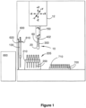
- the analytical syringe system depicted in Figure 1 includes a multi-axis auto-sampler 12, and an array 205 of syringe components including washable and reusable syringe components 100 retained upright in a stand 210 and disposable components 200 retained in stand 600.
- Syringe mounting apparatus 10 is provided on a translatable syringe pick-up head 300 depending from auto-sampler 12 and has a syringe coupling mechanism 20 and a plunger connector 60. The latter is carried by a w-axis plunger driver 402 at its lower end for vertical, i.e. longitudinal, reciprocal movement relative to coupling mechanism 20.
- Stand 600 also defines a fixed position 610 at which a disposable syringe component may be detached from pick-up head 300 for disposal. It will be appreciated that Figure 1 is not to scale.
- the syringe mounting apparatus 10 comprising coupling mechanism 20 and plunger connector 60 is configured to detachably and interchangeably directly engage and pick up one of multiple larger volume re-usable syringe components 100 ( Figure 4 ), or, by means of an adaptor 250, successive disposable smaller-volume syringe components 200 ( Figure 11 ).
- coupling mechanism 20 includes a generally cylindrical hollow housing 22 with an upper peripheral external groove 24 that received the two halves 25a, 25a of a clamp device 25 by which the housing is suspended from pick-up head 300.
- a counterbore 26 houses a ring of spaced balls 28 retained in holes 29 of a co-axial sleeve 30.
- Sleeve 30 is firmly secured by an interference fit in an annular rebate from the main bore 23 of housing 22.
- Holes 29 are sized and shaped so that the balls 28 protrude inwardly from them but cannot pass through, and the balls are biased to this position by a ring 32.
- Ring 32 is axially slidable about the outside of sleeve 30, seats balls 28 obliquely and is biased against the balls by a helical compression spring 34 retained between ring 32 and a peripheral flange 31 of sleeve 30 that abuts the rim of housing 22.
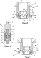
- Balls 28 are lockable into the illustrated protruding position by a slide member 36 that is transversely moveable between an inactive position ( Figure 5 ) and an active position ( Figure 7 ) in which a shoulder 37 on the slide underlies the lower rim of ring 32 at one side and prevents it from sliding downwardly against spring 34.
- the two positions of slide 36 are indexed by respective pairs of magnets 38a, 39a; 38b, 39b in the upper surface of the slide and in an opposing downwardly facing surface of housing 22.
- Plunger connector 60 ( Figures 2 , 3 and 6 ) includes a solid cylindrical main body 62 with a central upstanding post 63 by which the main body 62 is linked to w-axis plunger driver 402 of the auto analysesr pick-up head 300. At its other, lower, end, body 62 has an integral depending thin-walled annular partition 64 that is offset inwardly to define an outer seat for an outer, axially slidable, collar 66 and an inner seat for a helical compression spring 67.
- An inner, fixed, collar 68 threadably engages an inner threaded portion of partition 64 and has a peripheral external end flange 70 that defines a lower limit of travel for collar 66.
- Collar 66 is biased to this limit by spring 67 and has an inside annular groove 72 that receives respective balls 74 retained in holes 75 in collar 68 from which the balls 74 can protrude but not pass through.
- the assembly is completed by an inner plunger abutment member 76 slidably moveable within collar 68 between a lower limit at which a peripheral lip 78 at the upper rim of the abutment member abuts the upper rim of collar 68, and an upper limit adjacent an inner endface 79 of body 62.
- Abutment member 76 is biased to the lower limit by a helical compression spring 80 retained in blind bores 82, 83 in body 62 and abutment member 76.
- a typical interchangeable syringe component 100 is shown in Figure 4 . It has an elongate barrel 102, a projecting hollow needle 105, and a plunger 110 longitudinally slidable within the barrel for aspirating liquid sample into needle 105, and usually also barrel 102, and/or injecting liquid sample from the needle.
- Barrel 102 includes a precision made tubular glass body 112, an end insert seal 114 at one end of body 112 with a fine aperture 125 therethrough, an endpiece 116 in which the needle is mounted, and, at the other end of body 112, an end fitting 120 dimensioned for engagement with coupling mechanism 20.
- End fitting 120 has a tubular forward portion with an external end taper 121 and a peripheral groove 122 of arcuate cross-section to receive balls 28 of the coupling mechanism.
- a rearward skirt 124 is fitted about the end of glass body 112 and an intermediate portion 126 defines a second groove 128 of rectangular cross-section and an annular shoulder 129.
- the inner end of plunger 110 has an end cap 130 that sealingly slidably engages the inner surface of glass body 112 in the usual manner.
- the plunger's outer end has an end piece 132 dimensioned for receipt within inner collar 68 of plunger connector 60, and provided with a peripheral groove 134 of arcuate cross-section to receive balls 74 of the plunger connector.
- pick up head 300 When it is desired to pick up a re-usable syringe 100 for performing an aspiration/injection operation, pick up head 300 is moved into position over a selected syringe in array 600.
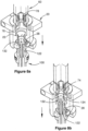
- the sequence of operations is depicted in Figures 8a, 8b and 2 or 3 .
- the plunger driver 402 positions plunger connector 60 at a position just projecting into an enlarged concentric cavity 21 in the upper part of housing 22 (refer figure 5 ).
- Housing 22 moves down onto and about the syringe component 100 ( Figure 8a ) until end taper 21 pushes balls 28 back through holes 29, from which they are subsequently pushed by spring 34 into grooves 122 ( Figure 8b ): at this point flange 31 strikes shoulder 129 to limit downward movement of the coupling housing 22.
- Driver 402 now brings the driver connector onto plunger end piece 132, which relatively pushes back plunger abutment member 76 (against spring 80) to expose balls 74 for engagement in groove 134: this motion allows spring 67 to push collar 66 down to prevent release of balls 74 and so lock the parts together.
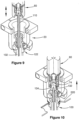
- the picked up syringe component 100 can now be translated to one or more selected vials and one or more instrument ports, e.g. an injection port of an analyser, moved vertically in the z-axis (e.g. to drive needle 105 to pierce a vial) and driver 402 operated to aspirate sample into the syringe component 100 ( Figure 9 ) or to inject sample therefrom (e.g. into an injection port of an analyser).
- Performed operations may of course include washing the re-usable syringe component at a washing station.
- the analyser may be one or more of a gas chromatograph, a liquid chromatograph, a mass spectrometer or any combination of two or more of these.
- disengagement is effected by returning the syringe component to a cutout 610 on a projecting plate 620 of stand 600, or another stand, at which the rim 220 of a recess engages groove 128 of the syringe barrel end fitting 120 ( Figure 10 ).
- slide member 36 is engaged and pushed to its inactive position ( Figure 5 ).
- a small downward push by driver 402 will relatively push back collar 66 and allow balls 74 to be pushed outwardly into groove 72 as the pick-up head is raised.
- pick-up head 300 may be employed to engage smaller volume disposable syringe elements 200.
- an adaptor 250 is necessary, firstly to allow engagement with coupling mechanism 20, and secondly to provide a further plunger connector element to couple the plunger driver to a plunger element in the barrel of the syringe component ( Figure 11 ).
- a typical disposable syringe element 200 is illustrated in Figure 12 . It comprises a barrel 202 about an interior cavity 209, a hollow needle 205 that projects from a closed end of barrel 202 so that fluid may be drawn into cavity 209 or expelled from the cavity through the needle, and a plunger tip 210. Tip 210 is sealingly slidable in cavity 209 for drawing fluid into needle 205 or expelling fluid therefrom.
- Barrel 202 includes a main tubular glass body 212 along cavity 209, an endpiece or front cap 216 that is press fit into one end of glass tube 212 and also receives needle 205, and a cap portion or back flange 203 of annular cross-section that press fits over the other end of glass body 212 and has an outer deformable lip 211.
- Plunger tip 210 is an integral solid body, typically of PTFE, UHMWPE or Ekonol ® -filled PTFE, with a rearward open socket 215 that is deformable to receive a spigot comprising a complementary head 261 ( Figure 11 ) at the end of plunger stem 260 of adaptor 250.
- the socket may have a peripheral rim that snaps about the head but deforms to allow disengagement under sufficient axial force.
- Adaptor 250 ( Figure 11 ) includes a central two-part elongate plunger stem 260 with an integral spigot 261 at its lower end for detachably engaging plunger tip 210 as aforedescribed.
- stem 260 has an end piece 232 similar in dimensions and form to end-piece 132 of syringe component 100: it too is detachably engageable with plunger connector 60 so that plunger connector 60 and plunger stem 260 in effect form an enlarged plunger connector for operably coupling driver 402 to plunger element 210 in barrel 202 of disposable syringe component 200.
- Adaptor 250 further has respective inner and outer relatively slidable sleeve members 255, 257 with an internal helical compressing spring 265 between then that biases sleeve members 255, 257 apart to a condition in which a head 256 on the inner sleeve member 255 abuts an enclosing back flange 258 on the outer sleeve member 257.
- an internal undercut peripheral groove 268 in outer sleeve member 257 adjacent its lower end is immediately below the lower end of inner sleeve member 255 and so can snap engage the deformable lip 211 of syringe barrel back flange 203.
- a tubular shaft extension 266 of inner sleeve member 255 has, at its outer end, an end-fitting 220 of identical external profile to end-fitting 120, for similarly engaging coupling mechanism 20 and stand 600.
- Syringe component 200 can be disengaged from adaptor 250 by abutting the lower end face of outer sleeve member 257 onto a stop extending about the syringe component, such as plate 620 of stand 600 ( Figure 1 ). Downward force by the pick-up head 300 will cause inner sleave member 255 to push against back flange 203 and disengage it from undercut groove 268: it will fall away, typically into an underlying receptacle for disposal.
- the adaptor 250 may have an alternative end configuration 220' such as shown in Figure 13 for being mounted on other auto-sampler systems.
- Figure 14 depicts an alternative adaptor 250' in which like parts relative to the adaptor of Figure 11 are indicated by like primed reference numerals.
- the syringe is pushed against syringe ejection mechanism 282 which compresses spring 284.
- syringe ejection mechanism 282 compresses spring 284.
- outer sleeve 257' is forced downwards over slotted clutch mechanism 281.
- Clutch fingers of mechanism 281 tightly hold the syringe barrel in place.
- Plunger stem 260' is forced downwards into plunger tip 210'.
- the syringe can now be used as previously described.
- the coupling mechanism needs to be moved to the disposal station 620.
- the plunger drive moves upwards moving the plunger tip 210' upwards to strike face 287 of ejection mechanism 282.
- the plunger stem 260' continues to be withdrawn and in doing so the plunger tip 210' is removed from the plunger stem 260'.
- the adaptor mechanism 250' is moved downwards until face 280 of outer sleeve 257' strikes the upper face of bracket 600.
- Adaptor mechanism 250' continues to be forced downwards against the force of the spring 283. This action removes the force against the clutch fingers of mechanism 281 and the syringe 200' is actively pushed away from coupling mechanism 250' by ejection mechanism 282 which has spring force acting upon it from compression spring 284.
- the ejection mechanism 282 passes shoulder 286 and blocks the clutch fingers of mechanism 281 from closing, thus allowing a new disposable syringe 200' to be inserted.
- Figure 15 depicts a second embodiment of the invention in which a coupler mechanism 500 directly engages with a disposable syringe component 900.
- syringe component 900 is similar in principle to disposable syringe component 200, but differs in detail.
- Like parts are indicated by like reference numerals commencing with a "9" in place of "2".
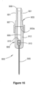
- Syringe component 900 ( Figure 16 ) comprises a barrel 902 about an interior cavity 909, a hollow needle 905 that projects from a closed end of barrel 902 so that fluid may be drawn into cavity 909 or expelled from the cavity through the needle, and a plunger tip 910.
- Tip 910 is sealingly slidable in cavity 909 for drawing fluid into needle 905 or expelling fluid therefrom.
- Barrel 902 includes a main tubular body 912 along cavity 903, and a cap portion 903 of annular cross-section that snap fits over the body 912 so as to define an internal annular shoulder 903a at the boundary between the two parts.
- the exterior of cap portion 903 has an annular shoulder 907 facing away from the needle, and a groove 901 near an externally chamfered distal end 908.
- Plunger tip 910 is an integral solid body, typically of PTFE, UHMWPE or Ekonol ® -filled PTFE, with a rearward open socket 915 that is deformable to receive a spigot comprising a complementary head 401 at the end of a plunger connector 460, in the form of a bi-truncated sphere.
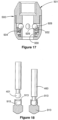
- the socket 915 has a peripheral rim 913 that snaps about the head ( Fig 18 , right view) but deforms to allow disengagement under sufficient axial force.
- array 205 in Figure 1 comprises disposable syringe components 900.
- Array 205 is positioned on the multi-axis auto-sampler 100 to facilitate aspiration of samples from vials 700 using a controller 800 of the sampler that is programmed to robotically execute a series of actions.
- the pick-up head 300 is moved by the controller 800 to the array of disposable elements 900 and lowered in the Z-axis so that the plunger connector 460 inserts into and engages plunger tip 910 within the disposable component 900.
- a two-part interlock sleeve 501 of system 500 ( Figure 17 ) has received cap portion 903 of the barrel 902 of disposable component 200, and multiple springloaded balls 928 in holes 929 on the sleeve 930 of the syringe barrel interlock engage the complementary groove 901 of the disposable component (see FIG. 15 ).
- Balls 928 are held in position by an axially moveable ring 932 that obliquely seats balls 928 and is itself engaged by a helical spring 934 to bias the balls inwardly. Balls 928 are pushed back by chamfer 908 and then drop into groove 901 to complete the connection of the two elements.
- the mounted syringe component is now moved by the controller 800 to the array of sample vials 700.
- the syringe component 900 is lowered in the Z-axis so that the needle 905 pierces the selected vial septum 710 and travels a sufficient distance to be below the meniscus of the sample contained within the vial.
- a separate W-axis control 150 of the auto-sampler operates driver 402 to retract the plunger connector 460 and thereby plunger tip 910 to draw sample into the connected disposable component 900 at a predetermined rate and volume. In this case, the volume of sample drawn only contacts the features of the disposable component - the hollow needle 905, the barrel 902 and the plunger tip 910.
- the sample is now dispensed into a number of preferred elements such as a separate sample vial, a mixing vial or an analytical instrument.
- the pick-up head 300 is moved over to waste station/stand 600. Removal of the disposable syringe component 200 follows two steps: The disposable component 200 is positioned under the fixed position 610 by placing strike surface 907 on barrel cap 903 against and below the tongue 610 of stand 600. The controller moves the pick-up head in the positive Z-axis and, on engagement of strike surface 907 with tongue 610 acting as a complementary stop, forces the features 200 and 500 to decouple.
- the disposable component is still connected to the plunger connector 460 at the plunger tip 910.
- Continued travel of the pick-up head 300 in the positive Z-axis now retracts the plunger tip 910 into engagement with a stop defined by annular shoulder 903a. Any further travel of the plunger driver 402 will result in the decoupling, resulting in the disposable component falling freely into a waste bin below waste system 600.
- the plunger tip 910 remains within the element 200 on disposal.
- the process can now be repeated using a new disposable syringe component 200 for each sample 700.
- any of the illustrated syringes may be adapted for solid phase microextraction (SPME) analysis by incorporating a solid phase material within barrel 102, 202, 902 (e.g. as a porous plug, coating or filter) or within a needle (e.g. as an insert, coated cylinder or interchangeable cartridge).
- the solid phase material may be, e.g., a silica-based material, a molecular imprinting polymer, polydimethylsiloxane or polystyrene-divinylbenzene.
Landscapes
- Physics & Mathematics (AREA)
- Health & Medical Sciences (AREA)
- Life Sciences & Earth Sciences (AREA)
- Chemical & Material Sciences (AREA)
- Analytical Chemistry (AREA)
- Biochemistry (AREA)
- General Health & Medical Sciences (AREA)
- General Physics & Mathematics (AREA)
- Immunology (AREA)
- Pathology (AREA)
- Sampling And Sample Adjustment (AREA)
Description
- The present invention relates generally to syringe mounting apparatus optionally having application to analytical syringe systems such as auto-sampler systems. In one aspect, the invention is concerned with reducing and preferably eliminating the risk of cross contamination or sample carryover associated with sampling using an analytical syringe.
- In the field of analytical science, auto-samplers have made a significant impact on the efficiency, speed and reproducibility of sample processing and injection into analytical instrumentation. Despite these benefits there remains a significant challenge on improving the reduction of sample carryover or cross contamination to a level of eliminating it altogether. The elimination of carry over in auto-samplers is essential for the analysis of clinical samples as well as samples that carry a broad dynamic range of analytes, such as blood plasma, where the range in concentration of analytes can be as large as 1010 to 1012 between the least and most abundant proteins.
- The problems associated with the risk of sample carry over can be so significant that only a truly disposable injection system will suffice. Where sample injection volumes are small, for e.g. < 2 µl, it is possible to limit the aspiration of a sample to the surfaces of the auto-sampler syringe needle and dispose of the needle between samples. To a great extent, disposable polypropylene tips meet this need, but they are not of sufficient rigidity to pierce the sample vial septa nor are they of the correct design to interface with the typical analytical instrument's injection port. Hence, a metal needle is considered necessary.
- For samples greater than the internal volume of the needle or disposable tip, the sample inevitably contacts the internal surfaces of the precision analytical syringe barrel and plunger tip. Once this occurs it is essential to wash the syringe rigorously to remove any risk of sample cross contamination. In the field of clinical assays the perceived risk is so high that disposal of each syringe is sometimes preferable, albeit at great expense with presently available analysis systems.
- Another issue with current auto-samplers is their relative lack of flexibility. They typically have fixed arrays of syringes arranged in gantry style on a robotic arm or as discrete moveable heads. In general, these auto-samplers are designed to carry out preprogrammed repetitive bulk analysis tasks at standard uniform sample volumes, and are not easily adaptable to rapid interchangeability between tasks. This issue is addressed in one way by the system disclosed in international patent publication
WO 2005/124366 , in which a multi-axis transport mechanism selectively moves syringe devices among multiple analysis stations at each of which the devices are detached. Each syringe device is a self-contained "smart" sample probe with an inbuilt motor and controller to effect aspiration and/or dispensing operations. This approach is sophisticated in concept and execution but unduly so for many requirements. - Patent application
WO2006/083695 A2 discloses a sampling probe known from the prior art that features a quick connect coupling for syringes. - The present inventors have realised that it is possible to develop an improved syringe mounting apparatus and analysis system that are capable of addressing both of the above-mentioned deficiencies with present auto-sampler configurations.
- In a first aspect, the invention provides a syringe mounting apparatus including: a body; a coupling mechanism on the body having a housing to receive a barrel of a syringe component, the barrel having a longitudinal axis, the housing mounted for being moved down onto and about the end of the barrel, and the coupling mechanism further having a mechanism configured to detachably engage the barrel and thereby interchangeably retain the syringe component as the housing is so moved; and a plunger connector having an axis, the plunger connector being receivable in a concentric cavity in the housing for operably detachably coupling a plunger driver to a plunger element carried in the barrel of a syringe component when the syringe component is interchangeably retained by the coupling mechanism, wherein in use the plunger connector is moved downwardly onto the end of the plunger element until it detachably engages the plunger element in a manner allowing the plunger driver to thereafter effect reciprocatory movement of the plunger element longitudinally of the barrel for drawing fluid into or expelling fluid from the syringe component, characterised in that the coupling mechanism comprises balls lockable into a protruding position by a slide member that is movable transversely to the longitudinal barrel axis between an inactive position and an active position in which a shoulder on the slide member underlies the lower rim of a ring at one side and prevents it from sliding against a spring, the active and the inactive positions of the slide member being indexed by respective pairs of magnets in the upper surface of the slide member and in an opposing surface of the housing.
- Preferred features of the syringe mounting apparatus are recited in claims 2 to 12 of the appended claims.
- In a second aspect, the invention provides a syringe system comprising a syringe mounting apparatus as discussed above, and a structure that includes a plunger driver and that supports the syringe mounting apparatus for movement laterally and vertically in a work space, the syringe system further including control means programmable or programmed for selectively effecting the movement, for operating the plunger driver, and to selectively engage and disengage successive syringe components.
- Preferred features of the syringe system are recited in claims 14 to 19 of the appended claims.
- Throughout the specification, unless the context requires otherwise, the word "comprise", or variations such as comprises or comprising, will be understood to imply the inclusion of a stated element, integer or step, or group of elements, integers or steps, but not the exclusion of any other element, integer or step, or group of elements, integers or steps.
- In order that the present invention may be more clearly understood, preferred forms will be described with reference to the following examples and accompanying drawings.
-
Figure 1 is a schematic not-to-scale representation in elevation of the layout of an analytical syringe system, incorporating syringe mounting apparatus according to the present invention; -
Figure 2 is an axial cross-section of a syringe mounting apparatus according to a first embodiment of the invention with an interchangeable syringe component fully engaged in the apparatus; -
Figure 3 is a cut-away partial isometric view of the apparatus depicted inFigure 2 ; -
Figures 4 ,5 and 6 are respective axial cross-sectional views of the syringe component, the coupling mechanism and the plunger connector as seen inFigures 2 and3 ; -
Figure 7 is a view similar toFigure 5 but showing the locking slide in its locking condition. -
Figures 8a and 8b are views similar toFigure 3 showing successive stages in the process of engaging the syringe mounting apparatus with an interchangeable syringe component; -
Figure 9 is a view similar toFigure 3 but with the plunger connector, and the plunger element of the interchangeable syringe component displaced upwardly; -
Figure 10 is a view similar toFigure 3 during disengagement of the syringe apparatus from the interchangeable syringe component; -
Figure 11 is an axial cross-section of an assembly of a small-volume disposable syringe component according to an embodiment of the second aspect of the invention and an adaptor by which the syringe mounting apparatus ofFigures 2 and3 may interchangeably engage the disposable syringe component; -
Figure 12 is an axial cross-section of the disposable syringe component depicted inFigure 11 ; -
Figure 13 is a fragmentary view of an alternative end-fitting for the adaptor depicted inFigure 12 ; -
Figure 14 is a similar view toFigure 11 , showing an alternative form of the adaptor; -
Figure 15 is an axial cross-section of syringe mounting apparatus according to a second embodiment of the invention, suitable for direct engagement with a disposable syringe component according to an embodiment of the second aspect of the invention. -
Figures 16 and17 are respective axial cross-sections of the disposable syringe component and the coupling mechanism depicted inFigure 15 ; and -
Figure 18 comprises schematic partly sectioned views of the syringe plunger connector about to engage, and engaged with, the plunger tip within the disposable syringe component in the embodiment ofFigures 15 to 17 . - The analytical syringe system depicted in
Figure 1 includes a multi-axis auto-sampler 12, and anarray 205 of syringe components including washable andreusable syringe components 100 retained upright in astand 210 anddisposable components 200 retained instand 600.Syringe mounting apparatus 10 is provided on a translatable syringe pick-up head 300 depending from auto-sampler 12 and has asyringe coupling mechanism 20 and aplunger connector 60. The latter is carried by a w-axis plunger driver 402 at its lower end for vertical, i.e. longitudinal, reciprocal movement relative tocoupling mechanism 20.Stand 600 also defines afixed position 610 at which a disposable syringe component may be detached from pick-up head 300 for disposal. It will be appreciated thatFigure 1 is not to scale. - In a first embodiment of the invention, the
syringe mounting apparatus 10 comprisingcoupling mechanism 20 andplunger connector 60 is configured to detachably and interchangeably directly engage and pick up one of multiple larger volume re-usable syringe components 100 (Figure 4 ), or, by means of anadaptor 250, successive disposable smaller-volume syringe components 200 (Figure 11 ). - As best seen in
Figures 3 and5 ,coupling mechanism 20 includes a generally cylindricalhollow housing 22 with an upper peripheralexternal groove 24 that received the twohalves clamp device 25 by which the housing is suspended from pick-uphead 300. - At the other, lower, end of
housing 22, acounterbore 26 houses a ring of spacedballs 28 retained inholes 29 of aco-axial sleeve 30.Sleeve 30 is firmly secured by an interference fit in an annular rebate from themain bore 23 ofhousing 22.Holes 29 are sized and shaped so that theballs 28 protrude inwardly from them but cannot pass through, and the balls are biased to this position by aring 32.Ring 32 is axially slidable about the outside ofsleeve 30,seats balls 28 obliquely and is biased against the balls by ahelical compression spring 34 retained betweenring 32 and aperipheral flange 31 ofsleeve 30 that abuts the rim ofhousing 22. -
Balls 28 are lockable into the illustrated protruding position by aslide member 36 that is transversely moveable between an inactive position (Figure 5 ) and an active position (Figure 7 ) in which ashoulder 37 on the slide underlies the lower rim ofring 32 at one side and prevents it from sliding downwardly againstspring 34. The two positions ofslide 36 are indexed by respective pairs ofmagnets housing 22. - Plunger connector 60 (
Figures 2 ,3 and6 ) includes a solid cylindricalmain body 62 with a centralupstanding post 63 by which themain body 62 is linked to w-axis plunger driver 402 of the autoanalyser pick-up head 300. At its other, lower, end,body 62 has an integral depending thin-walledannular partition 64 that is offset inwardly to define an outer seat for an outer, axially slidable,collar 66 and an inner seat for ahelical compression spring 67. - An inner, fixed,
collar 68 threadably engages an inner threaded portion ofpartition 64 and has a peripheralexternal end flange 70 that defines a lower limit of travel forcollar 66. Collar 66 is biased to this limit byspring 67 and has an insideannular groove 72 that receivesrespective balls 74 retained inholes 75 incollar 68 from which theballs 74 can protrude but not pass through. - The assembly is completed by an inner
plunger abutment member 76 slidably moveable withincollar 68 between a lower limit at which aperipheral lip 78 at the upper rim of the abutment member abuts the upper rim ofcollar 68, and an upper limit adjacent aninner endface 79 ofbody 62.Abutment member 76 is biased to the lower limit by ahelical compression spring 80 retained inblind bores body 62 andabutment member 76. - A typical
interchangeable syringe component 100 is shown inFigure 4 . It has anelongate barrel 102, a projectinghollow needle 105, and aplunger 110 longitudinally slidable within the barrel for aspirating liquid sample intoneedle 105, and usually alsobarrel 102, and/or injecting liquid sample from the needle.Barrel 102 includes a precision madetubular glass body 112, anend insert seal 114 at one end ofbody 112 with afine aperture 125 therethrough, anendpiece 116 in which the needle is mounted, and, at the other end ofbody 112, an end fitting 120 dimensioned for engagement withcoupling mechanism 20. - End fitting 120 has a tubular forward portion with an
external end taper 121 and aperipheral groove 122 of arcuate cross-section to receiveballs 28 of the coupling mechanism. Arearward skirt 124 is fitted about the end ofglass body 112 and anintermediate portion 126 defines asecond groove 128 of rectangular cross-section and anannular shoulder 129. - The inner end of
plunger 110 has anend cap 130 that sealingly slidably engages the inner surface ofglass body 112 in the usual manner. The plunger's outer end has anend piece 132 dimensioned for receipt withininner collar 68 ofplunger connector 60, and provided with aperipheral groove 134 of arcuate cross-section to receiveballs 74 of the plunger connector. - When it is desired to pick up a
re-usable syringe 100 for performing an aspiration/injection operation, pick uphead 300 is moved into position over a selected syringe inarray 600. The sequence of operations is depicted inFigures 8a, 8b and2 or3 . Theplunger driver 402positions plunger connector 60 at a position just projecting into an enlargedconcentric cavity 21 in the upper part of housing 22 (referfigure 5 ). -
Housing 22 moves down onto and about the syringe component 100 (Figure 8a ) untilend taper 21pushes balls 28 back throughholes 29, from which they are subsequently pushed byspring 34 into grooves 122 (Figure 8b ): at thispoint flange 31strikes shoulder 129 to limit downward movement of thecoupling housing 22.Driver 402 now brings the driver connector ontoplunger end piece 132, which relatively pushes back plunger abutment member 76 (against spring 80) to exposeballs 74 for engagement in groove 134: this motion allowsspring 67 to pushcollar 66 down to prevent release ofballs 74 and so lock the parts together. - As the
syringe component 100 is now drawn out ofstand 600 by pick-uphead 300, a magnet on the stand drawsslide member 36 to the locking position depicted inFigure 7 . The picked upsyringe component 100 can now be translated to one or more selected vials and one or more instrument ports, e.g. an injection port of an analyser, moved vertically in the z-axis (e.g. to driveneedle 105 to pierce a vial) anddriver 402 operated to aspirate sample into the syringe component 100 (Figure 9 ) or to inject sample therefrom (e.g. into an injection port of an analyser). Performed operations may of course include washing the re-usable syringe component at a washing station. The analyser may be one or more of a gas chromatograph, a liquid chromatograph, a mass spectrometer or any combination of two or more of these. - When operations are complete and it is desired to exchange the syringe component for another (e.g. a freshly washed syringe component or a syringe component of different volume) disengagement is effected by returning the syringe component to a
cutout 610 on a projectingplate 620 ofstand 600, or another stand, at which therim 220 of a recess engagesgroove 128 of the syringe barrel end fitting 120 (Figure 10 ). During this movement,slide member 36 is engaged and pushed to its inactive position (Figure 5 ). A small downward push bydriver 402 will relatively push backcollar 66 and allowballs 74 to be pushed outwardly intogroove 72 as the pick-up head is raised. This disengages the plunger from the plunger connector, while the retraction ofballs 28 fromgroove 122 simultaneously disengages the barrel end-fitting 120 from coupling mechanism 20 (Figure 10 ). Instead of picking up washable/re-usable syringe components 100, pick-uphead 300 may be employed to engage smaller volumedisposable syringe elements 200. - Because these
disposable syringe components 200 are typically of smaller volume and therefore smaller overall dimensions thansyringe components 100, anadaptor 250 is necessary, firstly to allow engagement withcoupling mechanism 20, and secondly to provide a further plunger connector element to couple the plunger driver to a plunger element in the barrel of the syringe component (Figure 11 ). - A typical
disposable syringe element 200 is illustrated inFigure 12 . It comprises abarrel 202 about aninterior cavity 209, ahollow needle 205 that projects from a closed end ofbarrel 202 so that fluid may be drawn intocavity 209 or expelled from the cavity through the needle, and aplunger tip 210.Tip 210 is sealingly slidable incavity 209 for drawing fluid intoneedle 205 or expelling fluid therefrom. -
Barrel 202 includes a maintubular glass body 212 alongcavity 209, an endpiece orfront cap 216 that is press fit into one end ofglass tube 212 and also receivesneedle 205, and a cap portion or backflange 203 of annular cross-section that press fits over the other end ofglass body 212 and has an outerdeformable lip 211. -
Plunger tip 210 is an integral solid body, typically of PTFE, UHMWPE or Ekonol®-filled PTFE, with a rearwardopen socket 215 that is deformable to receive a spigot comprising a complementary head 261 (Figure 11 ) at the end of plunger stem 260 ofadaptor 250. The socket may have a peripheral rim that snaps about the head but deforms to allow disengagement under sufficient axial force. - Adaptor 250 (
Figure 11 ) includes a central two-partelongate plunger stem 260 with anintegral spigot 261 at its lower end for detachably engagingplunger tip 210 as aforedescribed. At its other end, stem 260 has anend piece 232 similar in dimensions and form to end-piece 132 of syringe component 100: it too is detachably engageable withplunger connector 60 so thatplunger connector 60 and plunger stem 260 in effect form an enlarged plunger connector foroperably coupling driver 402 toplunger element 210 inbarrel 202 ofdisposable syringe component 200. -
Adaptor 250 further has respective inner and outer relativelyslidable sleeve members helical compressing spring 265 between then thatbiases sleeve members head 256 on theinner sleeve member 255 abuts an enclosing backflange 258 on theouter sleeve member 257. - In this condition, an internal undercut
peripheral groove 268 inouter sleeve member 257 adjacent its lower end is immediately below the lower end ofinner sleeve member 255 and so can snap engage thedeformable lip 211 of syringe barrel backflange 203. At the back or top end of the adaptor, atubular shaft extension 266 ofinner sleeve member 255 has, at its outer end, an end-fitting 220 of identical external profile to end-fitting 120, for similarly engagingcoupling mechanism 20 and stand 600. -
Syringe component 200 can be disengaged fromadaptor 250 by abutting the lower end face ofouter sleeve member 257 onto a stop extending about the syringe component, such asplate 620 of stand 600 (Figure 1 ). Downward force by the pick-uphead 300 will causeinner sleave member 255 to push againstback flange 203 and disengage it from undercut groove 268: it will fall away, typically into an underlying receptacle for disposal. - Instead of the specific configuration of end fitting 220 and end-
piece 232 for engaging the syringe apparatus ofFigures 2 and3 , theadaptor 250 may have an alternative end configuration 220' such as shown inFigure 13 for being mounted on other auto-sampler systems. -
Figure 14 depicts an alternative adaptor 250' in which like parts relative to the adaptor ofFigure 11 are indicated by like primed reference numerals. In order in attach disposable syringe 200' to adaptor 250', the syringe is pushed againstsyringe ejection mechanism 282 which compressesspring 284. Once ejection mechanism reachesshoulder 286, outer sleeve 257' is forced downwards over slottedclutch mechanism 281. Clutch fingers ofmechanism 281 tightly hold the syringe barrel in place. Plunger stem 260' is forced downwards into plunger tip 210'. The syringe can now be used as previously described. In order to decouple the syringe 200' the coupling mechanism needs to be moved to thedisposal station 620. At this position the plunger drive moves upwards moving the plunger tip 210' upwards to strikeface 287 ofejection mechanism 282. At this point the plunger stem 260' continues to be withdrawn and in doing so the plunger tip 210' is removed from the plunger stem 260'. Once the plunger tip 210' has been decoupled the adaptor mechanism 250' is moved downwards untilface 280 of outer sleeve 257' strikes the upper face ofbracket 600. Adaptor mechanism 250' continues to be forced downwards against the force of thespring 283. This action removes the force against the clutch fingers ofmechanism 281 and the syringe 200' is actively pushed away from coupling mechanism 250' byejection mechanism 282 which has spring force acting upon it fromcompression spring 284. Theejection mechanism 282 passesshoulder 286 and blocks the clutch fingers ofmechanism 281 from closing, thus allowing a new disposable syringe 200' to be inserted. -
Figure 15 depicts a second embodiment of the invention in which acoupler mechanism 500 directly engages with adisposable syringe component 900. In this embodiment,syringe component 900 is similar in principle todisposable syringe component 200, but differs in detail. Like parts are indicated by like reference numerals commencing with a "9" in place of "2". - Syringe component 900 (
Figure 16 ) comprises abarrel 902 about aninterior cavity 909, ahollow needle 905 that projects from a closed end ofbarrel 902 so that fluid may be drawn intocavity 909 or expelled from the cavity through the needle, and aplunger tip 910.Tip 910 is sealingly slidable incavity 909 for drawing fluid intoneedle 905 or expelling fluid therefrom. -
Barrel 902 includes a maintubular body 912 alongcavity 903, and acap portion 903 of annular cross-section that snap fits over thebody 912 so as to define an internalannular shoulder 903a at the boundary between the two parts. The exterior ofcap portion 903 has anannular shoulder 907 facing away from the needle, and agroove 901 near an externally chamfereddistal end 908. -
Plunger tip 910 is an integral solid body, typically of PTFE, UHMWPE or Ekonol®-filled PTFE, with a rearwardopen socket 915 that is deformable to receive a spigot comprising acomplementary head 401 at the end of aplunger connector 460, in the form of a bi-truncated sphere. Thesocket 915 has aperipheral rim 913 that snaps about the head (Fig 18 , right view) but deforms to allow disengagement under sufficient axial force. - For the purposes of this embodiment,
array 205 inFigure 1 comprisesdisposable syringe components 900.Array 205 is positioned on the multi-axis auto-sampler 100 to facilitate aspiration of samples fromvials 700 using acontroller 800 of the sampler that is programmed to robotically execute a series of actions. The pick-uphead 300 is moved by thecontroller 800 to the array ofdisposable elements 900 and lowered in the Z-axis so that theplunger connector 460 inserts into and engagesplunger tip 910 within thedisposable component 900. Simultaneously, as theplunger connector 460 inserts into theplunger 910, a two-part interlock sleeve 501 of system 500 (Figure 17 ) has receivedcap portion 903 of thebarrel 902 ofdisposable component 200, and multiplespringloaded balls 928 inholes 929 on thesleeve 930 of the syringe barrel interlock engage thecomplementary groove 901 of the disposable component (seeFIG. 15 ).Balls 928 are held in position by an axiallymoveable ring 932 that obliquely seatsballs 928 and is itself engaged by ahelical spring 934 to bias the balls inwardly.Balls 928 are pushed back bychamfer 908 and then drop intogroove 901 to complete the connection of the two elements. - The assembly is illustrated in
Figure 15 . It will be seen that the forward end ofinterlock sleeve 501 seats against ashoulder 907 ofbarrel cap portion 903, and that the distal end ofcap portion 903 is a firm sliding fit withinsleeve 930. - The mounted syringe component is now moved by the
controller 800 to the array ofsample vials 700. Thesyringe component 900 is lowered in the Z-axis so that theneedle 905 pierces the selectedvial septum 710 and travels a sufficient distance to be below the meniscus of the sample contained within the vial. A separate W-axis control 150 of the auto-sampler operatesdriver 402 to retract theplunger connector 460 and therebyplunger tip 910 to draw sample into the connecteddisposable component 900 at a predetermined rate and volume. In this case, the volume of sample drawn only contacts the features of the disposable component - thehollow needle 905, thebarrel 902 and theplunger tip 910. The sample is now dispensed into a number of preferred elements such as a separate sample vial, a mixing vial or an analytical instrument. - Once the sample has been dispensed the pick-up
head 300 is moved over to waste station/stand 600. Removal of thedisposable syringe component 200 follows two steps:
Thedisposable component 200 is positioned under the fixedposition 610 by placingstrike surface 907 onbarrel cap 903 against and below thetongue 610 ofstand 600. The controller moves the pick-up head in the positive Z-axis and, on engagement ofstrike surface 907 withtongue 610 acting as a complementary stop, forces thefeatures - Despite the decoupling of
features plunger connector 460 at theplunger tip 910. Continued travel of the pick-uphead 300 in the positive Z-axis now retracts theplunger tip 910 into engagement with a stop defined byannular shoulder 903a. Any further travel of theplunger driver 402 will result in the decoupling, resulting in the disposable component falling freely into a waste bin belowwaste system 600. Theplunger tip 910 remains within theelement 200 on disposal. - The process can now be repeated using a new
disposable syringe component 200 for eachsample 700. - In a modification (not illustrated), any of the illustrated syringes may be adapted for solid phase microextraction (SPME) analysis by incorporating a solid phase material within
barrel
Claims (19)
- Syringe mounting apparatus (10) including:a body (25);a coupling mechanism (20) on the body (25) having a housing (22) to receive a barrel (102) of a syringe component (100), the barrel (102) having a longitudinal axis, the housing (22) mounted for being moved axially onto and about the end of the barrel (102), and the coupling mechanism (20) further having a mechanism configured to detachably engage the barrel (102) and thereby interchangeably retain the syringe component (100) as the housing (22) is so moved; anda plunger connector (60) having an axis, the plunger connector (60) being receivable in a concentric cavity (21) in the housing (22) for operably detachably coupling a plunger driver (402) to a plunger element (110) carried in the barrel (102) of a syringe component (100) when the syringe component (100) is interchangeably retained by the coupling mechanism,wherein in use the plunger connector (60) is moved axially onto the end of the plunger element (110) until it detachably engages the plunger element (110) in a manner allowing the plunger driver (402) to thereafter effect reciprocatory movement of the plunger element (110) longitudinally of the barrel (102) for drawing fluid into or expelling fluid from the syringe component (100),characterised in that the coupling mechanism (20) comprises balls (28) lockable into a protruding position by a slide member (36) that is movable transversely to the longitudinal barrel axis between an inactive position and an active position in which a shoulder (37) on the slide member (36) underlies the lower rim of a ring (32) at one side and prevents it from sliding against a spring (34), the active and the inactive positions of the slide member (36) being indexed by respective pairs of magnets (38a, 39a; 38b, 39b) in the upper surface of the slide member (36) and in an opposing surface of the housing (22).
- Syringe mounting apparatus (10) according to claim 1 wherein the balls (28) are engageable with co-operating formations on the barrel (102) of the syringe component (100).
- Syringe mounting apparatus (10) according to claim 2 wherein the plunger connector comprises transversely retractable elements or formations (74) engageable with co-operating formations on the plunger element (110).
- Syringe mounting apparatus (10) according to any one of claims 1 to 3 wherein the housing (22) of the coupling mechanism (20) includes a sleeve (30) and the balls (28) are retained by the sleeve (30) engageable with co-operating formations on the barrel (102) of the syringe component (100).
- Syringe mounting apparatus (10) according to claim 4 further including a device to lock the balls (28) against retraction, whereby to lock the barrel (102) engaged thereby in the coupling mechanism (20).
- Syringe mounting apparatus (10) according to any one of claims 1 to 5 for use with syringe components (100) having the plunger element (110) in the form of a plunger tip (210), wherein the plunger connector (60) further includes an elongate plunger arranged to reciprocate longitudinally through the coupling mechanism (20) and within the barrel (102) of the syringe component (100), which plunger has a head portion that is detachably engageable with the plunger tip (210) within the barrel (102).
- Syringe mounting apparatus (10) according to any one of claims 1 to 6, for use with a syringe component (100) having the plunger element (110) that projects from the barrel (102), wherein the plunger connector (60) comprises a housing (22) to receive the plunger element (110) and means to detachably engage the plunger element (110).
- Syringe mounting apparatus (10) according to claim 7 wherein the means to detachably engage the plunger element (110) comprises a sleeve assembly and second resiliently retractable elements or formations (74) within the sleeve assembly engageable with co-operating formations on the plunger element (110).
- Syringe mounting apparatus (10) according to claim 7 or 8 wherein the coupling mechanism (20) includes an adaptor (250) having a first portion interchangeably receivable by and detachably engageable with the coupling mechanism (20), and a second portion detachably engageable with the barrel (102) of the syringe component (100) too small to be interchangeably retained by the coupling mechanism (20), the adaptor (250) having a longitudinally extending cavity therethrough for the plunger element (110) and/or plunger connector (60).
- Syringe mounting apparatus (10) according to claim 9 for use with syringe components (100) having the plunger element (110) in the form of a plunger tip (210), wherein the plunger connector (60) further includes an elongate plunger mounted in the adaptor cavity and arranged to reciprocate longitudinally through the coupling mechanism (20) and within the barrel (102) of the syringe component (100), which plunger tip (210) has a tip portion that is detachably engageable with the plunger tip (210) within the barrel (102).
- Syringe mounting apparatus (10) according to claim 9 or 10 wherein the adaptor (250) comprises respective inner and outer relatively slidable sleeve members (255, 257) arranged whereby movement of one of the sleeve members (255, 257) when the other is against a stop is effective to disengage the barrel (102) of the retained syringe component (100) from a formation in the other sleeve member.
- Syringe mounting apparatus (10) according to claim 9, 10 or 11 wherein the first portion of the adaptor (250) is interchangeable for other syringe mounting formations.
- A syringe system comprising the syringe mounting apparatus (10) of any one of claims 1 to 12, and a structure that includes a plunger driver (402) and that supports the syringe mounting apparatus (10) for movement laterally and vertically in a work space, the syringe system further including control means programmable or programmed for selectively effecting the movement, for operating the plunger driver (402), and to selectively engage and disengage successive syringe components (100).
- A syringe system according to claim 13 in combination with an analyser.
- A syringe system according to claim 13 or 14 including a plurality of re-usable syringe components (100) detachably engageable by and thereby interchangeably retainable by the coupling mechanism (20).
- A syringe system according to claim 13 or 14 including a plurality of disposable syringe components (100) detachably engageable by and thereby interchangeably retainable by the coupling mechanism (20) wherein the disposable syringe components (100) each comprise:a syringe barrel (102);a hollow needle (105) projecting from an end of the barrel (102);a syringe plunger tip (210) sealingly slidable in the barrel (102) for drawing fluid into the needle or expelling fluid through the needle (105); andmeans on the plunger tip (210) detachably engageable with a plunger for driving the plunger tip (210) to slide in the barrel (102).
- A syringe system according to claim 13 or claim 14 including a plurality of disposable syringe components (100) and one or more adaptors (250) each having a first portion interchangeably receivable by and detachably engageable with the coupling mechanism (20), and a second portion detachably engageable with a barrel (102) of a disposable syringe component (100), the adaptor (250) having a longitudinally extending cavity therethrough for the plunger element (110) and/or plunger connector (60).
- A syringe system according to claim 17 wherein the first portion of the adaptor (250) is interchangeable for other syringe mounting formations.
- A syringe system according to claim 17 or 18 wherein the adaptor (250) comprises respective inner and outer relatively slidable sleeve members (255, 257) arranged whereby movement of one of the sleeve members (255, 257) when the other is against a stop is effective to disengage a barrel (102) of a retained syringe component (100) from a formation in the other sleeve member.
Applications Claiming Priority (2)
| Application Number | Priority Date | Filing Date | Title |
|---|---|---|---|
| AU2007905543A AU2007905543A0 (en) | 2007-10-10 | A disposable analytical syringe system | |
| PCT/AU2008/001331 WO2009046482A1 (en) | 2007-10-10 | 2008-09-08 | Syringe system |
Publications (3)
| Publication Number | Publication Date |
|---|---|
| EP2205979A1 EP2205979A1 (en) | 2010-07-14 |
| EP2205979A4 EP2205979A4 (en) | 2016-05-04 |
| EP2205979B1 true EP2205979B1 (en) | 2023-07-05 |
Family
ID=40548873
Family Applications (1)
| Application Number | Title | Priority Date | Filing Date |
|---|---|---|---|
| EP08799979.3A Active EP2205979B1 (en) | 2007-10-10 | 2008-09-08 | Syringe system |
Country Status (4)
| Country | Link |
|---|---|
| US (1) | US8703071B2 (en) |
| EP (1) | EP2205979B1 (en) |
| CN (1) | CN101896821B (en) |
| WO (1) | WO2009046482A1 (en) |
Families Citing this family (22)
| Publication number | Priority date | Publication date | Assignee | Title |
|---|---|---|---|---|
| DK2818245T3 (en) * | 2009-07-27 | 2019-10-21 | Eppendorf Ag | SPRAYER, SPRAYER FAMILY AND DOSAGE DEVICE |
| CN102357312B (en) * | 2011-08-10 | 2013-10-30 | 李侃 | Rapid dynamic solid phase extraction apparatus |
| US9861909B2 (en) * | 2011-11-14 | 2018-01-09 | Smiths Detections Inc. | Solid phase micro-extraction (SPME) devices |
| US9079178B2 (en) * | 2013-02-06 | 2015-07-14 | Agilent Technologies, Inc. | Apparatus and methods for pipetting with interchangeability among different pipette tips |
| US9044750B2 (en) * | 2013-08-01 | 2015-06-02 | Ome Technology Co., Ltd. | Pipette and a nucleic acid purification apparatus |
| JP6215018B2 (en) * | 2013-11-26 | 2017-10-18 | 株式会社日立ハイテクノロジーズ | Automatic analyzer |
| US10376654B2 (en) * | 2014-04-21 | 2019-08-13 | Becton Dickinson and Company Limited | System for closed transfer of fluids and membrane arrangements for use thereof |
| DE102014118138A1 (en) * | 2014-12-08 | 2016-06-09 | Lar Process Analysers Ag | Analysis arrangement for water and wastewater analysis |
| DE102016005055B3 (en) * | 2016-04-26 | 2016-09-15 | Alfred-Wegener-Institut Helmholtz-Zentrum für Polar- und Meeresforschung | Automated multi-sample processor with multiple piston pumps |
| US11065614B2 (en) | 2016-06-15 | 2021-07-20 | Hamilton Company | Pipetting device, pipette tip coupler, and pipette tip: devices and methods |
| US10898892B2 (en) | 2016-06-15 | 2021-01-26 | Hamilton Company | Pipetting device, pipette tip coupler, and pipette tip: devices and methods |
| EP3578260B1 (en) * | 2016-06-15 | 2021-10-13 | Hamilton Company | Pipette tip |
| US11235318B2 (en) | 2016-06-15 | 2022-02-01 | Hamilton Company | Pipetting device, pipette tip coupler, and pipette tip: devices and methods |
| CN108072551B (en) * | 2016-11-17 | 2024-03-26 | 甘肃政法学院 | Solid phase microextraction handle |
| US11123494B2 (en) | 2017-08-22 | 2021-09-21 | KB Medical, LLC | Exostructure to assist in accurate syringe injection |
| DE102017220042A1 (en) * | 2017-11-10 | 2019-05-16 | Hamilton Bonaduz Ag | Pipetting device with electromagnetically driven locking actuator for locking detachably coupled pipetting tips |
| KR102748078B1 (en) * | 2019-02-19 | 2024-12-31 | 케이비 메디컬 엘엘씨 | External structure that assists in accurate syringe injection |
| CN114441783B (en) * | 2020-10-30 | 2025-05-06 | 深圳迈瑞生物医疗电子股份有限公司 | Sample analyzer and sample injection device |
| CN112675575B (en) * | 2020-12-16 | 2025-03-11 | 广州智达实验室科技有限公司 | Extraction head switching device and extraction head switching method |
| CN113274590B (en) * | 2021-07-23 | 2021-10-08 | 科睿驰(深圳)医疗科技发展有限公司 | Connection device for medical equipment |
| WO2023150378A1 (en) * | 2022-02-07 | 2023-08-10 | Georgia Tech Research Corporation | Automated needle-based sample collector for bioreactors |
| CN115091191A (en) * | 2022-07-12 | 2022-09-23 | 苏州嘉树医疗科技有限公司 | Prefilled syringe liquid medicine and shell assembly machine |
Family Cites Families (20)
| Publication number | Priority date | Publication date | Assignee | Title |
|---|---|---|---|---|
| US3693484A (en) | 1971-04-29 | 1972-09-26 | George H Sanderson Jr | Snap-on spanner wrench |
| US4487081A (en) * | 1982-08-27 | 1984-12-11 | Donald H. De Vaughn | Pipetting techniques using replaceable tips |
| US4561682A (en) * | 1982-09-03 | 1985-12-31 | Rain Bird Consumer Products Mfg. Corp. | Quick connect coupling |
| US4663796A (en) | 1985-07-01 | 1987-05-12 | Helling Loren L | Tool assembly |
| US4906123A (en) * | 1988-03-02 | 1990-03-06 | Wes-Tech, Inc. | Quick changecoupling system for robotic attachments |
| JP2505624B2 (en) * | 1990-06-28 | 1996-06-12 | ビー・エル・オートテック株式会社 | Master plate and tool plate for robot arm coupling device and robot arm coupling device combining them |
| AU9128891A (en) * | 1990-12-28 | 1992-08-17 | Scientific Systems Inc. | Single use syringe |
| JPH0753032Y2 (en) | 1991-06-11 | 1995-12-06 | 日東工器株式会社 | Pipe fitting |
| FR2689765B1 (en) * | 1992-04-10 | 1999-07-09 | Constantin Vounatsos | UNI INJECTION SYRINGE. |
| US5462316A (en) | 1994-05-19 | 1995-10-31 | Campbell Fittings, Inc. | Quick action fluid coupling |
| CA2167787C (en) | 1995-06-08 | 2002-12-17 | Elizabeth S. Nathan | Non-reusable syringe |
| US6379072B1 (en) * | 1999-10-07 | 2002-04-30 | Burger Engineering, Inc. | Quick connect coupler with pneumatic release |
| EP1322961B1 (en) | 2000-10-06 | 2004-09-15 | Chemspeed Ltd. | Device comprising a tool holder and a removably attachable tool |
| US20020173750A1 (en) | 2001-05-18 | 2002-11-21 | Chiu-Yueh Huang | Syringe device |
| DE10219790C1 (en) * | 2002-05-03 | 2003-10-23 | Gerstel Systemtechnik Gmbh | Sample handling device, for chromatograph, comprises moving arm for holder moving between hanging position on receiver opposite arm and position on arm |
| CN1589919A (en) * | 2003-09-05 | 2005-03-09 | 刘蓉娥 | self-destructing syringe |
| US7056301B2 (en) | 2003-09-05 | 2006-06-06 | Jung-O Liu | Syringe |
| US8187535B2 (en) * | 2004-06-14 | 2012-05-29 | Parker-Hannifin Corporation | Robotic handling system and method with independently operable detachable tools |
| US8057756B2 (en) * | 2005-01-28 | 2011-11-15 | Parker-Hannifin Corporation | Sampling probe, gripper and interface for laboratory sample management systems |
| CN1912627B (en) * | 2006-08-23 | 2011-05-11 | 陕西北美基因股份有限公司 | Blood treatment working station based on micronano magnetic particle and its control method |
-
2008
- 2008-09-08 US US12/682,565 patent/US8703071B2/en active Active
- 2008-09-08 EP EP08799979.3A patent/EP2205979B1/en active Active
- 2008-09-08 WO PCT/AU2008/001331 patent/WO2009046482A1/en not_active Ceased
- 2008-09-08 CN CN2008801111860A patent/CN101896821B/en active Active
Also Published As
| Publication number | Publication date |
|---|---|
| US20100247378A1 (en) | 2010-09-30 |
| US8703071B2 (en) | 2014-04-22 |
| CN101896821B (en) | 2013-12-18 |
| CN101896821A (en) | 2010-11-24 |
| WO2009046482A1 (en) | 2009-04-16 |
| EP2205979A1 (en) | 2010-07-14 |
| EP2205979A4 (en) | 2016-05-04 |
Similar Documents
| Publication | Publication Date | Title |
|---|---|---|
| US8703071B2 (en) | Syringe system | |
| US7939031B2 (en) | Automated pipette machine | |
| US6393926B1 (en) | Front-loading precision material sampler with interchangeable retracting chamber | |
| US9733221B2 (en) | Injection needle cartridge with integrated sealing force generator | |
| US9079178B2 (en) | Apparatus and methods for pipetting with interchangeability among different pipette tips | |
| US7669489B2 (en) | Method and apparatus for liquid chromatography automated sample loading | |
| JP2019519793A (en) | MEASUREMENT HEAD, MEASUREMENT DEVICE WITH MEASUREMENT HEAD, AND MEASUREMENT METHOD USING MEASUREMENT HEAD | |
| CN115836207B (en) | Medical diagnostic analyzers for nursing points, and apparatus, systems and methods for performing medical diagnostic analysis on samples. | |
| CN111735890A (en) | Full-automatic mass spectrum pretreatment system | |
| CN118162224A (en) | Pipettor and pipetting device | |
| EP1808700B1 (en) | Method and apparatus for sample processing and injection | |
| US20120141338A1 (en) | Sample capture element for sampling device | |
| US20080314412A1 (en) | Self-Cleaning Injection Port for Analytical Applications | |
| US7563410B2 (en) | Solid phase extraction apparatus and method | |
| CN218962674U (en) | Pipettor and pipetting device | |
| CN223096824U (en) | Liquid-transfering gun for medicine detection | |
| US20050197538A1 (en) | Reagent and sample introduction plunger device for a syringe | |
| US11480551B2 (en) | Sample injector and sampling method, in particular for liquid chromatography | |
| CN215480935U (en) | Portable and rapid nucleic acid extraction device for nucleic acid detection | |
| CN221501074U (en) | Sample sampler for direct amplification | |
| CN215901787U (en) | Automatic liquid transfer device | |
| CN217688759U (en) | Trace sampling needle with deep cleaning function | |
| CN222188869U (en) | Quantitative non-disturbance soil sampling device | |
| CN114778189B (en) | A solid powder sampler, automatic sampling device, equipment and method | |
| CN215180255U (en) | POCT blood cell analyzer |
Legal Events
| Date | Code | Title | Description |
|---|---|---|---|
| PUAI | Public reference made under article 153(3) epc to a published international application that has entered the european phase |
Free format text: ORIGINAL CODE: 0009012 |
|
| 17P | Request for examination filed |
Effective date: 20100510 |
|
| AK | Designated contracting states |
Kind code of ref document: A1 Designated state(s): AT BE BG CH CY CZ DE DK EE ES FI FR GB GR HR HU IE IS IT LI LT LU LV MC MT NL NO PL PT RO SE SI SK TR |
|
| AX | Request for extension of the european patent |
Extension state: AL BA MK RS |
|
| DAX | Request for extension of the european patent (deleted) | ||
| RAP1 | Party data changed (applicant data changed or rights of an application transferred) |
Owner name: ETP MASS SPECTROMETRY PTY LTD. |
|
| RAP1 | Party data changed (applicant data changed or rights of an application transferred) |
Owner name: EPREP PTY LTD |
|
| RA4 | Supplementary search report drawn up and despatched (corrected) |
Effective date: 20160404 |
|
| RIC1 | Information provided on ipc code assigned before grant |
Ipc: A61M 5/31 20060101ALI20160329BHEP Ipc: G01N 35/10 20060101AFI20160329BHEP Ipc: B01L 3/02 20060101ALN20160329BHEP |
|
| STAA | Information on the status of an ep patent application or granted ep patent |
Free format text: STATUS: EXAMINATION IS IN PROGRESS |
|
| 17Q | First examination report despatched |
Effective date: 20190625 |
|
| RIC1 | Information provided on ipc code assigned before grant |
Ipc: B01L 3/02 20060101ALN20221031BHEP Ipc: A61M 5/31 20060101ALI20221031BHEP Ipc: G01N 35/10 20060101AFI20221031BHEP |
|
| GRAP | Despatch of communication of intention to grant a patent |
Free format text: ORIGINAL CODE: EPIDOSNIGR1 |
|
| STAA | Information on the status of an ep patent application or granted ep patent |
Free format text: STATUS: GRANT OF PATENT IS INTENDED |
|
| RIC1 | Information provided on ipc code assigned before grant |
Ipc: A61M 5/31 20060101ALI20221108BHEP Ipc: G01N 35/10 20060101AFI20221108BHEP Ipc: B01L 3/02 20060101ALN20221108BHEP |
|
| INTG | Intention to grant announced |
Effective date: 20221209 |
|
| RIC1 | Information provided on ipc code assigned before grant |
Ipc: B01L 3/02 20060101ALN20221129BHEP Ipc: A61M 5/31 20060101ALI20221129BHEP Ipc: G01N 35/10 20060101AFI20221129BHEP |
|
| GRAS | Grant fee paid |
Free format text: ORIGINAL CODE: EPIDOSNIGR3 |
|
| GRAA | (expected) grant |
Free format text: ORIGINAL CODE: 0009210 |
|
| STAA | Information on the status of an ep patent application or granted ep patent |
Free format text: STATUS: THE PATENT HAS BEEN GRANTED |
|
| AK | Designated contracting states |
Kind code of ref document: B1 Designated state(s): AT BE BG CH CY CZ DE DK EE ES FI FR GB GR HR HU IE IS IT LI LT LU LV MC MT NL NO PL PT RO SE SI SK TR |
|
| REG | Reference to a national code |
Ref country code: GB Ref legal event code: FG4D |
|
| P01 | Opt-out of the competence of the unified patent court (upc) registered |
Effective date: 20230531 |
|
| REG | Reference to a national code |
Ref country code: CH Ref legal event code: EP |
|
| REG | Reference to a national code |
Ref country code: AT Ref legal event code: REF Ref document number: 1585310 Country of ref document: AT Kind code of ref document: T Effective date: 20230715 |
|
| REG | Reference to a national code |
Ref country code: DE Ref legal event code: R096 Ref document number: 602008064799 Country of ref document: DE |
|
| REG | Reference to a national code |
Ref country code: IE Ref legal event code: FG4D |
|
| REG | Reference to a national code |
Ref country code: LT Ref legal event code: MG9D |
|
| REG | Reference to a national code |
Ref country code: NL Ref legal event code: MP Effective date: 20230705 |
|
| REG | Reference to a national code |
Ref country code: AT Ref legal event code: MK05 Ref document number: 1585310 Country of ref document: AT Kind code of ref document: T Effective date: 20230705 |
|
| PG25 | Lapsed in a contracting state [announced via postgrant information from national office to epo] |
Ref country code: NL Free format text: LAPSE BECAUSE OF FAILURE TO SUBMIT A TRANSLATION OF THE DESCRIPTION OR TO PAY THE FEE WITHIN THE PRESCRIBED TIME-LIMIT Effective date: 20230705 |
|
| PG25 | Lapsed in a contracting state [announced via postgrant information from national office to epo] |
Ref country code: GR Free format text: LAPSE BECAUSE OF FAILURE TO SUBMIT A TRANSLATION OF THE DESCRIPTION OR TO PAY THE FEE WITHIN THE PRESCRIBED TIME-LIMIT Effective date: 20231006 |
|
| PG25 | Lapsed in a contracting state [announced via postgrant information from national office to epo] |
Ref country code: ES Free format text: LAPSE BECAUSE OF FAILURE TO SUBMIT A TRANSLATION OF THE DESCRIPTION OR TO PAY THE FEE WITHIN THE PRESCRIBED TIME-LIMIT Effective date: 20230705 |
|
| PG25 | Lapsed in a contracting state [announced via postgrant information from national office to epo] |
Ref country code: IS Free format text: LAPSE BECAUSE OF FAILURE TO SUBMIT A TRANSLATION OF THE DESCRIPTION OR TO PAY THE FEE WITHIN THE PRESCRIBED TIME-LIMIT Effective date: 20231105 |
|
| PG25 | Lapsed in a contracting state [announced via postgrant information from national office to epo] |
Ref country code: SE Free format text: LAPSE BECAUSE OF FAILURE TO SUBMIT A TRANSLATION OF THE DESCRIPTION OR TO PAY THE FEE WITHIN THE PRESCRIBED TIME-LIMIT Effective date: 20230705 Ref country code: PT Free format text: LAPSE BECAUSE OF FAILURE TO SUBMIT A TRANSLATION OF THE DESCRIPTION OR TO PAY THE FEE WITHIN THE PRESCRIBED TIME-LIMIT Effective date: 20231106 Ref country code: NO Free format text: LAPSE BECAUSE OF FAILURE TO SUBMIT A TRANSLATION OF THE DESCRIPTION OR TO PAY THE FEE WITHIN THE PRESCRIBED TIME-LIMIT Effective date: 20231005 Ref country code: LV Free format text: LAPSE BECAUSE OF FAILURE TO SUBMIT A TRANSLATION OF THE DESCRIPTION OR TO PAY THE FEE WITHIN THE PRESCRIBED TIME-LIMIT Effective date: 20230705 Ref country code: LT Free format text: LAPSE BECAUSE OF FAILURE TO SUBMIT A TRANSLATION OF THE DESCRIPTION OR TO PAY THE FEE WITHIN THE PRESCRIBED TIME-LIMIT Effective date: 20230705 Ref country code: IS Free format text: LAPSE BECAUSE OF FAILURE TO SUBMIT A TRANSLATION OF THE DESCRIPTION OR TO PAY THE FEE WITHIN THE PRESCRIBED TIME-LIMIT Effective date: 20231105 Ref country code: HR Free format text: LAPSE BECAUSE OF FAILURE TO SUBMIT A TRANSLATION OF THE DESCRIPTION OR TO PAY THE FEE WITHIN THE PRESCRIBED TIME-LIMIT Effective date: 20230705 Ref country code: GR Free format text: LAPSE BECAUSE OF FAILURE TO SUBMIT A TRANSLATION OF THE DESCRIPTION OR TO PAY THE FEE WITHIN THE PRESCRIBED TIME-LIMIT Effective date: 20231006 Ref country code: FI Free format text: LAPSE BECAUSE OF FAILURE TO SUBMIT A TRANSLATION OF THE DESCRIPTION OR TO PAY THE FEE WITHIN THE PRESCRIBED TIME-LIMIT Effective date: 20230705 Ref country code: ES Free format text: LAPSE BECAUSE OF FAILURE TO SUBMIT A TRANSLATION OF THE DESCRIPTION OR TO PAY THE FEE WITHIN THE PRESCRIBED TIME-LIMIT Effective date: 20230705 Ref country code: AT Free format text: LAPSE BECAUSE OF FAILURE TO SUBMIT A TRANSLATION OF THE DESCRIPTION OR TO PAY THE FEE WITHIN THE PRESCRIBED TIME-LIMIT Effective date: 20230705 |
|
| PG25 | Lapsed in a contracting state [announced via postgrant information from national office to epo] |
Ref country code: PL Free format text: LAPSE BECAUSE OF FAILURE TO SUBMIT A TRANSLATION OF THE DESCRIPTION OR TO PAY THE FEE WITHIN THE PRESCRIBED TIME-LIMIT Effective date: 20230705 |
|
| REG | Reference to a national code |
Ref country code: DE Ref legal event code: R097 Ref document number: 602008064799 Country of ref document: DE |
|
| PG25 | Lapsed in a contracting state [announced via postgrant information from national office to epo] |
Ref country code: RO Free format text: LAPSE BECAUSE OF FAILURE TO SUBMIT A TRANSLATION OF THE DESCRIPTION OR TO PAY THE FEE WITHIN THE PRESCRIBED TIME-LIMIT Effective date: 20230705 Ref country code: EE Free format text: LAPSE BECAUSE OF FAILURE TO SUBMIT A TRANSLATION OF THE DESCRIPTION OR TO PAY THE FEE WITHIN THE PRESCRIBED TIME-LIMIT Effective date: 20230705 Ref country code: DK Free format text: LAPSE BECAUSE OF FAILURE TO SUBMIT A TRANSLATION OF THE DESCRIPTION OR TO PAY THE FEE WITHIN THE PRESCRIBED TIME-LIMIT Effective date: 20230705 Ref country code: CZ Free format text: LAPSE BECAUSE OF FAILURE TO SUBMIT A TRANSLATION OF THE DESCRIPTION OR TO PAY THE FEE WITHIN THE PRESCRIBED TIME-LIMIT Effective date: 20230705 Ref country code: SK Free format text: LAPSE BECAUSE OF FAILURE TO SUBMIT A TRANSLATION OF THE DESCRIPTION OR TO PAY THE FEE WITHIN THE PRESCRIBED TIME-LIMIT Effective date: 20230705 |
|
| PLBE | No opposition filed within time limit |
Free format text: ORIGINAL CODE: 0009261 |
|
| STAA | Information on the status of an ep patent application or granted ep patent |
Free format text: STATUS: NO OPPOSITION FILED WITHIN TIME LIMIT |
|
| PG25 | Lapsed in a contracting state [announced via postgrant information from national office to epo] |
Ref country code: LU Free format text: LAPSE BECAUSE OF NON-PAYMENT OF DUE FEES Effective date: 20230908 |
|
| REG | Reference to a national code |
Ref country code: BE Ref legal event code: MM Effective date: 20230930 |
|
| PG25 | Lapsed in a contracting state [announced via postgrant information from national office to epo] |
Ref country code: LU Free format text: LAPSE BECAUSE OF NON-PAYMENT OF DUE FEES Effective date: 20230908 Ref country code: IT Free format text: LAPSE BECAUSE OF FAILURE TO SUBMIT A TRANSLATION OF THE DESCRIPTION OR TO PAY THE FEE WITHIN THE PRESCRIBED TIME-LIMIT Effective date: 20230705 Ref country code: MC Free format text: LAPSE BECAUSE OF FAILURE TO SUBMIT A TRANSLATION OF THE DESCRIPTION OR TO PAY THE FEE WITHIN THE PRESCRIBED TIME-LIMIT Effective date: 20230705 |
|
| 26N | No opposition filed |
Effective date: 20240408 |
|
| REG | Reference to a national code |
Ref country code: IE Ref legal event code: MM4A |
|
| PG25 | Lapsed in a contracting state [announced via postgrant information from national office to epo] |
Ref country code: IE Free format text: LAPSE BECAUSE OF NON-PAYMENT OF DUE FEES Effective date: 20230908 |
|
| PG25 | Lapsed in a contracting state [announced via postgrant information from national office to epo] |
Ref country code: IE Free format text: LAPSE BECAUSE OF NON-PAYMENT OF DUE FEES Effective date: 20230908 Ref country code: SI Free format text: LAPSE BECAUSE OF FAILURE TO SUBMIT A TRANSLATION OF THE DESCRIPTION OR TO PAY THE FEE WITHIN THE PRESCRIBED TIME-LIMIT Effective date: 20230705 |
|
| PG25 | Lapsed in a contracting state [announced via postgrant information from national office to epo] |
Ref country code: BE Free format text: LAPSE BECAUSE OF NON-PAYMENT OF DUE FEES Effective date: 20230930 |
|
| PG25 | Lapsed in a contracting state [announced via postgrant information from national office to epo] |
Ref country code: BG Free format text: LAPSE BECAUSE OF FAILURE TO SUBMIT A TRANSLATION OF THE DESCRIPTION OR TO PAY THE FEE WITHIN THE PRESCRIBED TIME-LIMIT Effective date: 20230705 |
|
| PG25 | Lapsed in a contracting state [announced via postgrant information from national office to epo] |
Ref country code: BG Free format text: LAPSE BECAUSE OF FAILURE TO SUBMIT A TRANSLATION OF THE DESCRIPTION OR TO PAY THE FEE WITHIN THE PRESCRIBED TIME-LIMIT Effective date: 20230705 |
|
| PG25 | Lapsed in a contracting state [announced via postgrant information from national office to epo] |
Ref country code: HU Free format text: LAPSE BECAUSE OF FAILURE TO SUBMIT A TRANSLATION OF THE DESCRIPTION OR TO PAY THE FEE WITHIN THE PRESCRIBED TIME-LIMIT; INVALID AB INITIO Effective date: 20080908 |
|
| PG25 | Lapsed in a contracting state [announced via postgrant information from national office to epo] |
Ref country code: CY Free format text: LAPSE BECAUSE OF FAILURE TO SUBMIT A TRANSLATION OF THE DESCRIPTION OR TO PAY THE FEE WITHIN THE PRESCRIBED TIME-LIMIT; INVALID AB INITIO Effective date: 20080908 |
|
| REG | Reference to a national code |
Ref country code: CH Ref legal event code: U11 Free format text: ST27 STATUS EVENT CODE: U-0-0-U10-U11 (AS PROVIDED BY THE NATIONAL OFFICE) Effective date: 20251001 |
|
| PGFP | Annual fee paid to national office [announced via postgrant information from national office to epo] |
Ref country code: DE Payment date: 20250926 Year of fee payment: 18 |
|
| PGFP | Annual fee paid to national office [announced via postgrant information from national office to epo] |
Ref country code: GB Payment date: 20250923 Year of fee payment: 18 |
|
| PGFP | Annual fee paid to national office [announced via postgrant information from national office to epo] |
Ref country code: FR Payment date: 20250924 Year of fee payment: 18 |
|
| PG25 | Lapsed in a contracting state [announced via postgrant information from national office to epo] |
Ref country code: TR Free format text: LAPSE BECAUSE OF FAILURE TO SUBMIT A TRANSLATION OF THE DESCRIPTION OR TO PAY THE FEE WITHIN THE PRESCRIBED TIME-LIMIT Effective date: 20230705 |
|
| PGFP | Annual fee paid to national office [announced via postgrant information from national office to epo] |
Ref country code: CH Payment date: 20251001 Year of fee payment: 18 |