EP2205969B1 - Kartusche für eine vorrichtung zur chemischen blutanalyse und vorrichtung mit dieser kartusche - Google Patents
Kartusche für eine vorrichtung zur chemischen blutanalyse und vorrichtung mit dieser kartusche Download PDFInfo
- Publication number
- EP2205969B1 EP2205969B1 EP08843727.2A EP08843727A EP2205969B1 EP 2205969 B1 EP2205969 B1 EP 2205969B1 EP 08843727 A EP08843727 A EP 08843727A EP 2205969 B1 EP2205969 B1 EP 2205969B1
- Authority
- EP
- European Patent Office
- Prior art keywords
- unit
- cartridge
- solution
- controller
- blood
- Prior art date
- Legal status (The legal status is an assumption and is not a legal conclusion. Google has not performed a legal analysis and makes no representation as to the accuracy of the status listed.)
- Active
Links
Images






Classifications
-
- G—PHYSICS
- G01—MEASURING; TESTING
- G01N—INVESTIGATING OR ANALYSING MATERIALS BY DETERMINING THEIR CHEMICAL OR PHYSICAL PROPERTIES
- G01N33/00—Investigating or analysing materials by specific methods not covered by groups G01N1/00 - G01N31/00
- G01N33/48—Biological material, e.g. blood, urine; Haemocytometers
- G01N33/483—Physical analysis of biological material
- G01N33/487—Physical analysis of biological material of liquid biological material
- G01N33/49—Blood
- G01N33/492—Determining multiple analytes
-
- G—PHYSICS
- G01—MEASURING; TESTING
- G01N—INVESTIGATING OR ANALYSING MATERIALS BY DETERMINING THEIR CHEMICAL OR PHYSICAL PROPERTIES
- G01N33/00—Investigating or analysing materials by specific methods not covered by groups G01N1/00 - G01N31/00
- G01N33/48—Biological material, e.g. blood, urine; Haemocytometers
- G01N33/483—Physical analysis of biological material
- G01N33/487—Physical analysis of biological material of liquid biological material
- G01N33/49—Blood
-
- G—PHYSICS
- G01—MEASURING; TESTING
- G01N—INVESTIGATING OR ANALYSING MATERIALS BY DETERMINING THEIR CHEMICAL OR PHYSICAL PROPERTIES
- G01N1/00—Sampling; Preparing specimens for investigation
- G01N1/02—Devices for withdrawing samples
- G01N1/10—Devices for withdrawing samples in the liquid or fluent state
-
- G—PHYSICS
- G01—MEASURING; TESTING
- G01N—INVESTIGATING OR ANALYSING MATERIALS BY DETERMINING THEIR CHEMICAL OR PHYSICAL PROPERTIES
- G01N35/00—Automatic analysis not limited to methods or materials provided for in any single one of groups G01N1/00 - G01N33/00; Handling materials therefor
- G01N35/00029—Automatic analysis not limited to methods or materials provided for in any single one of groups G01N1/00 - G01N33/00; Handling materials therefor provided with flat sample substrates, e.g. slides
- G01N2035/00089—Magazines
-
- G—PHYSICS
- G01—MEASURING; TESTING
- G01N—INVESTIGATING OR ANALYSING MATERIALS BY DETERMINING THEIR CHEMICAL OR PHYSICAL PROPERTIES
- G01N35/00—Automatic analysis not limited to methods or materials provided for in any single one of groups G01N1/00 - G01N33/00; Handling materials therefor
- G01N35/00029—Automatic analysis not limited to methods or materials provided for in any single one of groups G01N1/00 - G01N33/00; Handling materials therefor provided with flat sample substrates, e.g. slides
- G01N2035/00099—Characterised by type of test elements
- G01N2035/00148—Test cards, e.g. Biomerieux or McDonnel multiwell test cards
Definitions
- the present invention relates to a cartridge for an apparatus for analyzing blood chemistry and an apparatus using the same. More particularly, the present invention relates to a cartridge for an apparatus for analyzing blood chemistry that is used for medical treatment, and automatically analyzes and records data needed for medical service, such as the concentrations of electrolytes (Na + , K + , Cl - etc.), gases (PO 2 , PCO 2 ), and metabolites (glucose, lactate, urea), or the volume ratio of red blood cells contained in blood.
- concentrations of electrolytes Na + , K + , Cl - etc.
- gases PO 2 , PCO 2
- metabolites glucose, lactate, urea
- the concentrations of electrolytes, the partial pressures of gases, and the concentrations of metabolites or the volume ratio of the red blood cells in blood maintain homeostasis in a human body, and concentration imbalance causes various diseases with excessive or lack of concentrations thereof. Therefore, prompt measurement of the concentrations of electrolytes, the partial pressures of gases, and the concentrations of metabolites or the volume ratio of the red blood cells in blood helps a medical team quickly estimate a disorder of a human body or progress of a disease due to bionic imbalance.
- Equipment for measuring the concentrations of ions of electrolytes, gas, and metabolites or the volume ratio of the red blood cells in blood may include a blood introducing unit that supplies blood, a sensing unit that includes a sensor, a solution supplier that supplies a solution to the sensor, a data process unit, and a plurality of driving sources.
- a blood introducing unit that supplies blood
- a sensing unit that includes a sensor
- a solution supplier that supplies a solution to the sensor
- a data process unit a plurality of driving sources.
- the blood analysis systems need to periodically replace various solutions and sensors in the related art, they are inconvenient in considering maintenance thereof, and a cartridge type blood analysis system including a solution, a sensor, and a blood introducing unit in one cartridge has been proposed to overcome the problem.
- a reagent solution may leak when being alternatively supplied to the sensing unit in the cartridge, such that reliability of measured data and the commercial value are reduced.
- US 4786394 discloses an apparatus for chemical measurement of blood characteristics.
- the system comprises a discardable sensor cartridge which contains a bank of sensors, calibration fluid containers, conduit means and an external peristallically pumpable tube section.
- an analysis machine is comprised interfacing with the discardable cartridge and provided with means to drive the peristalic pump as well as means to interface with the sensors of the cartridge to provide a readout therefrom.
- WO 03/000026 A2 relates to an integrated automatic blood collection and processing unit including a console containing motors, pumps, sensors, valves and control circuitry and a unique disposable set including a cassette supporting a centrifuge with an improved design, pump interfaces with an improved design components and solution box and tubing.
- the present invention has been made in an effort to provide a cartridge for an apparatus for analyzing blood chemistry and an apparatus using the same having advantages of having a small portable structure to be used, in addition to on a table, anywhere a patient is, such as an operating room, a recovery room, an emergency room, a diagnosis-examination room, an ambulance, a battlefield, and a field needing emergency medical treatment, and analyzing the concentrations of electrolytes, the partial pressures of gases, and the concentrations of metabolites or the volume ratio of red blood cells contained in blood of a patient to allow a medical team to quickly and easily check the condition of the patient and provide appropriate medical service.
- the present invention provides a cartridge for an apparatus for analyzing blood chemistry and an apparatus using the same that has a relatively small structure with good durability, such that the manufacturing cost is reduced and productivity is improved. Further, the present invention provides a cartridge for an apparatus for analyzing blood chemistry and an apparatus using the same that can be easily used and prevent a solution from leaking, such that commercial value is improved.
- An exemplary embodiment of the present invention provides an apparatus for analyzing blood chemistry that includes: an apparatus frame having a compartment; a cartridge that is inserted into the compartment of the apparatus frame and includes solution bags that contain solutions, a solution valve unit for allowing or blocking the flow of the solutions, and a blood introducing unit; a sensor card that is disposed in the cartridge or in the apparatus frame and for measuring the concentrations of electrolytes, the partial pressures of gases, and the concentrations of metabolites, or the volume ratio of the red blood cells contained in blood supplied through the blood introducing unit; a controller for receiving signals generated from the sensor card and processing the signals; a power transmitting unit that is provided to the apparatus frame and for transmitting the power to the lever to open or close the blood introducing unit; a solution transporting unit that is provided to the apparatus frame and for transporting the solutions in the solution bags; and the lever for the blood introducing unit that is connected to the apparatus frame; wherein the lever is a cover for the blood introducing unit and wherein the cover is provided with a magnifier at the
- a part of the controller that receives signals generated from the sensor card and processes the signals is electrically isolated from a part of the controller that controls the solution transporting unit and the driving units.
- the signals generated from the sensor card that the controller receives and processes are electrically isolated between the signals depending on the type of the signals
- the apparatus frame is provided with a cartridge door 1 that is fastened by a hinge to the frame and is equipped with a cartridge door lock to lock the cartridge door to the frame and a cartridge door lock sensor to sense the locking status of the door lock and transmits a sensed signal to the controller.
- the apparatus frame is provided with a lever lock that locks the lever for the blood introducing unit and a sensing unit that senses the locking status of the lever lock and transmits a sensed signal to the controller.
- the apparatus frame is provided with a sensing unit that detects the operation of the driving unit and transmits a detected signal to the controller.
- the solution tubing connectors have a plurality of inlets connected to the solution bags through tubing and an outlet connected to the inlets to supply the solutions to the sensor card through the blood introducing unit.
- the apparatus frame is provided with a heater block equipped with a heater to maintain the temperature of the sensor card constant.
- the cartridge is provided with a waste container connected with the sensor card through tubing.
- the present invention provides an apparatus for analyzing blood chemistry, including: a apparatus frame having a compartment; a cartridge that includes a cartridge case received in the apparatus frame, a sensor card provided in the cartridge case and detecting concentrations of electrolytes, the partial pressures of gases, and the concentrations of metabolites, or the volume ratio of the red blood cells contained in blood, solution bags included in the cartridge case and containing solutions flowing to the sensor card by a solution transporting unit, a solution tubing connector that is connected through tubing to each of the solution bags, a solution valve unit allowing or blocking the flowing of the solutions in the solution bags to the sensor card, and a blood introducing unit that is connected/disconnected to the solution tubing connecter and is connected to the sensor card through tubing to supply blood or the solutions to the sensor card; a controller that receives a signal generated from the sensor card and processes the signal; a lever for the blood introducing unit that is connected to the apparatus frame; a power transmitting unit that is provided to the apparatus frame and transmits power of the lever for the blood
- the present invention provides a cartridge for an apparatus for analyzing blood chemistry, including: a cartridge case having a space; a sensor card provided in the cartridge case and detecting concentrations of electrolytes, the partial pressures of gases, and the concentrations of metabolites, or the volume ratio of the red blood cells contained in blood; solution bags placed in the space of the cartridge case and of which transported to the sensor card by the solution transporting unit; a waste container placed in the space of the cartridge case and connected to the sensor card through a tubing; a solution tubing connector that is connected through a tubing to each of the solution bags; a solution valve unit allowing or blocking the flow of the solutions in the solution bags to the sensor card; and a blood introducing unit that is connected/disconnected to the solution tubing connectors and is connected to the sensor card through tubing to supply blood or the solutions to the sensor card.
- the solution tubing connector has a plurality of inlets connected to the solution bags through tubing, and an outlet connected to the inlets to supply the solutions to the sensor card from the blood introducing unit.
- the solution valve unit includes: pressing members that are disposed over the tubing connecting between the solution bags and the solution tubing connector and close the tubing by applying pressure to the tubing and open the tubing by releasing the pressure applied to the tubing, and elastic members that applies elastic forces to the pressing members to maintain the pressure applied to the tubing.
- the pressing member has a body, a head formed at an end of the body to hold the elastic member, and an extension part at the other end of the body and having a tubing insertion hole.
- the apparatus since the apparatus has a small portable structure, a medical team can quickly measure the concentrations of electrolytes, the partial pressures of gases, and the concentrations of metabolites, or the volume ratio of red blood cells contained in blood of a patient anywhere the medical team is needed, without requiring a space, and can quickly make a decision based thereon.
- productivity and commercial value are improved while easy to use.
- FIG. 1 is a schematic diagram illustrating the configuration of an exemplary embodiment of the present invention
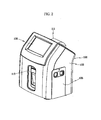
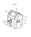
- FIG. 2 is perspective view illustrating an exemplary embodiment of the present invention
- FIG. 3 is an exploded view of the main part of FIG. 2 , illustrating the main configuration of an apparatus for analyzing blood chemistry.
- the apparatus for analyzing blood chemistry includes a main body 100 and a cartridge 300.
- the main body 100 as shown in FIG. 3 , includes an apparatus frame 101 forming a compartment therein and a case 103 combined with the apparatus frame 101 to form the outer shape.
- installing constituent elements to the apparatus frame 101 has the same meaning as installing the constituent element in the case 103, and the invention is not limited to those shown in the drawing.
- the apparatus frame 101 which is a framework of the apparatus for analyzing blood chemistry, has a space where the cartridge 300 is inserted and fixed to a predetermined position. Further, the apparatus frame 101 is provided with a cartridge door 105 that separates the cartridge 300 from the outside after the cartridge 300 is received.
- the cartridge door 105 is connected to the apparatus frame 101 by a common connecting means, such as a hinge, to be used to insert or draw out the cartridge 300.
- the cartridge door 105 is provided in this exemplary embodiment of the present invention; however, the cartridge door 105 may not be provided, depending on the design.
- a controller C and a data output unit 107 that is controlled by the controller C are connected to the apparatus frame 101.
- the data output unit 107 which is a device for display data processed by the controller C to allow a user to recognize the data, includes a common display 109 and a printer 111.
- the data output unit 107 is integrally formed with the main body 100.
- the main body 100 can be used without requiring a space when a medical team needs it.
- the data output unit 107 is not limited to the above, and may include a common data output port (not shown) that can transmit/ receive data in electric connection with a computer etc.
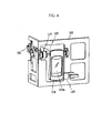
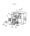
- An introducing unit opening/ closing cover 113 is hinged to the apparatus frame 101 such that it can rotate about a hinge shaft 115 as shown in FIG. 4 .
- the blood introducing unit opening/ closing cover 113 is provided with a magnifier 113a at the center.
- the magnifier 113a allows a user to easily observe components inside (a needle of the blood introducing unit that is described below).
- a power transmitting unit 117 that transmits torque from the hinge shaft 115 is fitted on the hinge shaft 115 of the blood introducing unit opening/ closing cover 113.
- the blood introducing unit opening/ closing cover 113 is connected to the hinge shaft 115 in this exemplary embodiment of the present invention, it is not limited to the above and may have other structures that can slide, depending on the design. Further, the blood introducing unit opening/ closing cover 113 may be a lever for the blood introducing unit that opens/ closes the blood introducing unit.
- the power transmitting unit 117 opens/closes the blood introducing unit of the cartridge 300, which is described below, using the torque due to the operation of the blood introducing unit opening/ closing cover 113.
- the power transmitting unit 117 includes a driving pulley 117a connected with the hinge shaft 115, a belt 117b transmitting torque of the driving pulley, and a driven pulley 117c rotated by the torque transmitted from the belt 117b.
- a connector 119 for actuating the blood introducing unit of the cartridge 300 is connected to the shaft of the driven pulley 117c. It is preferable that the connector 119 has a protrusion 119a at an end to transmit a driving force to the blood introducing unit.
- the power transmitting unit 117 is not limited to the structure described in this exemplary embodiment of the present invention, and may include gears without a belt and may be changed to have an appropriate structure for transmitting power with rectilinear motion, and may also include various configurations.
- the apparatus frame 101 is provided with a blood introducing unit opening/ closing cover sensor (121, shown in FIG. 4 ) which detects opening/closing of the blood introducing unit opening/closing cover 113 and transmits a signal to the controller C. Further, the apparatus frame 101 is provided with a lock 123 that fixes the blood introducing unit opening/closing cover 113.
- the lock 123 may be a common lock that is electrically controlled by the controller C to lock the blood introducing unit opening/closing cover 113.
- the apparatus frame 101 is provided with a driving unit 125 that supplies or blocks solutions, which are supplied to the cartridge 300, to a sensor card.
- the driving unit 125 is actuated by control of the controller (C).
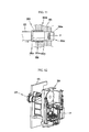
- the driving unit 125 includes solenoid unit 127 and movable members 129 disposed and moved in the solenoid units 127.
- An exemplary embodiment provided with four driving units 125 is possible as shown in FIG. 6 ; however, the invention is not limited thereto and other numbers of driving units may be disposed, if needed by design.
- the driving unit 125 is controlled by the controller C, and a structure that can linearly move through the rotational motion may be applied to an exemplary embodiment of the present invention, as long as the movable member 129 moves to push a pressing member, which is described below.
- the driving unit 125 is provided with a driving unit operation sensor 131, which detects the operation of the driving unit 125 and transmits a signal to the controller C, at one side.
- the apparatus frame 101 is provided with a cartridge door lock (133, shown in FIG. 1 ) which is controlled by the controller C to hold the cartridge 300 connected.
- a cartridge door lock sensor (135, shown in FIG. 1 ) that senses the locking status of the cartridge door lock 133 and transmits a signal to the controller may be provided.
- the apparatus frame 101 is provided with a solution transporting unit 137 that transports a solution by control of the controller C.
- the solution transporting unit 137 may have a structure including a rotator that is actuated by a motor and transports a solution while rotating in contact with a tubing.
- the solution transporting unit (137, shown in FIG. 1 ) is not limited to the above and other common means may be used, and a pump that can transport a solution may be used.
- the apparatus for analyzing blood chemistry is provided with a heater block (not shown) that has a heater for maintaining the temperature of the sensor card, which is described below. It is preferable that the heater is electrically connected to be actuated by the controller C.
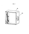
- FIG. 7 is a perspective view illustrating an exemplary embodiment of the invention
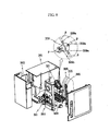
- FIG. 8 is an exploded perspective view of FIG. 7 , showing the cartridge 300.
- the cartridge 300 includes a cartridge case 301, a sensor card 303, solution bags 305, a waste container (307, shown in FIG. 1 ), solution tubing connectors 309, a solution valve unit 311, and a blood introducing unit 313.
- the cartridge case 301 is disposable and is replaced after being used for a predetermined period, and is formed of a substantially rectangular box with a space inside.
- the sensor card 303, the solution bags 305, the waste container 307, the solution tubing connectors 309, the solution valve unit 311, and the blood introducing unit 313 can be placed in the space of the cartridge case 301.
- the sensor card 303 measures the concentrations of electrolytes, the partial pressures of gases, and the concentrations of metabolites, or volume ratio of red blood cells contained in blood of a specimen passing through the sensor card, and then transmits the measured values to the controller C.
- a common sensor card can be used as the sensor card 303.
- the sensor card 303 is connected with the cartridge case 301 in this exemplary embodiment of the present invention, the present invention is not limited thereto and the sensor car may be connected to the apparatus frame 101, and any other sensor cards may also be possibly used if they can be used in the apparatus for analyzing blood chemistry.
- a variety of solutions are contained in the solution bags 305.
- the solutions are transported to the sensor card 303 and can be used as references for correcting the measured values of the concentrations of electrolytes, the partial pressures of gases, and the concentrations of metabolites the partial pressures of gases, and the concentrations of metabolites contained in blood.
- the solution bags 305 are connected to the solution connectors 309 through separate tubing (p).
- the solution bags 305 may be a common synthetic resin or aluminum bag.
- the cartridge case 301 is provided with the waste container 307 and a reference solution container 308.
- the waste container 307 is connected with the sensor card 303 by another tubing.
- the waste container 307 is a container where solutions used through the sensor card 303 are collected.
- the reference solution container 308 contains a solution having a function of QC (quality control) that periodically examines measurement of the sensor card 303. The values measured from the solution in the reference solution 308 are stored as data to allow a user to check the condition of the equipment.
- QC quality control
- the reference solution container 308 is connected with the sensor card 303 through another tubing (p). That is, the reference solution container 308, if needed, can directly supply the solution inside to the sensor card 303.
- the solution tubing connectors 309 are connected with the solution bags 305 through the tubing (p).
- the solution tubing connectors 309 each have inlets 309a circumferentially disposed, and through which the solutions flows inside.
- the inlets 309a converge to an outlet 309b disposed at the center.
- the inlets 309a correspond to the solution bags 305 and are connected with each other to always transport the solutions to the outlet 309b through the tubing (p). That is, the inlets 309a of the solution tubing connector 309 have a one-to-one connection with the solution bags 305 such that the solutions are always transported.
- the outlet 309b is connected to a tubing (p) such that the solutions flowing inside through the inlets 309a are transported to the blood introducing unit 313.
- the blood introducing unit 313 transports the specimen to the sensor card 303, or transports the solution passing through the solution tubing connector 309 or the reference solution to the sensor card 303.
- the blood introducing unit 313 includes a rotator 321 that is connected with the protrusion formed at the end of the connector 119 of the power transmitting unit 117, which was described in connection with the main body 100, and rotates, a needle 323 connected to the rotator 321, and another tubing (p) through which blood flowing inside through the needle 323 or solutions are transported to the sensor card 303.
- the blood introducing unit 313 has a structure in which the needle 323 protrudes outside or is received in a guide (325, shown in FIG.
- the blood introducing unit 313 may have a common structure that is known and used in the art.
- the structure of the blood introducing unit 313 described in this exemplary embodiment of the present invention is not limited to the above, and rectilinear motion, such as a slide, can be applied, in addition to the rotation of the rotator.
- the blood introducing unit 313 has a guide 325 with a semicircular groove inside the cartridge to be received at a predetermined position in the drawings, but is not limited thereto and may have rolling members, such as balls, and a plurality of grooves where the balls are inserted and fixed at predetermined positions such that the blood introducing unit 313 can move within a predetermined section.
- the tubings (p) are in close contact with the solution transporting unit 137 and the solution is transported by the operation of the transporting unit 137. It is preferable that the tubings (p) are made of synthetic resin having large elasticity.
- the solution valve unit 350 allows or blocks a flow of a solution to the sensor card 303 by opening or closing the tubings (p) disposed between the solution bags 305 and the solution tubing connectors 309.
- the solution valve unit 350 includes pressing members 351 and elastic members 353.
- the pressing members 351 each include a cylindrical body 351a, an extension 351b extending from the body 351a, and a head 351c formed at the end opposite to the extension 351b.
- a tubing insertion hole 351d is formed through the extension 351b at the center of the body 351a in the circumferential direction.
- the extension 351b may be relatively flat such that a slit 301a of the cartridge case 301 can be inserted and slide therein.
- the body 351a can be inserted and slid in a hole 301b of the case 301.
- the elastic member 353 is disposed in the separating direction from the case 301 while being elastically supported by the head 351c of the pressing member 351 and the case 301. It is preferable that the elastic member 353 is a compression coil spring.
- the elastic member 353 may be any one that can move the pressing member 351 in one direction. That is, the tubing (p) made of synthetic resin is pushed in the tubing insertion hole 351d of the pressing member 351 when an elastic force is applied by the elastic member 353, such that the movement of the solutions is restricted. As the pressing members 351 are pressed by the movable members 129 of the driving unit 125 and the elastic members 353 are pushed, the pressure applied to the tubing (p) is released and the solutions correspondingly flow.
- the controller that receives and processes a signal generated from the sensor card and the controller that controls the solution transporting unit and driving unit are electrically separated. That is, it is preferable that independent power is provided for the processing unit of the signal detected by the sensor card and an actuating unit of a pump-solenoid to avoid electrical interference, and independent isolation circuits are applied to the input/output signal unit.
- the signals detected in the controller which receives and processes the signals generated from the sensor card, are electrically classified according to the types.
- electrical isolation circuits are applied to avoid interference between the signals detected by the sensor card, that is, independent sensing signals for each measuring item of electrolytes, the partial pressures of gases, and the concentrations of metabolites, and volume ratio of the red blood cells, or electrical interference.
- a user opens the cartridge door 105 and inserts the cartridge 300 into the main body 100.
- the user then closes the cartridge door 105.
- the controller C checks whether the sensor card 303 is normally inserted in the cartridge 300 (S1).
- the controller C makes the lock for the blood introducing unit opening/closing cover 123 normally lock the blood introducing unit opening/closing cover 113.
- the controller C receives a signal generated by the blood introducing unit opening/closing cover sensor 121 detecting that the lock for the blood introducing unit opening/closing cover 123 is locked (S3). Further, the controller C locks the cartridge door 105 by the cartridge door lock 133.
- the controller C receives a signal generated by the cartridge door lock sensor 135 detecting that the cartridge door lock 133 is locked (S5).
- a preliminary warm-up for analysis is performed after steps S1, S3, and S5 (S7).
- reference data is first measured by alternatively transporting the solutions in the solution bags 305. The reference data is used for correcting data measured from blood in a next process. Transportation of the solutions is described hereafter.
- the controller C controls the driving unit 125 to control the movable member 129 that can open the tubing (p) connected to a desired solution bagl 305.
- the movable member 129 as shown in FIG. 6 , supplies a solution and presses the pressing member 351 of the block unit 350 while moving in the arrow direction.
- the pressing member 351 correspondingly moves in the arrow direction against the elastic force of the elastic member 353.
- the pressing member 351 releases the pressure applied to the tubing (p).
- the solution is transported through the tubing (p).
- the solution is transported to the sensor card 303 through the blood introducing unit 313.
- An electric signal generated by the transportation of the solution to the sensor card 303 is transmitted to the controller C.
- the sensor card 303 detects electric signals of the solutions in the other solution bags 305, if needed.
- the solution supplied to the sensor card 303 is transported to the waste container 307 and stored therein.
- the controller C controls the lock for the blood introducing unit opening/closing cover 123 to be open.
- the user softly pulls the blood introducing unit opening/closing cover 113 by hand.
- the blood introducing unit opening/closing cover 113 correspondingly turns and torque is transmitted through the power transmitting unit 117. That is, as the blood introducing unit opening/closing cover 113 rotates, the hinge shaft 115 rotates, and as the hinge shaft 115 rotates, the torque of the driving pulley 117a is transmitted to the driven pulley 117c through the belt 117b.
- the torque of the driven pulley 117c is transmitted to the connector 119.
- the torque transmitted to the connector 119 rotates the rotator (321, shown in FIG. 12 ) of the cartridge 300. As the rotator rotates 321, the needle 323 rotates and the end protrudes outside.
- the controller C controls the solution transporting unit 137 to transport the blood sample into the sensor card 303.
- the controller C informs the user that he/she can close the blood introducing unit opening/closing cover 113 through the display.
- the user softly closes the blood introducing unit opening/closing cover 113.
- the controller C can maintain the lock by actuating the lock for the blood introducing unit opening/ closing cover 123.
- the sensor card 303 detects electrical signals corresponding to the concentrations of electrolytes, the partial pressures of gases, and the concentrations of metabolites, or the volume ratio of the red blood cells in the blood, and transmits the signals to the controller C (S9).
- the controller C calculates the result of the analysis of the measured substances on the basis of the measured data from the electric signals of the solutions in the solution bags 305 (S9), and can store the data in a storage (not shown) or output it to the data output unit 107. Thereafter, the sensor card 303 is washed by the solution in the solution bags 305 (S13). Washing the sensor card 303 is done when the solution in the solution bags 305 flows into the waste container 307 through the sensor card 303 by the solution transmitting unit 137 actuated by the controller C. The controller C performs analysis examination (S15).
- the solution bags 305 have one-to-one connection with the solution tubing connectors 309, even though different solutions are repeatedly passed, they do not leak outside. Accordingly, it is possible to improve accuracy of the sensed data and the commercial value. Further, according to an exemplary embodiment of the present invention, it is possible to transport two or more solutions by actuating two or more movable members, such that availability can be improved. Further, according to an exemplary embodiment of the present invention, it is possible to achieve an apparatus for analyzing blood chemistry that has a structure that uses manual sampling, by using a cartridge including a sensor card, tubing, and a solution, such that the electrically-actuated units are not needed. Therefore, it is possible to reduce manufacturing cost and power consumption.
- the apparatus has a simple structure, such that a medical team can conveniently use the apparatus anywhere they need without requiring a space.
Landscapes
- Health & Medical Sciences (AREA)
- Life Sciences & Earth Sciences (AREA)
- Engineering & Computer Science (AREA)
- Biomedical Technology (AREA)
- Chemical & Material Sciences (AREA)
- Physics & Mathematics (AREA)
- Hematology (AREA)
- Immunology (AREA)
- Analytical Chemistry (AREA)
- Pathology (AREA)
- General Physics & Mathematics (AREA)
- General Health & Medical Sciences (AREA)
- Biochemistry (AREA)
- Food Science & Technology (AREA)
- Medicinal Chemistry (AREA)
- Molecular Biology (AREA)
- Ecology (AREA)
- Biophysics (AREA)
- Urology & Nephrology (AREA)
- Hydrology & Water Resources (AREA)
- Investigating Or Analysing Biological Materials (AREA)
- Automatic Analysis And Handling Materials Therefor (AREA)
Claims (10)
- Vorrichtung zum Analysieren der Blutchemie, umfassend:einen Vorrichtungsrahmen (101) mit einem Fach,eine Kartusche (300), die in das Fach des Vorrichtungsrahmens (101) eingesteckt wird und Lösungsbeutel (305) mit darin enthaltenen Lösungen, eine Ventileinheit (311) für die Lösung zum Gestatten oder Blockieren des Flusses der Lösung und eine Bluteinführeinheit (313) umfasst,eine Sensorkarte (303), die in der Kartusche oder in dem Vorrichtungsrahmen (101) angeordnet ist, um die Konzentrationen von Elektrolyten, die Partialdrücke von Gasen und die Konzentrationen von Metaboliten oder das Volumenverhältnis der roten Blutkörperchen in einem durch die Bluteinführeinheit (313) zugeführten Blut zu messen,eine Steuereinrichtung (C) zum Empfangen von durch die Sensorkarte (303) erzeugten Signalen und zum Verarbeiten der Signale,eine Leistungsübertragungseinheit (117), die an dem Vorrichtungsrahmen (101) vorgesehen ist und die Leistung auf einen Hebel (113) überträgt, um die Bluteinführeinheit (313) zu öffnen oder zu schließen,eine Lösungstransporteinheit, die in dem Vorrichtungsrahmen (101) vorgesehen ist und die Lösungen in den Lösungsbeuteln transportiert,weiterhin gekennzeichnet durchden Hebel (113) für die Bluteinführeinheit (313), der mit dem Vorrichtungsrahmen (101) verbunden ist, wobei der Hebel (113) eine Abdeckung für die Bluteinführeinheit (313) ist,wobei die Abdeckung in ihrer Mitte mit einem Vergrößerungsglas (113a) versehen ist, undwenigstens eine Antriebseinheit (125) zum Betätigen der Ventileinheit für die Lösung der Kartusche durch die Steuereinrichtung (C) und zum öffnen oder Schließen der Rohrleitungen für den Fluss der Lösungen.
- Vorrichtung zum Analysieren der Blutchemie nach Anspruch 1, wobei:
die Antriebseinheiten (125) jeweils umfassen:eine Solenoideinheit (127), die durch die Steuereinrichtung (C) gesteuert wird, undein bewegliches Glied (129), das durch eine elektrische Betätigung der Solenoideinheit (127) bewegt werden kann. - Vorrichtung zum Analysieren der Blutchemie nach Anspruch 1, des Weiteren umfassend:Datenausgabeeinheiten (107) zum Ausgeben von durch die Steuereinrichtung (C) verarbeiteten Daten,wobei die Datenausgabeeinheiten (107) eine Anzeige (109) und einen Drucker (111) umfassen, die jeweils in der Vorrichtung integriert sind.
- Vorrichtung zum Analysieren der Blutchemie nach Anspruch 1, wobei:ein Teil der Steuereinrichtung (C) zum Empfangen von durch die Sensorkarte (303) erzeugten Signalen und zum Verarbeiten der Signale, elektrisch von einem Teil der Steuereinrichtung (C) zum Steuern der Lösungstransporteinheit (137) und der Antriebseinheiten (125) isoliert ist.
- Vorrichtung zum Analysieren der Blutchemie nach Anspruch 1, wobei:die durch die Sensorkarte (303) erzeugten und durch die Steuereinrichtung (C) empfangenen und verarbeiteten Signale elektrisch zwischen den Signalen in Abhängigkeit von dem Typ der Signale isoliert sind.
- Vorrichtung zum Analysieren der Blutchemie nach Anspruch 1, wobei der Vorrichtungsrahmen (101) mit einer Kartuschentür (105) versehen ist, die durch ein Scharnier an dem Vorrichtungsrahmen (101) befestigt ist und mit einer Kartuschentürverriegelung (133) zum Verriegeln der Kartuschentür (105) an dem Vorrichtungsrahmen (101) und mit einem Kartuschentür-Verriegelungssensor (135) zum Erfassen des Verriegelungsstatus der Türverriegelung (133) und zum Senden eines Erfassungssignals an die Steuereinrichtung (C) ausgestattet ist.
- Vorrichtung zum Analysieren der Blutchemie nach Anspruch 1, wobei der Vorrichtungsrahmen (101) mit einer Hebelverriegelung zum Verriegeln des Hebels für die Bluteinführeinheit (313) und mit einer Erfassungseinheit zum Erfassen des Verriegelungsstatus der Hebelverriegelung und zum Senden eines Erfassungssignals an die Steuereinrichtung (C) versehen ist.
- Vorrichtung zum Analysieren der Blutchemie nach Anspruch 1, wobei der Vorrichtungsrahmen (101) mit einer Erfassungseinheit zum Erfassen des Betriebs der Antriebseinheit (125) und zum Senden eines Erfassungssignals an die Steuereinrichtung (C) versehen ist.
- Vorrichtung zum Analysieren der Blutchemie nach Anspruch 1, wobei der Vorrichtungsrahmen (101) mit einem Heizerblock versehen ist, der mit einem Heizer zum Aufrechterhalten einer konstanten Temperatur der Sensorkarte (303) ausgestattet ist.
- Vorrichtung zum Analysieren der Blutchemie nach Anspruch 1, wobei die Kartusche (300) mit einem Abfallbehälter (307) versehen ist, der mit der Sensorkarte (303) über eine Rohrverbindung verbunden ist.
Applications Claiming Priority (2)
| Application Number | Priority Date | Filing Date | Title |
|---|---|---|---|
| KR1020070110990A KR100886914B1 (ko) | 2007-11-01 | 2007-11-01 | 혈액 분석 장치용 카트리지 및 이를 이용한 혈액 분석 장치 |
| PCT/KR2008/006429 WO2009057969A1 (en) | 2007-11-01 | 2008-10-30 | Cartridge for apparatus for chemically analyzing blood and apparatus using the same |
Publications (3)
| Publication Number | Publication Date |
|---|---|
| EP2205969A1 EP2205969A1 (de) | 2010-07-14 |
| EP2205969A4 EP2205969A4 (de) | 2013-03-13 |
| EP2205969B1 true EP2205969B1 (de) | 2015-04-15 |
Family
ID=40591251
Family Applications (1)
| Application Number | Title | Priority Date | Filing Date |
|---|---|---|---|
| EP08843727.2A Active EP2205969B1 (de) | 2007-11-01 | 2008-10-30 | Kartusche für eine vorrichtung zur chemischen blutanalyse und vorrichtung mit dieser kartusche |
Country Status (6)
| Country | Link |
|---|---|
| US (1) | US8940233B2 (de) |
| EP (1) | EP2205969B1 (de) |
| JP (1) | JP5085740B2 (de) |
| KR (1) | KR100886914B1 (de) |
| CN (1) | CN101842703B (de) |
| WO (1) | WO2009057969A1 (de) |
Families Citing this family (15)
| Publication number | Priority date | Publication date | Assignee | Title |
|---|---|---|---|---|
| KR101057148B1 (ko) * | 2009-09-25 | 2011-08-17 | 주식회사 아이센스 | 휴대용 혈액 분석 장치 |
| US9625465B2 (en) | 2012-05-15 | 2017-04-18 | Defined Diagnostics, Llc | Clinical diagnostic systems |
| US9213043B2 (en) | 2012-05-15 | 2015-12-15 | Wellstat Diagnostics, Llc | Clinical diagnostic system including instrument and cartridge |
| US9075042B2 (en) | 2012-05-15 | 2015-07-07 | Wellstat Diagnostics, Llc | Diagnostic systems and cartridges |
| KR102249318B1 (ko) * | 2013-11-22 | 2021-05-07 | 삼성전자주식회사 | 유체 시료 검사장치 및 그 제어방법 |
| KR20150090582A (ko) * | 2014-01-29 | 2015-08-06 | 삼성전자주식회사 | 시료 검사장치 및 그 제어방법 |
| DE102015103937A1 (de) * | 2015-03-17 | 2016-09-22 | B. Braun Avitum Ag | Blutbehandlungsgerät mit separatem Türabteil |
| CN105319216B (zh) * | 2015-11-03 | 2019-03-05 | 中山市生科试剂仪器有限公司 | 一种血液自动分析仪 |
| WO2022040376A2 (en) * | 2020-08-21 | 2022-02-24 | Verthermia Acquisition, Inc. | Improved method and system for controlled hyperthermia |
| CN114397467B (zh) * | 2022-01-11 | 2024-08-23 | 广州万孚生物技术股份有限公司 | 血气分析仪 |
| KR20240157243A (ko) | 2023-04-25 | 2024-11-01 | 주식회사 아이센스 | 혈액 분석용 카트리지 조립체 및 이를 포함하는 혈액 분석 장치 |
| KR20240157244A (ko) | 2023-04-25 | 2024-11-01 | 주식회사 아이센스 | 혈액 분석용 카트리지 조립체 및 이를 포함하는 혈액 분석 장치 |
| KR20250038913A (ko) | 2023-09-13 | 2025-03-20 | 주식회사 아이센스 | 혈액 분석 장치 |
| KR20250039586A (ko) | 2023-09-14 | 2025-03-21 | 주식회사 아이센스 | 혈액 분석 장치 |
| WO2025245754A1 (zh) * | 2024-05-29 | 2025-12-04 | 深圳市理邦精密仪器股份有限公司 | 用于血气分析仪的试剂盒以及血气分析仪 |
Family Cites Families (22)
| Publication number | Priority date | Publication date | Assignee | Title |
|---|---|---|---|---|
| CA1153580A (en) * | 1979-10-29 | 1983-09-13 | Jeremy R. Hill | Liquid conductivity measuring system and sample cards therefor |
| US4786394A (en) * | 1985-08-29 | 1988-11-22 | Diamond Sensor Systems, Inc. | Apparatus for chemical measurement of blood characteristics |
| US4849340A (en) * | 1987-04-03 | 1989-07-18 | Cardiovascular Diagnostics, Inc. | Reaction system element and method for performing prothrombin time assay |
| DE3938559A1 (de) * | 1989-11-21 | 1991-05-23 | Boehringer Mannheim Gmbh | Reagenzbevorratungssystem fuer ein medizinisches analysegeraet |
| US5325853A (en) * | 1992-09-02 | 1994-07-05 | Diametrics Medical, Inc. | Calibration medium containment system |
| FR2723735B1 (fr) * | 1994-08-18 | 1996-10-31 | Abx Sa | Boitier a branchement automatique pour distribution de reactifs dans un appareil notamment un analyseur hematologique. |
| WO1997008561A1 (en) * | 1995-08-30 | 1997-03-06 | Radiometer Medical A/S | Automatic introduction of reference fluids in an apparatus for analysis of physiological fluids |
| US6066243A (en) * | 1997-07-22 | 2000-05-23 | Diametrics Medical, Inc. | Portable immediate response medical analyzer having multiple testing modules |
| JP4446592B2 (ja) * | 2000-12-25 | 2010-04-07 | シスメックス株式会社 | 液体試料測定ユニット及びそれを備えた自動液体試料分析装置 |
| KR100893275B1 (ko) * | 2001-03-29 | 2009-04-17 | 라이프스캔 스코트랜드 리미티드 | 일체식 샘플 시험용 계측기 |
| US6890291B2 (en) * | 2001-06-25 | 2005-05-10 | Mission Medical, Inc. | Integrated automatic blood collection and processing unit |
| JP2003075034A (ja) * | 2001-08-31 | 2003-03-12 | Hoshizaki Electric Co Ltd | オーガ式製氷機の異常検出装置 |
| US20030224523A1 (en) | 2002-05-30 | 2003-12-04 | Thornberg John Herbert | Cartridge arrangement, fluid analyzer arrangement, and methods |
| JP2004163319A (ja) * | 2002-11-14 | 2004-06-10 | Sysmex Corp | 液体容器ユニットおよび接続機構 |
| JP3705438B2 (ja) * | 2003-09-09 | 2005-10-12 | 理研計器株式会社 | 流体注入機構 |
| EP1543877B1 (de) * | 2003-12-16 | 2010-03-17 | Sysmex Corporation | Analysevorrichtung und Reagenzbehälter |
| JP4482926B2 (ja) * | 2004-02-20 | 2010-06-16 | 富士フイルム株式会社 | 科学現象の評価装置、拡散速度測定実験装置、及びその製造方法 |
| JP2005249636A (ja) * | 2004-03-05 | 2005-09-15 | Saginomiya Seisakusho Inc | 成分測定・分析装置 |
| JP2007130994A (ja) * | 2005-10-12 | 2007-05-31 | Seiko Epson Corp | 弁開閉装置、液体供給装置及び液体噴射装置 |
| DE102005057191B4 (de) * | 2005-11-29 | 2011-12-08 | Leica Biosystems Nussloch Gmbh | Gewebeprozessor |
| JP2007248405A (ja) * | 2006-03-20 | 2007-09-27 | Horiba Ltd | 血液分析装置 |
| KR100873915B1 (ko) * | 2007-11-01 | 2008-12-12 | 주식회사 아이센스 | 혈액 분석 장치용 용액 용기 |
-
2007
- 2007-11-01 KR KR1020070110990A patent/KR100886914B1/ko active Active
-
2008
- 2008-10-30 CN CN2008801137894A patent/CN101842703B/zh active Active
- 2008-10-30 WO PCT/KR2008/006429 patent/WO2009057969A1/en not_active Ceased
- 2008-10-30 EP EP08843727.2A patent/EP2205969B1/de active Active
- 2008-10-30 JP JP2010531965A patent/JP5085740B2/ja active Active
- 2008-10-30 US US12/739,686 patent/US8940233B2/en active Active
Also Published As
| Publication number | Publication date |
|---|---|
| CN101842703B (zh) | 2013-04-10 |
| JP5085740B2 (ja) | 2012-11-28 |
| EP2205969A1 (de) | 2010-07-14 |
| KR100886914B1 (ko) | 2009-03-09 |
| CN101842703A (zh) | 2010-09-22 |
| JP2011503538A (ja) | 2011-01-27 |
| US20110195490A1 (en) | 2011-08-11 |
| WO2009057969A1 (en) | 2009-05-07 |
| EP2205969A4 (de) | 2013-03-13 |
| US8940233B2 (en) | 2015-01-27 |
Similar Documents
| Publication | Publication Date | Title |
|---|---|---|
| US8940233B2 (en) | Cartridge for apparatus for chemically analyzing blood and apparatus using the same | |
| US9110044B2 (en) | System for the integrated and automated analysis of DNA or protein and method for operating said type of system | |
| US8747747B2 (en) | Reader devices for manipulating multi-fluidic cartridges for sample analysis | |
| US8826752B2 (en) | Multi-fluidic cartridges for sample analysis and methods for using same | |
| CN219996955U (zh) | 样本分析装置及血气分析设备 | |
| KR102720793B1 (ko) | 서열분석 디바이스 | |
| CN101203754A (zh) | 用于确定分析浓度的测试装置 | |
| WO2023134622A1 (en) | Blood gas analyzer | |
| TW201905434A (zh) | 用於預處理尤其是一生物樣本之方法、萃取工具、施配工具及套件 | |
| JP3834357B2 (ja) | 小型分析装置及びその駆動方法 | |
| CN109557295A (zh) | 血气测试方法、血气测试主机、试剂包以及血气测试卡 | |
| US10816563B2 (en) | System for operating a system for the integrated and automated analysis of DNA or protein | |
| EP4707800A1 (de) | Blutanalysekartuschenanordnung und blutanalysevorrichtung damit | |
| EP4707799A1 (de) | Kartuschenanordnung zur analyse von blut und blutanalysevorrichtung damit | |
| US9476896B2 (en) | Sample inspection apparatus and control method thereof | |
| KR20200056390A (ko) | 바이오 프로세스 및 기타 프로세스를 위한 장치 및 방법 | |
| US20250058314A1 (en) | Apparatus comprising cartridge with absorbing element | |
| US20230036668A1 (en) | Sample test cassette and analyte test system utilizing the same | |
| EP3523031B1 (de) | Analysevorrichtung, kassette und verfahren zur analyse einer probe | |
| CN119595921A (zh) | 一种自动检测生化分析仪 | |
| CN111198268A (zh) | 一种生物流体样本检测试剂盒及其检测系统与应用 |
Legal Events
| Date | Code | Title | Description |
|---|---|---|---|
| PUAI | Public reference made under article 153(3) epc to a published international application that has entered the european phase |
Free format text: ORIGINAL CODE: 0009012 |
|
| 17P | Request for examination filed |
Effective date: 20100423 |
|
| AK | Designated contracting states |
Kind code of ref document: A1 Designated state(s): AT BE BG CH CY CZ DE DK EE ES FI FR GB GR HR HU IE IS IT LI LT LU LV MC MT NL NO PL PT RO SE SI SK TR |
|
| AX | Request for extension of the european patent |
Extension state: AL BA MK RS |
|
| DAX | Request for extension of the european patent (deleted) | ||
| RIC1 | Information provided on ipc code assigned before grant |
Ipc: G01N 33/49 20060101AFI20130131BHEP |
|
| A4 | Supplementary search report drawn up and despatched |
Effective date: 20130207 |
|
| RIC1 | Information provided on ipc code assigned before grant |
Ipc: G01N 33/49 20060101AFI20130201BHEP |
|
| 17Q | First examination report despatched |
Effective date: 20131025 |
|
| GRAP | Despatch of communication of intention to grant a patent |
Free format text: ORIGINAL CODE: EPIDOSNIGR1 |
|
| RIN1 | Information on inventor provided before grant (corrected) |
Inventor name: LEE, HEEJUN Inventor name: KANG, TAE YOUNG Inventor name: SHIN, JUNGWON Inventor name: NAM, HAKHYUN Inventor name: CHA, GEUN SIG Inventor name: HA, JEONGHAN |
|
| INTG | Intention to grant announced |
Effective date: 20141028 |
|
| GRAS | Grant fee paid |
Free format text: ORIGINAL CODE: EPIDOSNIGR3 |
|
| GRAA | (expected) grant |
Free format text: ORIGINAL CODE: 0009210 |
|
| AK | Designated contracting states |
Kind code of ref document: B1 Designated state(s): AT BE BG CH CY CZ DE DK EE ES FI FR GB GR HR HU IE IS IT LI LT LU LV MC MT NL NO PL PT RO SE SI SK TR |
|
| REG | Reference to a national code |
Ref country code: GB Ref legal event code: FG4D Ref country code: CH Ref legal event code: EP |
|
| REG | Reference to a national code |
Ref country code: IE Ref legal event code: FG4D |
|
| REG | Reference to a national code |
Ref country code: AT Ref legal event code: REF Ref document number: 722271 Country of ref document: AT Kind code of ref document: T Effective date: 20150515 |
|
| REG | Reference to a national code |
Ref country code: DE Ref legal event code: R096 Ref document number: 602008037725 Country of ref document: DE Effective date: 20150528 |
|
| REG | Reference to a national code |
Ref country code: NL Ref legal event code: T3 |
|
| REG | Reference to a national code |
Ref country code: AT Ref legal event code: MK05 Ref document number: 722271 Country of ref document: AT Kind code of ref document: T Effective date: 20150415 |
|
| REG | Reference to a national code |
Ref country code: LT Ref legal event code: MG4D |
|
| PG25 | Lapsed in a contracting state [announced via postgrant information from national office to epo] |
Ref country code: HR Free format text: LAPSE BECAUSE OF FAILURE TO SUBMIT A TRANSLATION OF THE DESCRIPTION OR TO PAY THE FEE WITHIN THE PRESCRIBED TIME-LIMIT Effective date: 20150415 Ref country code: ES Free format text: LAPSE BECAUSE OF FAILURE TO SUBMIT A TRANSLATION OF THE DESCRIPTION OR TO PAY THE FEE WITHIN THE PRESCRIBED TIME-LIMIT Effective date: 20150415 Ref country code: LT Free format text: LAPSE BECAUSE OF FAILURE TO SUBMIT A TRANSLATION OF THE DESCRIPTION OR TO PAY THE FEE WITHIN THE PRESCRIBED TIME-LIMIT Effective date: 20150415 Ref country code: FI Free format text: LAPSE BECAUSE OF FAILURE TO SUBMIT A TRANSLATION OF THE DESCRIPTION OR TO PAY THE FEE WITHIN THE PRESCRIBED TIME-LIMIT Effective date: 20150415 Ref country code: NO Free format text: LAPSE BECAUSE OF FAILURE TO SUBMIT A TRANSLATION OF THE DESCRIPTION OR TO PAY THE FEE WITHIN THE PRESCRIBED TIME-LIMIT Effective date: 20150715 Ref country code: PT Free format text: LAPSE BECAUSE OF FAILURE TO SUBMIT A TRANSLATION OF THE DESCRIPTION OR TO PAY THE FEE WITHIN THE PRESCRIBED TIME-LIMIT Effective date: 20150817 |
|
| REG | Reference to a national code |
Ref country code: FR Ref legal event code: PLFP Year of fee payment: 8 |
|
| PG25 | Lapsed in a contracting state [announced via postgrant information from national office to epo] |
Ref country code: GR Free format text: LAPSE BECAUSE OF FAILURE TO SUBMIT A TRANSLATION OF THE DESCRIPTION OR TO PAY THE FEE WITHIN THE PRESCRIBED TIME-LIMIT Effective date: 20150716 Ref country code: AT Free format text: LAPSE BECAUSE OF FAILURE TO SUBMIT A TRANSLATION OF THE DESCRIPTION OR TO PAY THE FEE WITHIN THE PRESCRIBED TIME-LIMIT Effective date: 20150415 Ref country code: IS Free format text: LAPSE BECAUSE OF FAILURE TO SUBMIT A TRANSLATION OF THE DESCRIPTION OR TO PAY THE FEE WITHIN THE PRESCRIBED TIME-LIMIT Effective date: 20150815 Ref country code: LV Free format text: LAPSE BECAUSE OF FAILURE TO SUBMIT A TRANSLATION OF THE DESCRIPTION OR TO PAY THE FEE WITHIN THE PRESCRIBED TIME-LIMIT Effective date: 20150415 |
|
| REG | Reference to a national code |
Ref country code: DE Ref legal event code: R097 Ref document number: 602008037725 Country of ref document: DE |
|
| PG25 | Lapsed in a contracting state [announced via postgrant information from national office to epo] |
Ref country code: DK Free format text: LAPSE BECAUSE OF FAILURE TO SUBMIT A TRANSLATION OF THE DESCRIPTION OR TO PAY THE FEE WITHIN THE PRESCRIBED TIME-LIMIT Effective date: 20150415 Ref country code: EE Free format text: LAPSE BECAUSE OF FAILURE TO SUBMIT A TRANSLATION OF THE DESCRIPTION OR TO PAY THE FEE WITHIN THE PRESCRIBED TIME-LIMIT Effective date: 20150415 |
|
| PLBE | No opposition filed within time limit |
Free format text: ORIGINAL CODE: 0009261 |
|
| STAA | Information on the status of an ep patent application or granted ep patent |
Free format text: STATUS: NO OPPOSITION FILED WITHIN TIME LIMIT |
|
| PG25 | Lapsed in a contracting state [announced via postgrant information from national office to epo] |
Ref country code: SK Free format text: LAPSE BECAUSE OF FAILURE TO SUBMIT A TRANSLATION OF THE DESCRIPTION OR TO PAY THE FEE WITHIN THE PRESCRIBED TIME-LIMIT Effective date: 20150415 Ref country code: PL Free format text: LAPSE BECAUSE OF FAILURE TO SUBMIT A TRANSLATION OF THE DESCRIPTION OR TO PAY THE FEE WITHIN THE PRESCRIBED TIME-LIMIT Effective date: 20150415 Ref country code: RO Free format text: LAPSE BECAUSE OF NON-PAYMENT OF DUE FEES Effective date: 20150415 Ref country code: CZ Free format text: LAPSE BECAUSE OF FAILURE TO SUBMIT A TRANSLATION OF THE DESCRIPTION OR TO PAY THE FEE WITHIN THE PRESCRIBED TIME-LIMIT Effective date: 20150415 |
|
| 26N | No opposition filed |
Effective date: 20160118 |
|
| PG25 | Lapsed in a contracting state [announced via postgrant information from national office to epo] |
Ref country code: LU Free format text: LAPSE BECAUSE OF FAILURE TO SUBMIT A TRANSLATION OF THE DESCRIPTION OR TO PAY THE FEE WITHIN THE PRESCRIBED TIME-LIMIT Effective date: 20151030 Ref country code: SI Free format text: LAPSE BECAUSE OF FAILURE TO SUBMIT A TRANSLATION OF THE DESCRIPTION OR TO PAY THE FEE WITHIN THE PRESCRIBED TIME-LIMIT Effective date: 20150415 |
|
| REG | Reference to a national code |
Ref country code: CH Ref legal event code: PL |
|
| GBPC | Gb: european patent ceased through non-payment of renewal fee |
Effective date: 20151030 |
|
| PG25 | Lapsed in a contracting state [announced via postgrant information from national office to epo] |
Ref country code: MC Free format text: LAPSE BECAUSE OF FAILURE TO SUBMIT A TRANSLATION OF THE DESCRIPTION OR TO PAY THE FEE WITHIN THE PRESCRIBED TIME-LIMIT Effective date: 20150415 |
|
| REG | Reference to a national code |
Ref country code: NL Ref legal event code: MM Effective date: 20151101 |
|
| REG | Reference to a national code |
Ref country code: IE Ref legal event code: MM4A |
|
| PG25 | Lapsed in a contracting state [announced via postgrant information from national office to epo] |
Ref country code: CH Free format text: LAPSE BECAUSE OF NON-PAYMENT OF DUE FEES Effective date: 20151031 Ref country code: LI Free format text: LAPSE BECAUSE OF NON-PAYMENT OF DUE FEES Effective date: 20151031 Ref country code: GB Free format text: LAPSE BECAUSE OF NON-PAYMENT OF DUE FEES Effective date: 20151030 |
|
| PG25 | Lapsed in a contracting state [announced via postgrant information from national office to epo] |
Ref country code: BE Free format text: LAPSE BECAUSE OF FAILURE TO SUBMIT A TRANSLATION OF THE DESCRIPTION OR TO PAY THE FEE WITHIN THE PRESCRIBED TIME-LIMIT Effective date: 20150415 Ref country code: NL Free format text: LAPSE BECAUSE OF NON-PAYMENT OF DUE FEES Effective date: 20151101 |
|
| REG | Reference to a national code |
Ref country code: FR Ref legal event code: PLFP Year of fee payment: 9 |
|
| PG25 | Lapsed in a contracting state [announced via postgrant information from national office to epo] |
Ref country code: IE Free format text: LAPSE BECAUSE OF NON-PAYMENT OF DUE FEES Effective date: 20151030 |
|
| PG25 | Lapsed in a contracting state [announced via postgrant information from national office to epo] |
Ref country code: BG Free format text: LAPSE BECAUSE OF FAILURE TO SUBMIT A TRANSLATION OF THE DESCRIPTION OR TO PAY THE FEE WITHIN THE PRESCRIBED TIME-LIMIT Effective date: 20150415 Ref country code: HU Free format text: LAPSE BECAUSE OF FAILURE TO SUBMIT A TRANSLATION OF THE DESCRIPTION OR TO PAY THE FEE WITHIN THE PRESCRIBED TIME-LIMIT; INVALID AB INITIO Effective date: 20081030 |
|
| PG25 | Lapsed in a contracting state [announced via postgrant information from national office to epo] |
Ref country code: SE Free format text: LAPSE BECAUSE OF FAILURE TO SUBMIT A TRANSLATION OF THE DESCRIPTION OR TO PAY THE FEE WITHIN THE PRESCRIBED TIME-LIMIT Effective date: 20150415 Ref country code: CY Free format text: LAPSE BECAUSE OF FAILURE TO SUBMIT A TRANSLATION OF THE DESCRIPTION OR TO PAY THE FEE WITHIN THE PRESCRIBED TIME-LIMIT Effective date: 20150415 |
|
| REG | Reference to a national code |
Ref country code: DE Ref legal event code: R082 Ref document number: 602008037725 Country of ref document: DE |
|
| PG25 | Lapsed in a contracting state [announced via postgrant information from national office to epo] |
Ref country code: TR Free format text: LAPSE BECAUSE OF FAILURE TO SUBMIT A TRANSLATION OF THE DESCRIPTION OR TO PAY THE FEE WITHIN THE PRESCRIBED TIME-LIMIT Effective date: 20150415 Ref country code: MT Free format text: LAPSE BECAUSE OF FAILURE TO SUBMIT A TRANSLATION OF THE DESCRIPTION OR TO PAY THE FEE WITHIN THE PRESCRIBED TIME-LIMIT Effective date: 20150415 |
|
| REG | Reference to a national code |
Ref country code: FR Ref legal event code: PLFP Year of fee payment: 10 |
|
| REG | Reference to a national code |
Ref country code: FR Ref legal event code: PLFP Year of fee payment: 11 |
|
| PGFP | Annual fee paid to national office [announced via postgrant information from national office to epo] |
Ref country code: IT Payment date: 20250922 Year of fee payment: 18 |
|
| PGFP | Annual fee paid to national office [announced via postgrant information from national office to epo] |
Ref country code: FR Payment date: 20250908 Year of fee payment: 18 |
|
| PGFP | Annual fee paid to national office [announced via postgrant information from national office to epo] |
Ref country code: DE Payment date: 20250902 Year of fee payment: 18 |