EP2205516B1 - Step for a moving staircase or pallet for and moving staircase with such a step or conveyor with such a pallet and method for manufacturing such a step or pallet - Google Patents
Step for a moving staircase or pallet for and moving staircase with such a step or conveyor with such a pallet and method for manufacturing such a step or pallet Download PDFInfo
- Publication number
- EP2205516B1 EP2205516B1 EP08838320.3A EP08838320A EP2205516B1 EP 2205516 B1 EP2205516 B1 EP 2205516B1 EP 08838320 A EP08838320 A EP 08838320A EP 2205516 B1 EP2205516 B1 EP 2205516B1
- Authority
- EP
- European Patent Office
- Prior art keywords
- cheek
- plate
- cheeks
- skeleton
- roller
- Prior art date
- Legal status (The legal status is an assumption and is not a legal conclusion. Google has not performed a legal analysis and makes no representation as to the accuracy of the status listed.)
- Active
Links
Images


Classifications
-
- B—PERFORMING OPERATIONS; TRANSPORTING
- B66—HOISTING; LIFTING; HAULING
- B66B—ELEVATORS; ESCALATORS OR MOVING WALKWAYS
- B66B23/00—Component parts of escalators or moving walkways
- B66B23/08—Carrying surfaces
- B66B23/12—Steps
Definitions
- the invention relates to a step for an escalator or pallet for a moving walkway comprising a step skeleton or pallet skeleton as a support for at least one tread element according to the definition of the independent claim.
- the step is skeleton-like and consists essentially of an angled support plate, which forms the side parts and the front part. Arranged on the support plate is an angle at which the wheels of the step are attached. An angled footboard is frictionally connected to the side panels and serves as a step completion upwards. The front part of the step is completed by means of a front panel connected to the support plate.
- the generic JP 50 016282 A shows a stage with three cheeks, but this is a two-part stage, as seen from Fig. 4 This document is clearly recognizable. In a two-part step, there must be a cheek in the middle to make the connection of the step parts.
- the invention aims to remedy this situation.
- the invention as characterized in claim 1, solves the problem of creating a sheet metal made, lightweight stage or pallet with high rigidity.
- One step performs a relative movement relative to the adjacent steps in the vertical direction, in particular in the transition from the front inclined escalator section to the horizontal escalator section.
- the step structure of the escalator is converted into a plane or band structure.
- the relative movement is generated by a corresponding course of the guideways for the step rollers.
- the step in the direction of travel has approximately a triangular cross-section.
- a pallet does not perform any relative movement in the vertical direction relative to the adjacent pallets.
- the moving pavement consisting of pallets does not change its surface structure when the direction changes, a stepless belt structure as transport surface is always available.
- a pallet is constructed comparable to a step and has cut in the direction of travel about a rectangular cross section without visible setting element.
- An escalator has at least one stage according to the invention, the remaining stages being, for example, conventional aluminum stages or sheet metal stages.
- the remaining stages being, for example, conventional aluminum stages or sheet metal stages.
- the advantages achieved by the invention are essentially to be seen in the fact that weight savings and cost savings are feasible with the skeleton-type sheet metal construction of the stage. Lighter steps also mean smaller drive power for the escalator drive.
- the main components of the stages such as For example, step cheeks, tread element and setting element are made by means of a deep-drawing process of thin deep-drawn sheet metal.
- the stage according to the invention meets the requirements and load tests of the European standard EN 115 and the American standard ASME A17.1, according to which the stage according to the invention must satisfy a static test and a dynamic test.
- the step is centrally loaded with a force acting perpendicular to the tread element of 3000 N, with a deflection of at most 4 mm may occur. After the force has been applied, the step must not show any permanent deformation.
- the stage is centered with a pulsating force, with the force varying between 500 N and 3000 N, with a frequency between 5 Hz and 20 Hz and at least 5x10 6 cycles. After the test, the step may have a permanent deformation of not more than 4 mm.
- the components can be manufactured optimized production from a roll of paper held by unwinding and developable, for example, 2 m to 4 m in diameter, hereinafter referred to as sheet coil.
- the workflow can be made interruption-free and production time can be further reduced.
- the inventive step with skeletal sheet metal construction is lighter and much cheaper than a die-cast aluminum, especially with increasing aluminum price.
- a 600 mm wide stage weighs about 8.6 kg
- a 800 mm wide stage weighs about 10.8 kg
- a 1000 mm wide stage weighs about 13.1 kg.
- An optimized to minimum weight and maximum load according to the above-mentioned EN 115 level is feasible with thin thermoforming sheets, for example, 1.1 to 1.9 mm thickness, which allow by means of deep drawing process, a maximum stiffening of the supporting components. Embossing or bending processes would also be conceivable but the finished stage would be much heavier, because in this manufacturing process larger sheet thicknesses (at least 4 mm sheet thickness) are necessary.
- the step skeleton or pallet skeleton are made as sheet metal parts, i. are formed from flat elements.
- the cheeks have a cheek body and along the edges of the cheek body on a circumferential, wall-like stiffening. This stiffening, despite thin (and thus light) sheet metal results in an incredibly high stability.
- Such cheeks can be advantageously prepared by a deep drawing process.
- a stamp presses a flat sheet metal blank into a prefabricated die, wherein the edge of the sheet metal blank is held by means of a hold-down.
- a temporary plasticization and work-hardening of the deep-drawn sheet occurs below the hold-down.
- From the two-dimensional, usually punched from a sheet metal sheet metal cutting a three-dimensional body is formed with bottom and peripheral walls, the wall thickness is slightly smaller than the original sheet thickness.
- the soil can be formed in further process steps, for example by means of hydraulic depths in the stamp or in the die. In the embodiment set out below, the cheeks eyes are made.
- the deep-drawn sheet has to be specially created for the forming.
- a deep-drawn sheet with the designation H380 or H400 or H900 or H1100 is used.
- These steel grades are based essentially on the strength-increasing effect of micro-alloying additives such as niobium and / or titanium and / or manganese. The yield strengths of these steels, which are high compared to mild steels, allow for cold forming with low deformation stress up to very demanding and complex component formations.
- the types of steel are tuned to the respective forming conditions, so that even with low sheet thicknesses the tendency to deformation-related constrictions, wrinkles, tearing or inaccurate shape by elastic springback is minimal.
- the deep drawing process is characterized by a large ratio of the sheet thickness to the height of the deep-drawn wall and the associated high load capacity, dimensional accuracy and stability.
- the step skeleton 2 consists of a first cheek 3, at least one middle cheek 4 and a second cheek 5.
- First and second cheek 3.5 are also called side cheek and are arranged in mirror image.
- the cheeks 3,4,5 are arranged in the direction of travel. For every Bevel 3,4,5 is punched from a sheet metal strip, a sheet metal blank and this then formed by deep drawing to the cheek.
- a support 6, a bridge 7 and a bracket 8 extend transversely to the direction of travel and connect the cheeks 3,4,5, wherein the components are connected without screws, for example by means of spot welding. Cheeks 3,4,5, support 6, bridge 7 and console 8 form the step skeleton 2.
- the components carrier 6, bridge 7 and console 8 are away from the Blechcoil means of a Rollumformhabilits endless, for example, with a production speed of 10 to 20 meters per minute manufactured and cut to length depending on the step width.
- the components beam 6, bridge 7 and console 8 stainless steel sheet or zinc sheet or copper sheet or brass sheet is provided with a thickness of 1.8-3.3 mm.
- Other building materials such as synthetic fiber composites or natural fiber composites or CFRP or GRP or plastics are also possible.
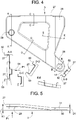
- a step roller 9 and an emergency guide hook 10 are arranged at the first cheek 3.
- a stepped roller 11 and an emergency guide hook 12 are arranged on the second cheek 5.
- the step roller 9,11 leads the level 1 along a track of the escalator.
- the emergency guide hook 10,12 is based on failure of the step roller 9,11 on an emergency guide the escalator and forces the level 1 back to the track.
- the stage 1 is connected by means of a stepped axis 13 with the step chain of the escalator.
- the stepped axis 13 is constructed in several parts.
- An axle journal 14 made of a round material is rotatably supported in a sleeve 15 of the center cheek 4 serving as a sliding bearing.
- On the first cheek 3 serving as a plain bearing bush 16 is arranged, wherein a first driving axle 17 is rotatably mounted at one end in the bushing 16 and the other end is connected by a bridge 18 with the journal 14 of the center cheek 4.
- a second driving axle 20 is rotatably mounted at one end in the sleeve 19 and the other end is connected by means of a bridge 21 with the journal 14 of the center cheek 4.
- the driving axles 17, 20 are produced away from the sheet metal coil by means of a roll forming method and cut to length depending on the step width.
- the stage 1 is thus supported at one end by the chain rollers and at the other end by the step rollers 9, 11.
- Fig. 2 shows the complete stage 1 seen from below, in which the step skeleton 2 has been supplemented with a tread element 22, a step edge 23 and a setting element 24.
- the tread element 22 and / or the setting element 24 may also consist of more than one part.
- the one-piece tread element 22 or the one-piece setting element 24 seen longitudinally in the direction of travel and / or be divided transversely thereto.
- the tread element 22 as well as the setting element 24 is produced in two steps. In a first step, the sheet removed from the sheet metal coil is directed and preformed or pre-corrugated by means of a toothed shaft to about 50% and then cut to length depending on the appearance.
- the preformed component is formed by means of deep drawing process to the final web / groove profile with webs and grooves.
- the tread element 22 as well as the setting element 24 can also be deep-drawn in one step, wherein 3 to 10 webs and grooves are deep-drawn, then the thermoforming sheet is pushed further, then again 3 to 10 webs and grooves deep-drawn and so on.
- a deep-drawn sheet for example, 0.25 to 1.25 mm thickness is deep drawn to 10 to 15 mm.
- the web / groove profile of the tread element 22 has on the carrier side on each second web a small tooth 25 which meshes with the web / groove profile of the positioning element 24 of the adjacent step. The gap between the steps is thereby projecting and springing back.
- the step edge 23 for example, made of ceramic or natural fiber or plastic by injection molding or aluminum die-cast method is placed on the bridge 7 and screwed from below with the bridge 7. Other materials such as natural fibers, synthetic fibers, GRP, CFRP or plastic or NIRO and colors such as yellow, red, black, blue or mixed colors are also possible.
- the step edge 23 is formed so that the tread element 22 as well as the setting element 24 can be inserted into the step edge 23.
- Fig. 3 shows a section in the direction of travel through the stage 1 at the location of the axle journal 14 on the second cheek 5 seen.
- the tread element 22 is screwless, for example, connected by means of spot welding with the support 6 and the bridge 7.
- the setting element 24 is pushed into the step edge 23 and screwless, for example, connected by means of spot welding with the console 8.
- NIRO stainless steel
- ALU aluminum
- synthetic fiber composites ceramics, copper, brass, titanium sheet and so forth are also conceivable for the tread element 22 and / or for the setting element 24.
- Fig. 4 shows a side view of the first cheek 3 seen from the outside or in the direction of the arrow designated P1.
- the sheet metal blank is held at the edge by means of hold downs and pressed the free surface of the thermoforming sheet by means of stamp in a die.
- Fig. 4 also shows sections along the lines AA, BB, CC, DD and EE.
- the broken line shows the parts of the thermoforming body removed after the thermoforming process by means of knives or lasers, in particular the edges 50 retained during the thermoforming process and the covers 51 of the cheeks 28, 29 for the step roller 9 and the Miter shaft 17.
- the cheek eye 28 for the step roller 9 is directed in the direction of the stiffener 27 or inwardly or deep drawn (section BB), the cheek eye 29 for the cam axis 17 is directed outwards (counter to the direction P1) or deep drawn ( Section AA).
- Fig. 5 shows a plan view of the first cheek 3.
- the first cheek 3 has for stiffening a slight crank K1 inward, wherein K1 may be 20 to 35 mm, for example.
- D1 is the thickness of the stiffener 27, wherein D1 is composed of the thickness of the deep-drawn sheet, the Umbugradius 30 and the deep-drawn wall 31.
- D1 may for example be 15-42 mm, wherein the thickness of the thermoforming sheet can be 1.1-2.2 mm and wherein the ratio of the sheet thickness of the cheek body 26,32 of the cheeks 3,4,5 to the height D1 of the stiffener 27,44 at least 1:10 is.
- a deep-drawn sheet has a weight of 14.4 kg / m 2 for a sheet thickness of 1.8 mm and a weight of 9.6 kg / m for a sheet thickness of 1.2 mm 2 .
- the second cheek 5 is constructed comparable to the one-piece first cheek 3.
- the center cheek 4 is also deep-drawn and constructed in addition to the crank K1 and the cheeks eyes comparable to the first cheek 3.
- the sheet thickness of the thermoforming sheet can be selected depending on the step width (the smaller the step width, the thinner the sheet metal) or it can be used for different step widths the same sheet thickness.
- Fig. 6 and Fig. 7 show the second cheek 5 with details of the attachment of the step roller 11 and the emergency guide hook 12 on the cheek body 32 with stiffener 44.
- the attachment of the step roller 9 and the emergency guide hook 10 on the first cheek 3 is identical.
- Another emergency guide hook can be arranged on the cheek body 26 and 32, respectively.
- a journal 33 is held by a bushing 35.1, which is pressed or clamped or screwed into the cheek eye 34, for example.
- the journal 33 has a journal 35 for supporting the roller bearing and at the other end a thread 36.
- One in a bore 37 of the journal Self-tapping screw 38 presses a washer 39 on an inner bearing ring 40 of the roller bearing.
- the cap 42 additionally strengthens the connection of the axle journal 33 with the cheek body 32 and stiffens the cheek body 32 at this location.
- a slot with fold 45 is provided which secures the emergency guide hook 12 against rotation when tightening the nut 41 and holds on the stiffener 44.
- the bridges 7 ', 7 "with the cheeks 3', 4 ', 4", 4'"and 5 ' form an equally stable skeleton as in the stage the components 6, 7 and 8 with the cheeks 3, 4 and 5 ,
- the bridges 7 ', 7 “have (as well as the components 6, 7 and 8 of the stage) over their entire length a constant cross section, so they can be produced endlessly by means of a roll forming process and can be cut to length depending on the pallet width.
- the bridges 7 'and 7 can be made identical, a bridge 7' can be brought into the mirror image position required for the bridge 7" simply by turning.
- the pallet rollers 9 'and 11' are analogous to the step rollers 9 and 11 attached.
- Emergency guide hooks are dispensable for pallets.
- the tread element 22 'of the pallet 1' has a small tooth 25 on the carrier side on every second web.
- exactly every intermediate bridge has such a small protruding tooth (in Fig. 8 not visible). The gap between two pallets 1 'is thus projecting and rebounding just as in the steps.
- Fig. 9 shows a palette from the side. It has already been mentioned that the cheeks (in Fig. 9 only the cheek 3 'is visible) with the bridges 7' and 7 "(in Fig. 9 not visible) screwless, for example by means of spot welding method, are connected. Likewise, the tread element 22 'without screws, for example by means of spot welding method, with the two bridges 7' and 7 "connected.
- Fig. 10 shows a cheek 3 'of a pallet in perspective view.
- This cheek is (analogous to the cheeks at the stage) produced by a deep-drawing process.
- a stiffener 27 'by a manufactured during deep drawing circumferential wall 31' is present, which merges with a Umbugradius 30 'in the cheek body 32'.
- the preparation of the cheek eyes 28 'and 29' is carried out quite analogously, as was explained in the stage.
- the bridge 7 ' has a recess 51 on its upper side, with which it bears against the tread element 22'.
- This support 52 supports the tread element 22 'at the two lateral edges where the tread element 22' projects beyond the bridges 7 'and 7 "(the bridges 7' and 7" terminate at the side cheeks 3 'and 5'.)
- this is Tread element supported over its entire width.
Description
Die Erfindung betrifft eine Stufe für eine Fahrtreppe oder eine Palette für einen Fahrsteig umfassend ein Stufenskelett oder Palettenskelett als Träger für mindestens ein Trittelement gemäß der Definition des unabhängigen Patentanspruchs.The invention relates to a step for an escalator or pallet for a moving walkway comprising a step skeleton or pallet skeleton as a support for at least one tread element according to the definition of the independent claim.
Aus der Patentschrift
Solch eine Stufe ist sehr schwer, weil das Tragblech - trotz zur Versteifung vorgesehener Sicken - relativ dick ausgeführt sein muss, wenn die erforderliche Stabilität sichergestellt werden soll.Such a step is very difficult because the support plate - despite provided for stiffening beads - must be made relatively thick, if the required stability is to be ensured.
Aus der
Die gattungsbildende
Hier will die Erfindung Abhilfe schaffen. Die Erfindung, wie sie in Anspruch 1 gekennzeichnet ist, löst die Aufgabe, eine aus Blech gefertigte, leichte Stufe oder Palette mit hoher Steifigkeit zu schaffen.The invention aims to remedy this situation. The invention, as characterized in
Vorteilhafte Weiterbildungen der Erfindung sind in den abhängigen Patentansprüchen angegeben.Advantageous developments of the invention are specified in the dependent claims.
Eine Stufe führt gegenüber den benachbarten Stufen in vertikaler Richtung eine Relativbewegung aus, insbesondere beim Übergang vorn geneigten Fahrtreppenabschnitt zum horizontalen Fahrtreppenabschnitt. Die Stufenstruktur der Fahrtreppe wird in eine Ebene bzw. Bandstruktur übergeführt. Die Relativbewegung wird durch einen entsprechenden Verlauf der Führungsbahnen für die Stufenrollen erzeugt. Außerdem hat die Stufe in Fahrtrichtung geschnitten etwa einen dreieckförmigen Querschnitt. Eine Palette führt gegenüber den benachbarten Paletten keine Relativbewegung in vertikaler Richtung aus. Der aus Paletten bestehende Fahrsteig ändert bei einer Richtungsänderung seine Oberflächenstruktur nicht, eine stufenlose Bandstruktur als Transportfläche ist immer vorhanden. Eine Palette ist vergleichbar mit einer Stufe aufgebaut und hat in Fahrtrichtung geschnitten etwa einen rechteckförmigen Querschnitt ohne sichtbares Setzelement. Eine Fahrtreppe weist mindestens eine erfindungsgemäße Stufe auf, wobei die übrigen Stufen beispielsweise herkömmliche Aluminiumstufen oder Blechstufen sind. Im weiteren Verlauf wird der besseren Lesbarkeit wegen lediglich eine mittels Tiefziehverfahren hergestellte Stufe beschrieben. Die Ausführungen gelten aber sinngemäß für eine mittels Tiefziehverfahren hergestellte Palette.One step performs a relative movement relative to the adjacent steps in the vertical direction, in particular in the transition from the front inclined escalator section to the horizontal escalator section. The step structure of the escalator is converted into a plane or band structure. The relative movement is generated by a corresponding course of the guideways for the step rollers. In addition, the step in the direction of travel has approximately a triangular cross-section. A pallet does not perform any relative movement in the vertical direction relative to the adjacent pallets. The moving pavement consisting of pallets does not change its surface structure when the direction changes, a stepless belt structure as transport surface is always available. A pallet is constructed comparable to a step and has cut in the direction of travel about a rectangular cross section without visible setting element. An escalator has at least one stage according to the invention, the remaining stages being, for example, conventional aluminum stages or sheet metal stages. In the further course, for the sake of better readability, only one stage produced by means of deep drawing is described. However, the statements apply mutatis mutandis to a range produced by deep drawing process.
Die durch die Erfindung erreichten Vorteile sind im Wesentlichen darin zu sehen, dass mit der skelettartigen Blechkonstruktion der Stufe Gewichtseinsparungen und Kosteneinsparungen machbar sind. Leichtere Stufen bedeuten auch eine kleinere Antriebsleistung für den Fahrtreppenantrieb. Die wesentlichen Bauteile der Stufen, wie beispielsweise Stufenwangen, Trittelement und Setzelement werden mittels eines Tiefziehverfahrens aus dünnem Tiefziehblech hergestellt. Trotz des dünnen Blechs genügt die erfindungsgemäße Stufe den Vorgaben und Belastungstests der europäischen Norm EN 115 sowie der amerikanischen Norm ASME A17.1, gemäß welchen die erfindungsgemäße Stufe einem statischen Test und einem dynamischen Test genügen muss. Beim statischen Test wird die Stufe mit einer senkrecht zum Trittelement wirkenden Kraft von 3000 N mittig belastet, wobei eine Auslenkung von höchstens 4 mm auftreten darf. Nach der Krafteinwirkung darf die Stufe keine bleibende Deformation aufweisen. Beim dynamischen Test wird die Stufe mit einer pulsierenden Kraft mittig belastet, wobei die Kraft zwischen 500 N und 3000 N variiert mit einer Frequenz zwischen 5 Hz und 20 Hz und mindestens 5x10⁶ Zyklen. Nach dem Test darf die Stufe eine bleibende Deformation von höchstens 4 mm aufweisen.The advantages achieved by the invention are essentially to be seen in the fact that weight savings and cost savings are feasible with the skeleton-type sheet metal construction of the stage. Lighter steps also mean smaller drive power for the escalator drive. The main components of the stages, such as For example, step cheeks, tread element and setting element are made by means of a deep-drawing process of thin deep-drawn sheet metal. Despite the thin sheet, the stage according to the invention meets the requirements and load tests of the European standard EN 115 and the American standard ASME A17.1, according to which the stage according to the invention must satisfy a static test and a dynamic test. In the static test, the step is centrally loaded with a force acting perpendicular to the tread element of 3000 N, with a deflection of at most 4 mm may occur. After the force has been applied, the step must not show any permanent deformation. In the dynamic test, the stage is centered with a pulsating force, with the force varying between 500 N and 3000 N, with a frequency between 5 Hz and 20 Hz and at least 5x10 6 cycles. After the test, the step may have a permanent deformation of not more than 4 mm.
Weiter vorteilhaft ist, dass die Bauteile ab einer mittels Abwickeleinrichtung gehaltenen und abwickelbaren Blechrolle von beispielsweise 2 m bis 4 m Durchmesser, im Weiteren Blechcoil genannt, fertigungsoptimiert hergestellt werden können. Mit Mehrfach-Abwickeleinrichtungen kann der Arbeitsfluss unterbruchsfrei gestaltet und die Fertigungszeit weiter reduziert werden.It is also advantageous that the components can be manufactured optimized production from a roll of paper held by unwinding and developable, for example, 2 m to 4 m in diameter, hereinafter referred to as sheet coil. With multiple unwinding devices, the workflow can be made interruption-free and production time can be further reduced.
Die erfindungsgemäße Stufe mit skelettartiger Blechkonstruktion ist leichter und wesentlich kostengünstiger als eine Druckgussstufe aus Aluminium, insbesondere bei steigendem Aluminiumpreis. Eine 600 mm breite Stufe wiegt etwa noch 8,6 kg, eine 800 mm breite Stufe wiegt etwa noch 10,8 kg und eine 1000 mm breite Stufe wiegt etwa noch 13,1 kg. Weiter vorteilhaft ist bei dieser Bauweise, dass die Stufenbreite oder auch der Umrüstvorgang bei geringen Stückzahlen keine aufwendigen Mehrarbeiten erfordert. Eine auf minimales Gewicht und maximale Belastung gemäß oben genannter EN 115 optimierte Stufe ist mit dünnen Tiefziehblechen von beispielsweise 1,1 bis 1,9 mm Dicke machbar, die mittels Tiefziehverfahren eine maximale Aussteifung der tragenden Bauteile ermöglichen. Präge- oder Biegeverfahren wären auch denkbar, die fertige Stufe wäre aber wesentlich schwerer, weil bei diesen Herstellungsverfahren größere Blechdicken (mindestens 4 mm Blechdicke) notwendig sind.The inventive step with skeletal sheet metal construction is lighter and much cheaper than a die-cast aluminum, especially with increasing aluminum price. A 600 mm wide stage weighs about 8.6 kg, a 800 mm wide stage weighs about 10.8 kg and a 1000 mm wide stage weighs about 13.1 kg. It is also advantageous in this construction that the step width or even the conversion process requires no complicated additional work in small quantities. An optimized to minimum weight and maximum load according to the above-mentioned EN 115 level is feasible with thin thermoforming sheets, for example, 1.1 to 1.9 mm thickness, which allow by means of deep drawing process, a maximum stiffening of the supporting components. Embossing or bending processes would also be conceivable but the finished stage would be much heavier, because in this manufacturing process larger sheet thicknesses (at least 4 mm sheet thickness) are necessary.
Wesentlich ist bei der vorliegenden Erfindung, dass das Stufenskelett oder Palettenskelett als Blechteile gefertigt sind, d.h. aus ebenen Elementen geformt sind. Dabei weisen die Wangen einen Wangenkörper und entlang der Ränder des Wangenkörpers eine umlaufende, wandartige Aussteifung auf. Durch diese Aussteifung wird trotz dünnen (und somit leichten) Blechs eine verblüffend hohe Stabilität erzielt. Solche Wangen können vorteilhaft durch ein Tiefziehverfahren hergestellt werden.It is essential in the present invention that the step skeleton or pallet skeleton are made as sheet metal parts, i. are formed from flat elements. The cheeks have a cheek body and along the edges of the cheek body on a circumferential, wall-like stiffening. This stiffening, despite thin (and thus light) sheet metal results in an amazingly high stability. Such cheeks can be advantageously prepared by a deep drawing process.
Beim Tiefziehverfahren drückt ein Stempel einen ebenen Blechzuschnitt in eine vorgefertigte Matrize, wobei der Rand des Blechzuschnittes mittels eines Niederhalters festgehalten wird. Bei der durch Stempel und Matrize bewirkten Kaltumformung des Tiefziehbleches erfolgt unterhalb des Niederhalters eine vorübergehende Plastifizierung und Kaltverfestigung des Tiefziehbleches. Aus dem zweidimensionalen, meist aus einem Blechband gestanzten Blechzuschnitt wird ein dreidimensionaler Körper geformt mit Boden und umlaufenden Wänden, wobei die Wandstärke etwas kleiner ist als die ursprüngliche Blechdicke. Der Boden kann in weiteren Verfahrensschritten, beispielsweise mittels hydraulischem Tiefen in den Stempel oder in die Matrize umgeformt werden. Im unten dargelegten Ausführungsbeispiel werden so die Wangenaugen gefertigt. Nach der Umformung wird der Rand von den Wänden durch Beschneiden beispielsweise mittels Messer oder Laser oder Stanze oder Wasserstrahl abgetrennt. Das Tiefziehblech muss eigens für die Umformung geschaffen sein. Im unten dargelegten Ausführungsbeispiel wird beispielsweise ein Tiefziehblech mit der Bezeichnung H380 oder H400 oder H900 oder H1100 verwendet. Diese Stahlsorten basieren im Wesentlichen auf der festigkeitssteigernden Wirkung von Mikrolegierungszusätzen wie beispielsweise Niob und/oder Titan und/oder Mangan. Die gegenüber Weichstählen hohen Streckgrenzen dieser Stahlsorten erlauben eine Kaltumformung mit geringer Verformungsbeanspruchung bis zu sehr anspruchsvollen und komplexen Bauteilausformungen. Die Stahlsorten sind auf die jeweiligen Umformbedingungen abgestimmt, damit auch bei geringen Blechdicken die Neigung zu verformungsbedingten Einschnürungen, Faltenbildungen, Reißern oder Formungenauigkeiten durch elastische Rückfederung minimal ist. Das Tiefziehverfahren zeichnet sich aus durch ein großes Verhältnis der Blechdicke zur Höhe der tiefgezogenen Wand sowie der damit verbundenen hohen Belastbarkeit, Formgenauigkeit und Stabilität.In the deep-drawing process, a stamp presses a flat sheet metal blank into a prefabricated die, wherein the edge of the sheet metal blank is held by means of a hold-down. In the cold forming of the deep-drawn sheet caused by punch and die, a temporary plasticization and work-hardening of the deep-drawn sheet occurs below the hold-down. From the two-dimensional, usually punched from a sheet metal sheet metal cutting a three-dimensional body is formed with bottom and peripheral walls, the wall thickness is slightly smaller than the original sheet thickness. The soil can be formed in further process steps, for example by means of hydraulic depths in the stamp or in the die. In the embodiment set out below, the cheeks eyes are made. After forming the edge of the walls is separated by trimming, for example by means of a knife or laser or punch or water jet. The deep-drawn sheet has to be specially created for the forming. In the embodiment set out below, for example, a deep-drawn sheet with the designation H380 or H400 or H900 or H1100 is used. These steel grades are based essentially on the strength-increasing effect of micro-alloying additives such as niobium and / or titanium and / or manganese. The yield strengths of these steels, which are high compared to mild steels, allow for cold forming with low deformation stress up to very demanding and complex component formations. The types of steel are tuned to the respective forming conditions, so that even with low sheet thicknesses the tendency to deformation-related constrictions, wrinkles, tearing or inaccurate shape by elastic springback is minimal. The deep drawing process is characterized by a large ratio of the sheet thickness to the height of the deep-drawn wall and the associated high load capacity, dimensional accuracy and stability.
Beim Rollumformverfahren, auch kontinuierliches Biegeverfahren genannt, wird ein Blechband ab Blechcoil mit Hilfe von mehreren hintereinander angeordneten Walzenpaaren bzw. Rollenpaaren durch Kaltumformung zu stark beanspruchbaren Profilen umgeformt.When Rollumformverfahren, also called continuous bending process, a sheet metal strip from sheet metal coil with the aid of several successively arranged pairs of rollers or pairs of rollers by cold forming to heavy-claimable profiles is formed.
Anhand der beiliegenden Figuren wird die vorliegende Erfindung näher erläutert. Es zeigen:
-
Fig. 1 ein Skelett der erfindungsgemäßen Stufe; -
Fig. 2 die erfindungsgemäße Stufe; -
Fig. 3 einen Schnitt durch die Stufe in Fahrtrichtung; -
Fig. 4 eine Seitenansicht einer Wange mit Schnitten A-A bis E-E; -
Fig. 5 eine Draufsicht der Wange; -
Fig. 6 eine Wange mit Stufenrolle und Notführungshaken; -
Fig. 7 Einzelheiten eines Rollenlagers; -
Fig. 8 eine erfindungsgemäße Palette in perspektivischer Ansicht von unten; -
Fig. 9 dieselbe in Seitenansicht; -
Fig. 10 eine Wange dieser Palette; -
Fig. 11 eine Brücke dieser Palette in Seitenansicht; und -
Fig. 12 eine Abstützung dieser Palette in perspektivischer Ansicht.
-
Fig. 1 a skeleton of the stage according to the invention; -
Fig. 2 the stage according to the invention; -
Fig. 3 a section through the step in the direction of travel; -
Fig. 4 a side view of a cheek with sections AA to EE; -
Fig. 5 a top view of the cheek; -
Fig. 6 a cheek with stepped roller and emergency guide hook; -
Fig. 7 Details of a roller bearing; -
Fig. 8 a pallet according to the invention in a perspective view from below; -
Fig. 9 the same in side view; -
Fig. 10 a cheek of this palette; -
Fig. 11 a bridge of this palette in side view; and -
Fig. 12 a support of this pallet in perspective view.
An der ersten Wange 3 sind eine Stufenrolle 9 und ein Notführungshaken 10 angeordnet. An der zweiten Wange 5 sind eine Stufenrolle 11 und ein Notführungshaken 12 angeordnet. Die Stufenrolle 9,11 führt die Stufe 1 entlang einer Laufbahn der Fahrtreppe. Der Notführungshaken 10,12 stützt sich bei Versagen der Stufenrolle 9,11 auf einer Notführung der Fahrtreppe ab und zwingt die Stufe 1 auf die Laufbahn zurück.At the
Die Stufe 1 ist mittels einer Stufenachse 13 mit der Stufenkette der Fahrtreppe verbunden. Die Stufenachse 13 ist mehrteilig aufgebaut. Ein aus einem Rundmaterial gefertigter Achszapfen 14 ist drehbar in einer als Gleitlager dienenden Buchse 15 der Mittenwange 4 gelagert. An der ersten Wange 3 ist eine als Gleitlager dienende Buchse 16 angeordnet, wobei eine erste Mitnehmerachse 17 einenends in der Buchse 16 drehbar gelagert ist und anderenends mittels einer Bride 18 mit dem Achszapfen 14 der Mittenwange 4 verbunden ist. An der zweiten Wange 5 ist eine als Gleitlager dienende Buchse 19 angeordnet, wobei eine zweite Mitnehmerachse 20 einenends in der Buchse 19 drehbar gelagert ist und anderenends mittels einer Bride 21 mit dem Achszapfen 14 der Mittenwange 4 verbunden ist.The
Die Mitnehmerachsen 17,20 werden vom Blechcoil weg mittels eines Rollumformverfahrens hergestellt und je nach Stufenbreite abgelängt. Bei gelöster Bride 18,21 wird je Seite der Stufe 1 die Mitnehmerachse 17,20 über einen Kettenbolzen der Stufenkette geschoben und die Bride 18,21 wieder festgezogen, womit die Stufe 1 mit der die Stufe 1 bewegenden Stufenkette verbunden ist.The driving
Die Stufenachse 13 bildet zusammen mit den Kettenbolzen eine durchgehende Achse von einer Kettenrolle zur gegenüberliegenden Kettenrolle. Die Stufe 1 wird somit einenends von den Kettenrollen und anderenends von den Stufenrollen 9,11 getragen.The stepped
Die beispielsweise aus Keramik oder Naturfaser oder Kunststoff im Spritzgießverfahren oder aus Aluminium im Druckgussverfahren gefertigte Stufenkante 23 wird auf die Brücke 7 aufgesetzt und von unten mit der Brücke 7 verschraubt. Andere Materialien wie Naturfaserstoffe, Kunstfaserstoffe, GFK, CFK oder Kunststoff oder NIRO und Farben wie gelb, rot, schwarz, blau oder Mischfarben sind auch möglich. Die Stufenkante 23 ist so ausgebildet, dass das Trittelement 22 wie auch das Setzelement 24 in die Stufenkante 23 eingeschoben werden kann.The
Je nach Kundenwunsch sind beispielsweise für das Trittelement 22 und/oder für das Setzelement 24 auch NIRO (rostfreier Stahl), ALU (Aluminium), Kunstfaserkomposite, Keramik, Kupfer, Messing, Titanblech und so weiter denkbar.Depending on the customer, for example, NIRO (stainless steel), ALU (aluminum), synthetic fiber composites, ceramics, copper, brass, titanium sheet and so forth are also conceivable for the
Anhand der
Da Fahrsteige meist breiter als Fahrtreppen sind, sind bei einer Palette 1' mehrere Mittenwangen notwendig: beim dargestellten Beispiel gibt es drei Mittenwangen 4', 4" und 4"'. Zusammen mit den beiden Seitenwangen 3' und 5' sind das insgesamt fünf Wangen. Da Paletten vorne/hinten weitgehend symmetrisch sind, sind zwei Träger 7' und 7" vorgesehen, die identisch sind (statt Träger 7 und Brücke 6 bei der Stufe 1), um das Trittelement 22' zu lagern. Die Träger 7', 7" sind mit den Wangen 3', 4', 4", 4'" und 5' schraubenlos verbunden, beispielsweise mittels Punktschweißverfahren. Da Paletten kein Setzelement aufweisen, sind auch die Stufenkante 23 und die Konsole 8 entbehrlich. Damit die Wangen 3', 4', 4", 4'" und 5' auch an ihrer unteren Seite (der dem Trittelement 22' abgewandten Seite) stabilisiert werden, sind die Brücken 7', 7" so ausgebildet, dass sie der Form der Wangen 3', 4', 4", 4'" und 5' weitgehend folgen (vgl. die
Auch die Brücken 7', 7" haben (ebenso wie die Bauteile 6, 7 und 8 der Stufe) über ihre gesamte Länge einen konstanten Querschnitt, sodass sie mittels eines Rollumformverfahrens endlos hergestellt und je nach Palettenbreite abgelängt werden können. Hier ist ein besonderer Vorteil, dass die Brücken 7' und 7" identisch hergestellt werden können; eine Brücke 7' kann in die für die Brücke 7" erforderliche spiegelbildliche Lage einfach durch Umdrehen gebracht werden.Also, the
Die Palettenrollen 9' und 11' sind analog wie die Stufenrollen 9 und 11 befestigt. Notführungshaken sind bei Paletten entbehrlich.The pallet rollers 9 'and 11' are analogous to the
Unterschiedlich ist allerdings die Palettenachse 13', die im Gegensatz zur Stufenachse 13 nicht durchgeht, sondern zweigeteilt ist. Dies ist deshalb möglich, weil mehrere Mittenwangen 4', 4" und 4'" vorgesehen sind. Es gibt daher zwei Achszapfen 14', 14", die in den Mittenwangen 4'" bzw. 4" gelagert sind. Die Lagerung der Mitnehmerachsen 17' und 20' in den Seitenwangen 3' und 5' sowie die Verbindung mittels Briden 18' und 21' ist analog wie bei der Stufe 1.However, different is the pallet axis 13 ', which in contrast to the
Auch das Trittelement 22' der Palette 1' weist trägerseitig an jedem zweiten Steg einen kleinen Zahn 25 auf. Rollenseitig weist genau jeder dazwischen liegende Steg solch einen kleinen vorspringenden Zahn auf (in
Die Brücke 7' weist an ihrer oberen Seite, mit der sie am Trittelement 22' anliegt, eine Vertiefung 51 auf. Analoges gilt natürlich für die Brücke 7". Damit ergeben sich zwischen den beiden Brücken 7' und 7" einerseits und dem Trittelement 22' Schlitze, in welche eine Abstützung 52 mit Laschen 53 eingeschoben werden kann. Diese Abstützung 52 unterstützt das Trittelement 22' an den beiden seitlichen Rändern, wo das Trittelement 22' die Brücken 7' und 7" überragt. (Die Brücken 7' und 7" enden bei den Seitenwangen 3' und 5'.) Damit ist das Trittelement über seine ganze Breite unterstützt.The bridge 7 'has a
Claims (11)
- Step (1) for an escalator or plate (1') for a moving walkway, comprising a step skeleton (2) or plate skeleton as support for at least one tread element (22, 22'), wherein the step skeleton (2) or plate skeleton comprises, as load-bearing components, side cheeks (3, 5; 3', 5') and at least one centre cheek (4; 4', 4", 4'"), which extend in the travel direction of the step (1) or plate (1') and which are connected by means of components (6, 7, 8; 7', 7") extending transversely to the travel direction, whereby when the step (1) or plate (1') is loaded the force is distributed to all cheeks (3, 4, 5; 3', 4', 4", 4"', 5'), wherein the step skeleton (2) or plate skeleton is constructed as sheet metal parts, characterised in that, as load-bearing components, side cheeks (3, 5; 3', 5') and at least one centre cheek (4; 4', 4", 4'") are produced by means of a deep-drawing method, that the cheeks (3, 4, 5; 3', 4', 4", 4'", 5') comprise a cheek body (26, 32; 26') and a wall-like stiffening (27, 44; 27') along the edges of the cheek body (26, 32; 26'), that the cheeks (3, 4, 5; 3', 4', 4", 4"', 5') have cheek eyes (28, 29, 34; 28', 29') in the form of passages which are surrounded by protruding edges and which serve for the fastening of axles (13, 33; 13', 13"), and that a respective step roller (9, 11) or plate roller (9', 11') is provided for each side cheek (3, 5; 3', 5'), wherein an axle pin (33) supporting the step roller (9, 11) or plate roller (9', 11') is arranged at a cheek eye (28, 34; 28') and a cap (42) is provided which additionally strengthens the connection of the axle pin (33) with the cheek body (26, 32; 26') and stiffens the cheek body (26, 32; 26') at the location.
- Step according to claim 1, characterised in that the step skeleton (2) additionally serves as a support for at least one riser element (24).
- Step or plate according to one of the preceding claims, characterised in that the ratio of the sheet metal thickness of the cheek body (26, 32; 26') of the cheeks (3, 4, 5; 3', 4', 4", 4'", 5') to the height (D1) of the stiffening (27, 44; 27') is at least 1:10.
- Step or plate according to any one of the preceding claims, characterised in that a step axle (13) or plate axle (13', 13") is provided, which penetrates the cheeks (3, 4, 5; 3', 4", 4'", 5') and has for each step side or plate side a respective entrainer axle (17, 20; 17', 20') pushable onto a chain pin of a chain roller of the step chain or plate chain.
- Step according to any one of claims 1 to 4, characterised in that the components connecting the cheeks (3, 4, 5) are a carrier (6), a bridge (7) and a bracket (8), which are connected with the cheeks (3, 4, 5) without screws and connected with the tread element (22) and the riser element (24) without screws or connected by welding.
- Step according to claim 5, characterised in that a step edge (23) into which the tread element (22) and/or the riser element (24) is or are insertable is arranged at the bridge (7).
- Plate according to any one of claims 1, 3 and 4, characterised in that the components connecting the cheeks (3', 4', 4", 4''', 5') are two bridges (7', 7") which are connected with the cheeks (3', 4', 4", 4''', 5') without screws and are connected with the tread element (22) without screws or connected by welding.
- Step or plate according to any one of the preceding claims, characterised in that the step (1) or plate (1') has a weight of approximately 8.6 kilograms for a step width or plate width of 600 millimetres, a weight of approximately 10.8 kilograms for a step width or plate width of 800 millimetres or a weight of approximately 13.1 kilograms for a step width or plate width of 1000 millimetres.
- Method of producing a step (1) or plate (1') according to any one of claims 1 to 8, comprising a step skeleton (2) or plate skeleton made of sheet metal parts, characterised in that, as load-bearing components, side cheeks (3, 5; 3', 5') and at least one centre cheek (4; 4', 4", 4'") are produced by means of a deep-drawing method in which a cheek (3, 4, 5; 3', 4', 4", 4"', 5') is formed from a two-dimensional sheet metal blank as a three-dimensional body with base or cheek body (26, 32; 26') and stiffenings (27; 27') or walls (31; 31') and after the re-shaping the edge is separated from the walls (31; 31') by trimming, that the base is re-shaped to form cheek eyes (28, 29, 34'; 28', 29') in further deep-drawing steps and that a respective step roller (9, 11) or plate roller (9', 11') is provided for each side cheek (3, 5; 3', 5'), wherein an axle pin (33) supporting the step roller (9, 11) or plate roller (9', 11') is arranged at a cheek eye (28, 34; 28') and a cap (42) is provided which additionally strengthens the connection of the axle pin (33) with the cheek body (26, 32; 26') and stiffens the cheek body (26, 32; 26') at its location.
- Escalator with at least one step according to any one of claims 1 to 6 or 8.
- Moving walkway with at least one plate according to any one of claims 1, 3, 4, 7 and 8.
Priority Applications (2)
| Application Number | Priority Date | Filing Date | Title |
|---|---|---|---|
| EP08838320.3A EP2205516B1 (en) | 2007-10-01 | 2008-09-26 | Step for a moving staircase or pallet for and moving staircase with such a step or conveyor with such a pallet and method for manufacturing such a step or pallet |
| PL08838320T PL2205516T3 (en) | 2007-10-01 | 2008-09-26 | Step for a moving staircase or pallet for and moving staircase with such a step or conveyor with such a pallet and method for manufacturing such a step or pallet |
Applications Claiming Priority (3)
| Application Number | Priority Date | Filing Date | Title |
|---|---|---|---|
| EP07117647 | 2007-10-01 | ||
| EP08838320.3A EP2205516B1 (en) | 2007-10-01 | 2008-09-26 | Step for a moving staircase or pallet for and moving staircase with such a step or conveyor with such a pallet and method for manufacturing such a step or pallet |
| PCT/EP2008/062963 WO2009047142A1 (en) | 2007-10-01 | 2008-09-26 | Step for escalator or plate for travelator, and escalator or travelator and method for production |
Publications (2)
| Publication Number | Publication Date |
|---|---|
| EP2205516A1 EP2205516A1 (en) | 2010-07-14 |
| EP2205516B1 true EP2205516B1 (en) | 2017-01-18 |
Family
ID=38826419
Family Applications (1)
| Application Number | Title | Priority Date | Filing Date |
|---|---|---|---|
| EP08838320.3A Active EP2205516B1 (en) | 2007-10-01 | 2008-09-26 | Step for a moving staircase or pallet for and moving staircase with such a step or conveyor with such a pallet and method for manufacturing such a step or pallet |
Country Status (17)
| Country | Link |
|---|---|
| US (1) | US8469176B2 (en) |
| EP (1) | EP2205516B1 (en) |
| JP (1) | JP5492088B2 (en) |
| KR (1) | KR101591111B1 (en) |
| CN (1) | CN101808928B (en) |
| AU (1) | AU2008309740B2 (en) |
| BR (1) | BRPI0817926B1 (en) |
| CA (1) | CA2698941C (en) |
| ES (1) | ES2622445T3 (en) |
| HK (1) | HK1146539A1 (en) |
| MX (1) | MX2010003282A (en) |
| NZ (1) | NZ583852A (en) |
| PL (1) | PL2205516T3 (en) |
| RU (1) | RU2489342C2 (en) |
| UA (1) | UA99925C2 (en) |
| WO (1) | WO2009047142A1 (en) |
| ZA (1) | ZA201002843B (en) |
Families Citing this family (10)
| Publication number | Priority date | Publication date | Assignee | Title |
|---|---|---|---|---|
| DE102009033819B4 (en) * | 2009-07-18 | 2013-01-17 | Kone Corp. | Device for connecting a chain to a step or a pallet of a passenger conveyor |
| CN102530698A (en) * | 2012-02-21 | 2012-07-04 | 苏州新达电扶梯部件有限公司 | Support structure suitable for ultra-wide step of moving pavement |
| WO2018041929A1 (en) * | 2016-08-31 | 2018-03-08 | Inventio Ag | Escalator step constructed of plug-in parts |
| WO2019048306A1 (en) * | 2017-09-11 | 2019-03-14 | Inventio Ag | Step unit for a passenger transport installation and method for manufacturing a step unit |
| WO2020011597A1 (en) * | 2018-07-10 | 2020-01-16 | Thyssenkrupp Elevator Ag | Trailing-roller hollow shaft, trailing-roller mounting kit, escalator step comprising a trailing-roller hollow shaft, and method for mounting a trailing roller using a trailing-roller mounting kit |
| CN109132825B (en) * | 2018-11-01 | 2024-03-15 | 江苏飞亚金属制品有限公司 | Elevator step transmission shaft fixing device |
| CN109775546A (en) * | 2019-03-05 | 2019-05-21 | 杭州西奥电梯有限公司 | A kind of step of escalator |
| EP3747821A1 (en) * | 2019-06-04 | 2020-12-09 | Otis Elevator Company | Belt-driven people conveyors |
| DE102021130617A1 (en) | 2021-11-23 | 2023-05-25 | Tk Elevator Innovation And Operations Gmbh | Hollow axle and hollow axle set for arranging a tread element of a passenger conveyor belt on a drive chain |
| CN117443945B (en) * | 2023-12-26 | 2024-03-19 | 阳泉市广凯机械制造有限公司 | Manufacturing method of hot rolled thin cast steel strip |
Family Cites Families (22)
| Publication number | Priority date | Publication date | Assignee | Title |
|---|---|---|---|---|
| DD69443A (en) * | ||||
| JPS4727349Y1 (en) * | 1967-04-14 | 1972-08-21 | ||
| JPS499917Y1 (en) * | 1969-07-11 | 1974-03-08 | ||
| FR2152615B1 (en) * | 1971-09-07 | 1976-08-13 | Merkur Gmbh Metallwerk | |
| JPS5016282A (en) * | 1973-06-20 | 1975-02-20 | ||
| JPS5918315B2 (en) | 1978-06-05 | 1984-04-26 | 株式会社日立製作所 | man conveyor steps |
| JPS57180579A (en) * | 1981-04-30 | 1982-11-06 | Hitachi Ltd | Step for man conveyor |
| JPS58172181A (en) * | 1982-04-02 | 1983-10-08 | 株式会社日立製作所 | Man conveyor |
| JPH0635314B2 (en) * | 1985-03-01 | 1994-05-11 | 株式会社日立製作所 | Man conveyor tread |
| SU1282933A1 (en) * | 1985-05-12 | 1987-01-15 | Украинский научно-исследовательский институт металлов | Section-bending unit |
| DE3679364D1 (en) * | 1985-09-14 | 1991-06-27 | Eugen Rapp | METHOD AND DEVICE FOR CONNECTING THIN PLATES. |
| JPH0616906B2 (en) | 1986-05-16 | 1994-03-09 | 株式会社日立製作所 | Wave mountain plate forming equipment |
| US4984673A (en) * | 1988-03-07 | 1991-01-15 | Hitachi, Ltd. | Step of passenger conveyor method of manufacturing same, and wavy metal plate |
| NZ238537A (en) * | 1991-06-13 | 1994-05-26 | Escalator Advertising Ltd | Escalator step with advertising sign |
| EP0816278B1 (en) * | 1996-05-30 | 2004-02-04 | Inventio Ag | Escalator tread |
| JP2001310889A (en) | 2000-04-28 | 2001-11-06 | Hitachi Building Systems Co Ltd | Footstep for passenger conveyor |
| JP2004292106A (en) * | 2003-03-27 | 2004-10-21 | Hitachi Ltd | Passenger conveyor |
| RU2237101C1 (en) * | 2003-06-05 | 2004-09-27 | Открытое акционерное общество "Северсталь" | Steel for deep drawing and article made from the same (variants) |
| CN2721593Y (en) * | 2004-08-18 | 2005-08-31 | 袁华山 | Step of automatic moving staircase |
| JP2006131379A (en) * | 2004-11-08 | 2006-05-25 | Takenaka Komuten Co Ltd | Man conveyor and footstep |
| JP2007238328A (en) * | 2006-03-03 | 2007-09-20 | Inventio Ag | Escalator with novel emergency guide means |
| CN2880770Y (en) * | 2006-03-17 | 2007-03-21 | 袁华山 | Width safety, step of escalator |
-
2008
- 2008-09-26 KR KR1020107007007A patent/KR101591111B1/en active IP Right Grant
- 2008-09-26 MX MX2010003282A patent/MX2010003282A/en active IP Right Grant
- 2008-09-26 BR BRPI0817926-3A patent/BRPI0817926B1/en active IP Right Grant
- 2008-09-26 RU RU2010117201/11A patent/RU2489342C2/en active
- 2008-09-26 PL PL08838320T patent/PL2205516T3/en unknown
- 2008-09-26 WO PCT/EP2008/062963 patent/WO2009047142A1/en active Application Filing
- 2008-09-26 ES ES08838320.3T patent/ES2622445T3/en active Active
- 2008-09-26 EP EP08838320.3A patent/EP2205516B1/en active Active
- 2008-09-26 AU AU2008309740A patent/AU2008309740B2/en not_active Ceased
- 2008-09-26 CA CA2698941A patent/CA2698941C/en not_active Expired - Fee Related
- 2008-09-26 UA UAA201003736A patent/UA99925C2/en unknown
- 2008-09-26 US US12/680,787 patent/US8469176B2/en active Active
- 2008-09-26 JP JP2010527418A patent/JP5492088B2/en active Active
- 2008-09-26 NZ NZ583852A patent/NZ583852A/en unknown
- 2008-09-26 CN CN2008801095745A patent/CN101808928B/en active Active
-
2010
- 2010-04-22 ZA ZA2010/02843A patent/ZA201002843B/en unknown
-
2011
- 2011-01-13 HK HK11100313.7A patent/HK1146539A1/en unknown
Non-Patent Citations (1)
| Title |
|---|
| None * |
Also Published As
| Publication number | Publication date |
|---|---|
| JP5492088B2 (en) | 2014-05-14 |
| AU2008309740A1 (en) | 2009-04-16 |
| ES2622445T3 (en) | 2017-07-06 |
| CN101808928B (en) | 2013-09-18 |
| WO2009047142A1 (en) | 2009-04-16 |
| AU2008309740B2 (en) | 2014-04-10 |
| RU2489342C2 (en) | 2013-08-10 |
| US8469176B2 (en) | 2013-06-25 |
| MX2010003282A (en) | 2010-04-09 |
| ZA201002843B (en) | 2011-07-27 |
| EP2205516A1 (en) | 2010-07-14 |
| CN101808928A (en) | 2010-08-18 |
| KR101591111B1 (en) | 2016-02-02 |
| BRPI0817926B1 (en) | 2019-11-05 |
| WO2009047142A8 (en) | 2009-05-22 |
| UA99925C2 (en) | 2012-10-25 |
| JP2010540377A (en) | 2010-12-24 |
| RU2010117201A (en) | 2011-11-10 |
| CA2698941C (en) | 2016-04-05 |
| KR20100063102A (en) | 2010-06-10 |
| PL2205516T3 (en) | 2017-07-31 |
| CA2698941A1 (en) | 2009-04-16 |
| NZ583852A (en) | 2012-12-21 |
| BRPI0817926A2 (en) | 2015-04-07 |
| US20100206692A1 (en) | 2010-08-19 |
| HK1146539A1 (en) | 2011-06-17 |
Similar Documents
| Publication | Publication Date | Title |
|---|---|---|
| EP2205516B1 (en) | Step for a moving staircase or pallet for and moving staircase with such a step or conveyor with such a pallet and method for manufacturing such a step or pallet | |
| EP2144802B1 (en) | Kit for a body-shell structure | |
| EP2200923B1 (en) | Step for a moving staircase or pallet for and moving staircase with such a step | |
| EP3044153B1 (en) | Pallet for a moving walkway or step for an escalator | |
| EP2200925A1 (en) | Step support or plate support for tread units of a conveying device, tread units and conveying device | |
| EP1737778A2 (en) | Escalator or moving sidewalk | |
| DE2403374B2 (en) | PLASTIC PALLET | |
| EP1321424B1 (en) | Truss for escalator | |
| EP3931142B1 (en) | Framework section connection area | |
| DE202004012141U1 (en) | Plate for furniture, floors and similar items comprises at least one stiffening element which is located under the cover layers and consists of a light-weight building material | |
| WO2016083151A1 (en) | Support structure for a conveyor device | |
| DE19905650C1 (en) | Carrier beam for a freight truck floor is of plywood with vertical glue layers shrouded by a U-shaped metal reinforcement bar to be assembled into a floor carrier beam module | |
| EP0404019B1 (en) | Composed plastic pallet | |
| EP3181505A1 (en) | Step formed as one-piece light metal die casting | |
| WO2009047143A1 (en) | Step for escalator or plate for travelator, and escalator or travelator and method for production | |
| DE19632725A1 (en) | Platform, in particular tail lift for vehicles | |
| DE3200741C2 (en) | Loading pallet | |
| WO1996014971A1 (en) | Process for producing coated panel units | |
| EP3224187B1 (en) | Support frame for a transport device | |
| DE10133591B4 (en) | Floor platform with grooved rail and grooved rail for installation in a floor platform | |
| DE19800375C1 (en) | Ground mounting for wooden paving panels | |
| DE3328745A1 (en) | Roller path | |
| DE1131524B (en) | Cranked, profiled longitudinal member for vehicle frame | |
| EP1383972B1 (en) | Formwork support | |
| DE10236115B4 (en) | Step system for an escalator |
Legal Events
| Date | Code | Title | Description |
|---|---|---|---|
| PUAI | Public reference made under article 153(3) epc to a published international application that has entered the european phase |
Free format text: ORIGINAL CODE: 0009012 |
|
| 17P | Request for examination filed |
Effective date: 20100421 |
|
| AK | Designated contracting states |
Kind code of ref document: A1 Designated state(s): AT BE BG CH CY CZ DE DK EE ES FI FR GB GR HR HU IE IS IT LI LT LU LV MC MT NL NO PL PT RO SE SI SK TR |
|
| AX | Request for extension of the european patent |
Extension state: AL BA MK RS |
|
| DAX | Request for extension of the european patent (deleted) | ||
| REG | Reference to a national code |
Ref country code: HK Ref legal event code: DE Ref document number: 1146539 Country of ref document: HK |
|
| 17Q | First examination report despatched |
Effective date: 20151124 |
|
| GRAP | Despatch of communication of intention to grant a patent |
Free format text: ORIGINAL CODE: EPIDOSNIGR1 |
|
| RIN1 | Information on inventor provided before grant (corrected) |
Inventor name: KLEEWEIN, GERHARD Inventor name: MATHEISL, MICHAEL Inventor name: ILLEDITS, THOMAS Inventor name: NOVACEK, THOMAS |
|
| INTG | Intention to grant announced |
Effective date: 20160825 |
|
| GRAS | Grant fee paid |
Free format text: ORIGINAL CODE: EPIDOSNIGR3 |
|
| GRAA | (expected) grant |
Free format text: ORIGINAL CODE: 0009210 |
|
| AK | Designated contracting states |
Kind code of ref document: B1 Designated state(s): AT BE BG CH CY CZ DE DK EE ES FI FR GB GR HR HU IE IS IT LI LT LU LV MC MT NL NO PL PT RO SE SI SK TR |
|
| REG | Reference to a national code |
Ref country code: GB Ref legal event code: FG4D Free format text: NOT ENGLISH |
|
| REG | Reference to a national code |
Ref country code: CH Ref legal event code: EP |
|
| REG | Reference to a national code |
Ref country code: AT Ref legal event code: REF Ref document number: 862762 Country of ref document: AT Kind code of ref document: T Effective date: 20170215 |
|
| REG | Reference to a national code |
Ref country code: IE Ref legal event code: FG4D Free format text: LANGUAGE OF EP DOCUMENT: GERMAN |
|
| REG | Reference to a national code |
Ref country code: DE Ref legal event code: R096 Ref document number: 502008014979 Country of ref document: DE |
|
| REG | Reference to a national code |
Ref country code: NL Ref legal event code: MP Effective date: 20170118 |
|
| REG | Reference to a national code |
Ref country code: LT Ref legal event code: MG4D |
|
| PG25 | Lapsed in a contracting state [announced via postgrant information from national office to epo] |
Ref country code: NL Free format text: LAPSE BECAUSE OF FAILURE TO SUBMIT A TRANSLATION OF THE DESCRIPTION OR TO PAY THE FEE WITHIN THE PRESCRIBED TIME-LIMIT Effective date: 20170118 |
|
| REG | Reference to a national code |
Ref country code: ES Ref legal event code: FG2A Ref document number: 2622445 Country of ref document: ES Kind code of ref document: T3 Effective date: 20170706 |
|
| PG25 | Lapsed in a contracting state [announced via postgrant information from national office to epo] |
Ref country code: NO Free format text: LAPSE BECAUSE OF FAILURE TO SUBMIT A TRANSLATION OF THE DESCRIPTION OR TO PAY THE FEE WITHIN THE PRESCRIBED TIME-LIMIT Effective date: 20170418 Ref country code: GR Free format text: LAPSE BECAUSE OF FAILURE TO SUBMIT A TRANSLATION OF THE DESCRIPTION OR TO PAY THE FEE WITHIN THE PRESCRIBED TIME-LIMIT Effective date: 20170419 Ref country code: FI Free format text: LAPSE BECAUSE OF FAILURE TO SUBMIT A TRANSLATION OF THE DESCRIPTION OR TO PAY THE FEE WITHIN THE PRESCRIBED TIME-LIMIT Effective date: 20170118 Ref country code: LT Free format text: LAPSE BECAUSE OF FAILURE TO SUBMIT A TRANSLATION OF THE DESCRIPTION OR TO PAY THE FEE WITHIN THE PRESCRIBED TIME-LIMIT Effective date: 20170118 Ref country code: HR Free format text: LAPSE BECAUSE OF FAILURE TO SUBMIT A TRANSLATION OF THE DESCRIPTION OR TO PAY THE FEE WITHIN THE PRESCRIBED TIME-LIMIT Effective date: 20170118 Ref country code: IS Free format text: LAPSE BECAUSE OF FAILURE TO SUBMIT A TRANSLATION OF THE DESCRIPTION OR TO PAY THE FEE WITHIN THE PRESCRIBED TIME-LIMIT Effective date: 20170518 |
|
| PG25 | Lapsed in a contracting state [announced via postgrant information from national office to epo] |
Ref country code: PT Free format text: LAPSE BECAUSE OF FAILURE TO SUBMIT A TRANSLATION OF THE DESCRIPTION OR TO PAY THE FEE WITHIN THE PRESCRIBED TIME-LIMIT Effective date: 20170518 Ref country code: SE Free format text: LAPSE BECAUSE OF FAILURE TO SUBMIT A TRANSLATION OF THE DESCRIPTION OR TO PAY THE FEE WITHIN THE PRESCRIBED TIME-LIMIT Effective date: 20170118 Ref country code: LV Free format text: LAPSE BECAUSE OF FAILURE TO SUBMIT A TRANSLATION OF THE DESCRIPTION OR TO PAY THE FEE WITHIN THE PRESCRIBED TIME-LIMIT Effective date: 20170118 Ref country code: BG Free format text: LAPSE BECAUSE OF FAILURE TO SUBMIT A TRANSLATION OF THE DESCRIPTION OR TO PAY THE FEE WITHIN THE PRESCRIBED TIME-LIMIT Effective date: 20170418 |
|
| REG | Reference to a national code |
Ref country code: FR Ref legal event code: PLFP Year of fee payment: 10 |
|
| REG | Reference to a national code |
Ref country code: DE Ref legal event code: R097 Ref document number: 502008014979 Country of ref document: DE |
|
| PG25 | Lapsed in a contracting state [announced via postgrant information from national office to epo] |
Ref country code: RO Free format text: LAPSE BECAUSE OF FAILURE TO SUBMIT A TRANSLATION OF THE DESCRIPTION OR TO PAY THE FEE WITHIN THE PRESCRIBED TIME-LIMIT Effective date: 20170118 Ref country code: CZ Free format text: LAPSE BECAUSE OF FAILURE TO SUBMIT A TRANSLATION OF THE DESCRIPTION OR TO PAY THE FEE WITHIN THE PRESCRIBED TIME-LIMIT Effective date: 20170118 Ref country code: EE Free format text: LAPSE BECAUSE OF FAILURE TO SUBMIT A TRANSLATION OF THE DESCRIPTION OR TO PAY THE FEE WITHIN THE PRESCRIBED TIME-LIMIT Effective date: 20170118 Ref country code: SK Free format text: LAPSE BECAUSE OF FAILURE TO SUBMIT A TRANSLATION OF THE DESCRIPTION OR TO PAY THE FEE WITHIN THE PRESCRIBED TIME-LIMIT Effective date: 20170118 |
|
| PLBE | No opposition filed within time limit |
Free format text: ORIGINAL CODE: 0009261 |
|
| STAA | Information on the status of an ep patent application or granted ep patent |
Free format text: STATUS: NO OPPOSITION FILED WITHIN TIME LIMIT |
|
| PG25 | Lapsed in a contracting state [announced via postgrant information from national office to epo] |
Ref country code: DK Free format text: LAPSE BECAUSE OF FAILURE TO SUBMIT A TRANSLATION OF THE DESCRIPTION OR TO PAY THE FEE WITHIN THE PRESCRIBED TIME-LIMIT Effective date: 20170118 |
|
| REG | Reference to a national code |
Ref country code: HK Ref legal event code: GR Ref document number: 1146539 Country of ref document: HK |
|
| 26N | No opposition filed |
Effective date: 20171019 |
|
| PG25 | Lapsed in a contracting state [announced via postgrant information from national office to epo] |
Ref country code: SI Free format text: LAPSE BECAUSE OF FAILURE TO SUBMIT A TRANSLATION OF THE DESCRIPTION OR TO PAY THE FEE WITHIN THE PRESCRIBED TIME-LIMIT Effective date: 20170118 |
|
| REG | Reference to a national code |
Ref country code: CH Ref legal event code: PL |
|
| PG25 | Lapsed in a contracting state [announced via postgrant information from national office to epo] |
Ref country code: MC Free format text: LAPSE BECAUSE OF FAILURE TO SUBMIT A TRANSLATION OF THE DESCRIPTION OR TO PAY THE FEE WITHIN THE PRESCRIBED TIME-LIMIT Effective date: 20170118 |
|
| REG | Reference to a national code |
Ref country code: IE Ref legal event code: MM4A |
|
| REG | Reference to a national code |
Ref country code: BE Ref legal event code: MM Effective date: 20170930 |
|
| PG25 | Lapsed in a contracting state [announced via postgrant information from national office to epo] |
Ref country code: LU Free format text: LAPSE BECAUSE OF NON-PAYMENT OF DUE FEES Effective date: 20170926 |
|
| PG25 | Lapsed in a contracting state [announced via postgrant information from national office to epo] |
Ref country code: CH Free format text: LAPSE BECAUSE OF NON-PAYMENT OF DUE FEES Effective date: 20170930 Ref country code: LI Free format text: LAPSE BECAUSE OF NON-PAYMENT OF DUE FEES Effective date: 20170930 Ref country code: IE Free format text: LAPSE BECAUSE OF NON-PAYMENT OF DUE FEES Effective date: 20170926 |
|
| PG25 | Lapsed in a contracting state [announced via postgrant information from national office to epo] |
Ref country code: BE Free format text: LAPSE BECAUSE OF NON-PAYMENT OF DUE FEES Effective date: 20170930 |
|
| REG | Reference to a national code |
Ref country code: FR Ref legal event code: PLFP Year of fee payment: 11 |
|
| PG25 | Lapsed in a contracting state [announced via postgrant information from national office to epo] |
Ref country code: MT Free format text: LAPSE BECAUSE OF FAILURE TO SUBMIT A TRANSLATION OF THE DESCRIPTION OR TO PAY THE FEE WITHIN THE PRESCRIBED TIME-LIMIT Effective date: 20170118 |
|
| REG | Reference to a national code |
Ref country code: AT Ref legal event code: MM01 Ref document number: 862762 Country of ref document: AT Kind code of ref document: T Effective date: 20170926 |
|
| PG25 | Lapsed in a contracting state [announced via postgrant information from national office to epo] |
Ref country code: AT Free format text: LAPSE BECAUSE OF NON-PAYMENT OF DUE FEES Effective date: 20170926 |
|
| PG25 | Lapsed in a contracting state [announced via postgrant information from national office to epo] |
Ref country code: HU Free format text: LAPSE BECAUSE OF FAILURE TO SUBMIT A TRANSLATION OF THE DESCRIPTION OR TO PAY THE FEE WITHIN THE PRESCRIBED TIME-LIMIT; INVALID AB INITIO Effective date: 20080926 |
|
| PG25 | Lapsed in a contracting state [announced via postgrant information from national office to epo] |
Ref country code: CY Free format text: LAPSE BECAUSE OF NON-PAYMENT OF DUE FEES Effective date: 20170118 |
|
| PGFP | Annual fee paid to national office [announced via postgrant information from national office to epo] |
Ref country code: FR Payment date: 20200928 Year of fee payment: 13 Ref country code: GB Payment date: 20200925 Year of fee payment: 13 |
|
| PGFP | Annual fee paid to national office [announced via postgrant information from national office to epo] |
Ref country code: IT Payment date: 20200923 Year of fee payment: 13 |
|
| PGFP | Annual fee paid to national office [announced via postgrant information from national office to epo] |
Ref country code: PL Payment date: 20200924 Year of fee payment: 13 |
|
| GBPC | Gb: european patent ceased through non-payment of renewal fee |
Effective date: 20210926 |
|
| PG25 | Lapsed in a contracting state [announced via postgrant information from national office to epo] |
Ref country code: GB Free format text: LAPSE BECAUSE OF NON-PAYMENT OF DUE FEES Effective date: 20210926 Ref country code: FR Free format text: LAPSE BECAUSE OF NON-PAYMENT OF DUE FEES Effective date: 20210930 |
|
| PG25 | Lapsed in a contracting state [announced via postgrant information from national office to epo] |
Ref country code: IT Free format text: LAPSE BECAUSE OF NON-PAYMENT OF DUE FEES Effective date: 20210926 |
|
| PGFP | Annual fee paid to national office [announced via postgrant information from national office to epo] |
Ref country code: TR Payment date: 20220913 Year of fee payment: 15 Ref country code: DE Payment date: 20220927 Year of fee payment: 15 |
|
| PGFP | Annual fee paid to national office [announced via postgrant information from national office to epo] |
Ref country code: ES Payment date: 20221013 Year of fee payment: 15 |
|
| PG25 | Lapsed in a contracting state [announced via postgrant information from national office to epo] |
Ref country code: PL Free format text: LAPSE BECAUSE OF NON-PAYMENT OF DUE FEES Effective date: 20210926 |