EP2205390B1 - Rotierendes schaftwerkzeug, insbesondere stufenreibahle - Google Patents
Rotierendes schaftwerkzeug, insbesondere stufenreibahle Download PDFInfo
- Publication number
- EP2205390B1 EP2205390B1 EP08848449.8A EP08848449A EP2205390B1 EP 2205390 B1 EP2205390 B1 EP 2205390B1 EP 08848449 A EP08848449 A EP 08848449A EP 2205390 B1 EP2205390 B1 EP 2205390B1
- Authority
- EP
- European Patent Office
- Prior art keywords
- shank
- shank part
- cooling channel
- cutting head
- type tool
- Prior art date
- Legal status (The legal status is an assumption and is not a legal conclusion. Google has not performed a legal analysis and makes no representation as to the accuracy of the status listed.)
- Active
Links
Images

Classifications
-
- B—PERFORMING OPERATIONS; TRANSPORTING
- B23—MACHINE TOOLS; METAL-WORKING NOT OTHERWISE PROVIDED FOR
- B23D—PLANING; SLOTTING; SHEARING; BROACHING; SAWING; FILING; SCRAPING; LIKE OPERATIONS FOR WORKING METAL BY REMOVING MATERIAL, NOT OTHERWISE PROVIDED FOR
- B23D77/00—Reaming tools
- B23D77/02—Reamers with inserted cutting edges
- B23D77/04—Reamers with inserted cutting edges with cutting edges adjustable to different diameters along the whole cutting length
- B23D77/046—Reamers with inserted cutting edges with cutting edges adjustable to different diameters along the whole cutting length by means of radial cams
-
- B—PERFORMING OPERATIONS; TRANSPORTING
- B23—MACHINE TOOLS; METAL-WORKING NOT OTHERWISE PROVIDED FOR
- B23D—PLANING; SLOTTING; SHEARING; BROACHING; SAWING; FILING; SCRAPING; LIKE OPERATIONS FOR WORKING METAL BY REMOVING MATERIAL, NOT OTHERWISE PROVIDED FOR
- B23D77/00—Reaming tools
- B23D77/006—Reaming tools with means for lubricating or cooling
-
- B—PERFORMING OPERATIONS; TRANSPORTING
- B23—MACHINE TOOLS; METAL-WORKING NOT OTHERWISE PROVIDED FOR
- B23D—PLANING; SLOTTING; SHEARING; BROACHING; SAWING; FILING; SCRAPING; LIKE OPERATIONS FOR WORKING METAL BY REMOVING MATERIAL, NOT OTHERWISE PROVIDED FOR
- B23D77/00—Reaming tools
- B23D77/02—Reamers with inserted cutting edges
- B23D77/04—Reamers with inserted cutting edges with cutting edges adjustable to different diameters along the whole cutting length
- B23D77/044—Reamers with inserted cutting edges with cutting edges adjustable to different diameters along the whole cutting length by means of screws
-
- B—PERFORMING OPERATIONS; TRANSPORTING
- B23—MACHINE TOOLS; METAL-WORKING NOT OTHERWISE PROVIDED FOR
- B23D—PLANING; SLOTTING; SHEARING; BROACHING; SAWING; FILING; SCRAPING; LIKE OPERATIONS FOR WORKING METAL BY REMOVING MATERIAL, NOT OTHERWISE PROVIDED FOR
- B23D2277/00—Reaming tools
- B23D2277/02—Cutting head and shank made from two different components which are releasably or non-releasably attached to each other
-
- B—PERFORMING OPERATIONS; TRANSPORTING
- B23—MACHINE TOOLS; METAL-WORKING NOT OTHERWISE PROVIDED FOR
- B23D—PLANING; SLOTTING; SHEARING; BROACHING; SAWING; FILING; SCRAPING; LIKE OPERATIONS FOR WORKING METAL BY REMOVING MATERIAL, NOT OTHERWISE PROVIDED FOR
- B23D2277/00—Reaming tools
- B23D2277/82—Reaming tools for producing a stepped bore
-
- Y—GENERAL TAGGING OF NEW TECHNOLOGICAL DEVELOPMENTS; GENERAL TAGGING OF CROSS-SECTIONAL TECHNOLOGIES SPANNING OVER SEVERAL SECTIONS OF THE IPC; TECHNICAL SUBJECTS COVERED BY FORMER USPC CROSS-REFERENCE ART COLLECTIONS [XRACs] AND DIGESTS
- Y10—TECHNICAL SUBJECTS COVERED BY FORMER USPC
- Y10T—TECHNICAL SUBJECTS COVERED BY FORMER US CLASSIFICATION
- Y10T408/00—Cutting by use of rotating axially moving tool
- Y10T408/44—Cutting by use of rotating axially moving tool with means to apply transient, fluent medium to work or product
- Y10T408/45—Cutting by use of rotating axially moving tool with means to apply transient, fluent medium to work or product including Tool with duct
-
- Y—GENERAL TAGGING OF NEW TECHNOLOGICAL DEVELOPMENTS; GENERAL TAGGING OF CROSS-SECTIONAL TECHNOLOGIES SPANNING OVER SEVERAL SECTIONS OF THE IPC; TECHNICAL SUBJECTS COVERED BY FORMER USPC CROSS-REFERENCE ART COLLECTIONS [XRACs] AND DIGESTS
- Y10—TECHNICAL SUBJECTS COVERED BY FORMER USPC
- Y10T—TECHNICAL SUBJECTS COVERED BY FORMER US CLASSIFICATION
- Y10T408/00—Cutting by use of rotating axially moving tool
- Y10T408/44—Cutting by use of rotating axially moving tool with means to apply transient, fluent medium to work or product
- Y10T408/45—Cutting by use of rotating axially moving tool with means to apply transient, fluent medium to work or product including Tool with duct
- Y10T408/455—Conducting channel extending to end of Tool
-
- Y—GENERAL TAGGING OF NEW TECHNOLOGICAL DEVELOPMENTS; GENERAL TAGGING OF CROSS-SECTIONAL TECHNOLOGIES SPANNING OVER SEVERAL SECTIONS OF THE IPC; TECHNICAL SUBJECTS COVERED BY FORMER USPC CROSS-REFERENCE ART COLLECTIONS [XRACs] AND DIGESTS
- Y10—TECHNICAL SUBJECTS COVERED BY FORMER USPC
- Y10T—TECHNICAL SUBJECTS COVERED BY FORMER US CLASSIFICATION
- Y10T408/00—Cutting by use of rotating axially moving tool
- Y10T408/83—Tool-support with means to move Tool relative to tool-support
- Y10T408/85—Tool-support with means to move Tool relative to tool-support to move radially
- Y10T408/858—Moving means including wedge, screw or cam
- Y10T408/8588—Axially slidable moving-means
- Y10T408/85884—Tool pivotally mounted on support
-
- Y—GENERAL TAGGING OF NEW TECHNOLOGICAL DEVELOPMENTS; GENERAL TAGGING OF CROSS-SECTIONAL TECHNOLOGIES SPANNING OVER SEVERAL SECTIONS OF THE IPC; TECHNICAL SUBJECTS COVERED BY FORMER USPC CROSS-REFERENCE ART COLLECTIONS [XRACs] AND DIGESTS
- Y10—TECHNICAL SUBJECTS COVERED BY FORMER USPC
- Y10T—TECHNICAL SUBJECTS COVERED BY FORMER US CLASSIFICATION
- Y10T408/00—Cutting by use of rotating axially moving tool
- Y10T408/83—Tool-support with means to move Tool relative to tool-support
- Y10T408/85—Tool-support with means to move Tool relative to tool-support to move radially
- Y10T408/858—Moving means including wedge, screw or cam
- Y10T408/8588—Axially slidable moving-means
- Y10T408/85892—Screw driven wedge or cam
- Y10T408/85895—Traveling wedge
- Y10T408/858957—Having externally threaded shank connected to tool-support
-
- Y—GENERAL TAGGING OF NEW TECHNOLOGICAL DEVELOPMENTS; GENERAL TAGGING OF CROSS-SECTIONAL TECHNOLOGIES SPANNING OVER SEVERAL SECTIONS OF THE IPC; TECHNICAL SUBJECTS COVERED BY FORMER USPC CROSS-REFERENCE ART COLLECTIONS [XRACs] AND DIGESTS
- Y10—TECHNICAL SUBJECTS COVERED BY FORMER USPC
- Y10T—TECHNICAL SUBJECTS COVERED BY FORMER US CLASSIFICATION
- Y10T408/00—Cutting by use of rotating axially moving tool
- Y10T408/86—Tool-support with means to permit positioning of the Tool relative to support
- Y10T408/87—Tool having stepped cutting edges
- Y10T408/8713—Tool having stepped cutting edges including means to permit both radial and axial positioning of edge
-
- Y—GENERAL TAGGING OF NEW TECHNOLOGICAL DEVELOPMENTS; GENERAL TAGGING OF CROSS-SECTIONAL TECHNOLOGIES SPANNING OVER SEVERAL SECTIONS OF THE IPC; TECHNICAL SUBJECTS COVERED BY FORMER USPC CROSS-REFERENCE ART COLLECTIONS [XRACs] AND DIGESTS
- Y10—TECHNICAL SUBJECTS COVERED BY FORMER USPC
- Y10T—TECHNICAL SUBJECTS COVERED BY FORMER US CLASSIFICATION
- Y10T408/00—Cutting by use of rotating axially moving tool
- Y10T408/89—Tool or Tool with support
- Y10T408/905—Having stepped cutting edges
- Y10T408/906—Axially spaced
- Y10T408/9065—Axially spaced with central lead
Definitions
- the invention relates to a rotary shaft tool as it is known from DE 20 2006 004 719 U1 is known.
- a Jardinnreibahle which comprises a first shaft portion on which a first cutting head is formed with cutting, wherein in a recess in the first shaft portion a second shaft portion of smaller diameter is seated, on which a second cutting head is formed. Between the first and the second shaft part, a conical seat is formed. Furthermore, adjusting means are provided, with which the clamping force of the conical seat is variable, whereby the joining state of the conical seat can be adjusted. As a result, the diameter of the cutting head of the first shaft part can be adjusted.
- the invention is based on the object to provide a shaft tool with adjustable cutting diameter, which allows improved handling.
- a rotatable shaft tool in particular Auchreibahle, proposed, which is a first shaft portion on which a first cutting head is formed with at least one blade and adjustable diameter, and a second shaft portion on which a second cutting head is provided with at least one cutting edge ,
- the second shaft part can be inserted in a recess in the first shaft part in the axis of the first shaft part.
- the first shaft part has a central passage, in which a conical seat with an inner cone and a cylindrical section with an inner thread are formed in the region of the first cutting head.
- an inner cone corresponding outer cone and a cylindrical portion is formed with an external thread.
- the second shaft part is rotatable in the first Schaffteil used.
- the outer cone or the external thread of the second shaft part engage with the inner cone or the inner thread of the first shaft part.
- By tightening the screw from internal thread and external thread of the outer cone is pulled into the inner cone.
- the conical seat is designed so that depending on the Verspannschreib of the cone seat by rotation of the second shaft part relative to the first shaft part adjustability of a cutting diameter of the first cutting head is given in a predetermined adjustment.
- a conical seat is formed between the first and the second shaft part.
- geometric conditions can be adjusted.
- the second shaft part can be screwed into the first shaft part. This can, for example, depending on the screwing over the conical seat a change in diameter of the first cutting head can be achieved.
- engagement means for an actuating tool are provided on the second shaft part.
- plane-parallel surfaces are designed for the use of a fork wrench.
- engagement means are also present on the first shaft part, e.g. also in the form of plane-parallel surfaces for a fork wrench. This makes it possible to counteract a twisting force on the second shaft part via the attachment of an actuating tool on the first shaft part and vice versa.
- a rotation of the shaft parts relative to one another can be carried out to the outside in a force-neutral manner.
- Corresponding engagement means for an actuating tool are preferably also accessible in a state of the shaft tool mounted in a spindle, so that in the assembled state a rotation of the shaft parts relative to one another is possible with the possibility of adjusting the diameter of the first cutting head.
- a cooling channel is present in the second shaft part, which has an outlet in the region of the second cutting head.
- a cooling channel is likewise formed in the first shaft part, which is in communication with the cooling channel in the second shaft part.
- the second cutting head can be supplied centrally with coolant / lubricant.
- the cooling channel in the second shaft part has a cooling channel section running along the shaft and a cooling channel section running outward from the axis of the second shaft part, which has an outlet in the region of a cutting edge of the second cutting head.
- an outwardly extending cooling passage portion is preferably guided in the area of each blade.
- outwardly extending cooling duct sections are designed as cooling duct sections arranged obliquely to the axis, which have an outlet in the region of a cutting edge.
- a screw element is provided in the second shaft part in the end face of the cutting head, in which a cooling passage section is formed, which communicates with a cooling passage section, which runs in particular centrally in the second shaft part.
- the screw element for example, closes off a cooling channel section arranged centrally in the second shaft part, but preferably at the same time creates a connection of the closed cooling channel section with one or more cooling channel sections running outwards from the axis, which in each case have an outlet, in particular in the region of the cutting edges of the second cutting head ,
- the cooling channel section in the screw element for example, on connecting portions which have an outlet in a franking in a wall portion of the second shaft portion, of which from the axis to outside running cooling passage sections in the second shaft part. This consideration presupposes the mounting state of the screw element in the second shaft part.
- the franking e.g. a recess in the wall of the second shaft portion, is preferably dimensioned such that in meaningful mounting positions of the screw member, the e.g. for the adjustment of different diameters of the second cutting head via a conical seat different layers, a compound of e.g. is centrally ensured in the second shaft part extending cooling passage portion to the outgoing cooling channel sections always.
- a Pope 1 is shown, the one first shaft part 2 and a second shaft part 3 includes.
- a hollow shaft cone 4 is formed for attachment to a machine tool.
- a cutting head 5 e.g. PCD cutting plates 6 (polycrystalline diamond) has, which are arranged in corresponding recesses 7.
- the PCD inserts 6 are associated with flutes 8.
- 5 six cutting plates 6 are distributed over the circumference of the cutting head.
- the first shaft part 2 has a central passage 9, which in the region of the cutting head 5 forms a conical seat 10 with an inner cone 13 and a corresponding outer cone 11 on the second shaft part 3.
- a two-edge 19 or 20 is provided both on the first shaft part 2 and on the second shaft part 3 present, in which fork wrench can be attached.
- the first two edge 19 has, for example, a wrench size of 21.
- the second two edge 20 on the second shaft part 3 has, for example, a wrench size of 13. This makes it possible to adjust the voltage of the screw connection of the first shaft part with the second shaft part to the outside force-neutrally by appropriate counter-holding with open-end wrenches. This can also take place when the Jardinnreibahle 1 already sits with its hollow shaft cone 4 in a spindle, possibly during an interruption of a current processing to readjust the diameter of the cutting head 5.
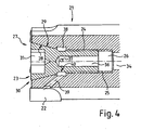
- the diameter of a cutting head 21 with cutting plates 22 (see in particular FIG. 4 ) on the second Schaffteil 3 adjustable is screwed with an external thread 24 into a matching internal thread 25 of a bore 26 from an end face 27 of the cutting head 21.
- the adjusting screw 23 has an outer cone 28 which forms a conical seat 30 with a mating inner cone 29 on the second shaft part 3. Due to the bracing state of the conical seat 30, the inner cone 29 can be widened more or less strongly, as a result of which a machining diameter on which the cutting plates 22 run can likewise be adjusted.
- Both the conical seat 10 and the conical seat 30 are preferably matched to one another so that first the sections of the respective inner cone 13, 29 positioned at the respective cutting head 5, 21 first come to rest, so that there defines a diameter widening by screwing in the respective outer cone 11 , 28 is reachable.
- the adjusting screw 23 can be screwed in, for example, via an inner seat edge 31.
- Another essential aspect of the devisnreibahle 1 lies in the coolant / lubricant guide.
- coolant / lubricant passes from a spindle into a first section 33 of the passage 9 in the inserted state.
- transfer takes place into a cooling passage 34 of the second shaft part 3
- a cross-connection 35 be provided to the recess 12, of which connections, not shown, are realized to outlets in the region of the respective cutting plates 6. This can be done a targeted cooling / lubrication of the cutting plates 6 in the case of processing.
- a portion 34 a of the cooling channel 34 completely penetrates the second shaft part 3. At the end face 27 of the second shaft part 3, however, the passage 34 is closed by the adjusting screw 23.
- the adjusting screw 23 in turn has a central bore 36, with cross connections 37 to a franking 38 on the second shaft part 3, from which preferably oblique stub lines 39 to each cutting plate 22.
- the adjusting screw 23 is tapered at this point by a feeder 40.
- Step reamer 2 first shaft part 3 second shaft part 4 Positive taper 5 cutting head 6 cutting board 7 recess 8th flute 9 passage 10 conical seat 11 outer cone 12 puncture 13 inner cone 14 cylindrical section 15 cylindrical section 16 inner thread 17 cylindrical section 18 external thread 19 two Kant 20 two Kant 21 cutting head 22 cutting board 23 adjustment 24 external thread 25 inner thread 26 drilling 27 front 28 outer cone 29 inner cone 30 conical seat 31 Allen 32 overset 33 section 34 cooling channel 34a section 35 cross connection 36 drilling 37 cross-device 38 franking 39 stubs 40 collection
Landscapes
- Engineering & Computer Science (AREA)
- Mechanical Engineering (AREA)
- Milling, Broaching, Filing, Reaming, And Others (AREA)
- Harvester Elements (AREA)
Description
- Die Erfindung betrifft ein rotierendes Schaftwerkzeug wie es aus der
DE 20 2006 004 719 U1 bekannt ist. - Aus dem deutschen Gebrauchsmuster
DE 20 2006 004 719 U1 ist eine Stufenreibahle bekannt, die ein erstes Schaftteil umfasst, an dem ein erster Schneidkopf mit Schneiden ausgebildet ist, wobei in einer Ausnehmung im ersten Schaftteil ein zweites Schaftteil mit kleinerem Durchmesser sitzt, an welchem ein zweiter Schneidkopf ausgebildet ist. Zwischen dem ersten und dem zweiten Schaftteil ist ein konischer Sitz ausgeformt. Des Weiteren sind Einstellmittel vorgesehen, mit welchen die Verspannkraft des konischen Sitzes veränderbar ist, womit der Fügezustand des konischen Sitzes eingestellt werden kann. Dadurch lässt sich der Durchmesser des Schneidkopfes vom ersten Schaftteil einstellen. - Als Einstellmittel läuft ein Zuganker vom Schaftteil.
- Der Erfindung liegt die Aufgabe zu Grunde, ein Schaftwerkzeug mit einstellbarem Schneiddurchmesser bereitzustellen, das eine verbesserte Handhabung ermöglicht.
- Diese Aufgabe wird durch die Merkmale des Anspruchs 1 gelöst.
- In den abhängigen Ansprüchen sind vorteilhafte und zweckmäßige Weiterbildungen der Erfindung beschrieben.
- Wie beansprucht, wird ein rotierbares Schaftwerkzeug, insbesondere Stufenreibahle, vorgeschlagen, welches ein erstes Schaftteil, an dem ein erster Schneidkopf mit wenigstens einer Schneide und mit einstellbarem Durchmesser ausgebildet ist, und ein zweites Schaftteil, an dem ein zweiter Schneidkopf mit wenigstens einer Schneide vorgesehen ist. Das zweite Schaftteil kann in einer Ausnehmung im ersten Schaftteil in der Achse des ersten Schaftteils eingesetzt werden. Das erste Schaftteil weist einen zentralen Durchgang auf, bei dem im Bereich des ersten Schneidkopfs ein Konussitz mit einem Innenkonus und ein zylindrischer Abschnitt mit einem Innengewinde ausgebildet sind. Am zweiten Schaftteil ist ein dem Innenkonus entsprechender Außenkonus und ein zylindrischer Abschnitt mit einem Außengewinde ausgebildet.
- Erfindungsgemäß ist das zweite Schaftteil verdrehbar in das erste Schaffteil einsetzbar. Dabei greifen im eingesetzten Zustand des zweiten Schaftteils der Außenkonus bzw. das Außengewinde des zweiten Schaftteils mit dem Innenkonus bzw. dem Innengewinde des ersten Schaftteils ineinander. Durch Anziehen der Verschraubung aus Innengewinde und Außengewinde wird der Außenkonus in den Innenkonus gezogen. Somit ist durch Verdrehung der Schaftteile zueinander ein fester Sitz des zweiten Schafteils in dem ersten Schaftteil ausbildbar.
- Vorzugsweise ist der Konussitz so ausgebildet, dass je nach Verspannzustand des Konussitzes durch ein Verdrehen des zweiten Schaftteils gegenüber dem ersten Schaftteil eine Einstellbarkeit eines Schneiddurchmessers des ersten Schneidkopfs in einem vorgegebenen Einstellbereich gegeben ist.
- Durch diese Maßnahme wird es möglich, eine Verbindung der beiden Schaftteile und insbesondere damit den Durchmesser des ersten Schneidkopfs zu verändern, obgleich das Schaftwerkzeug z.B. in einer Spindel einer Werkzeugmaschine eingesetzt ist. Denn eine Verdrehung des zweiten Schaftteil erfordert nicht zwingend Betätigungsbereiche, die in einem in eine Spindel eingesetzten Zustand des Schaftwerkzeugs nicht zugänglich wären.
- Zwischen dem ersten und dem zweiten Schaftteil ist ein konischer Sitz ausgeformt. Je nach Anpresskraft des konischen Sitzes lassen sich geometrische Verhältnisse einstellen. Sind im Sitzbereich z.B. die Schneiden des ersten Schaftteils positioniert, kann auf diese Weise der Durchmesser des ersten Schneidkopfs verändert werden.
- Das zweite Schaftteil ist in das erste Schaftteil einschraubbar. Damit kann z.B. je nach Einschraubkraft über den konischen Sitz eine Durchmesserveränderung des ersten Schneidkopfes erreicht werden.
- Zur Verdrehung der Schaftteile zueinander ist es im Weiteren bevorzugt, wenn am zweiten Schaftteil Eingreifmittel für ein Betätigungswerkzeug vorgesehen sind. Zum Beispiel sind planparallele Flächen für den Einsatz eines Gabelschlüssels ausgebildet.
- Im Weiteren ist es bevorzugt, wenn auch am ersten Schaftteil Eingreifmittel vorhanden sind, z.B. auch in Form von planparallelen Flächen für einen Gabelschlüssel. Damit lässt sich eine Verdrehkraft am zweiten Schaftteil über den Ansatz eines Betätigungswerkzeugs am ersten Schaftteil gegenhalten und umgekehrt.
- Somit lässt sich nach außen kraftneutral eine Verdrehung der Schaftteile zueinander vornehmen. Entsprechende Eingreifmittel für ein Betätigungswerkzeug sind vorzugsweise auch bei einem in einer Spindel montiertem Zustand des Schaftwerkzeugs zugänglich, so dass im Montagezustand eine Verdrehung der Schaftteile zueinander mit der Möglichkeit der Einstellung des Durchmessers des ersten Schneidkopfs vorhanden ist.
- Vorzugsweise ist im zweiten Schaftteil ein Kühlkanal vorhanden, der einen Auslass im Bereich des zweiten Schneidkopfs besitzt. Vorzugsweise ist im ersten Schaftteil ebenfalls ein Kühlkanal ausgebildet, der mit dem Kühlkanal im zweiten Schaftteil in Verbindung steht. Damit kann der zweite Schneidkopf zentral mit Kühl-/Schmiermittel versorgt werden.
- In einer bevorzugten Ausgestaltung weist der Kühlkanal im zweiten Schaftteil einen entlang des Schaftes verlaufenden Kühlkanalabschnitt und einen von der Achse des zweiten Schaftteils nach außen laufenden Kühlkanalabschnitt auf, der im Bereich einer Schneide des zweiten Schneidkopfs einen Auslass besitzt. In einem Fall, in welchem mehrere Schneiden am Schneidkopf angeordnet sind, ist vorzugsweise ein nach außen verlaufender Kühlkanalabschnitt in den Bereich einer jeden Schneide geführt. Damit lässt sich eine bestmögliche Schmierung/Kühlung der Schneiden im Arbeitseinsatz erreichen. Zum Beispiel sind nach außen verlaufende Kühlkanalabschnitte als schräg zur Achse angeordnete Kühlkanalabschnitte ausgebildet, die einen Auslass im Bereich einer Schneide besitzen.
- In einer bevorzugten Ausgestaltung ist im zweiten Schaftteil in der Stirnseite des Schneidkopfes ein Schraubenelement vorgesehen, in welchem ein Kühlkanalabschnitt ausgebildet ist, der mit einem Kühlkanalabschnitt in Verbindung steht, welcher insbesondere zentral im zweiten Schaftteil läuft. Durch den Einsatz eines Schraubenelements lässt sich die Führung des Kühlkanals im zweiten Schaftteil im Hinblick auf eine Herstellbarkeit vereinfachen.
- Das Schraubenelement schließt beispielsweise einen zentral im zweiten Schaftteil angeordneten Kühlkanalabschnitt an der Stirnseite ab, schafft jedoch bevorzugt gleichzeitig eine Verbindung des abgeschlossenen Kühlkanalabschnitts mit einem oder mehreren von der Achse nach außen laufenden Kühlkanalabschnitten, die insbesondere im Bereich der Schneiden des zweiten Schneidkopfs jeweils einen Auslass besitzen. Hierzu weist der Kühlkanalabschnitt im Schraubenelement z.B. Verbindungsabschnitte auf, die einen Auslass in einer Freimachung in einem Wandungsabschnitt des zweiten Schaftteils besitzen, von dem die von der Achse nach außen laufenden Kühlkanalabschnitte im zweiten Schaftteil ausgehen. Diese Betrachtung setzt den Montagezustand des Schraubenelements im zweiten Schaftteil voraus.
- Die Freimachung, z.B. ein Einstich in der Wandung des zweiten Schaftteils, ist vorzugsweise derart bemessen, dass in sinnvollen Montagelagen des Schraubenelements, das z.B. für die Einstellung unterschiedlicher Durchmesser des zweiten Schneidkopfs über einen Konussitz verschiedene Lagen einnehmen kann, eine Verbindung einer z.B. zentral im zweiten Schaftteil verlaufenden Kühlkanalabschnitts zu den nach außen laufenden Kühlkanalabschnitten immer gewährleistet ist.
- Ein Ausführungsbeispiel der Erfindung ist anhand von mehreren Zeichnungen nachstehend unter Angabe weiterer Vorteile und Einzelheiten näher erläutert.
- Es zeigen:
- Figur 1
- eine erfindungsgemäße Mehrstufenreibahle in einer Seitenansicht,
- Figur 2
- die Stufenreibahle aus
Figur 1 in einer Draufsicht, - Figur 3
- die Stufenreibahle aus
Figur 1 in einer geschnittenen Seitenansicht entlang der Achse des Werkzeugs und - Figur 4
- eine vergrößerte Darstellung des vorderen Abschnitts der Mehrstufenreibahle gemäß der Schnittansicht nach
Figur 3 . - In den Figuren ist eine Stufenreibahle 1 dargestellt, die ein erstes Schaftteil 2 sowie ein zweites Schaftteil 3 umfasst. Am ersten Schaftteil 2 ist ein Hohlschaftkegel 4 für die Anbringung an eine Werkzeugmaschine ausgebildet.
- Am ersten Schaftteil 2 ist ein Schneidkopf 5 vorhanden, der z.B. PKD-Schneidplatten 6 (polykristalliner Diamant) besitzt, die in entsprechenden Ausnehmungen 7 angeordnet sind. Den PKD-Schneidplatten 6 sind Spannuten 8 zugeordnet. Insgesamt sind über den Umfang des Scheidkopfes 5 sechs Schneidplatten 6 verteilt.
- Das erste Schaftteil 2 weist einen zentralen Durchgang 9 auf, der im Bereich des Schneidkopfes 5 einen Konussitz 10 mit einem Innenkonus 13 und einem entsprechenden Außenkonus 11 am zweiten Schaftteil 3 ausbildet.
- Durch einen Einstich 12 geht der Innenkonus 13 am ersten Schaftteil 2 des Konussitzes 10 in zwei zylindrische Abschnitte 14 und 15 über, wobei am zylindrischen Abschnitt 15 ein Innengewinde 16 ausgebildet ist. In das Innengewinde 16 ist ein zylindrischer Abschnitt 17 mit Außengewinde 18 des zweiten Schaftteils 3 eingeschraubt. Durch Anziehen der Verschraubung aus Innengewinde 16 und Außengewinde 18 wird der Außenkonus 11 in den Innenkonus 13 gezogen, so dass ein fester Sitz des zweiten Schaftteils 3 im ersten Schaftteil 2 ausgebildet wird.
- Je nach Verspannzustand des Konussitzes 10 durch ein Verdrehen des zweiten Schaftteils 3 gegenüber dem ersten Schaftteil 2 ist eine Einstellbarkeit eines Schneiddurchmessers, auf welchem die Schneidplatten 6 laufen, in einem gewissen Einstellbereich gegeben.
- Um das zweite Schaftteil 3 gegenüber dem ersten Schaftteil 2 verdrehen zu können, ist sowohl am ersten Schaftteil 2 als auch am zweiten Schaftteil 3 ein Zweikant 19 bzw. 20 vorhanden, in welchem sich Gabelschlüssel ansetzen lassen. Der erste Zweikant 19 hat z.B. eine Schlüsselweite von 21. Der zweite Zweikant 20 am zweiten Schaftteil 3 weist beispielsweise eine Schlüsselweite von 13 auf. Damit ist es möglich, nach außen kraftneutral durch entsprechendes Gegenhalten mit Gabelschlüsseln die Spannung der Verschraubung des ersten Schaftteils mit dem zweiten Schaftteil einzustellen. Dies kann auch dann erfolgen, wenn die Stufenreibahle 1 mit ihrem Hohlschaftkegel 4 bereits in einer Spindel sitzt, ggf. während einer Unterbrechung einer laufenden Bearbeitung, um den Durchmesser des Schneidkopfs 5 nachzujustieren.
- Im Ausführungsbeispiel ist auch der Durchmesser eines Schneidkopfs 21 mit Schneidplatten 22 (siehe insbesondere
Figur 4 ) am zweiten Schaffteil 3 justierbar. Hierzu ist eine Einstellschraube 23 mit einem Außengewinde 24 in ein dazu passendes Innengewinde 25 einer Bohrung 26 von einer Stirnseite 27 des Schneidkopfs 21 eingeschraubt. - Die Einstellschraube 23 besitzt einen Außenkonus 28, der mit einem dazu passenden Innenkonus 29 am zweiten Schaftteil 3 einen Konussitz 30 bildet. Durch den Verspannzustand des Konussitzes 30 kann der Innenkonus 29 stärker oder weniger stark aufgeweitet werden, wodurch sich ein Bearbeitungsdurchmesser, auf welchem die Schneidplatten 22 laufen, ebenfalls justieren lässt. Sowohl der Konussitz 10 als auch der Konussitz 30 sind vorzugsweise so aufeinander abgestimmt, dass zunächst die am jeweiligen Schneidkopf 5, 21 stirnseitig positionierten Abschnitte des jeweiligen Innenkonus 13, 29 zuerst zur Anlage kommen, so dass dort definiert eine Durchmesseraufweitung durch Eindrehen des jeweiligen Außenkonus 11, 28 erreichbar ist.
- Die Einstellschraube 23 kann z.B. über einen Innensitzkant 31 eingeschraubt werden.
- Ein weiterer wesentlicher Aspekt der Stufenreibahle 1 liegt in der Kühl-/Schmiermittelführung.
- Über einen Übergabesatz 32, der aus dem Stand der Technik bekannt ist, gelangt z.B. von einer Spindel in eingesetztem Zustand Kühl-/Schmiermittel in einen ersten Abschnitt 33 des Durchgangs 9. Im zylindrischen Abschnitt 15 erfolgt eine Übergabe in einen Kühlkanal 34 des zweiten Schaftteils 3. Auf der Höhe des Einstichs 12 im ersten Schaftteil 2 kann, wie in
Figur 3 ersichtlich, eine Querverbindung 35 zum Einstich 12 vorgesehen sein, von welchem nicht dargestellte Verbindungen zu Auslässen im Bereich der jeweiligen Schneidplatten 6 realisiert sind. Damit kann eine gezielte Kühlung/Schmierung der Schneidplatten 6 im Bearbeitungsfall erfolgen. - Ein Abschnitt 34a des Kühlkanals 34 durchdringt den zweiten Schaftteil 3 vollständig. An der Stirnseite 27 des zweiten Schaftteils 3 ist der Durchgang 34 jedoch durch die Einstellschraube 23 verschlossen.
- Die Einstellschraube 23 weist ihrerseits eine zentrale Bohrung 36 auf, mit Querverbindungen 37 zu einer Freimachung 38 am zweiten Schaftteil 3, von welcher vorzugsweise zu jeder Schneidplatte 22 schräge Stichleitungen 39 abgehen. Um dem Kühl-/Schmiermittel genügend Platz für die Verteilung in die Stichkanäle 39 zu verschaffen, ist z.B. die Einstellschraube 23 an dieser Stelle durch einen Einzug 40 verjüngt. Durch diese Maßnahme kann zielgenau Kühl-/Schmiermittel im Bearbeitungseinsatz zu jeder Schneidplatte 22 geführt werden.
-
1 Stufenreibahle 2 erstes Schaftteil 3 zweites Schaftteil 4 Hohlschaftkegel 5 Schneidkopf 6 Schneidplatte 7 Ausnehmung 8 Spannut 9 Durchgang 10 Konussitz 11 Außenkonus 12 Einstich 13 Innenkonus 14 zylindrischer Abschnitt 15 zylindrischer Abschnitt 16 Innengewinde 17 zylindrischer Abschnitt 18 Außengewinde 19 Zweikant 20 Zweikant 21 Schneidkopf 22 Schneidplatte 23 Einstellschraube 24 Außengewinde 25 Innengewinde 26 Bohrung 27 Stirnseite 28 Außenkonus 29 Innenkonus 30 Konussitz 31 Innensechskant 32 Übersatz 33 Abschnitt 34 Kühlkanal 34a Abschnitt 35 Querverbindung 36 Bohrung 37 Quervorrichtung 38 Freimachung 39 Stichleitungen 40 Einzug
Claims (11)
- Rotierbares Schaftwerkzeug, insbesondere Stufenreibahle (1), umfassend ein erstes Schaftteil (2), an dem ein erster Schneidkopf (5) mit wenigstens einer Schneide (6) ausgebildet ist, und ein zweites Schaftteil (3), an dem ein zweiter Schneidkopf (21) mit wenigstens einer Schneide (22) vorgesehen ist, wobei in einer Ausnehmung (9) im ersten Schaftteil (2) das zweite Schaftteil (3) in der Achse des ersten Schaftteils (2) eingesetzt werden kann, wobei der Durchmesser des ersten Schneidkopfs (5) einstellbar ist,wobei das erste Schaftteil (2) einen zentralen Durchgang (9) aufweist, bei dem im Bereich des ersten Schneidkopfs (5) ein Konussitz (10) mit einem Innenkonus (13) und ein zylindrischer Abschnitt (15) mit einem Innengewinde (16) ausgebildet sind, undwobei am zweiten Schaftteil (3) ein dem Innenkonus (13) entsprechender Außenkonus (11) und ein zylindrischer Abschnitt (17) mit einem Außengewinde (18) ausgebildet ist,wobei das zweite Schaftteil (3) verdrehbar in das erste Schaffteil (2) einsetzbar ist,wobei im eingesetzten Zustand des zweiten Schaftteils (3) der Außenkonus (11) bzw. das Außengewinde (18) des zweiten Schaftteils (3) mit dem Innenkonus (13) bzw. dem Innengewinde (16) des ersten Schaftteils ineinander greifen, undwobei durch Anziehen der Verschraubung aus Innengewinde (16) und Außengewinde (18) der Außenkonus (11) in den Innenkonus (13) gezogen wird, so dass durch Verdrehung der Schaftteile (2, 3) zueinander ein fester Sitz des zweiten Schafteils in dem ersten Schaftteil (2) ausbildbar ist.
- Schaftwerkzeug nach Anspruch 1, dadurch gekennzeichnet, dass je nach Verspannzustand des Konussitzes (10) durch ein Verdrehen des zweiten Schaftteils (3) gegenüber dem ersten Schaftteil (2) eine Einstellbarkeit eines Schneiddurchmessers des ersten Schneidkopfs (5) in einem vorgegebenen Einstellbereich gegeben ist.
- Schaftwerkzeug nach Anspruch 1 oder 2, dadurch gekennzeichnet, dass das zweite Schaftteil (3) in das erste Schaftteil (2) einschraubbar ist.
- Schaftwerkzeug nach einem der vorhergehenden Ansprüche, dadurch gekennzeichnet, dass am zweiten Schaftteil (3) Eingreifmittel (20) für ein erstes Betätigungswerkzeug vorgesehen sind.
- Schaftwerkzeug nach einem der vorhergehenden Ansprüche, dadurch gekennzeichnet, dass am ersten Schaftteil (2) Eingreifmittel (19) für ein zweites Betätigungswerkzeug vorgesehen sind.
- Schaftwerkzeug nach dem Oberbegriff des Anspruchs 1, insbesondere nach einem der vorhergehenden Ansprüche, dadurch gekennzeichnet, dass im zweiten Schaffteil (3) ein Kühlkanal (34) vorhanden ist, der einen Auslass im Bereich des zweiten Schneidkopfs (21) besitzt.
- Schaftwerkzeug nach Anspruch 6, dadurch gekennzeichnet, dass der Kühlkanal (34) im zweiten Schaftteil (3) einen entlang des Schafts verlaufenden Kühlkanalabschnitt (34a) und einen von der Achse des zweiten Schaftteils (3) nach aussen verlaufenden Kühlkanalabschnitt (39) aufweist, der im Bereich einer Schneide (22) des zweiten Schneidkopfs (21) einen Auslass besitzt.
- Schaftwerkzeug nach einem der vorhergehenden Ansprüche, dadurch gekennzeichnet, dass im zweiten Schaftteil (3) in der Stirnseite (27) des Schneidkopfes (21) ein Schraubenelement (23) vorgesehen ist, in welchem ein Kühlkanalabschnitt (36) ausgebildet ist, der mit einem Kühlkanalabschnitt (34a) in Verbindung steht, welcher im zweiten Schaftteil (3) läuft.
- Schaftwerkzeug nach einem der vorhergehenden Ansprüche, dadurch gekennzeichnet, dass der Kühlkanalabschnitt (36) im Schraubenelement (23) den im zweiten Schaftteil (3) angeordneten Kühlkanalabschnitt (34a) mit dem von der Achse nach außen verlaufenden Kühlkanalabschnitt (39) verbindet.
- Schaftwerkzeug nach einem der vorhergehenden Ansprüche, dadurch gekennzeichnet, dass in einem Wandungsabschnitt des zweiten Schaftteils (3) eine Freimachung (38) vorgesehen ist, von der der von der Achse nach außen verlaufende Kühlkanalabschnitt (39) ausgeht.
- Schaftwerkzeug nach einem der vorhergehenden Ansprüche, dadurch gekennzeichnet, dass der Kühlkanalabschnitt (36) im Schraubenelement (23) in einem im zweiten Schaftteil (3) eingesetzten Montagezustand eine Verbindung zu der Freimachung (38) umfasst.
Applications Claiming Priority (2)
| Application Number | Priority Date | Filing Date | Title |
|---|---|---|---|
| DE202007015595U DE202007015595U1 (de) | 2007-11-07 | 2007-11-07 | Rotierendes Schaftwerkzeug, insbesondere Stufenreibahle |
| PCT/DE2008/001648 WO2009059576A2 (de) | 2007-11-07 | 2008-10-14 | Rotierendes schaftwerkzeug, insbesondere stufenreibahle |
Publications (2)
| Publication Number | Publication Date |
|---|---|
| EP2205390A2 EP2205390A2 (de) | 2010-07-14 |
| EP2205390B1 true EP2205390B1 (de) | 2013-06-05 |
Family
ID=38989977
Family Applications (1)
| Application Number | Title | Priority Date | Filing Date |
|---|---|---|---|
| EP08848449.8A Active EP2205390B1 (de) | 2007-11-07 | 2008-10-14 | Rotierendes schaftwerkzeug, insbesondere stufenreibahle |
Country Status (7)
| Country | Link |
|---|---|
| US (1) | US8157488B2 (de) |
| EP (1) | EP2205390B1 (de) |
| JP (1) | JP5520827B2 (de) |
| KR (1) | KR101516228B1 (de) |
| CN (1) | CN101855038A (de) |
| DE (1) | DE202007015595U1 (de) |
| WO (1) | WO2009059576A2 (de) |
Families Citing this family (17)
| Publication number | Priority date | Publication date | Assignee | Title |
|---|---|---|---|---|
| KR101688178B1 (ko) | 2009-03-30 | 2016-12-20 | 귀링 오하게 | 회전 구동형 멀티 베벨 스텝 공구 |
| DE102009035690A1 (de) * | 2009-07-30 | 2011-02-03 | Zettl GmbH CNC Präzisions- und Sonderwerkzeuge | Maschinenreibahle |
| DE102009042395A1 (de) | 2009-09-16 | 2011-03-24 | Hartmetall-Werkzeugfabrik Paul Horn Gmbh | Reibwerkzeug zur spanenden Bearbeitung eines Werkstücks |
| JP2011206885A (ja) * | 2010-03-30 | 2011-10-20 | Honda Motor Co Ltd | 孔あけ加工工具及び孔あけ加工方法 |
| JP5813092B2 (ja) * | 2010-04-03 | 2015-11-17 | グーリング オーハーゲー | コレットチャック |
| DE102010014322B4 (de) * | 2010-04-09 | 2015-04-23 | Kennametal Inc. | Werkzeugkopf für ein rotierendes Werkzeug |
| DE102010018254B4 (de) * | 2010-04-23 | 2022-11-10 | Kennametal Inc. | Kühlmittelverteiler |
| DE102012216655A1 (de) * | 2012-09-18 | 2014-03-20 | Gühring KG | Drehantreibbares zerspanungswerkzeug |
| EP2745963B2 (de) | 2012-12-19 | 2021-03-17 | Seco Tools Ab | Ankopplung für ein Kühlungssystem in einem Schneidwerkzeug |
| DE102013105015A1 (de) | 2013-05-15 | 2014-11-20 | Gühring KG | Systemwerkzeug und Werkzeug zur spanabhebenden Bearbeitung |
| CN103447620A (zh) * | 2013-09-09 | 2013-12-18 | 昆山奥德鲁自动化技术有限公司 | 一种手持多用铰刀 |
| CN103495774A (zh) * | 2013-09-29 | 2014-01-08 | 大连机床(数控)股份有限公司 | 内冷式铰挤刀 |
| CN103878441A (zh) * | 2014-03-05 | 2014-06-25 | 郑州市钻石精密制造有限公司 | 一种防缩孔铰刀 |
| CN106312189A (zh) * | 2016-09-29 | 2017-01-11 | 江苏中晟钻石工具有限公司 | 一种pcd铰刀 |
| US10486253B2 (en) | 2017-01-04 | 2019-11-26 | Kennametal Inc. | Metal-cutting tool, in particular a reaming tool and method of making the same |
| CN111408746A (zh) * | 2020-05-18 | 2020-07-14 | 襄阳顺裕铸造有限公司 | 一种多工位pcd成型刀 |
| CN113333836B (zh) * | 2021-05-28 | 2024-01-09 | 江苏锋宝冶金设备有限公司 | 一种刀具防损刀刃及其冷却装置 |
Citations (1)
| Publication number | Priority date | Publication date | Assignee | Title |
|---|---|---|---|---|
| US5326196A (en) * | 1993-06-21 | 1994-07-05 | Noll Robert R | Pilot drill bit |
Family Cites Families (24)
| Publication number | Priority date | Publication date | Assignee | Title |
|---|---|---|---|---|
| US1074820A (en) * | 1912-12-20 | 1913-10-07 | Charles O Schellenbach | Expansion-reamer. |
| US1127121A (en) * | 1914-05-11 | 1915-02-02 | Wahlstrom Tool Company | Expanding reamer. |
| US1117946A (en) * | 1914-08-31 | 1914-11-17 | Samuel Alexander Fox | Adjustable reamer. |
| US1240553A (en) * | 1916-05-15 | 1917-09-18 | Ira W Foltz | Drill. |
| US1512339A (en) * | 1922-05-15 | 1924-10-21 | Johnson Robert | Expansion reamer |
| US1697509A (en) * | 1924-02-20 | 1929-01-01 | Jr John M Marty | Expansible reamer |
| US1774701A (en) * | 1928-01-18 | 1930-09-02 | Frederick H Davenport | Expanding reamer |
| US2381899A (en) * | 1943-08-21 | 1945-08-14 | James H Gracey | Expansion reamer |
| US2556372A (en) * | 1946-11-06 | 1951-06-12 | Robert C Johnston | Expansible device for tapping or reaming holes |
| US2623422A (en) * | 1950-06-02 | 1952-12-30 | Jr James E Billingsley | Reaming tool with removable blades |
| US3364800A (en) * | 1965-05-07 | 1968-01-23 | Erickson Tool Co | Mist coolant spade drill |
| CH666643A5 (en) * | 1985-07-29 | 1988-08-15 | Polytool Ag | Reamer with cutting head of adjustable dia. - has bolt with conical head which expands reamer dia. |
| ATE42702T1 (de) * | 1985-09-16 | 1989-05-15 | Dihart Ag | Reibahle mit kuehlmittelzufuhr. |
| DE19719892A1 (de) * | 1997-05-12 | 1998-11-19 | Maier Kg Andreas | Feinstbearbeitungswerkzeug |
| US6394711B1 (en) * | 2000-03-28 | 2002-05-28 | Tri-Cel, Inc. | Rotary cutting tool and holder therefor |
| JP2003136322A (ja) * | 2001-10-25 | 2003-05-14 | Jatco Ltd | 穴加工工具 |
| US7431543B2 (en) * | 2002-02-15 | 2008-10-07 | Dihart Ag | Machine reamer |
| IL150013A (en) * | 2002-06-04 | 2007-06-17 | Gil Hecht | Rotary cutting tool |
| JP3849096B2 (ja) * | 2002-07-18 | 2006-11-22 | ホーコス株式会社 | 工作機械の工具ホルダ |
| DE102005028368A1 (de) * | 2005-06-20 | 2006-12-28 | MAPAL Fabrik für Präzisionswerkzeuge Dr. Kress KG | Ventilsitz- und Ventilführungsbearbeitungswerkzeug |
| DE102005031683A1 (de) * | 2005-07-05 | 2007-01-25 | Dihart Ag | Maschinenwerkzeug |
| DE202006004719U1 (de) * | 2006-02-15 | 2007-07-05 | Gühring Ohg | Rotierendes Schaftwerkzeug, insbesondere Stufenreibahle |
| JP4775065B2 (ja) * | 2006-03-27 | 2011-09-21 | 三菱マテリアル株式会社 | 穴加工工具 |
| SE532394C2 (sv) * | 2007-06-04 | 2010-01-12 | Sandvik Intellectual Property | Verktyg för spånavskiljande bearbetning samt grundkropp härför |
-
2007
- 2007-11-07 DE DE202007015595U patent/DE202007015595U1/de not_active Expired - Lifetime
-
2008
- 2008-10-14 EP EP08848449.8A patent/EP2205390B1/de active Active
- 2008-10-14 WO PCT/DE2008/001648 patent/WO2009059576A2/de not_active Ceased
- 2008-10-14 CN CN200880115176A patent/CN101855038A/zh active Pending
- 2008-10-14 JP JP2010532420A patent/JP5520827B2/ja active Active
- 2008-10-14 KR KR1020107012401A patent/KR101516228B1/ko not_active Expired - Fee Related
-
2010
- 2010-05-07 US US12/775,936 patent/US8157488B2/en not_active Expired - Fee Related
Patent Citations (1)
| Publication number | Priority date | Publication date | Assignee | Title |
|---|---|---|---|---|
| US5326196A (en) * | 1993-06-21 | 1994-07-05 | Noll Robert R | Pilot drill bit |
Also Published As
| Publication number | Publication date |
|---|---|
| JP5520827B2 (ja) | 2014-06-11 |
| JP2011502802A (ja) | 2011-01-27 |
| WO2009059576A2 (de) | 2009-05-14 |
| US20100254777A1 (en) | 2010-10-07 |
| CN101855038A (zh) | 2010-10-06 |
| EP2205390A2 (de) | 2010-07-14 |
| KR101516228B1 (ko) | 2015-05-04 |
| KR20100103497A (ko) | 2010-09-27 |
| DE202007015595U1 (de) | 2008-01-31 |
| WO2009059576A3 (de) | 2009-09-03 |
| US8157488B2 (en) | 2012-04-17 |
Similar Documents
| Publication | Publication Date | Title |
|---|---|---|
| EP2205390A2 (de) | Rotierendes schaftwerkzeug, insbesondere stufenreibahle | |
| EP2318166B1 (de) | Werkzeug für spanende bearbeitung eines werkstücks | |
| EP1474258B1 (de) | Maschinenreibahle | |
| EP2560778B1 (de) | Bohrkopf für ein tiefbohrwerkzeug zum bta-tiefbohren und tiefbohrwerkzeug | |
| DE102017205166B4 (de) | Modulares Rotationswerkzeug und modulares Werkzeugsystem | |
| WO2013117431A1 (de) | Einschraubwerkzeug und werkzeugaufnahme für ein derartiges einschraubwerkzeug | |
| EP2196273B2 (de) | Schnittstelle zwischen einem rundlaufenden Schaftwerkzeug und einer Schmiermittel-Übergabestelle in einer Werkzeugaufnahme | |
| DE10112966A1 (de) | Verbindungsstelle | |
| DE102009041812B4 (de) | Fräser mit einer schaftartigen Grundform | |
| EP3414038B1 (de) | Bohrwerkzeug | |
| DE102005029758B3 (de) | Schnittstelle eines Werkzeugsystems | |
| WO2007093169A2 (de) | Rotierendes schaftwerkzeug, insbesondere stufenreibahle | |
| DE102009044995B4 (de) | Schneideinsatzträger, Schneideinsatzund drehangetriebenes Schneidwerkzeug | |
| EP1896209A1 (de) | Ventilsitz- und ventilführungsbearbeitungswerkzeug | |
| EP1896206A1 (de) | Schnittstelle eines werkzeugsystems | |
| EP2298483B1 (de) | Reibahle und System zu Feinbearbeitung von Bohrungen mit einer solchen Reibahle und einem Einsatz | |
| EP2897751B1 (de) | Drehantreibbares spanabhebendes werkzeug | |
| EP2254715B1 (de) | Werkzeug | |
| DE10224228A1 (de) | Maschinenreibahle | |
| AT526727B1 (de) | Anordnung aus wenigstens einer Bohrkrone und wenigstens einem Anschlag | |
| EP0618028B1 (de) | Vorrichtung mit einem in einem Halter eingespannten und radial verschieblichen Zapfen oder Schaft | |
| WO2012156157A1 (de) | Tiefenanschlag in einem werkzeughalter für in dem werkzeughalter gehaltene materialbearbeitungswerkzeuge | |
| DE202006004719U1 (de) | Rotierendes Schaftwerkzeug, insbesondere Stufenreibahle | |
| WO2013026730A1 (de) | Kernlochbohrwerkzeug | |
| DE102019114042A1 (de) | Werkzeugadapter |
Legal Events
| Date | Code | Title | Description |
|---|---|---|---|
| PUAI | Public reference made under article 153(3) epc to a published international application that has entered the european phase |
Free format text: ORIGINAL CODE: 0009012 |
|
| 17P | Request for examination filed |
Effective date: 20100319 |
|
| AK | Designated contracting states |
Kind code of ref document: A2 Designated state(s): AT BE BG CH CY CZ DE DK EE ES FI FR GB GR HR HU IE IS IT LI LT LU LV MC MT NL NO PL PT RO SE SI SK TR |
|
| AX | Request for extension of the european patent |
Extension state: AL BA MK RS |
|
| DAX | Request for extension of the european patent (deleted) | ||
| 17Q | First examination report despatched |
Effective date: 20110308 |
|
| GRAP | Despatch of communication of intention to grant a patent |
Free format text: ORIGINAL CODE: EPIDOSNIGR1 |
|
| GRAP | Despatch of communication of intention to grant a patent |
Free format text: ORIGINAL CODE: EPIDOSNIGR1 |
|
| GRAS | Grant fee paid |
Free format text: ORIGINAL CODE: EPIDOSNIGR3 |
|
| GRAA | (expected) grant |
Free format text: ORIGINAL CODE: 0009210 |
|
| AK | Designated contracting states |
Kind code of ref document: B1 Designated state(s): AT BE BG CH CY CZ DE DK EE ES FI FR GB GR HR HU IE IS IT LI LT LU LV MC MT NL NO PL PT RO SE SI SK TR |
|
| REG | Reference to a national code |
Ref country code: GB Ref legal event code: FG4D Free format text: NOT ENGLISH |
|
| REG | Reference to a national code |
Ref country code: CH Ref legal event code: EP |
|
| REG | Reference to a national code |
Ref country code: AT Ref legal event code: REF Ref document number: 615350 Country of ref document: AT Kind code of ref document: T Effective date: 20130615 |
|
| REG | Reference to a national code |
Ref country code: IE Ref legal event code: FG4D Free format text: LANGUAGE OF EP DOCUMENT: GERMAN |
|
| REG | Reference to a national code |
Ref country code: DE Ref legal event code: R096 Ref document number: 502008010086 Country of ref document: DE Effective date: 20130801 |
|
| PG25 | Lapsed in a contracting state [announced via postgrant information from national office to epo] |
Ref country code: FI Free format text: LAPSE BECAUSE OF FAILURE TO SUBMIT A TRANSLATION OF THE DESCRIPTION OR TO PAY THE FEE WITHIN THE PRESCRIBED TIME-LIMIT Effective date: 20130605 Ref country code: ES Free format text: LAPSE BECAUSE OF FAILURE TO SUBMIT A TRANSLATION OF THE DESCRIPTION OR TO PAY THE FEE WITHIN THE PRESCRIBED TIME-LIMIT Effective date: 20130916 Ref country code: LT Free format text: LAPSE BECAUSE OF FAILURE TO SUBMIT A TRANSLATION OF THE DESCRIPTION OR TO PAY THE FEE WITHIN THE PRESCRIBED TIME-LIMIT Effective date: 20130605 Ref country code: GR Free format text: LAPSE BECAUSE OF FAILURE TO SUBMIT A TRANSLATION OF THE DESCRIPTION OR TO PAY THE FEE WITHIN THE PRESCRIBED TIME-LIMIT Effective date: 20130906 Ref country code: NO Free format text: LAPSE BECAUSE OF FAILURE TO SUBMIT A TRANSLATION OF THE DESCRIPTION OR TO PAY THE FEE WITHIN THE PRESCRIBED TIME-LIMIT Effective date: 20130905 Ref country code: SE Free format text: LAPSE BECAUSE OF FAILURE TO SUBMIT A TRANSLATION OF THE DESCRIPTION OR TO PAY THE FEE WITHIN THE PRESCRIBED TIME-LIMIT Effective date: 20130605 Ref country code: SI Free format text: LAPSE BECAUSE OF FAILURE TO SUBMIT A TRANSLATION OF THE DESCRIPTION OR TO PAY THE FEE WITHIN THE PRESCRIBED TIME-LIMIT Effective date: 20130605 |
|
| REG | Reference to a national code |
Ref country code: NL Ref legal event code: VDEP Effective date: 20130605 |
|
| REG | Reference to a national code |
Ref country code: LT Ref legal event code: MG4D |
|
| PG25 | Lapsed in a contracting state [announced via postgrant information from national office to epo] |
Ref country code: PL Free format text: LAPSE BECAUSE OF FAILURE TO SUBMIT A TRANSLATION OF THE DESCRIPTION OR TO PAY THE FEE WITHIN THE PRESCRIBED TIME-LIMIT Effective date: 20130605 Ref country code: HR Free format text: LAPSE BECAUSE OF FAILURE TO SUBMIT A TRANSLATION OF THE DESCRIPTION OR TO PAY THE FEE WITHIN THE PRESCRIBED TIME-LIMIT Effective date: 20130605 Ref country code: BG Free format text: LAPSE BECAUSE OF FAILURE TO SUBMIT A TRANSLATION OF THE DESCRIPTION OR TO PAY THE FEE WITHIN THE PRESCRIBED TIME-LIMIT Effective date: 20130905 |
|
| PG25 | Lapsed in a contracting state [announced via postgrant information from national office to epo] |
Ref country code: LV Free format text: LAPSE BECAUSE OF FAILURE TO SUBMIT A TRANSLATION OF THE DESCRIPTION OR TO PAY THE FEE WITHIN THE PRESCRIBED TIME-LIMIT Effective date: 20130605 |
|
| PG25 | Lapsed in a contracting state [announced via postgrant information from national office to epo] |
Ref country code: EE Free format text: LAPSE BECAUSE OF FAILURE TO SUBMIT A TRANSLATION OF THE DESCRIPTION OR TO PAY THE FEE WITHIN THE PRESCRIBED TIME-LIMIT Effective date: 20130605 Ref country code: CZ Free format text: LAPSE BECAUSE OF FAILURE TO SUBMIT A TRANSLATION OF THE DESCRIPTION OR TO PAY THE FEE WITHIN THE PRESCRIBED TIME-LIMIT Effective date: 20130605 Ref country code: PT Free format text: LAPSE BECAUSE OF FAILURE TO SUBMIT A TRANSLATION OF THE DESCRIPTION OR TO PAY THE FEE WITHIN THE PRESCRIBED TIME-LIMIT Effective date: 20131007 Ref country code: IS Free format text: LAPSE BECAUSE OF FAILURE TO SUBMIT A TRANSLATION OF THE DESCRIPTION OR TO PAY THE FEE WITHIN THE PRESCRIBED TIME-LIMIT Effective date: 20131005 Ref country code: SK Free format text: LAPSE BECAUSE OF FAILURE TO SUBMIT A TRANSLATION OF THE DESCRIPTION OR TO PAY THE FEE WITHIN THE PRESCRIBED TIME-LIMIT Effective date: 20130605 |
|
| REG | Reference to a national code |
Ref country code: DE Ref legal event code: R082 Ref document number: 502008010086 Country of ref document: DE Representative=s name: BODE MEITINGER PATENTANWALTSGESELLSCHAFT MBH, DE |
|
| PG25 | Lapsed in a contracting state [announced via postgrant information from national office to epo] |
Ref country code: RO Free format text: LAPSE BECAUSE OF FAILURE TO SUBMIT A TRANSLATION OF THE DESCRIPTION OR TO PAY THE FEE WITHIN THE PRESCRIBED TIME-LIMIT Effective date: 20130605 Ref country code: NL Free format text: LAPSE BECAUSE OF FAILURE TO SUBMIT A TRANSLATION OF THE DESCRIPTION OR TO PAY THE FEE WITHIN THE PRESCRIBED TIME-LIMIT Effective date: 20130605 |
|
| REG | Reference to a national code |
Ref country code: DE Ref legal event code: R082 Ref document number: 502008010086 Country of ref document: DE Representative=s name: BODE MEITINGER PATENTANWALTSGESELLSCHAFT MBH, DE Effective date: 20140203 Ref country code: DE Ref legal event code: R081 Ref document number: 502008010086 Country of ref document: DE Owner name: GUEHRING KG, DE Free format text: FORMER OWNER: GUEHRING OHG, 72458 ALBSTADT, DE Effective date: 20140203 |
|
| PLBE | No opposition filed within time limit |
Free format text: ORIGINAL CODE: 0009261 |
|
| STAA | Information on the status of an ep patent application or granted ep patent |
Free format text: STATUS: NO OPPOSITION FILED WITHIN TIME LIMIT |
|
| BERE | Be: lapsed |
Owner name: GUHRING OHG Effective date: 20131031 |
|
| PG25 | Lapsed in a contracting state [announced via postgrant information from national office to epo] |
Ref country code: DK Free format text: LAPSE BECAUSE OF FAILURE TO SUBMIT A TRANSLATION OF THE DESCRIPTION OR TO PAY THE FEE WITHIN THE PRESCRIBED TIME-LIMIT Effective date: 20130605 |
|
| 26N | No opposition filed |
Effective date: 20140306 |
|
| PG25 | Lapsed in a contracting state [announced via postgrant information from national office to epo] |
Ref country code: MC Free format text: LAPSE BECAUSE OF FAILURE TO SUBMIT A TRANSLATION OF THE DESCRIPTION OR TO PAY THE FEE WITHIN THE PRESCRIBED TIME-LIMIT Effective date: 20130605 Ref country code: IT Free format text: LAPSE BECAUSE OF FAILURE TO SUBMIT A TRANSLATION OF THE DESCRIPTION OR TO PAY THE FEE WITHIN THE PRESCRIBED TIME-LIMIT Effective date: 20130605 |
|
| REG | Reference to a national code |
Ref country code: CH Ref legal event code: PL |
|
| REG | Reference to a national code |
Ref country code: DE Ref legal event code: R097 Ref document number: 502008010086 Country of ref document: DE Effective date: 20140306 |
|
| GBPC | Gb: european patent ceased through non-payment of renewal fee |
Effective date: 20131014 |
|
| REG | Reference to a national code |
Ref country code: IE Ref legal event code: MM4A |
|
| PG25 | Lapsed in a contracting state [announced via postgrant information from national office to epo] |
Ref country code: LI Free format text: LAPSE BECAUSE OF NON-PAYMENT OF DUE FEES Effective date: 20131031 Ref country code: CH Free format text: LAPSE BECAUSE OF NON-PAYMENT OF DUE FEES Effective date: 20131031 Ref country code: GB Free format text: LAPSE BECAUSE OF NON-PAYMENT OF DUE FEES Effective date: 20131014 |
|
| REG | Reference to a national code |
Ref country code: FR Ref legal event code: ST Effective date: 20140630 |
|
| PG25 | Lapsed in a contracting state [announced via postgrant information from national office to epo] |
Ref country code: FR Free format text: LAPSE BECAUSE OF NON-PAYMENT OF DUE FEES Effective date: 20131031 |
|
| PG25 | Lapsed in a contracting state [announced via postgrant information from national office to epo] |
Ref country code: BE Free format text: LAPSE BECAUSE OF NON-PAYMENT OF DUE FEES Effective date: 20131031 |
|
| PG25 | Lapsed in a contracting state [announced via postgrant information from national office to epo] |
Ref country code: IE Free format text: LAPSE BECAUSE OF NON-PAYMENT OF DUE FEES Effective date: 20131014 |
|
| REG | Reference to a national code |
Ref country code: AT Ref legal event code: MM01 Ref document number: 615350 Country of ref document: AT Kind code of ref document: T Effective date: 20131014 |
|
| PG25 | Lapsed in a contracting state [announced via postgrant information from national office to epo] |
Ref country code: AT Free format text: LAPSE BECAUSE OF NON-PAYMENT OF DUE FEES Effective date: 20131014 |
|
| PG25 | Lapsed in a contracting state [announced via postgrant information from national office to epo] |
Ref country code: CY Free format text: LAPSE BECAUSE OF FAILURE TO SUBMIT A TRANSLATION OF THE DESCRIPTION OR TO PAY THE FEE WITHIN THE PRESCRIBED TIME-LIMIT Effective date: 20130605 Ref country code: TR Free format text: LAPSE BECAUSE OF FAILURE TO SUBMIT A TRANSLATION OF THE DESCRIPTION OR TO PAY THE FEE WITHIN THE PRESCRIBED TIME-LIMIT Effective date: 20130605 |
|
| PG25 | Lapsed in a contracting state [announced via postgrant information from national office to epo] |
Ref country code: HU Free format text: LAPSE BECAUSE OF FAILURE TO SUBMIT A TRANSLATION OF THE DESCRIPTION OR TO PAY THE FEE WITHIN THE PRESCRIBED TIME-LIMIT; INVALID AB INITIO Effective date: 20081014 Ref country code: LU Free format text: LAPSE BECAUSE OF NON-PAYMENT OF DUE FEES Effective date: 20131014 |
|
| PG25 | Lapsed in a contracting state [announced via postgrant information from national office to epo] |
Ref country code: MT Free format text: LAPSE BECAUSE OF FAILURE TO SUBMIT A TRANSLATION OF THE DESCRIPTION OR TO PAY THE FEE WITHIN THE PRESCRIBED TIME-LIMIT Effective date: 20130605 |
|
| REG | Reference to a national code |
Ref country code: DE Ref legal event code: R082 Ref document number: 502008010086 Country of ref document: DE Representative=s name: MEITINGER PATENTANWALTS GMBH, DE |
|
| PGFP | Annual fee paid to national office [announced via postgrant information from national office to epo] |
Ref country code: DE Payment date: 20251031 Year of fee payment: 18 |