EP2205303B1 - Medicinal inhalation devices and method of manufacture thereof - Google Patents
Medicinal inhalation devices and method of manufacture thereof Download PDFInfo
- Publication number
- EP2205303B1 EP2205303B1 EP20080847997 EP08847997A EP2205303B1 EP 2205303 B1 EP2205303 B1 EP 2205303B1 EP 20080847997 EP20080847997 EP 20080847997 EP 08847997 A EP08847997 A EP 08847997A EP 2205303 B1 EP2205303 B1 EP 2205303B1
- Authority
- EP
- European Patent Office
- Prior art keywords
- metal coating
- coating
- plasma
- component
- group
- Prior art date
- Legal status (The legal status is an assumption and is not a legal conclusion. Google has not performed a legal analysis and makes no representation as to the accuracy of the status listed.)
- Active
Links
- 238000000034 method Methods 0.000 title claims description 44
- 238000004519 manufacturing process Methods 0.000 title claims description 5
- 238000000576 coating method Methods 0.000 claims description 200
- 239000011248 coating agent Substances 0.000 claims description 150
- 239000000203 mixture Substances 0.000 claims description 106
- 229910052755 nonmetal Inorganic materials 0.000 claims description 89
- QVGXLLKOCUKJST-UHFFFAOYSA-N atomic oxygen Chemical compound [O] QVGXLLKOCUKJST-UHFFFAOYSA-N 0.000 claims description 63
- 229910052760 oxygen Inorganic materials 0.000 claims description 63
- 239000001301 oxygen Substances 0.000 claims description 63
- 238000000151 deposition Methods 0.000 claims description 58
- 230000008021 deposition Effects 0.000 claims description 53
- 150000001875 compounds Chemical class 0.000 claims description 51
- 229910052739 hydrogen Inorganic materials 0.000 claims description 50
- 239000001257 hydrogen Substances 0.000 claims description 50
- 125000000524 functional group Chemical group 0.000 claims description 48
- BLRPTPMANUNPDV-UHFFFAOYSA-N Silane Chemical group [SiH4] BLRPTPMANUNPDV-UHFFFAOYSA-N 0.000 claims description 44
- 229910052710 silicon Inorganic materials 0.000 claims description 41
- 239000010703 silicon Substances 0.000 claims description 41
- XUIMIQQOPSSXEZ-UHFFFAOYSA-N Silicon Chemical compound [Si] XUIMIQQOPSSXEZ-UHFFFAOYSA-N 0.000 claims description 38
- 229910052731 fluorine Inorganic materials 0.000 claims description 35
- 239000011737 fluorine Substances 0.000 claims description 35
- YCKRFDGAMUMZLT-UHFFFAOYSA-N Fluorine atom Chemical compound [F] YCKRFDGAMUMZLT-UHFFFAOYSA-N 0.000 claims description 32
- 238000010849 ion bombardment Methods 0.000 claims description 30
- 229910000077 silane Inorganic materials 0.000 claims description 28
- UFHFLCQGNIYNRP-UHFFFAOYSA-N Hydrogen Chemical compound [H][H] UFHFLCQGNIYNRP-UHFFFAOYSA-N 0.000 claims description 27
- OKTJSMMVPCPJKN-UHFFFAOYSA-N Carbon Chemical compound [C] OKTJSMMVPCPJKN-UHFFFAOYSA-N 0.000 claims description 26
- 229910052799 carbon Inorganic materials 0.000 claims description 26
- 239000011521 glass Substances 0.000 claims description 18
- 125000004432 carbon atom Chemical group C* 0.000 claims description 9
- 229940071648 metered dose inhaler Drugs 0.000 claims description 6
- 229910002808 Si–O–Si Inorganic materials 0.000 claims description 4
- 229940112141 dry powder inhaler Drugs 0.000 claims description 3
- 229910003849 O-Si Inorganic materials 0.000 claims description 2
- 229910003872 O—Si Inorganic materials 0.000 claims description 2
- 239000000758 substrate Substances 0.000 description 64
- 238000009472 formulation Methods 0.000 description 50
- 239000007789 gas Substances 0.000 description 43
- LFQSCWFLJHTTHZ-UHFFFAOYSA-N Ethanol Chemical compound CCO LFQSCWFLJHTTHZ-UHFFFAOYSA-N 0.000 description 30
- 239000000443 aerosol Substances 0.000 description 26
- 150000002500 ions Chemical class 0.000 description 24
- 239000003814 drug Substances 0.000 description 23
- 238000007906 compression Methods 0.000 description 20
- 230000006835 compression Effects 0.000 description 20
- IJGRMHOSHXDMSA-UHFFFAOYSA-N Atomic nitrogen Chemical compound N#N IJGRMHOSHXDMSA-UHFFFAOYSA-N 0.000 description 15
- 150000002431 hydrogen Chemical class 0.000 description 15
- 239000000463 material Substances 0.000 description 15
- 238000011282 treatment Methods 0.000 description 14
- OKKJLVBELUTLKV-UHFFFAOYSA-N Methanol Chemical compound OC OKKJLVBELUTLKV-UHFFFAOYSA-N 0.000 description 12
- 239000010453 quartz Substances 0.000 description 12
- VYPSYNLAJGMNEJ-UHFFFAOYSA-N silicon dioxide Inorganic materials O=[Si]=O VYPSYNLAJGMNEJ-UHFFFAOYSA-N 0.000 description 12
- 125000003545 alkoxy group Chemical group 0.000 description 11
- 229910052782 aluminium Inorganic materials 0.000 description 11
- XAGFODPZIPBFFR-UHFFFAOYSA-N aluminium Chemical compound [Al] XAGFODPZIPBFFR-UHFFFAOYSA-N 0.000 description 11
- 230000002349 favourable effect Effects 0.000 description 11
- 229910052751 metal Inorganic materials 0.000 description 11
- 239000002184 metal Substances 0.000 description 11
- -1 polypropylene Polymers 0.000 description 11
- 229910001220 stainless steel Inorganic materials 0.000 description 11
- 125000004178 (C1-C4) alkyl group Chemical group 0.000 description 10
- XKRFYHLGVUSROY-UHFFFAOYSA-N Argon Chemical compound [Ar] XKRFYHLGVUSROY-UHFFFAOYSA-N 0.000 description 10
- 125000004435 hydrogen atom Chemical group [H]* 0.000 description 10
- 239000003960 organic solvent Substances 0.000 description 10
- 238000009832 plasma treatment Methods 0.000 description 10
- 239000010935 stainless steel Substances 0.000 description 10
- XLYOFNOQVPJJNP-UHFFFAOYSA-N water Substances O XLYOFNOQVPJJNP-UHFFFAOYSA-N 0.000 description 10
- 229920000642 polymer Polymers 0.000 description 9
- 239000002904 solvent Substances 0.000 description 9
- SGHZXLIDFTYFHQ-UHFFFAOYSA-L Brilliant Blue Chemical compound [Na+].[Na+].C=1C=C(C(=C2C=CC(C=C2)=[N+](CC)CC=2C=C(C=CC=2)S([O-])(=O)=O)C=2C(=CC=CC=2)S([O-])(=O)=O)C=CC=1N(CC)CC1=CC=CC(S([O-])(=O)=O)=C1 SGHZXLIDFTYFHQ-UHFFFAOYSA-L 0.000 description 8
- 238000006243 chemical reaction Methods 0.000 description 8
- 239000003431 cross linking reagent Substances 0.000 description 8
- 150000002430 hydrocarbons Chemical group 0.000 description 8
- 239000004033 plastic Substances 0.000 description 8
- 229920003023 plastic Polymers 0.000 description 8
- 239000000843 powder Substances 0.000 description 8
- 238000005086 pumping Methods 0.000 description 8
- CZDYPVPMEAXLPK-UHFFFAOYSA-N tetramethylsilane Chemical compound C[Si](C)(C)C CZDYPVPMEAXLPK-UHFFFAOYSA-N 0.000 description 8
- 229910000838 Al alloy Inorganic materials 0.000 description 7
- NINIDFKCEFEMDL-UHFFFAOYSA-N Sulfur Chemical compound [S] NINIDFKCEFEMDL-UHFFFAOYSA-N 0.000 description 7
- 125000004423 acyloxy group Chemical group 0.000 description 7
- BNPSSFBOAGDEEL-UHFFFAOYSA-N albuterol sulfate Chemical compound OS(O)(=O)=O.CC(C)(C)NCC(O)C1=CC=C(O)C(CO)=C1.CC(C)(C)NCC(O)C1=CC=C(O)C(CO)=C1 BNPSSFBOAGDEEL-UHFFFAOYSA-N 0.000 description 7
- 229940057282 albuterol sulfate Drugs 0.000 description 7
- 125000004104 aryloxy group Chemical group 0.000 description 7
- 229940079593 drug Drugs 0.000 description 7
- 229910052757 nitrogen Inorganic materials 0.000 description 7
- 238000006116 polymerization reaction Methods 0.000 description 7
- 239000011593 sulfur Substances 0.000 description 7
- 229910052717 sulfur Inorganic materials 0.000 description 7
- CSCPPACGZOOCGX-UHFFFAOYSA-N Acetone Chemical compound CC(C)=O CSCPPACGZOOCGX-UHFFFAOYSA-N 0.000 description 6
- 230000015572 biosynthetic process Effects 0.000 description 6
- 238000009826 distribution Methods 0.000 description 6
- 229930195733 hydrocarbon Natural products 0.000 description 6
- 125000005647 linker group Chemical group 0.000 description 6
- 230000000284 resting effect Effects 0.000 description 6
- 150000004756 silanes Chemical class 0.000 description 6
- 229910052990 silicon hydride Inorganic materials 0.000 description 6
- 238000012360 testing method Methods 0.000 description 6
- 229910052786 argon Inorganic materials 0.000 description 5
- 125000003178 carboxy group Chemical group [H]OC(*)=O 0.000 description 5
- 150000002148 esters Chemical class 0.000 description 5
- 238000007667 floating Methods 0.000 description 5
- 125000002887 hydroxy group Chemical group [H]O* 0.000 description 5
- 229920001707 polybutylene terephthalate Polymers 0.000 description 5
- 230000037452 priming Effects 0.000 description 5
- 239000000523 sample Substances 0.000 description 5
- 238000007789 sealing Methods 0.000 description 5
- 239000000126 substance Substances 0.000 description 5
- LVGUZGTVOIAKKC-UHFFFAOYSA-N 1,1,1,2-tetrafluoroethane Chemical compound FCC(F)(F)F LVGUZGTVOIAKKC-UHFFFAOYSA-N 0.000 description 4
- SJECZPVISLOESU-UHFFFAOYSA-N 3-trimethoxysilylpropan-1-amine Chemical compound CO[Si](OC)(OC)CCCN SJECZPVISLOESU-UHFFFAOYSA-N 0.000 description 4
- QGZKDVFQNNGYKY-UHFFFAOYSA-N Ammonia Chemical compound N QGZKDVFQNNGYKY-UHFFFAOYSA-N 0.000 description 4
- VEXZGXHMUGYJMC-UHFFFAOYSA-N Hydrochloric acid Chemical compound Cl VEXZGXHMUGYJMC-UHFFFAOYSA-N 0.000 description 4
- KFZMGEQAYNKOFK-UHFFFAOYSA-N Isopropanol Chemical compound CC(C)O KFZMGEQAYNKOFK-UHFFFAOYSA-N 0.000 description 4
- DHKHKXVYLBGOIT-UHFFFAOYSA-N acetaldehyde Diethyl Acetal Natural products CCOC(C)OCC DHKHKXVYLBGOIT-UHFFFAOYSA-N 0.000 description 4
- 150000001241 acetals Chemical class 0.000 description 4
- 239000002253 acid Substances 0.000 description 4
- 239000012298 atmosphere Substances 0.000 description 4
- 125000004429 atom Chemical group 0.000 description 4
- 238000004891 communication Methods 0.000 description 4
- 238000006482 condensation reaction Methods 0.000 description 4
- 125000001153 fluoro group Chemical group F* 0.000 description 4
- 239000000989 food dye Substances 0.000 description 4
- 238000005259 measurement Methods 0.000 description 4
- 125000005515 organic divalent group Chemical group 0.000 description 4
- 238000012856 packing Methods 0.000 description 4
- 239000002245 particle Substances 0.000 description 4
- 125000005372 silanol group Chemical group 0.000 description 4
- 125000006850 spacer group Chemical group 0.000 description 4
- 238000003860 storage Methods 0.000 description 4
- AQRLNPVMDITEJU-UHFFFAOYSA-N triethylsilane Chemical compound CC[SiH](CC)CC AQRLNPVMDITEJU-UHFFFAOYSA-N 0.000 description 4
- 125000002023 trifluoromethyl group Chemical group FC(F)(F)* 0.000 description 4
- ZWEHNKRNPOVVGH-UHFFFAOYSA-N 2-Butanone Chemical compound CCC(C)=O ZWEHNKRNPOVVGH-UHFFFAOYSA-N 0.000 description 3
- QTBSBXVTEAMEQO-UHFFFAOYSA-N Acetic acid Chemical compound CC(O)=O QTBSBXVTEAMEQO-UHFFFAOYSA-N 0.000 description 3
- RTZKZFJDLAIYFH-UHFFFAOYSA-N Diethyl ether Chemical compound CCOCC RTZKZFJDLAIYFH-UHFFFAOYSA-N 0.000 description 3
- MYMOFIZGZYHOMD-UHFFFAOYSA-N Dioxygen Chemical compound O=O MYMOFIZGZYHOMD-UHFFFAOYSA-N 0.000 description 3
- XEKOWRVHYACXOJ-UHFFFAOYSA-N Ethyl acetate Chemical compound CCOC(C)=O XEKOWRVHYACXOJ-UHFFFAOYSA-N 0.000 description 3
- 239000004698 Polyethylene Substances 0.000 description 3
- BOTDANWDWHJENH-UHFFFAOYSA-N Tetraethyl orthosilicate Chemical compound CCO[Si](OCC)(OCC)OCC BOTDANWDWHJENH-UHFFFAOYSA-N 0.000 description 3
- 230000002378 acidificating effect Effects 0.000 description 3
- 231100000693 bioaccumulation Toxicity 0.000 description 3
- KRKNYBCHXYNGOX-UHFFFAOYSA-N citric acid Chemical compound OC(=O)CC(O)(C(O)=O)CC(O)=O KRKNYBCHXYNGOX-UHFFFAOYSA-N 0.000 description 3
- 125000004122 cyclic group Chemical group 0.000 description 3
- 229910001882 dioxygen Inorganic materials 0.000 description 3
- 238000007598 dipping method Methods 0.000 description 3
- 238000011049 filling Methods 0.000 description 3
- 239000010408 film Substances 0.000 description 3
- 125000005843 halogen group Chemical group 0.000 description 3
- 125000005842 heteroatom Chemical group 0.000 description 3
- 230000007062 hydrolysis Effects 0.000 description 3
- 238000006460 hydrolysis reaction Methods 0.000 description 3
- 230000003301 hydrolyzing effect Effects 0.000 description 3
- 238000009616 inductively coupled plasma Methods 0.000 description 3
- 239000003999 initiator Substances 0.000 description 3
- 239000007788 liquid Substances 0.000 description 3
- 230000007774 longterm Effects 0.000 description 3
- 150000002739 metals Chemical class 0.000 description 3
- GRVDJDISBSALJP-UHFFFAOYSA-N methyloxidanyl Chemical compound [O]C GRVDJDISBSALJP-UHFFFAOYSA-N 0.000 description 3
- 125000004430 oxygen atom Chemical group O* 0.000 description 3
- 229920000573 polyethylene Polymers 0.000 description 3
- 238000002360 preparation method Methods 0.000 description 3
- 230000008569 process Effects 0.000 description 3
- 229920006395 saturated elastomer Polymers 0.000 description 3
- 238000005507 spraying Methods 0.000 description 3
- 239000004094 surface-active agent Substances 0.000 description 3
- 125000004169 (C1-C6) alkyl group Chemical group 0.000 description 2
- 125000004209 (C1-C8) alkyl group Chemical group 0.000 description 2
- WRIDQFICGBMAFQ-UHFFFAOYSA-N (E)-8-Octadecenoic acid Natural products CCCCCCCCCC=CCCCCCCC(O)=O WRIDQFICGBMAFQ-UHFFFAOYSA-N 0.000 description 2
- OKIYQFLILPKULA-UHFFFAOYSA-N 1,1,1,2,2,3,3,4,4-nonafluoro-4-methoxybutane Chemical compound COC(F)(F)C(F)(F)C(F)(F)C(F)(F)F OKIYQFLILPKULA-UHFFFAOYSA-N 0.000 description 2
- LQJBNNIYVWPHFW-UHFFFAOYSA-N 20:1omega9c fatty acid Natural products CCCCCCCCCCC=CCCCCCCCC(O)=O LQJBNNIYVWPHFW-UHFFFAOYSA-N 0.000 description 2
- QCAHUFWKIQLBNB-UHFFFAOYSA-N 3-(3-methoxypropoxy)propan-1-ol Chemical compound COCCCOCCCO QCAHUFWKIQLBNB-UHFFFAOYSA-N 0.000 description 2
- QYKABQMBXCBINA-UHFFFAOYSA-N 4-(oxan-2-yloxy)benzaldehyde Chemical compound C1=CC(C=O)=CC=C1OC1OCCCC1 QYKABQMBXCBINA-UHFFFAOYSA-N 0.000 description 2
- QSBYPNXLFMSGKH-UHFFFAOYSA-N 9-Heptadecensaeure Natural products CCCCCCCC=CCCCCCCCC(O)=O QSBYPNXLFMSGKH-UHFFFAOYSA-N 0.000 description 2
- GUBGYTABKSRVRQ-XLOQQCSPSA-N Alpha-Lactose Chemical compound O[C@@H]1[C@@H](O)[C@@H](O)[C@@H](CO)O[C@H]1O[C@@H]1[C@@H](CO)O[C@H](O)[C@H](O)[C@H]1O GUBGYTABKSRVRQ-XLOQQCSPSA-N 0.000 description 2
- 239000004215 Carbon black (E152) Substances 0.000 description 2
- RYGMFSIKBFXOCR-UHFFFAOYSA-N Copper Chemical compound [Cu] RYGMFSIKBFXOCR-UHFFFAOYSA-N 0.000 description 2
- 238000005033 Fourier transform infrared spectroscopy Methods 0.000 description 2
- 108010000817 Leuprolide Proteins 0.000 description 2
- IMNFDUFMRHMDMM-UHFFFAOYSA-N N-Heptane Chemical compound CCCCCCC IMNFDUFMRHMDMM-UHFFFAOYSA-N 0.000 description 2
- 239000005642 Oleic acid Substances 0.000 description 2
- ZQPPMHVWECSIRJ-UHFFFAOYSA-N Oleic acid Natural products CCCCCCCCC=CCCCCCCCC(O)=O ZQPPMHVWECSIRJ-UHFFFAOYSA-N 0.000 description 2
- 229920001774 Perfluoroether Polymers 0.000 description 2
- NBIIXXVUZAFLBC-UHFFFAOYSA-N Phosphoric acid Chemical compound OP(O)(O)=O NBIIXXVUZAFLBC-UHFFFAOYSA-N 0.000 description 2
- 239000004743 Polypropylene Substances 0.000 description 2
- GIIZNNXWQWCKIB-UHFFFAOYSA-N Serevent Chemical compound C1=C(O)C(CO)=CC(C(O)CNCCCCCCOCCCCC=2C=CC=CC=2)=C1 GIIZNNXWQWCKIB-UHFFFAOYSA-N 0.000 description 2
- QAOWNCQODCNURD-UHFFFAOYSA-N Sulfuric acid Chemical compound OS(O)(=O)=O QAOWNCQODCNURD-UHFFFAOYSA-N 0.000 description 2
- 238000004833 X-ray photoelectron spectroscopy Methods 0.000 description 2
- 125000000217 alkyl group Chemical group 0.000 description 2
- 125000003368 amide group Chemical group 0.000 description 2
- 125000003277 amino group Chemical group 0.000 description 2
- 229910021529 ammonia Inorganic materials 0.000 description 2
- 125000003118 aryl group Chemical group 0.000 description 2
- 238000000418 atomic force spectrum Methods 0.000 description 2
- 239000002775 capsule Substances 0.000 description 2
- 230000015556 catabolic process Effects 0.000 description 2
- 239000000919 ceramic Substances 0.000 description 2
- 239000012611 container material Substances 0.000 description 2
- 229910052802 copper Inorganic materials 0.000 description 2
- 239000010949 copper Substances 0.000 description 2
- 238000004132 cross linking Methods 0.000 description 2
- 238000006731 degradation reaction Methods 0.000 description 2
- 229910003460 diamond Inorganic materials 0.000 description 2
- 239000010432 diamond Substances 0.000 description 2
- 239000003085 diluting agent Substances 0.000 description 2
- PZPGRFITIJYNEJ-UHFFFAOYSA-N disilane Chemical compound [SiH3][SiH3] PZPGRFITIJYNEJ-UHFFFAOYSA-N 0.000 description 2
- 238000001035 drying Methods 0.000 description 2
- 230000000694 effects Effects 0.000 description 2
- 238000002474 experimental method Methods 0.000 description 2
- 238000000605 extraction Methods 0.000 description 2
- 239000012530 fluid Substances 0.000 description 2
- 238000004817 gas chromatography Methods 0.000 description 2
- 229910052736 halogen Inorganic materials 0.000 description 2
- 150000002367 halogens Chemical class 0.000 description 2
- NOESYZHRGYRDHS-UHFFFAOYSA-N insulin Chemical compound N1C(=O)C(NC(=O)C(CCC(N)=O)NC(=O)C(CCC(O)=O)NC(=O)C(C(C)C)NC(=O)C(NC(=O)CN)C(C)CC)CSSCC(C(NC(CO)C(=O)NC(CC(C)C)C(=O)NC(CC=2C=CC(O)=CC=2)C(=O)NC(CCC(N)=O)C(=O)NC(CC(C)C)C(=O)NC(CCC(O)=O)C(=O)NC(CC(N)=O)C(=O)NC(CC=2C=CC(O)=CC=2)C(=O)NC(CSSCC(NC(=O)C(C(C)C)NC(=O)C(CC(C)C)NC(=O)C(CC=2C=CC(O)=CC=2)NC(=O)C(CC(C)C)NC(=O)C(C)NC(=O)C(CCC(O)=O)NC(=O)C(C(C)C)NC(=O)C(CC(C)C)NC(=O)C(CC=2NC=NC=2)NC(=O)C(CO)NC(=O)CNC2=O)C(=O)NCC(=O)NC(CCC(O)=O)C(=O)NC(CCCNC(N)=N)C(=O)NCC(=O)NC(CC=3C=CC=CC=3)C(=O)NC(CC=3C=CC=CC=3)C(=O)NC(CC=3C=CC(O)=CC=3)C(=O)NC(C(C)O)C(=O)N3C(CCC3)C(=O)NC(CCCCN)C(=O)NC(C)C(O)=O)C(=O)NC(CC(N)=O)C(O)=O)=O)NC(=O)C(C(C)CC)NC(=O)C(CO)NC(=O)C(C(C)O)NC(=O)C1CSSCC2NC(=O)C(CC(C)C)NC(=O)C(NC(=O)C(CCC(N)=O)NC(=O)C(CC(N)=O)NC(=O)C(NC(=O)C(N)CC=1C=CC=CC=1)C(C)C)CC1=CN=CN1 NOESYZHRGYRDHS-UHFFFAOYSA-N 0.000 description 2
- 230000003993 interaction Effects 0.000 description 2
- QXJSBBXBKPUZAA-UHFFFAOYSA-N isooleic acid Natural products CCCCCCCC=CCCCCCCCCC(O)=O QXJSBBXBKPUZAA-UHFFFAOYSA-N 0.000 description 2
- GFIJNRVAKGFPGQ-LIJARHBVSA-N leuprolide Chemical compound CCNC(=O)[C@@H]1CCCN1C(=O)[C@H](CCCNC(N)=N)NC(=O)[C@H](CC(C)C)NC(=O)[C@@H](CC(C)C)NC(=O)[C@@H](NC(=O)[C@H](CO)NC(=O)[C@H](CC=1C2=CC=CC=C2NC=1)NC(=O)[C@H](CC=1N=CNC=1)NC(=O)[C@H]1NC(=O)CC1)CC1=CC=C(O)C=C1 GFIJNRVAKGFPGQ-LIJARHBVSA-N 0.000 description 2
- 229960004338 leuprorelin Drugs 0.000 description 2
- 238000011068 loading method Methods 0.000 description 2
- BDAGIHXWWSANSR-UHFFFAOYSA-N methanoic acid Natural products OC=O BDAGIHXWWSANSR-UHFFFAOYSA-N 0.000 description 2
- TZIHFWKZFHZASV-UHFFFAOYSA-N methyl formate Chemical compound COC=O TZIHFWKZFHZASV-UHFFFAOYSA-N 0.000 description 2
- 125000002496 methyl group Chemical group [H]C([H])([H])* 0.000 description 2
- 229940104873 methyl perfluorobutyl ether Drugs 0.000 description 2
- 239000000178 monomer Substances 0.000 description 2
- ZQPPMHVWECSIRJ-KTKRTIGZSA-N oleic acid Chemical compound CCCCCCCC\C=C/CCCCCCCC(O)=O ZQPPMHVWECSIRJ-KTKRTIGZSA-N 0.000 description 2
- 125000005010 perfluoroalkyl group Chemical group 0.000 description 2
- 239000010702 perfluoropolyether Substances 0.000 description 2
- 125000001997 phenyl group Chemical group [H]C1=C([H])C([H])=C(*)C([H])=C1[H] 0.000 description 2
- 229920001155 polypropylene Polymers 0.000 description 2
- 229920001343 polytetrafluoroethylene Polymers 0.000 description 2
- 239000004810 polytetrafluoroethylene Substances 0.000 description 2
- 239000000047 product Substances 0.000 description 2
- 239000003380 propellant Substances 0.000 description 2
- 238000001179 sorption measurement Methods 0.000 description 2
- 239000007921 spray Substances 0.000 description 2
- VCZQFJFZMMALHB-UHFFFAOYSA-N tetraethylsilane Chemical compound CC[Si](CC)(CC)CC VCZQFJFZMMALHB-UHFFFAOYSA-N 0.000 description 2
- LFQCEHFDDXELDD-UHFFFAOYSA-N tetramethyl orthosilicate Chemical compound CO[Si](OC)(OC)OC LFQCEHFDDXELDD-UHFFFAOYSA-N 0.000 description 2
- 125000003396 thiol group Chemical group [H]S* 0.000 description 2
- 125000000876 trifluoromethoxy group Chemical group FC(F)(F)O* 0.000 description 2
- PQDJYEQOELDLCP-UHFFFAOYSA-N trimethylsilane Chemical compound C[SiH](C)C PQDJYEQOELDLCP-UHFFFAOYSA-N 0.000 description 2
- XWTYSIMOBUGWOL-UHFFFAOYSA-N (+-)-Terbutaline Chemical compound CC(C)(C)NCC(O)C1=CC(O)=CC(O)=C1 XWTYSIMOBUGWOL-UHFFFAOYSA-N 0.000 description 1
- WYTZZXDRDKSJID-UHFFFAOYSA-N (3-aminopropyl)triethoxysilane Chemical compound CCO[Si](OCC)(OCC)CCCN WYTZZXDRDKSJID-UHFFFAOYSA-N 0.000 description 1
- OBRNDARFFFHCGE-PERKLWIXSA-N (S,S)-formoterol fumarate Chemical compound OC(=O)\C=C\C(O)=O.C1=CC(OC)=CC=C1C[C@H](C)NC[C@@H](O)C1=CC=C(O)C(NC=O)=C1.C1=CC(OC)=CC=C1C[C@H](C)NC[C@@H](O)C1=CC=C(O)C(NC=O)=C1 OBRNDARFFFHCGE-PERKLWIXSA-N 0.000 description 1
- NVSXSBBVEDNGPY-UHFFFAOYSA-N 1,1,1,2,2-pentafluorobutane Chemical compound CCC(F)(F)C(F)(F)F NVSXSBBVEDNGPY-UHFFFAOYSA-N 0.000 description 1
- YFMFNYKEUDLDTL-UHFFFAOYSA-N 1,1,1,2,3,3,3-heptafluoropropane Chemical compound FC(F)(F)C(F)C(F)(F)F YFMFNYKEUDLDTL-UHFFFAOYSA-N 0.000 description 1
- DFUYAWQUODQGFF-UHFFFAOYSA-N 1-ethoxy-1,1,2,2,3,3,4,4,4-nonafluorobutane Chemical compound CCOC(F)(F)C(F)(F)C(F)(F)C(F)(F)F DFUYAWQUODQGFF-UHFFFAOYSA-N 0.000 description 1
- PDNHLCRMUIGNBV-UHFFFAOYSA-N 1-pyridin-2-ylethanamine Chemical compound CC(N)C1=CC=CC=N1 PDNHLCRMUIGNBV-UHFFFAOYSA-N 0.000 description 1
- KOJCPAMHGPVAEW-UHFFFAOYSA-N 2,4,6,8-tetraethyl-1,3,5,7,2,4,6,8-tetraoxatetrasilocane Chemical compound CC[SiH]1O[SiH](CC)O[SiH](CC)O[SiH](CC)O1 KOJCPAMHGPVAEW-UHFFFAOYSA-N 0.000 description 1
- WZJUBBHODHNQPW-UHFFFAOYSA-N 2,4,6,8-tetramethyl-1,3,5,7,2$l^{3},4$l^{3},6$l^{3},8$l^{3}-tetraoxatetrasilocane Chemical compound C[Si]1O[Si](C)O[Si](C)O[Si](C)O1 WZJUBBHODHNQPW-UHFFFAOYSA-N 0.000 description 1
- XDLMVUHYZWKMMD-UHFFFAOYSA-N 3-trimethoxysilylpropyl 2-methylprop-2-enoate Chemical compound CO[Si](OC)(OC)CCCOC(=O)C(C)=C XDLMVUHYZWKMMD-UHFFFAOYSA-N 0.000 description 1
- OSWFIVFLDKOXQC-UHFFFAOYSA-N 4-(3-methoxyphenyl)aniline Chemical compound COC1=CC=CC(C=2C=CC(N)=CC=2)=C1 OSWFIVFLDKOXQC-UHFFFAOYSA-N 0.000 description 1
- 102100022712 Alpha-1-antitrypsin Human genes 0.000 description 1
- WSVLPVUVIUVCRA-KPKNDVKVSA-N Alpha-lactose monohydrate Chemical compound O.O[C@@H]1[C@@H](O)[C@@H](O)[C@@H](CO)O[C@H]1O[C@@H]1[C@@H](CO)O[C@H](O)[C@H](O)[C@H]1O WSVLPVUVIUVCRA-KPKNDVKVSA-N 0.000 description 1
- MBUVEWMHONZEQD-UHFFFAOYSA-N Azeptin Chemical compound C1CN(C)CCCC1N1C(=O)C2=CC=CC=C2C(CC=2C=CC(Cl)=CC=2)=N1 MBUVEWMHONZEQD-UHFFFAOYSA-N 0.000 description 1
- KUVIULQEHSCUHY-XYWKZLDCSA-N Beclometasone Chemical compound C1CC2=CC(=O)C=C[C@]2(C)[C@]2(Cl)[C@@H]1[C@@H]1C[C@H](C)[C@@](C(=O)COC(=O)CC)(OC(=O)CC)[C@@]1(C)C[C@@H]2O KUVIULQEHSCUHY-XYWKZLDCSA-N 0.000 description 1
- VOVIALXJUBGFJZ-KWVAZRHASA-N Budesonide Chemical compound C1CC2=CC(=O)C=C[C@]2(C)[C@@H]2[C@@H]1[C@@H]1C[C@H]3OC(CCC)O[C@@]3(C(=O)CO)[C@@]1(C)C[C@@H]2O VOVIALXJUBGFJZ-KWVAZRHASA-N 0.000 description 1
- 125000000041 C6-C10 aryl group Chemical group 0.000 description 1
- LERNTVKEWCAPOY-VOGVJGKGSA-N C[N+]1(C)[C@H]2C[C@H](C[C@@H]1[C@H]1O[C@@H]21)OC(=O)C(O)(c1cccs1)c1cccs1 Chemical compound C[N+]1(C)[C@H]2C[C@H](C[C@@H]1[C@H]1O[C@@H]21)OC(=O)C(O)(c1cccs1)c1cccs1 LERNTVKEWCAPOY-VOGVJGKGSA-N 0.000 description 1
- 102000055006 Calcitonin Human genes 0.000 description 1
- 108060001064 Calcitonin Proteins 0.000 description 1
- LUKZNWIVRBCLON-GXOBDPJESA-N Ciclesonide Chemical compound C1([C@H]2O[C@@]3([C@H](O2)C[C@@H]2[C@@]3(C[C@H](O)[C@@H]3[C@@]4(C)C=CC(=O)C=C4CC[C@H]32)C)C(=O)COC(=O)C(C)C)CCCCC1 LUKZNWIVRBCLON-GXOBDPJESA-N 0.000 description 1
- PMATZTZNYRCHOR-CGLBZJNRSA-N Cyclosporin A Chemical compound CC[C@@H]1NC(=O)[C@H]([C@H](O)[C@H](C)C\C=C\C)N(C)C(=O)[C@H](C(C)C)N(C)C(=O)[C@H](CC(C)C)N(C)C(=O)[C@H](CC(C)C)N(C)C(=O)[C@@H](C)NC(=O)[C@H](C)NC(=O)[C@H](CC(C)C)N(C)C(=O)[C@H](C(C)C)NC(=O)[C@H](CC(C)C)N(C)C(=O)CN(C)C1=O PMATZTZNYRCHOR-CGLBZJNRSA-N 0.000 description 1
- 108010036949 Cyclosporine Proteins 0.000 description 1
- 108010041986 DNA Vaccines Proteins 0.000 description 1
- ZAFNJMIOTHYJRJ-UHFFFAOYSA-N Diisopropyl ether Chemical compound CC(C)OC(C)C ZAFNJMIOTHYJRJ-UHFFFAOYSA-N 0.000 description 1
- 102100023915 Insulin Human genes 0.000 description 1
- 108090001061 Insulin Proteins 0.000 description 1
- 102000014150 Interferons Human genes 0.000 description 1
- 108010050904 Interferons Proteins 0.000 description 1
- ZCVMWBYGMWKGHF-UHFFFAOYSA-N Ketotifene Chemical compound C1CN(C)CCC1=C1C2=CC=CC=C2CC(=O)C2=C1C=CS2 ZCVMWBYGMWKGHF-UHFFFAOYSA-N 0.000 description 1
- BZLVMXJERCGZMT-UHFFFAOYSA-N Methyl tert-butyl ether Chemical compound COC(C)(C)C BZLVMXJERCGZMT-UHFFFAOYSA-N 0.000 description 1
- 229940121948 Muscarinic receptor antagonist Drugs 0.000 description 1
- 239000004677 Nylon Substances 0.000 description 1
- 239000004696 Poly ether ether ketone Substances 0.000 description 1
- 229910007264 Si2H6 Inorganic materials 0.000 description 1
- 229910020175 SiOH Inorganic materials 0.000 description 1
- RTAQQCXQSZGOHL-UHFFFAOYSA-N Titanium Chemical compound [Ti] RTAQQCXQSZGOHL-UHFFFAOYSA-N 0.000 description 1
- HMDDXIMCDZRSNE-UHFFFAOYSA-N [C].[Si] Chemical group [C].[Si] HMDDXIMCDZRSNE-UHFFFAOYSA-N 0.000 description 1
- UMVBXBACMIOFDO-UHFFFAOYSA-N [N].[Si] Chemical compound [N].[Si] UMVBXBACMIOFDO-UHFFFAOYSA-N 0.000 description 1
- 238000002835 absorbance Methods 0.000 description 1
- NDAUXUAQIAJITI-UHFFFAOYSA-N albuterol Chemical compound CC(C)(C)NCC(O)C1=CC=C(O)C(CO)=C1 NDAUXUAQIAJITI-UHFFFAOYSA-N 0.000 description 1
- 150000001335 aliphatic alkanes Chemical class 0.000 description 1
- 108010050122 alpha 1-Antitrypsin Proteins 0.000 description 1
- 229940024142 alpha 1-antitrypsin Drugs 0.000 description 1
- 229910000147 aluminium phosphate Inorganic materials 0.000 description 1
- 150000001408 amides Chemical group 0.000 description 1
- 229910003481 amorphous carbon Inorganic materials 0.000 description 1
- 238000004458 analytical method Methods 0.000 description 1
- 229960004977 anhydrous lactose Drugs 0.000 description 1
- 230000003266 anti-allergic effect Effects 0.000 description 1
- 230000001088 anti-asthma Effects 0.000 description 1
- 230000001387 anti-histamine Effects 0.000 description 1
- 229940121363 anti-inflammatory agent Drugs 0.000 description 1
- 239000002260 anti-inflammatory agent Substances 0.000 description 1
- 230000003110 anti-inflammatory effect Effects 0.000 description 1
- 239000000043 antiallergic agent Substances 0.000 description 1
- 239000000924 antiasthmatic agent Substances 0.000 description 1
- 239000000739 antihistaminic agent Substances 0.000 description 1
- 229940125715 antihistaminic agent Drugs 0.000 description 1
- 238000013459 approach Methods 0.000 description 1
- 229960004574 azelastine Drugs 0.000 description 1
- 229950000210 beclometasone dipropionate Drugs 0.000 description 1
- NBMKJKDGKREAPL-DVTGEIKXSA-N beclomethasone Chemical compound C1CC2=CC(=O)C=C[C@]2(C)[C@]2(Cl)[C@@H]1[C@@H]1C[C@H](C)[C@@](C(=O)CO)(O)[C@@]1(C)C[C@@H]2O NBMKJKDGKREAPL-DVTGEIKXSA-N 0.000 description 1
- 229940092705 beclomethasone Drugs 0.000 description 1
- 229940124630 bronchodilator Drugs 0.000 description 1
- 239000000168 bronchodilator agent Substances 0.000 description 1
- 230000001680 brushing effect Effects 0.000 description 1
- 229960004436 budesonide Drugs 0.000 description 1
- 239000004067 bulking agent Substances 0.000 description 1
- 239000006227 byproduct Substances 0.000 description 1
- BBBFJLBPOGFECG-VJVYQDLKSA-N calcitonin Chemical compound N([C@H](C(=O)N[C@@H](CC(C)C)C(=O)NCC(=O)N[C@@H](CCCCN)C(=O)N[C@@H](CC(C)C)C(=O)N[C@@H](CO)C(=O)N[C@@H](CCC(N)=O)C(=O)N[C@@H](CCC(O)=O)C(=O)N[C@@H](CC(C)C)C(=O)N[C@@H](CC=1NC=NC=1)C(=O)N[C@@H](CCCCN)C(=O)N[C@@H](CC(C)C)C(=O)N[C@@H](CCC(N)=O)C(=O)N[C@@H]([C@@H](C)O)C(=O)N[C@@H](CC=1C=CC(O)=CC=1)C(=O)N1[C@@H](CCC1)C(=O)N[C@@H](CCCNC(N)=N)C(=O)N[C@@H]([C@@H](C)O)C(=O)N[C@@H](CC(N)=O)C(=O)N[C@@H]([C@@H](C)O)C(=O)NCC(=O)N[C@@H](CO)C(=O)NCC(=O)N[C@@H]([C@@H](C)O)C(=O)N1[C@@H](CCC1)C(N)=O)C(C)C)C(=O)[C@@H]1CSSC[C@H](N)C(=O)N[C@@H](CO)C(=O)N[C@@H](CC(N)=O)C(=O)N[C@@H](CC(C)C)C(=O)N[C@@H](CO)C(=O)N[C@@H]([C@@H](C)O)C(=O)N1 BBBFJLBPOGFECG-VJVYQDLKSA-N 0.000 description 1
- 229960004015 calcitonin Drugs 0.000 description 1
- 150000004657 carbamic acid derivatives Chemical class 0.000 description 1
- 150000004649 carbonic acid derivatives Chemical group 0.000 description 1
- 125000002915 carbonyl group Chemical group [*:2]C([*:1])=O 0.000 description 1
- 230000008859 change Effects 0.000 description 1
- 239000002800 charge carrier Substances 0.000 description 1
- 239000007795 chemical reaction product Substances 0.000 description 1
- 239000003153 chemical reaction reagent Substances 0.000 description 1
- 239000000812 cholinergic antagonist Substances 0.000 description 1
- 229960003728 ciclesonide Drugs 0.000 description 1
- 229960001265 ciclosporin Drugs 0.000 description 1
- 238000004140 cleaning Methods 0.000 description 1
- 238000009833 condensation Methods 0.000 description 1
- 230000005494 condensation Effects 0.000 description 1
- 239000000470 constituent Substances 0.000 description 1
- 238000011109 contamination Methods 0.000 description 1
- 238000003851 corona treatment Methods 0.000 description 1
- 239000003246 corticosteroid Substances 0.000 description 1
- 229960001334 corticosteroids Drugs 0.000 description 1
- 239000006184 cosolvent Substances 0.000 description 1
- 229960000265 cromoglicic acid Drugs 0.000 description 1
- 229930182912 cyclosporin Natural products 0.000 description 1
- DIOQZVSQGTUSAI-NJFSPNSNSA-N decane Chemical compound CCCCCCCCC[14CH3] DIOQZVSQGTUSAI-NJFSPNSNSA-N 0.000 description 1
- 230000007547 defect Effects 0.000 description 1
- 239000008367 deionised water Substances 0.000 description 1
- 229910021641 deionized water Inorganic materials 0.000 description 1
- 230000001419 dependent effect Effects 0.000 description 1
- 150000005690 diesters Chemical class 0.000 description 1
- 238000009792 diffusion process Methods 0.000 description 1
- YYLGKUPAFFKGRQ-UHFFFAOYSA-N dimethyldiethoxysilane Chemical compound CCO[Si](C)(C)OCC YYLGKUPAFFKGRQ-UHFFFAOYSA-N 0.000 description 1
- 229910001873 dinitrogen Inorganic materials 0.000 description 1
- VLARUOGDXDTHEH-UHFFFAOYSA-L disodium cromoglycate Chemical compound [Na+].[Na+].O1C(C([O-])=O)=CC(=O)C2=C1C=CC=C2OCC(O)COC1=CC=CC2=C1C(=O)C=C(C([O-])=O)O2 VLARUOGDXDTHEH-UHFFFAOYSA-L 0.000 description 1
- 239000000428 dust Substances 0.000 description 1
- 239000000975 dye Substances 0.000 description 1
- 230000005684 electric field Effects 0.000 description 1
- 230000005670 electromagnetic radiation Effects 0.000 description 1
- 229960004943 ergotamine Drugs 0.000 description 1
- OFKDAAIKGIBASY-VFGNJEKYSA-N ergotamine Chemical compound C([C@H]1C(=O)N2CCC[C@H]2[C@]2(O)O[C@@](C(N21)=O)(C)NC(=O)[C@H]1CN([C@H]2C(C3=CC=CC4=NC=C([C]34)C2)=C1)C)C1=CC=CC=C1 OFKDAAIKGIBASY-VFGNJEKYSA-N 0.000 description 1
- XCGSFFUVFURLIX-UHFFFAOYSA-N ergotaminine Natural products C1=C(C=2C=CC=C3NC=C(C=23)C2)C2N(C)CC1C(=O)NC(C(N12)=O)(C)OC1(O)C1CCCN1C(=O)C2CC1=CC=CC=C1 XCGSFFUVFURLIX-UHFFFAOYSA-N 0.000 description 1
- 150000002170 ethers Chemical class 0.000 description 1
- 125000001495 ethyl group Chemical group [H]C([H])([H])C([H])([H])* 0.000 description 1
- 230000005284 excitation Effects 0.000 description 1
- 229960000676 flunisolide Drugs 0.000 description 1
- 229960002714 fluticasone Drugs 0.000 description 1
- MGNNYOODZCAHBA-GQKYHHCASA-N fluticasone Chemical compound C1([C@@H](F)C2)=CC(=O)C=C[C@]1(C)[C@]1(F)[C@@H]2[C@@H]2C[C@@H](C)[C@@](C(=O)SCF)(O)[C@@]2(C)C[C@@H]1O MGNNYOODZCAHBA-GQKYHHCASA-N 0.000 description 1
- 229960000289 fluticasone propionate Drugs 0.000 description 1
- WMWTYOKRWGGJOA-CENSZEJFSA-N fluticasone propionate Chemical compound C1([C@@H](F)C2)=CC(=O)C=C[C@]1(C)[C@]1(F)[C@@H]2[C@@H]2C[C@@H](C)[C@@](C(=O)SCF)(OC(=O)CC)[C@@]2(C)C[C@@H]1O WMWTYOKRWGGJOA-CENSZEJFSA-N 0.000 description 1
- 235000019253 formic acid Nutrition 0.000 description 1
- 229960002848 formoterol Drugs 0.000 description 1
- BPZSYCZIITTYBL-UHFFFAOYSA-N formoterol Chemical compound C1=CC(OC)=CC=C1CC(C)NCC(O)C1=CC=C(O)C(NC=O)=C1 BPZSYCZIITTYBL-UHFFFAOYSA-N 0.000 description 1
- 229960000193 formoterol fumarate Drugs 0.000 description 1
- 239000012634 fragment Substances 0.000 description 1
- HTDJPCNNEPUOOQ-UHFFFAOYSA-N hexamethylcyclotrisiloxane Chemical compound C[Si]1(C)O[Si](C)(C)O[Si](C)(C)O1 HTDJPCNNEPUOOQ-UHFFFAOYSA-N 0.000 description 1
- UQEAIHBTYFGYIE-UHFFFAOYSA-N hexamethyldisiloxane Chemical compound C[Si](C)(C)O[Si](C)(C)C UQEAIHBTYFGYIE-UHFFFAOYSA-N 0.000 description 1
- 238000004128 high performance liquid chromatography Methods 0.000 description 1
- 229940088597 hormone Drugs 0.000 description 1
- 239000005556 hormone Substances 0.000 description 1
- 239000012535 impurity Substances 0.000 description 1
- 229960004078 indacaterol Drugs 0.000 description 1
- QZZUEBNBZAPZLX-QFIPXVFZSA-N indacaterol Chemical compound N1C(=O)C=CC2=C1C(O)=CC=C2[C@@H](O)CNC1CC(C=C(C(=C2)CC)CC)=C2C1 QZZUEBNBZAPZLX-QFIPXVFZSA-N 0.000 description 1
- 239000011261 inert gas Substances 0.000 description 1
- 229940125396 insulin Drugs 0.000 description 1
- 229940047124 interferons Drugs 0.000 description 1
- 229960001888 ipratropium Drugs 0.000 description 1
- OEXHQOGQTVQTAT-JRNQLAHRSA-N ipratropium Chemical compound O([C@H]1C[C@H]2CC[C@@H](C1)[N@@+]2(C)C(C)C)C(=O)C(CO)C1=CC=CC=C1 OEXHQOGQTVQTAT-JRNQLAHRSA-N 0.000 description 1
- 150000002576 ketones Chemical class 0.000 description 1
- 229960004958 ketotifen Drugs 0.000 description 1
- 229960001021 lactose monohydrate Drugs 0.000 description 1
- 125000000956 methoxy group Chemical group [H]C([H])([H])O* 0.000 description 1
- 238000002156 mixing Methods 0.000 description 1
- 238000012986 modification Methods 0.000 description 1
- 230000004048 modification Effects 0.000 description 1
- 229960001664 mometasone Drugs 0.000 description 1
- QLIIKPVHVRXHRI-CXSFZGCWSA-N mometasone Chemical compound C1CC2=CC(=O)C=C[C@]2(C)[C@]2(Cl)[C@@H]1[C@@H]1C[C@@H](C)[C@@](C(=O)CCl)(O)[C@@]1(C)C[C@@H]2O QLIIKPVHVRXHRI-CXSFZGCWSA-N 0.000 description 1
- 229960002744 mometasone furoate Drugs 0.000 description 1
- WOFMFGQZHJDGCX-ZULDAHANSA-N mometasone furoate Chemical compound O([C@]1([C@@]2(C)C[C@H](O)[C@]3(Cl)[C@@]4(C)C=CC(=O)C=C4CC[C@H]3[C@@H]2C[C@H]1C)C(=O)CCl)C(=O)C1=CC=CO1 WOFMFGQZHJDGCX-ZULDAHANSA-N 0.000 description 1
- DIOQZVSQGTUSAI-UHFFFAOYSA-N n-butylhexane Natural products CCCCCCCCCC DIOQZVSQGTUSAI-UHFFFAOYSA-N 0.000 description 1
- 210000003928 nasal cavity Anatomy 0.000 description 1
- 229960002259 nedocromil sodium Drugs 0.000 description 1
- 239000012299 nitrogen atmosphere Substances 0.000 description 1
- 150000002843 nonmetals Chemical class 0.000 description 1
- 210000001331 nose Anatomy 0.000 description 1
- 230000000269 nucleophilic effect Effects 0.000 description 1
- 229920001778 nylon Polymers 0.000 description 1
- HMMGMWAXVFQUOA-UHFFFAOYSA-N octamethylcyclotetrasiloxane Chemical compound C[Si]1(C)O[Si](C)(C)O[Si](C)(C)O[Si](C)(C)O1 HMMGMWAXVFQUOA-UHFFFAOYSA-N 0.000 description 1
- 229960000470 omalizumab Drugs 0.000 description 1
- 229960000797 oxitropium Drugs 0.000 description 1
- NVOYVOBDTVTBDX-PMEUIYRNSA-N oxitropium Chemical compound CC[N+]1(C)[C@H]2C[C@@H](C[C@@H]1[C@H]1O[C@@H]21)OC(=O)[C@H](CO)C1=CC=CC=C1 NVOYVOBDTVTBDX-PMEUIYRNSA-N 0.000 description 1
- 229960004448 pentamidine Drugs 0.000 description 1
- XDRYMKDFEDOLFX-UHFFFAOYSA-N pentamidine Chemical compound C1=CC(C(=N)N)=CC=C1OCCCCCOC1=CC=C(C(N)=N)C=C1 XDRYMKDFEDOLFX-UHFFFAOYSA-N 0.000 description 1
- 229960004624 perflexane Drugs 0.000 description 1
- YPJUNDFVDDCYIH-UHFFFAOYSA-N perfluorobutyric acid Chemical compound OC(=O)C(F)(F)C(F)(F)C(F)(F)F YPJUNDFVDDCYIH-UHFFFAOYSA-N 0.000 description 1
- ZJIJAJXFLBMLCK-UHFFFAOYSA-N perfluorohexane Chemical compound FC(F)(F)C(F)(F)C(F)(F)C(F)(F)C(F)(F)C(F)(F)F ZJIJAJXFLBMLCK-UHFFFAOYSA-N 0.000 description 1
- YVBBRRALBYAZBM-UHFFFAOYSA-N perfluorooctane Chemical compound FC(F)(F)C(F)(F)C(F)(F)C(F)(F)C(F)(F)C(F)(F)C(F)(F)C(F)(F)F YVBBRRALBYAZBM-UHFFFAOYSA-N 0.000 description 1
- 239000000546 pharmaceutical excipient Substances 0.000 description 1
- 238000001020 plasma etching Methods 0.000 description 1
- 229920000515 polycarbonate Polymers 0.000 description 1
- 239000004417 polycarbonate Substances 0.000 description 1
- 229920000728 polyester Polymers 0.000 description 1
- 229920002530 polyetherether ketone Polymers 0.000 description 1
- 229920006324 polyoxymethylene Polymers 0.000 description 1
- 229920001296 polysiloxane Polymers 0.000 description 1
- 238000002203 pretreatment Methods 0.000 description 1
- 229960002288 procaterol Drugs 0.000 description 1
- FKNXQNWAXFXVNW-BLLLJJGKSA-N procaterol Chemical compound N1C(=O)C=CC2=C1C(O)=CC=C2[C@@H](O)[C@@H](NC(C)C)CC FKNXQNWAXFXVNW-BLLLJJGKSA-N 0.000 description 1
- 102000004196 processed proteins & peptides Human genes 0.000 description 1
- 108090000765 processed proteins & peptides Proteins 0.000 description 1
- 238000012545 processing Methods 0.000 description 1
- 108090000623 proteins and genes Proteins 0.000 description 1
- 102000004169 proteins and genes Human genes 0.000 description 1
- MIXMJCQRHVAJIO-TZHJZOAOSA-N qk4dys664x Chemical compound O.C1([C@@H](F)C2)=CC(=O)C=C[C@]1(C)[C@@H]1[C@@H]2[C@@H]2C[C@H]3OC(C)(C)O[C@@]3(C(=O)CO)[C@@]2(C)C[C@@H]1O.C1([C@@H](F)C2)=CC(=O)C=C[C@]1(C)[C@@H]1[C@@H]2[C@@H]2C[C@H]3OC(C)(C)O[C@@]3(C(=O)CO)[C@@]2(C)C[C@@H]1O MIXMJCQRHVAJIO-TZHJZOAOSA-N 0.000 description 1
- 208000023504 respiratory system disease Diseases 0.000 description 1
- 238000005096 rolling process Methods 0.000 description 1
- 229960002052 salbutamol Drugs 0.000 description 1
- 229960004017 salmeterol Drugs 0.000 description 1
- 229960005018 salmeterol xinafoate Drugs 0.000 description 1
- 150000003839 salts Chemical class 0.000 description 1
- 229930195734 saturated hydrocarbon Natural products 0.000 description 1
- 239000000565 sealant Substances 0.000 description 1
- 150000003377 silicon compounds Chemical class 0.000 description 1
- 238000004528 spin coating Methods 0.000 description 1
- 230000007480 spreading Effects 0.000 description 1
- 238000003892 spreading Methods 0.000 description 1
- 238000010561 standard procedure Methods 0.000 description 1
- 125000001424 substituent group Chemical group 0.000 description 1
- 229940124530 sulfonamide Drugs 0.000 description 1
- 150000003456 sulfonamides Chemical group 0.000 description 1
- 239000000725 suspension Substances 0.000 description 1
- 229960000195 terbutaline Drugs 0.000 description 1
- KKEYFWRCBNTPAC-UHFFFAOYSA-L terephthalate(2-) Chemical compound [O-]C(=O)C1=CC=C(C([O-])=O)C=C1 KKEYFWRCBNTPAC-UHFFFAOYSA-L 0.000 description 1
- 238000010998 test method Methods 0.000 description 1
- UQMOLLPKNHFRAC-UHFFFAOYSA-N tetrabutyl silicate Chemical compound CCCCO[Si](OCCCC)(OCCCC)OCCCC UQMOLLPKNHFRAC-UHFFFAOYSA-N 0.000 description 1
- TXEYQDLBPFQVAA-UHFFFAOYSA-N tetrafluoromethane Chemical compound FC(F)(F)F TXEYQDLBPFQVAA-UHFFFAOYSA-N 0.000 description 1
- ZQZCOBSUOFHDEE-UHFFFAOYSA-N tetrapropyl silicate Chemical compound CCCO[Si](OCCC)(OCCC)OCCC ZQZCOBSUOFHDEE-UHFFFAOYSA-N 0.000 description 1
- 230000001225 therapeutic effect Effects 0.000 description 1
- 239000010409 thin film Substances 0.000 description 1
- 229940110309 tiotropium Drugs 0.000 description 1
- LERNTVKEWCAPOY-DZZGSBJMSA-N tiotropium Chemical compound O([C@H]1C[C@@H]2[N+]([C@H](C1)[C@@H]1[C@H]2O1)(C)C)C(=O)C(O)(C=1SC=CC=1)C1=CC=CS1 LERNTVKEWCAPOY-DZZGSBJMSA-N 0.000 description 1
- 229960000257 tiotropium bromide Drugs 0.000 description 1
- 239000010936 titanium Substances 0.000 description 1
- 229910052719 titanium Inorganic materials 0.000 description 1
- 229960005294 triamcinolone Drugs 0.000 description 1
- GFNANZIMVAIWHM-OBYCQNJPSA-N triamcinolone Chemical compound O=C1C=C[C@]2(C)[C@@]3(F)[C@@H](O)C[C@](C)([C@@]([C@H](O)C4)(O)C(=O)CO)[C@@H]4[C@@H]3CCC2=C1 GFNANZIMVAIWHM-OBYCQNJPSA-N 0.000 description 1
- YNDXUCZADRHECN-JNQJZLCISA-N triamcinolone acetonide Chemical compound C1CC2=CC(=O)C=C[C@]2(C)[C@]2(F)[C@@H]1[C@@H]1C[C@H]3OC(C)(C)O[C@@]3(C(=O)CO)[C@@]1(C)C[C@@H]2O YNDXUCZADRHECN-JNQJZLCISA-N 0.000 description 1
- 229960002117 triamcinolone acetonide Drugs 0.000 description 1
- CPUDPFPXCZDNGI-UHFFFAOYSA-N triethoxy(methyl)silane Chemical compound CCO[Si](C)(OCC)OCC CPUDPFPXCZDNGI-UHFFFAOYSA-N 0.000 description 1
- FZMJEGJVKFTGMU-UHFFFAOYSA-N triethoxy(octadecyl)silane Chemical compound CCCCCCCCCCCCCCCCCC[Si](OCC)(OCC)OCC FZMJEGJVKFTGMU-UHFFFAOYSA-N 0.000 description 1
- JXUKBNICSRJFAP-UHFFFAOYSA-N triethoxy-[3-(oxiran-2-ylmethoxy)propyl]silane Chemical compound CCO[Si](OCC)(OCC)CCCOCC1CO1 JXUKBNICSRJFAP-UHFFFAOYSA-N 0.000 description 1
- QQQSFSZALRVCSZ-UHFFFAOYSA-N triethoxysilane Chemical compound CCO[SiH](OCC)OCC QQQSFSZALRVCSZ-UHFFFAOYSA-N 0.000 description 1
- ITMCEJHCFYSIIV-UHFFFAOYSA-N triflic acid Chemical compound OS(=O)(=O)C(F)(F)F ITMCEJHCFYSIIV-UHFFFAOYSA-N 0.000 description 1
- YUYCVXFAYWRXLS-UHFFFAOYSA-N trimethoxysilane Chemical compound CO[SiH](OC)OC YUYCVXFAYWRXLS-UHFFFAOYSA-N 0.000 description 1
- 229930195735 unsaturated hydrocarbon Natural products 0.000 description 1
- 238000005406 washing Methods 0.000 description 1
- MWLSOWXNZPKENC-SSDOTTSWSA-N zileuton Chemical compound C1=CC=C2SC([C@H](N(O)C(N)=O)C)=CC2=C1 MWLSOWXNZPKENC-SSDOTTSWSA-N 0.000 description 1
- 229960005332 zileuton Drugs 0.000 description 1
Images


Classifications
-
- A—HUMAN NECESSITIES
- A61—MEDICAL OR VETERINARY SCIENCE; HYGIENE
- A61M—DEVICES FOR INTRODUCING MEDIA INTO, OR ONTO, THE BODY; DEVICES FOR TRANSDUCING BODY MEDIA OR FOR TAKING MEDIA FROM THE BODY; DEVICES FOR PRODUCING OR ENDING SLEEP OR STUPOR
- A61M16/00—Devices for influencing the respiratory system of patients by gas treatment, e.g. mouth-to-mouth respiration; Tracheal tubes
- A61M16/10—Preparation of respiratory gases or vapours
- A61M16/14—Preparation of respiratory gases or vapours by mixing different fluids, one of them being in a liquid phase
-
- A—HUMAN NECESSITIES
- A61—MEDICAL OR VETERINARY SCIENCE; HYGIENE
- A61M—DEVICES FOR INTRODUCING MEDIA INTO, OR ONTO, THE BODY; DEVICES FOR TRANSDUCING BODY MEDIA OR FOR TAKING MEDIA FROM THE BODY; DEVICES FOR PRODUCING OR ENDING SLEEP OR STUPOR
- A61M15/00—Inhalators
- A61M15/009—Inhalators using medicine packages with incorporated spraying means, e.g. aerosol cans
-
- A—HUMAN NECESSITIES
- A61—MEDICAL OR VETERINARY SCIENCE; HYGIENE
- A61M—DEVICES FOR INTRODUCING MEDIA INTO, OR ONTO, THE BODY; DEVICES FOR TRANSDUCING BODY MEDIA OR FOR TAKING MEDIA FROM THE BODY; DEVICES FOR PRODUCING OR ENDING SLEEP OR STUPOR
- A61M11/00—Sprayers or atomisers specially adapted for therapeutic purposes
- A61M11/04—Sprayers or atomisers specially adapted for therapeutic purposes operated by the vapour pressure of the liquid to be sprayed or atomised
-
- A—HUMAN NECESSITIES
- A61—MEDICAL OR VETERINARY SCIENCE; HYGIENE
- A61M—DEVICES FOR INTRODUCING MEDIA INTO, OR ONTO, THE BODY; DEVICES FOR TRANSDUCING BODY MEDIA OR FOR TAKING MEDIA FROM THE BODY; DEVICES FOR PRODUCING OR ENDING SLEEP OR STUPOR
- A61M15/00—Inhalators
- A61M15/0065—Inhalators with dosage or measuring devices
-
- A—HUMAN NECESSITIES
- A61—MEDICAL OR VETERINARY SCIENCE; HYGIENE
- A61M—DEVICES FOR INTRODUCING MEDIA INTO, OR ONTO, THE BODY; DEVICES FOR TRANSDUCING BODY MEDIA OR FOR TAKING MEDIA FROM THE BODY; DEVICES FOR PRODUCING OR ENDING SLEEP OR STUPOR
- A61M15/00—Inhalators
- A61M15/0086—Inhalation chambers
-
- A—HUMAN NECESSITIES
- A61—MEDICAL OR VETERINARY SCIENCE; HYGIENE
- A61M—DEVICES FOR INTRODUCING MEDIA INTO, OR ONTO, THE BODY; DEVICES FOR TRANSDUCING BODY MEDIA OR FOR TAKING MEDIA FROM THE BODY; DEVICES FOR PRODUCING OR ENDING SLEEP OR STUPOR
- A61M15/00—Inhalators
- A61M15/0091—Inhalators mechanically breath-triggered
-
- B—PERFORMING OPERATIONS; TRANSPORTING
- B05—SPRAYING OR ATOMISING IN GENERAL; APPLYING FLUENT MATERIALS TO SURFACES, IN GENERAL
- B05D—PROCESSES FOR APPLYING FLUENT MATERIALS TO SURFACES, IN GENERAL
- B05D1/00—Processes for applying liquids or other fluent materials
- B05D1/62—Plasma-deposition of organic layers
-
- B—PERFORMING OPERATIONS; TRANSPORTING
- B05—SPRAYING OR ATOMISING IN GENERAL; APPLYING FLUENT MATERIALS TO SURFACES, IN GENERAL
- B05D—PROCESSES FOR APPLYING FLUENT MATERIALS TO SURFACES, IN GENERAL
- B05D5/00—Processes for applying liquids or other fluent materials to surfaces to obtain special surface effects, finishes or structures
- B05D5/08—Processes for applying liquids or other fluent materials to surfaces to obtain special surface effects, finishes or structures to obtain an anti-friction or anti-adhesive surface
- B05D5/083—Processes for applying liquids or other fluent materials to surfaces to obtain special surface effects, finishes or structures to obtain an anti-friction or anti-adhesive surface involving the use of fluoropolymers
- B05D5/086—Processes for applying liquids or other fluent materials to surfaces to obtain special surface effects, finishes or structures to obtain an anti-friction or anti-adhesive surface involving the use of fluoropolymers having an anchoring layer
-
- B—PERFORMING OPERATIONS; TRANSPORTING
- B65—CONVEYING; PACKING; STORING; HANDLING THIN OR FILAMENTARY MATERIAL
- B65D—CONTAINERS FOR STORAGE OR TRANSPORT OF ARTICLES OR MATERIALS, e.g. BAGS, BARRELS, BOTTLES, BOXES, CANS, CARTONS, CRATES, DRUMS, JARS, TANKS, HOPPERS, FORWARDING CONTAINERS; ACCESSORIES, CLOSURES, OR FITTINGS THEREFOR; PACKAGING ELEMENTS; PACKAGES
- B65D83/00—Containers or packages with special means for dispensing contents
- B65D83/14—Containers or packages with special means for dispensing contents for delivery of liquid or semi-liquid contents by internal gaseous pressure, i.e. aerosol containers comprising propellant for a product delivered by a propellant
- B65D83/44—Valves specially adapted therefor; Regulating devices
- B65D83/52—Valves specially adapted therefor; Regulating devices for metering
- B65D83/54—Metering valves ; Metering valve assemblies
-
- C—CHEMISTRY; METALLURGY
- C23—COATING METALLIC MATERIAL; COATING MATERIAL WITH METALLIC MATERIAL; CHEMICAL SURFACE TREATMENT; DIFFUSION TREATMENT OF METALLIC MATERIAL; COATING BY VACUUM EVAPORATION, BY SPUTTERING, BY ION IMPLANTATION OR BY CHEMICAL VAPOUR DEPOSITION, IN GENERAL; INHIBITING CORROSION OF METALLIC MATERIAL OR INCRUSTATION IN GENERAL
- C23C—COATING METALLIC MATERIAL; COATING MATERIAL WITH METALLIC MATERIAL; SURFACE TREATMENT OF METALLIC MATERIAL BY DIFFUSION INTO THE SURFACE, BY CHEMICAL CONVERSION OR SUBSTITUTION; COATING BY VACUUM EVAPORATION, BY SPUTTERING, BY ION IMPLANTATION OR BY CHEMICAL VAPOUR DEPOSITION, IN GENERAL
- C23C16/00—Chemical coating by decomposition of gaseous compounds, without leaving reaction products of surface material in the coating, i.e. chemical vapour deposition [CVD] processes
- C23C16/02—Pretreatment of the material to be coated
- C23C16/0227—Pretreatment of the material to be coated by cleaning or etching
- C23C16/0245—Pretreatment of the material to be coated by cleaning or etching by etching with a plasma
-
- C—CHEMISTRY; METALLURGY
- C23—COATING METALLIC MATERIAL; COATING MATERIAL WITH METALLIC MATERIAL; CHEMICAL SURFACE TREATMENT; DIFFUSION TREATMENT OF METALLIC MATERIAL; COATING BY VACUUM EVAPORATION, BY SPUTTERING, BY ION IMPLANTATION OR BY CHEMICAL VAPOUR DEPOSITION, IN GENERAL; INHIBITING CORROSION OF METALLIC MATERIAL OR INCRUSTATION IN GENERAL
- C23C—COATING METALLIC MATERIAL; COATING MATERIAL WITH METALLIC MATERIAL; SURFACE TREATMENT OF METALLIC MATERIAL BY DIFFUSION INTO THE SURFACE, BY CHEMICAL CONVERSION OR SUBSTITUTION; COATING BY VACUUM EVAPORATION, BY SPUTTERING, BY ION IMPLANTATION OR BY CHEMICAL VAPOUR DEPOSITION, IN GENERAL
- C23C16/00—Chemical coating by decomposition of gaseous compounds, without leaving reaction products of surface material in the coating, i.e. chemical vapour deposition [CVD] processes
- C23C16/22—Chemical coating by decomposition of gaseous compounds, without leaving reaction products of surface material in the coating, i.e. chemical vapour deposition [CVD] processes characterised by the deposition of inorganic material, other than metallic material
- C23C16/26—Deposition of carbon only
-
- C—CHEMISTRY; METALLURGY
- C23—COATING METALLIC MATERIAL; COATING MATERIAL WITH METALLIC MATERIAL; CHEMICAL SURFACE TREATMENT; DIFFUSION TREATMENT OF METALLIC MATERIAL; COATING BY VACUUM EVAPORATION, BY SPUTTERING, BY ION IMPLANTATION OR BY CHEMICAL VAPOUR DEPOSITION, IN GENERAL; INHIBITING CORROSION OF METALLIC MATERIAL OR INCRUSTATION IN GENERAL
- C23C—COATING METALLIC MATERIAL; COATING MATERIAL WITH METALLIC MATERIAL; SURFACE TREATMENT OF METALLIC MATERIAL BY DIFFUSION INTO THE SURFACE, BY CHEMICAL CONVERSION OR SUBSTITUTION; COATING BY VACUUM EVAPORATION, BY SPUTTERING, BY ION IMPLANTATION OR BY CHEMICAL VAPOUR DEPOSITION, IN GENERAL
- C23C16/00—Chemical coating by decomposition of gaseous compounds, without leaving reaction products of surface material in the coating, i.e. chemical vapour deposition [CVD] processes
- C23C16/22—Chemical coating by decomposition of gaseous compounds, without leaving reaction products of surface material in the coating, i.e. chemical vapour deposition [CVD] processes characterised by the deposition of inorganic material, other than metallic material
- C23C16/30—Deposition of compounds, mixtures or solid solutions, e.g. borides, carbides, nitrides
- C23C16/40—Oxides
- C23C16/401—Oxides containing silicon
-
- C—CHEMISTRY; METALLURGY
- C23—COATING METALLIC MATERIAL; COATING MATERIAL WITH METALLIC MATERIAL; CHEMICAL SURFACE TREATMENT; DIFFUSION TREATMENT OF METALLIC MATERIAL; COATING BY VACUUM EVAPORATION, BY SPUTTERING, BY ION IMPLANTATION OR BY CHEMICAL VAPOUR DEPOSITION, IN GENERAL; INHIBITING CORROSION OF METALLIC MATERIAL OR INCRUSTATION IN GENERAL
- C23C—COATING METALLIC MATERIAL; COATING MATERIAL WITH METALLIC MATERIAL; SURFACE TREATMENT OF METALLIC MATERIAL BY DIFFUSION INTO THE SURFACE, BY CHEMICAL CONVERSION OR SUBSTITUTION; COATING BY VACUUM EVAPORATION, BY SPUTTERING, BY ION IMPLANTATION OR BY CHEMICAL VAPOUR DEPOSITION, IN GENERAL
- C23C16/00—Chemical coating by decomposition of gaseous compounds, without leaving reaction products of surface material in the coating, i.e. chemical vapour deposition [CVD] processes
- C23C16/56—After-treatment
-
- A—HUMAN NECESSITIES
- A61—MEDICAL OR VETERINARY SCIENCE; HYGIENE
- A61M—DEVICES FOR INTRODUCING MEDIA INTO, OR ONTO, THE BODY; DEVICES FOR TRANSDUCING BODY MEDIA OR FOR TAKING MEDIA FROM THE BODY; DEVICES FOR PRODUCING OR ENDING SLEEP OR STUPOR
- A61M15/00—Inhalators
- A61M15/08—Inhaling devices inserted into the nose
-
- B—PERFORMING OPERATIONS; TRANSPORTING
- B05—SPRAYING OR ATOMISING IN GENERAL; APPLYING FLUENT MATERIALS TO SURFACES, IN GENERAL
- B05D—PROCESSES FOR APPLYING FLUENT MATERIALS TO SURFACES, IN GENERAL
- B05D2202/00—Metallic substrate
- B05D2202/10—Metallic substrate based on Fe
- B05D2202/15—Stainless steel
-
- Y—GENERAL TAGGING OF NEW TECHNOLOGICAL DEVELOPMENTS; GENERAL TAGGING OF CROSS-SECTIONAL TECHNOLOGIES SPANNING OVER SEVERAL SECTIONS OF THE IPC; TECHNICAL SUBJECTS COVERED BY FORMER USPC CROSS-REFERENCE ART COLLECTIONS [XRACs] AND DIGESTS
- Y10—TECHNICAL SUBJECTS COVERED BY FORMER USPC
- Y10T—TECHNICAL SUBJECTS COVERED BY FORMER US CLASSIFICATION
- Y10T428/00—Stock material or miscellaneous articles
- Y10T428/26—Web or sheet containing structurally defined element or component, the element or component having a specified physical dimension
- Y10T428/263—Coating layer not in excess of 5 mils thick or equivalent
- Y10T428/264—Up to 3 mils
- Y10T428/265—1 mil or less
-
- Y—GENERAL TAGGING OF NEW TECHNOLOGICAL DEVELOPMENTS; GENERAL TAGGING OF CROSS-SECTIONAL TECHNOLOGIES SPANNING OVER SEVERAL SECTIONS OF THE IPC; TECHNICAL SUBJECTS COVERED BY FORMER USPC CROSS-REFERENCE ART COLLECTIONS [XRACs] AND DIGESTS
- Y10—TECHNICAL SUBJECTS COVERED BY FORMER USPC
- Y10T—TECHNICAL SUBJECTS COVERED BY FORMER US CLASSIFICATION
- Y10T428/00—Stock material or miscellaneous articles
- Y10T428/31504—Composite [nonstructural laminate]
- Y10T428/31652—Of asbestos
- Y10T428/31663—As siloxane, silicone or silane
-
- Y—GENERAL TAGGING OF NEW TECHNOLOGICAL DEVELOPMENTS; GENERAL TAGGING OF CROSS-SECTIONAL TECHNOLOGIES SPANNING OVER SEVERAL SECTIONS OF THE IPC; TECHNICAL SUBJECTS COVERED BY FORMER USPC CROSS-REFERENCE ART COLLECTIONS [XRACs] AND DIGESTS
- Y10—TECHNICAL SUBJECTS COVERED BY FORMER USPC
- Y10T—TECHNICAL SUBJECTS COVERED BY FORMER US CLASSIFICATION
- Y10T428/00—Stock material or miscellaneous articles
- Y10T428/31504—Composite [nonstructural laminate]
- Y10T428/31652—Of asbestos
- Y10T428/31667—Next to addition polymer from unsaturated monomers, or aldehyde or ketone condensation product
Definitions
- the present invention relates to medicinal inhalation devices and components for such devices as well as methods of making such devices and components.
- Medicinal inhalation devices including pressurized inhalers, such as metered dose pressurized inhalers (MDIs), and dry powder inhalers (DPIs), are widely used for delivering medicaments.
- pressurized inhalers such as metered dose pressurized inhalers (MDIs), and dry powder inhalers (DPIs)
- MDIs metered dose pressurized inhalers
- DPIs dry powder inhalers
- Medicinal inhalation devices typically comprise a plurality of hardware components, (which in the case of a MDI can include for example gasket seals; metered dose valves (including their individual components, such as ferrules, valve bodies, valve stems, tanks, springs retaining cups and seals); containers; and actuators) as well as a number of internal surfaces which may be in contact with the medicinal formulation during storage or come in contact with the medicinal formulation during delivery.
- a desirable material for a particular component is found to be unsuitable in regard to its surface properties, e.g. surface energy, and/or its interaction with the medicinal formulation.
- the relatively high surface energy of materials typically used in MDIs e.g.
- acetal polymer for valve stems can cause medicament particles in suspension formulations to adhere irreversibly to the surfaces of corresponding component(s), which has a consequent impact on the uniformity of medicinal delivery. Similar effects are also observed for DPIs.
- Other examples of potentially undesirable interactions between a component and the medicinal formulation may include enhanced medicament degradation; adsorption of medicament or permeation of a formulation constituent or extraction of chemicals from plastic materials.
- DPIs often permeation and adsorption of ambient water pose issues.
- the use of materials having relatively high surface energy for certain components e.g. metered dose valves and/or individual components thereof, may have undesirable effects for the operation of movable components of a medicinal inhalation device.
- a method of making a medicinal inhalation device or a component of a medicinal inhalation device comprising:
- Additional aspects of the present invention include: devices and components made in accordance with aforesaid methods; a medicinal inhalation device or a component of a medicinal inhalation device comprising a non-metal coating on at least a portion of a surface of the device or the component, respectively, and a fluorine-containing coating bonded to the non-metal coating wherein the fluorine-containing coating comprises an at least partially fluorinated compound comprising at least one functional group which shares at least one covalent bond with the non-metal coating.
- non-metal coating covalently bonded to an at least partially fluorinated compound as described herein provides desirable surface properties (e.g. low surface energy) in conjunction with desirable structural integrity of the system provided on surfaces of said devices and components.
- Such desirable structural integrity can be further enhanced through certain favorable embodiments in which the non-metal coating is substantially free (more favorably free) of fluorine.
- structural integrity can be further enhanced in certain favorable embodiments in which the non-metal coating is covalently bonded to the at least a portion of a surface of the device or component.
- structural integrity as well as impermeability characteristics can be further facilitated through a non-metal coating that is plasma deposited under ion bombardment conditions.
- a medicinal inhalation device or component of a medicinal inhalation device comprising a non-metal coating plasma deposited on at least a portion of a surface of the device or component, respectively, said coating being plasma deposited under ion bombardment conditions and being substantially free (or more favorably) free of fluorine.
- Such medicinal inhalation devices and components show surprisingly desirable surface properties in conjunction with very favorable structural integrity.
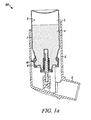
- Figure 1 shows a metered dose dispenser (100), in particular an inhaler, including an aerosol container (1) fitted with a metered dose valve (10) (shown in its resting position).
- metered dose dispenser 100
- inhaler including an aerosol container (1) fitted with a metered dose valve (10) (shown in its resting position).
- Aerosol containers for metered dose inhalers are typically made of aluminum or an aluminum alloy. Aerosol containers may be made of other materials, such as stainless steel, glass, plastic and ceramics.
- the valve is typically affixed onto the container via a cap or ferrule (11) (typically made of aluminum or an aluminum alloy) which is generally provided as part of the valve assembly.
- the illustrated valve is a commercial valve marketed under the trade designation SPRAYMISER by 3M Company, St. Paul, Minnesota, USA.
- the container/valve dispenser is typically provided with an actuator (5) including an appropriate patient port (6), such as a mouthpiece.
- an appropriate patient port e.g. smaller diameter tube, often sloping upwardly
- Actuators are generally made of a plastic, for example polypropylene or polyethylene.
- aerosol formulation may be filled into the container either by cold-filling (in which chilled formulation is filled into the container and subsequently the metered dose valve is fitted onto the container) or by pressure filling (in which the metered dose valve is fitted onto the container and then formulation is pressure filled through the valve into the container).
- An aerosol formulation used in a metered dose inhaler typically comprises a medicament or a combination of medicaments and liquefied propellant selected from the group consisting of HFA 134a, HFA 227 and mixtures thereof.
- Aerosol formulations may, as desired or needed, comprise other excipients, such as surfactant, a co-solvent (e.g. ethanol), CO 2 , or a particulate bulking agent.
- Medicament may be provided in particulate form (generally having a median size in the range of 1 to 10 microns) suspended in the liquefied propellant.
- medicament may be in solution (e.g. dissolved) in the formulation.
- a medicament may be a drug, vaccine, DNA fragment, hormone or other treatment.
- the amount of medicament would be determined by the required dose per puff and available valve sizes, which are typically 25, 50 or 63 microlitres, but may include 100 microlitres where particularly large doses are required.
- Suitable drugs include those for the treatment of respiratory disorders, e.g., bronchodilators, anti-inflammatories (e.g. corticosteroids), anti-allergics, anti-asthmatics, anti-histamines, and anti-cholinergic agents.
- Therapeutic proteins and peptides may also be employed for delivery by inhalation.
- Exemplary drugs which may be employed for delivery by inhalation include but are not limited to: albuterol, terbutaline, ipratropium, oxitropium, tiotropium, beclomethasone, flunisolide, budesonide, mometasone, ciclesonide, cromolyn sodium, nedocromil sodium, ketotifen, azelastine, ergotamine, cyclosporine, salmeterol, fluticasone, formoterol, procaterol, indacaterol, TA2005, omalizumab, zileuton, insulin, pentamidine, calcitonin, leuprolide, alpha-1-antitrypsin, interferons, triamcinolone, and pharmaceutically acceptable salts and esters thereof such as albuterol sulfate, formoterol fumarate, salmeterol xinaf
- Embodiments, described in detail below, in accordance with the present invention are particularly useful in regard to metered dose inhalers including a medicinal aerosol formulation that include low amounts of surfactant (0.005 wt % with respect to the formulation); or is substantially free (less than 0.0001 wt % with respect to drug) or free of a surfactant.
- embodiments described in detail below are particularly useful in metered dose inhalers including a medicinal aerosol formulation that contains low amounts of ethanol (less than 5 wt % with respect to the formulation), or is substantially free (less than 0.1 wt % with respect to the formulation) or free of ethanol.
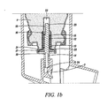
- the valve shown in Figure 1a better viewed in Figure 1b , includes a metering chamber (12), defined in part by an inner valve body (13), through which a valve stem (14) passes.
- the valve stem which is biased outwardly by a compression spring (15), is in sliding sealing engagement with an inner tank seal (16) and an outer diaphragm seal (17).
- the valve also includes a second valve body (20) in the form of a bottle emptier.
- valve body defining in part the metering chamber will be referred to as a "primary" valve body, while other types of valve body, e.g. defining a pre-metering region, a pre-metering chamber, a spring cage and/or a bottle emptier will be referred to as a "secondary" valve body.
- aerosol formulation (4) can pass from the formulation chamber into a pre-metering chamber (22) provided between the secondary valve body (20) and the primary valve body (13) through an annular space (21) between the flange (23) of the secondary valve body and the primary valve body.
- the valve stem (14) is pushed inwardly relative to the container from its resting position shown in Figures 1a and b , allowing formulation to pass from the metering chamber through a side hole (19) in the valve stem and through a stem outlet (24) to an actuator nozzle (7) then out to the patient.
- valve stem (14) When the valve stem (14) is released, formulation enters into the valve, in particular into the pre-metering chamber (22), through the annular space (21) and thence from the pre-metering chamber through a groove (18) in the valve stem past the tank seal (16) into the metering chamber (12).
- Figures 2 to 5 show other known metered dose valves used in pMDIs. Similar to the valve shown in Figure 1 , the valves of Figures 2 to 5 are typically fitted via a ferrule onto an aerosol container whereby a formulation chamber is defined by the inner walls of the container and the outer walls of the portion(s) of the valve located within the container. For the sake of ease in understanding and comparison, similar components of the respective valves are identified with like reference numbers in the Figures.
- FIG 2 shows a metered dose valve (10) of a type generally similar to that disclosed and described in US Patent 5,772,085 (incorporated herein by reference).
- the valve is shown in its resting position and includes a valve body (20) and a valve stem (14).
- the valve stem which is biased outwardly under the pressure of the aerosol formulation contained within the formulation container, is provided with an inner seal and an outer seal (16 and 17).
- the valve here is a release-to-fire type valve.
- valve stem (14) is first pushed upwards into the formulation chamber (not shown), so that the outer seal (17) passes inwardly beyond an outlet (25) provided in the external portion of the valve body and the inner seal (16) then passes inwardly and disengages from the inner walls of the valve body, thus bringing the metering chamber (12) up into the formulation chamber so that formulation can enter the metering chamber (referred to as the priming position of the valve) and then the valve stem is released moving outwardly so that the inner seal re-engages the valve body and the outer seal then passes outwardly beyond the outlet, bringing the metering chamber in communication with the outlet, so that formulation passes through the outlet to the patient.
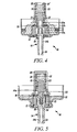
- FIG. 3 shows a metered dose valve (10) of the type generally similar to that disclosed and described in WO 2004/022142 (incorporated herein by reference).
- the valve is shown in its resting position and includes a secondary valve body (20) and a valve stem (14) that is biased outwardly by a compression spring (15).
- the valve is provided with an inner seal (16) and outer diaphragm seal (17), with the valve stem being in sliding sealing engagement with the diaphragm seal.
- the secondary valve body is in the form of a spring cage housing having three slots (21, two visible) providing communication between the formulation chamber (not shown) and a pre-metering chamber (22).
- This valve includes a transitory metering chamber formed upon actuation of the valve.
- a metering chamber (12, not visible) is formed between a lower surface (28) of a conical portion (27) of the valve stem (14) and an upper, sloping surface (31) of a primary valve body (13). Aerosol formulation passes around the shoulder (30) of the conical portion of the valve stem into the forming metering chamber and as the valve stem is further pushed in the upper surface (29) of the conical portion forms a face seal with the inner seal (16), thereby sealing off the metering chamber.
- valve stem As the valve stem is yet further displaced inwardly, formulation is allowed to pass from the metering chamber through side holes (19) in the valve stem and through a stem outlet (24) in the valve stem, and subsequently out to the patient typically via an actuator nozzle (7, not shown).
- Figure 4 shows a commercial metered dose valve supplied by Bespak, Bergen Way, King's Lynn, Norfolk, PE30 2JJ, UK under the trade designation BK357, in its resting position.
- the valve includes a secondary valve body (20) in the form of a spring cage with two slots (21) and an opening at the top (21') allowing communication between the formulation chamber (not shown) and a pre-metering chamber (22).
- the valve also includes a valve stem (14), made of two components (14a, 14b), which is biased outwardly by a compression spring (15) and passes through a metering chamber (12) defined in part by a primary valve body (13).
- the valve stem is in sliding sealing engagement with an inner seal (16) and an outer diaphragm seal (17). Aerosol formulation can pass from the pre-metering chamber (22) into the metering chamber (12) via side holes (33a, 33b) in the upper portion (14a) of the stem (14).
- valve stem (14) is pushed inwardly relative to the container, allowing a metered dose of formulation to pass from the metering chamber through a side hole (19) in the valve stem and through a stem outlet (24) and then typically through an actuator nozzle (7, not shown) out to the patient.
- FIG. 5 shows a commercial metered dose valve supplied by Valois SAS, Pharmaceutical Division, Route des Falaises, 27100 le Vaudreuil, France under the trade designation RCS, in its resting position.
- the valve includes a secondary valve body (20) in the form of a spring cage with three slots (21, two visible) allowing communication between the formulation chamber (not shown) and a pre-metering chamber (22).
- the valve also include a valve stem (14), made of two components (14a, 14b), which is biased outwardly by a compression spring (15) and passes through a metering chamber (12) defined in part by a primary valve body (13).
- the valve stem is in sliding sealing engagement with an inner seal (16) and an outer diaphragm seal (17).
- Aerosol formulation can pass from the pre-metering chamber (22) into the metering chamber through a side hole (33) and an internal channel (34) provided in the upper portion (14a) of the valve stem. Similar to the valve shown in Figure 1 , to actuate (fire) the valve, the valve stem (14) is pushed inwardly relative to the container, allowing formulation to pass from the metering chamber through a side hole (19) in the valve stem and through a stem outlet (24) and then typically through an actuator nozzle (7, not shown) out to the patient.
- the components of such valves are made of metal (e.g. stainless steel, aluminum or aluminum alloy) or plastic.
- metal e.g. stainless steel, aluminum or aluminum alloy
- compression springs are generally made of a metal, in particular stainless steel as the conventional material.
- Compression springs may also be made of aluminum or aluminum alloy.
- Valve stems and valve bodies are generally made of metal and/or plastic; as a metal conventionally stainless steel is used (other metals that may be used include aluminum, aluminum alloy and titanium) and as plastics conventionally polybutylene terephthalate (PBT) and/or acetal are used (other polymers that may be used include polyetheretherketones, nylon, other polyesters (such as tetrabutylene terephthalate), polycarbonates and polyethylene).
- a surface more favorably the entire surface, of a component or components of a medicinal inhalation device (e.g. aerosol containers, actuators, ferrules, valve bodies, valve stems or compression springs of metered dose inhalers or powder containers of dry powder inhalers) which is or will come in contact with a medicament or a medicinal formulation during storage or delivery from the medicinal inhalation device are treated according to methods described herein.
- a component or components of a medicinal inhalation device e.g. aerosol containers, actuators, ferrules, valve bodies, valve stems or compression springs of metered dose inhalers or powder containers of dry powder inhalers
- metered dose inhalers or powder containers of dry powder inhalers are treated according to methods described herein.
- the entire surface of the component including any surface or surfaces (if present) that do not or will not come in contact with a medicament or a medicinal formulation during storage or delivery from the device, are treated according to methods described herein.
- a component or components of a medicinal inhalation device which either come in contact with a movable component or are movable during storage or delivery from the medicinal inhalation device are treated according to methods described herein.
- components for metered dose inhalers include e.g. valve bodies, valve stems or compression springs of metered dose valves.
- a component of a medicinal inhalation device in accordance with the present invention or made according to methods in accordance with the present invention is a component of a metered dose inhaler.
- Said component may be selected from the group consisting of aerosol container, an actuator, a ferrule, a valve body (e.g. a primary and/or a secondary valve body), a valve stem and a compression spring.
- a component of a medicinal inhalation device in accordance with the present invention or made according to methods in accordance with the present invention is a component of a dry powder inhaler.
- Said component may be selected from the group consisting of a component that defines at least in part a powder container (e.g.
- a multidose reservoir container or single dose blister or capsule an component used to open a sealed powder container (e.g. piercer to open single dose blisters or capsules), a component that defines at least in part a deagglomeration chamber, a component of a deaglomeration system, a component that defines at least in part a flow channel, a dose-transporting component (e.g. a dosing rod, dosing wheel or dosing cylinder with a recess dimensioned to accommodate a single dose of powder trapped between said component and a housing in which it moves to transport the dose), a component that defines at least in part a mixing chamber, a component that defines at least in part an actuation chamber (e.g. a holding chamber where a dose is dispensed prior to inhalation), a mouthpiece and a nosepiece.
- a dose-transporting component e.g. a dosing rod, dosing wheel or dosing cylinder with a recess dimensioned to accommodate a single
- Embodiments in accordance with certain aspects of the present invention include forming a non-metal coating on at least a portion of a surface of a medicinal inhalation device or a component of a medicinal inhalation device (e.g. an aerosol container of a metered dose inhaler, a metered dose valve or a component thereof, or a powder container of a dry powder inhaler), said coating having at least one functional group, where the at least one functional group is capable of forming a covalent bond with the at least one functional group of the at least partially fluorinated compound.
- a non-metal coating on at least a portion of a surface of a medicinal inhalation device or a component of a medicinal inhalation device (e.g. an aerosol container of a metered dose inhaler, a metered dose valve or a component thereof, or a powder container of a dry powder inhaler), said coating having at least one functional group, where the at least one functional group is capable of forming a covalent bond with
- the at least one functional group of the non-metal coating desirably includes an active hydrogen.
- the at least one functional group is favorably a hydroxyl group (-OH), a thiol group (-SH), an amine group (-NH- or -NH 2 ), a carboxyl group (-COOH), an amide group (-CONH- or -CONH 2 ) or a mixture of such groups; more favorably a hydroxyl group, a carboxyl group or a mixture of such groups; and most favorably a hydroxyl group.
- forming a non-metal coating includes forming a coating comprising silicon, oxygen, and hydrogen, more favorably a non-metal coating comprising carbon, silicon, oxygen and hydrogen.
- Non-metal coatings described herein may be formed through a variety of know coating techniques. However it has been found that the application of such coatings through plasma deposition is desirable, more desirably through plasma deposition under conditions of ion bombardment.
- non-metal coatings may be desirably provided by plasma polymerization of an appropriate monomer or monomers, optionally in the presence of an appropriate assist gas, such as oxygen, using conventional conditions used in e.g. microwave, inductively coupled, DC and RF (radio frequency) plasma deposition, where polymerized species formed in the plasma deposit on the substrate to provide a polymer coating on the surface(s) of the substrate.
- an appropriate assist gas such as oxygen
- non-metal coatings are provided by plasma deposition under conditions of ion bombardment.
- plasma deposition is carried out in such a way that an ion sheath is formed upon generation of the plasma (plasma formed from an appropriate source compound or compounds, optionally in the presence of an appropriate assist gas, such as oxygen) and where the substrate, whose surface is or surfaces are to be coated, is positioned within the plasma chamber so that during plasma deposition the substrate is within the ion sheath.
- RF-plasma deposition this can be generally accomplished through the use of a RF-powered electrode and locating the substrate to be coated in proximity to the RF-powered electrode.
- RF-plasma deposition this can be accomplished by providing the microwave or inductively coupled plasma system, respectively, with an electrode, biasing (generally negatively biasing) this electrode and locating the substrate in proximity to said biased electrode.
- biasing generally negatively biasing
- DC plasma deposition this can be accomplished by locating the substrate in proximity to the cathode or negatively biased electrode (e.g.
- amorphous covalent systems in particular such systems comprising silicon, oxygen and hydrogen, and more particularly further comprising carbon, show excellent adhesion (through e.g. covalent bonding) to many substrate materials, including metals, polymers, glass and ceramics.
- covalent amorphous systems provide "sharp" coatings e.g.
- covalent amorphous systems in particular such systems comprising silicon, oxygen and hydrogen, and more particularly further comprising carbon
- covalent amorphous systems are desirable in that they are typically transparent or translucent.
- amorphous covalent systems show advantageously high atomic packing densities, typically in a range from about 0.20 to about 0.28 (in particular from about 0.22 to about 026) gram atom number density in units of gram atoms per cubic centimeter.
- Polymeric coatings e.g. plasma polymer coatings
- Such high atomic packing densities allow the provision of coatings having a minimum of porosity, excellent resistance to diffusion to liquid or gaseous materials, and superb, "diamond-like" hardness.
- Micro-hardness of such coatings is generally, favorably at least 1 GPa, more favorably at least 2 GPa.
- Such coatings also advantageously have a low coefficient of friction/surface energy.
- Such coatings further comprising carbon generally termed here as “diamond-like glass” show desirous flexibility together with diamond-like hardness, allowing for desirable long-term durability, in particular advantageous long-term durability of said coatings on movable components (e.g. compression springs) or on components coming into contact with other components due to movement (e.g.
- Micro-elastic-modulus of such coatings is generally, favorably at least 11 GPa, more favorably at least 13 GPa. Due to the desirable properties of the aforesaid described coatings, they are particularly advantageous for use as coatings in medicinal inhalation devices or components thereof either alone or as a coating onto which a composition comprising an at least partially fluorinated compound comprising at least one functional group is applied. In regard to the latter, again due to desirable high atomic packing densities such non-metal coatings allow for the provision of a dense distribution and high number of functional groups, such as functional groups having an active hydrogen (e.g. hydroxyl groups (-OH) and/or carboxyl groups (-COOH), in particular hydroxyl groups) for subsequent bonding upon application of said composition comprising at least partially fluorinated compound comprising an at least one functional group.
- functional groups having an active hydrogen e.g. hydroxyl groups (-OH) and/or carboxyl groups (-COOH)
- Coatings provided by plasma deposition under conditions of ion bombardment and comprising silicon, oxygen and hydrogen desirably have a silicon to oxygen ratio less than two.
- Diamond-like glass coatings favorably contain on a hydrogen free basis at least about 20 atomic percent carbon and at least about 30 atomic percent of silicon + oxygen, more favorably at least about 25 atomic percent carbon, about 15 to about 50 atomic percent of silicon and about 15 to about 50 atomic percent oxygen, even more favorably about 30 to about 60 atomic percent carbon, about 20 to about 45 atomic percent of silicon and about 20 to about 45 atomic percent oxygen, yet even more favorably about 30 to about 50 atomic percent carbon, about 25 to about 35 atomic percent of silicon and about 25 to about 45 atomic percent oxygen, and most favorably about 30 to about 36 atomic percent carbon, about 26 to about 32 atomic percent of silicon and about 35 to about 41 atomic percent oxygen.
- Diamond-like glass coatings desirably have a silicon to oxygen ratio less than two.
- “Hydrogen free basis” refers to the atomic composition of a material as established by a method such as Electron Spectroscopy for Chemical Analysis (ESCA) which does not detect hydrogen even if large amounts are present in the coating.
- ESA Electron Spectroscopy for Chemical Analysis
- the combination of fairly high amounts of silicon and oxygen with significant amounts carbon makes diamond-like glass coatings flexible (unlike glass or amorphous carbon coatings such as diamond-like carbon coatings). Also due to said combination diamond-like glass coatings have relatively low intrinsic stress and thus excellent long-term adhesion and durability (unlike diamond-like carbon coatings which have a tendency to flake off due to relatively high intrinsic stress within the coating).
- diamond like glass coatings are particularly advantageous as coatings on a surface or surfaces of medicinal inhalation device components which undergo movement in itself (e.g. a compression spring of a metered dose valve) or movement in conjunction with or relative to other components (e.g. a valve stem of a metered dose valve).
- a compression spring of a metered dose valve e.g. a compression spring of a metered dose valve
- other components e.g. a valve stem of a metered dose valve.
- Diamond-like glass coatings as well as methods of making diamond-like glass and apparatus for depositing diamond-like glass are described in U.S. Patent No. 6,696,157 (David et al ), the contents of which is incorporated here in its entirety.
- plasma deposition under conditions of ion bombardment is distinct from plasma polymerization.
- plasma deposition is carried out in such a manner that no ion sheath is formed (e.g. using conventional microwave or inductively coupled plasma systems) or the substrate to be coated with the polymer is positioned outside of any ion sheath, if at all formed.
- the substrate is located in proximity to the grounded electrode or placed at a floating potential (i.e. electrically isolated and located outside of any ion sheath formed during RF-plasma deposition).
- plasma deposition as used herein, unless otherwise specified, will be understood to include inter alia plasma polymerization as well as plasma deposition under conditions of ion bombardment, where in each case plasma deposition under conditions of ion bombardment is understood to be preferred.
- plasma deposited as used herein, unless otherwise specified, will be understood to include inter alia plasma polymerized as well as plasma deposited under ion bombardment, where in each case plasma deposited under ion bombardment is understood to be preferred.
- Forming a non-metal coating as described herein by plasma deposition can be carried out in a suitable reaction chamber having a capacitively-coupled system with at least one electrode powered by an RF (radio frequency) source and at least one grounded electrode, such as those described in U.S. Patent Nos. 6,696,157 (David et al. ) and 6,878,419 (David et al. ).
- Figure 6 illustrates an exemplary apparatus (200) suitable for the plasma deposition, in particular plasma deposition under conditions of ion bombardment, showing a grounded chamber (120) (also acting here as a grounded electrode) from which air is removed by a pumping stack (not shown).
- Substrate (140) typically a medicinal inhalation device component per se or alternatively a work-piece from which such a component may be subsequently formed or worked, is favorably positioned proximate RF-powered electrode (160). Electrode (160) is insulated from chamber (120) by a polytetrafluoroethylene support (180).
- Figure 7 illustrates another exemplary apparatus (200) for the plasma deposition, in particular plasma deposition under conditions of ion bombardment, where a substrate or (as shown in Figure 7 ) a plurality of substrates (140) (again such substrate(s) being typically medicinal inhalation device component(s) per se or alternatively a work-piece(s) from which such a component may be subsequently formed or worked) are tumbled during deposition, such tumbling favorably allowing for uniform deposition on the surfaces of the substrate(s).
- the chamber (120) is a tube, in particular a quartz tube, the ends of which are sealed with flanges (not shown), in particular aluminum flanges.
- Each end flange is typically provided with a port, a port at one end being connected to a pumping stack (not shown) and a port at the other end being connected to gas supply system (not shown).
- the ports together with the connecting-system are favorably configured and arranged to allow for rotation of the tube and thus the chamber during plasma deposition. Air is typically removed from the chamber after loading by the pumping stack through the exit pumping port, and the gas or gases to form the plasma are generally injected through the inlet gas port at the other end, said gas or gases passing then through the chamber towards the exit pumping port.
- RF-powdered electrode (160) is advantageously configured as an arc conforming to the curvature of the tube and is positioned just underneath the tube but separated from the tube by a narrow gap.
- the chamber and RF-powered electrode are favorably housed inside with a housing (130), in particular a housing made of a perforated metal, that serves as a grounded counter electrode. Similar to the system shown in Figure 6 , power is typically provided by a RF power supply (170) through a matching network (175).
- the chamber (120) is advantageously rotated so the substrate(s) (140) to be coated tumble; tumbling can be desirably facilitated through the inclusion of baffles (125) within the tube.
- the substrate(s) to be coated will be found with the lower portion of the tube, and thus favorably positioned in proximity of the RF-powered electrode (160) so that the substrate(s) will be located within the ion sheath.
- oxygen plasma Before plasma deposition, it is desirable to expose the substrate to an oxygen plasma or alternatively an argon plasma, more desirably oxygen plasma. It is most desirable to expose the substrate to an oxygen plasma under conditions of ion bombardment (i.e. generating an ion sheath and having the substrate located within the ion sheath during said oxygen plasma treatment). Typically for this pre-treatment, pressures in the chamber are maintained between 1.3 Pa (10 mTorr) and 27 Pa (200 mTorr). Plasma is generated with RF power levels of between 500 W and 3000 W.
- a solvent washing step with an organic solvent such as acetone or ethanol may also be included prior to the exposure to an oxygen or argon plasma as described above.
- the substrate is located in proximity of the RF-powered electrode (as schematically depicted in Figure 6 ) in the chamber so that the substrate will be within the ion sheath.
- the substrate to be coated would be placed in the chamber at a floating potential with the substrate being located such that it would not be within the ion sheath.
- an alternative system may be used which is provided with an additional grounded electrode (rather than having the chamber act as the grounded electrode) and the substrate to be coated would be then located in the proximity of the grounded electrode.
- the chamber is typically evacuated to the extent necessary to remove air and any impurities. This may be accomplished by vacuum pumps at a pumping stack connected to the chamber.
- a source gas is introduced into the chamber at a desired flow rate, which depends on the size of the reactor, the surface area of the electrodes, and the surface area of the substrate.
- the gas is typically and desirably oxygen.
- the gas further comprises an appropriate organosilicon and/or a silicon hydride compound, and the flow rates are sufficient to establish a suitable pressure at which to carry out plasma deposition, typically 0.13 Pa to 130 Pa (0.001 Torr to 1.0 Torr).
- a suitable pressure at which to carry out plasma deposition typically 0.13 Pa to 130 Pa (0.001 Torr to 1.0 Torr).
- the flow rates are typically from about 50 to about 500 standard cubic centimeters per minute (sccm).
- the gas remains in the vapor form.
- An RF electric field is applied to the powered electrode, ionizing the gas and establishing a plasma.
- energy is coupled into the plasma through electrons.
- the plasma acts as the charge carrier between the electrodes.
- the plasma can fill the entire reaction chamber and is typically visible as a colored cloud.
- the plasma also forms an ion sheath proximate at least to the RF-powered electrode.
- the ion sheath typically appears as a darker area around the electrode.
- the depth of the ion sheath normally ranges from about 1 mm to about 50 mm and depends on factors such as the type and concentration of gas used, pressure in the chamber, the spacing between the electrodes, and relative size of the electrodes. For example, reduced pressures will increase the size of the ion sheath. When the electrodes are different sizes, a larger, stronger ion sheath will form around the smaller electrode. Generally, the larger the difference in electrode size, the larger the difference in the size of the ion sheaths, and increasing the voltage across the ion sheath will increase ion bombardment energy.
- ions accelerating toward the electrode bombard the species being deposited from the plasma onto the substrate and thus the substrate is exposed to the ion bombarded species being deposited from the plasma.
- the resulting reactive species within the plasma react on the surface of the substrate, forming a coating, the composition of which is controlled by the composition of the gas being ionized in the plasma.
- the species forming the coating are advantageously attached to the surface of the substrate by covalent bonds, and therefore the coating is advantageously covalently bonded to the substrate.
- plasma deposition comprises ionizing a gas comprising at least one of an organosilicon or a silicon hydride compound.
- a gas comprising at least one of an organosilicon or a silicon hydride compound.
- the silicon of the at least one of an organosilicon or a silicon hydride compound is present in an amount of at least about 5 atomic percent of the gas mixture.
- a reactive gas such as oxygen
- an inert gas such as argon
- the gas desirably comprise an organosilicon.
- the organosilicon comprises at least one of trimethylsilane, triethylsilane, trimethoxysilane, triethoxysilane, tetramethylsilane, tetraethylsilane, tetramethoxysilane, tetraethoxysilane, hexamethylcyclotrisiloxane, tetramethylcyclotetrasiloxane, tetraethylcyclotetrasiloxane, octamethylcyclotetrasiloxane, hexamethyldisiloxane, and bistrimethylsilylmethane.
- the organosilicon comprises at least one of trimethylsilane, triethylsilane, tetramethylsilane, tetraethylsilane, and bistrimethylsilylmethane; and most particularly the organosilicon comprises tetramethylsilane.
- the gas may comprise a silicon hydride.
- the silicon hydride may comprise SiH 4 (silicon tetrahydride) and/or Si 2 H 6 (disilane), in particular SiH 4 (silicon tetrahydride).
- the gas further comprises oxygen.
- the gas may further comprise an additional gas or gases. Each additional gas can be added separately or in combination with each other.
- the gas may further comprise argon and/or hydrogen, in particular for plasma deposition under ion bombardment conditions.
- the application of argon normally is not incorporated into the deposited coating
- the application of hydrogen promotes the formation of high packing density as well as provides an additional source of hydrogen.
- the gas may further comprise ammonia and/or nitrogen.
- ammonia and nitrogen in which a composition comprising an at least partially fluorinated compound comprising at least one silane group will be applied, it is desirable not to use ammonia and nitrogen gas, nor a sulfur containing gas.
- the non-metal coating as described herein is substantially free or free of amine groups and substantially free or free of amido groups as well as substantially free or free of thiol groups so as to minimize or avoid formation of silicon-nitrogen or silicon-sulfur bonds, said bonds having been determined to be undesirable in terms of durability and/or robustness of the coating system over the life of medicinal inhalation devices.
- the non-metal coating is advantageously substantially free of nitrogen (e.g. at most about 5 atomic percent of nitrogen (on a hydrogen free basis)), in particular free of nitrogen.
- the non-metal coating is advantageously substantially free of sulfur (e.g. at most about 1 atomic percent of sulfur (on a hydrogen free basis)), in particular free of sulfur.
- the gas may further comprise a source of fluorine e.g. carbon tetrafluoride.
- fluorine e.g. carbon tetrafluoride
- the inclusion of fluorine has been determined to be generally undesirable in terms of structural integrity of non-metal coating (in particular adhesion of the non-metal coating to the substrate surface as well as overall durability of the non-metal coating).
- the non-metal coating is advantageously substantially free of fluorine (e.g. at most about 1 atomic percent of fluorine (on a hydrogen free basis)), in particular free of fluorine.
- Plasma deposition of the non-metal coating typically occurs at a rate ranging from about 1 to about 100 nm/second.
- the rate will depend on conditions including pressure, power, concentration of gas, types of gases, relative size of the electrodes, and so on. In general, the deposition rate increases with increasing power, pressure, and concentration of gas, although the rate can approach an upper limit.
- Desirably plasma deposition of the non-metal coating is carried out for a period of time such that the coating has a thickness in the range from about 5 nm to about 5000 nm. Generally within this range it is favorable to provide coatings having a thickness of at least about 10 nm, more favorably at least about 50 nm, and most favorably at least about 100 nm. Also within the aforesaid ranges generally it is favorable to provide coatings having a thickness less than about 1000 nm, more favorably at most about 950 nm, even more favorably at most about 800 nm, yet even more favorably at most about 675 nm and most favorably at most about 550 nm.
- the surface of the non-metal coating is favorably exposed to an oxygen plasma, more favorably exposed to an oxygen plasma under ion bombardment conditions (for example in order to form or to form additional silanol groups on the surface of the non-metal coating).
- a treatment is particularly advantageous for embodiments in which a composition comprising an at least partially fluorinated compound comprising at least one functional group will be applied.
- pressures in the plasma chamber are typically maintained between 1.3 Pa (10 mTorr) and 27 Pa (200 mTorr), and oxygen plasma is generated with RF power levels of between about 50 W and about 3000 W.
- Embodiments according to certain aspects of the present invention include applying to at least a portion of a surface of the non-metal coating a composition comprising an at least partially fluorinated compound comprising at least one functional group, and allowing at least one functional group of the at least partially fluorinated compound to react with at least one functional group of the non-metal coating to form a covalent bond.
- a composition comprising an at least partially fluorinated compound comprising at least one functional group, and allowing at least one functional group of the at least partially fluorinated compound to react with at least one functional group of the non-metal coating to form a covalent bond.
- said composition is applied to the entire surface of the non-metal coating.
- the non-metal coating prior to applying the composition comprising an at least partially fluorinated compound comprising at least one functional group, is desirably exposed to an oxygen plasma, more desirably exposed to an oxygen plasma under ion bombardment conditions.
- the non-metal coating may be favorably exposed to a corona treatment prior to applying the composition comprising the at least partially fluorinated compound comprising at least one functional group.
- the at least partially fluorinated compound includes a polyfluoropolyether segment, preferably a perfluorinated polyfluoropolyether segment, for enhanced surface properties as well as enhanced coating efficiency and structural integrity.
- a polyfluoropolyether segment including perfluorinated repeating units including short chains of carbon, where desirably the number of carbon atoms in sequence is at most 6, more desirably at most 4, even more desirably at most 3, and most desirably at most 2, facilitates durability/flexibility of the applied fluorine-containing coating as well as minimizing a potential of bioaccumulation of perfluorinated moieties.
- the at least one functional group of the at least partially fluorinated compound includes a hydrolysable group (e.g. hydrolysable in the presence of water, optionally under acidic or basic conditions producing groups capable of undergoing a condensation reaction (for example silanol groups)).
- a hydrolysable group e.g. hydrolysable in the presence of water, optionally under acidic or basic conditions producing groups capable of undergoing a condensation reaction (for example silanol groups)).
- the at least one functional group of the at least partially fluorinated compound is a silane group.
- the silane group includes at least one hydrolysable group, more favorably at least two hydrolysable groups, and most favorably three hydrolysable groups.
- the hydrolysable groups may be the same or different.
- a hydrolysable group is a group selected from the group consisting of hydrogen, halogen, alkoxy, acyloxy, aryloxy, and polyalkyleneoxy, more desirably a group selected from the group consisting of alkoxy, acyloxy, aryloxy, and polyalkyleneoxy, even more desirably a group selected from the group consisting of alkoxy, acyloxy and aryloxy, and most desirably an alkoxy group (e.g. OR' wherein each R' is independently a C 1-6 alkyl, in particular a C 1-4 alkyl).
- the at least partially fluorinated compound comprising at least one functional group is a polyfluoropolyether silane, more desirably a multifunctional polyfluoropolyether silane, and most desirably a difunctional polyfluoropolyethersilane.
- multifunctional polyfluoropolyether silane as used herein is generally understood to mean a multivalent polyfluoropolyether segment functionalized with a multiple of functional silane groups
- difunctional polyfluoropolyether silane as used herein is generally understood to mean a divalent polyfluoropolyether segment functionalized with a multiple of functional silane groups (in particular two to four functional silane groups, more particular two functional silane groups).
- polyfluoropolyether segment(s) is (are) not linked to silane group(s) via a functionality that includes a nitrogen-silicon bond or sulfur-silicon bond.
- polyfluoropolyether segment(s) is (are) linked to silane group(s) via a functionality that include a carbon-silicon bond, more particularly via a -C(R) 2 -Si functionality where R is independently hydrogen or a C 1-4 alkyl group (preferably hydrogen), and most particular, via a -(C(R) 2 ) k -C(R) 2 -Si functionality where k is at least 2 (preferably 2 to about 25, more preferably 2 to about 15, most preferably 2 to about 10).
- R is independently hydrogen or a C 1-4 alkyl group (preferably hydrogen)
- k is at least 2 (preferably 2 to about 25, more preferably 2 to about 15, most preferably 2 to about 10).
- the at least partially fluorinated compound comprising at least one silane group is a polyfluoropolyether silane of the Formula Ia: R f [Q-[C(R) 2 -Si(Y) 3-x (R 1a ) x ] y ] z Ia wherein:
- polyfluoropolyether silanes in accordance with Formula Ia favorably allows the provision of medicinal inhalation devices or components thereof comprising a non-metal coating on at least a portion of surface of the device or component, as applicable, and a polyfluoropolyether-containing coating bonded to the non-metal coating, wherein the polyfluoropolyether-containing coating comprises polyfluoropolyether silane entities of the following Formula Ib: R f [Q-[C(R) 2 -Si(O-) 3-x (R 1a ) x ] y ] z Ib which shares at least one covalent bond with non-metal coating; and wherein:
- the at least one covalent bond shared with the non-metal coating is a bond to an oxygen atom in Si(O-) 3-x .
- such polyfluoropolyether-containing coatings are typically transparent or translucent.
- the monovalent or multivalent polyfluoropolyether segment, R f includes linear, branched, and/or cyclic structures, that may be saturated or unsaturated, and includes two or more in-chain oxygen atoms.
- R f is preferably a perfluorinated group (i.e., all C-H bonds are replaced by C-F bonds).
- hydrogen atoms may be present instead of fluorine atoms provided that not more than one atom of hydrogen is present for every two carbon atoms.
- R f includes at least one perfluoromethyl group.
- the monovalent or multivalent polyfluoropolyether segment, R f comprises perfluorinated repeating units selected from the group consisting of -(C n F 2n )-, - (C n F 2n O)-, -(CF(Z))-, -(CF(Z)O)-, -(CF(Z)C n F 2n O)-, -(C n F 2n CF(Z)O)-, -(CF 2 CF(Z)O)-, and combinations thereof; wherein n is an integer from 1 to 6; Z is a perfluoroalkyl group, an oxygen-containing perfluoroalkyl group, a perfluoroalkoxy group, or an oxygen-substituted perfluoroalkoxy group, each of which can be linear, branched, or cyclic, and have 1 to 5 carbon atoms and up to 4 oxygen atoms when oxygen-containing or oxygen-substituted.
- the total number of carbon atoms in sequence per unit is at most 6 (more desirably at most 4, and most desirably at most 3). Being oligomeric or polymeric in nature, these compounds exist as mixtures and are suitable for use as such.
- the perfluorinated repeating units may be arranged randomly, in blocks, or in an alternating sequence.
- the polyfluoropolyether segment comprises perfluorinated repeating units selected from the group consisting of -(C n F 2n O)-, -(CF(Z)O)-, -(CF(Z)C n F 2n O)-, -(C n F 2n CF(Z)O)-, -(CF 2 CF(Z)O)-, and combinations thereof; and more favorably perfluorinated repeating units selected from the group consisting of -(C n F 2n O)-, -(CF(Z)O)-, and combinations thereof.
- n is an integer from 1 to 4; or 1 to 3; or 1 or 2.
- Z is a -CF 3 group.
- R f is monovalent, and z is 1.
- R f is terminated with a group selected from the group consisting of C n F 2n+1 -, C n F 2n+1 O-, and X'C n F 2n O- wherein X' is a hydrogen.
- the terminal group is C n F 2n+1 - or C n F 2n+1 O- wherein n is an integer from 1 to 6 or 1 to 3.
- the approximate average structure of R f is C 3 F 7 O(CF(CF 3 )CF 2 O) p CF(CF 3 )-, CF 3 O(C 2 F 4 O) P CF 2 -, C 3 F 7 O(CF(CF 3 )CF 2 O) p CF 2 CF 2 -,C 3 F 7 O(CF 2 CF 2 CF 2 O) p CF 2 CF 2 -, or C 3 F 7 O(CF 2 CF 2 CF 2 O) p CF(CF 3 )-, or CF 3 O(CF 2 CF(CF 3 )O) p (CF 2 O)X- (wherein X is CF 2 -, C 2 F 4 -, C 3 F 6 -, C 4 F 8 -) wherein the average value of p is 3 to 50.
- R f is preferably multivalent and z is 2, 3 or 4, more preferably R f is divalent, and z is 2.
- the approximate average structure of R f is selected from the group consisting of -CF 2 O(CF 2 O) m (C 2 F 4 O) p CF 2 -, -CF 2 O(C 2 F 4 O) p CF 2 -, -CF(CF 3 )O(CF(CF 3 )CF 2 O) p CF(CF 3 )-, -(CF 2 ) 3 O(C 4 F 8 O) p (CF 2 ) 3 -, -CF(CF 3 )-(OCF 2 CF(CF 3 )) p O-C t F 2t -O(CF(CF 3 )CF 2 O) p CF(CF 3 )- (wherein t is 2 to 4), and wherein m is 1 to 50, and p is 3 to 40.
- R f is selected from the group consisting of -CF 2 O(CF 2 O) m (C 2 F 4 O) p CF 2 -, -CF 2 O(C 2 F 4 O) p CF 2 -, and -CF(CF 3 )-(OCF 2 CF(CF 3 )) p O-(C t F 2t )-O(CF(CF 3 )CF 2 O) p CF(CF 3 )-, and wherein t is 2, 3 or 4, and the average value of m+p or p+p or p is from about 4 to about 24.
- polyfluoropolyether silanes such as those described above, also typically include a distribution of oligomers and/or polymers, so p and/or m may be non-integral and where the number is the approximate average is over this distribution.
- the organic divalent or trivalent linking group, Q can include linear, branched, or cyclic structures that may be saturated or unsaturated.
- the organic divalent or trivalent linking group, Q optionally contains one or more heteroatoms selected from the group consisting of sulfur, oxygen, and nitrogen, and/or optionally contains one or more functional groups selected from the group consisting of esters, amides, sulfonamides, carbonyl, carbonates, ureylenes, and carbamates.
- Q favorably includes a segment with not less than 2 carbon atoms, said segment of Q being directly bonded to the -C(R) 2 -group of the silane-containing moiety (i.e.
- Q includes not more than about 25 carbon atoms.
- Q is preferably substantially stable against hydrolysis and other chemical transformations, such as nucleophilic attack.
- the Q groups can be the same or different.
- Q includes organic linking groups such as -C(O)N(R)-(CH 2 ) k -, -S(O) 2 N(R)-(CH 2 ) k -, -(CH 2 ) k -, -CH 2 O-(CH 2 ) k -, -C(O)S-(CH 2 ) k -, -CH 2 OC(O)N(R)-(CH 2 ) k -, and wherein R is hydrogen or C 1-4 alkyl, and k is 2 to about 25. For certain of these embodiments, k is 2 to about 15 or 2 to about 10.
- Q is a divalent linking group, and y is 1.
- Q is favorably a saturated or unsaturated hydrocarbon group including 1 to about 15 carbon atoms and optionally containing 1 to 4 heteroatoms and/or 1 to 4 functional groups.
- Q is a linear hydrocarbon containing 1 to about 10 carbon atoms, optionally containing 1 to 4 heteroatoms and/or 1 to 4 functional groups.
- Q contains one functional group.
- Q is preferably -C(O)N(R)(CH 2 ) 2 -, -OC(O)N(R)(CH 2 ) 2 -, -CH 2 O(CH 2 ) 2 -, or -CH 2 -OC(O)N(R)-(CH 2 ) 2 -, wherein R is hydrogen or C 1-4 alkyl.
- R is hydrogen
- the hydrolyzable groups, Y, of Formula Ia may be the same or different and are capable of hydrolyzing, for example, in the presence of water, optionally under acidic or basic conditions, producing groups capable of undergoing a condensation reaction, for example silanol groups.
- each Y of Formula Ia is independently a group selected from the group consisting of hydrogen, halogen, alkoxy, acyloxy, aryloxy, and polyalkyleneoxy, more desirably each Y is independently a group selected from the group consisting of alkoxy, acyloxy, aryloxy, and polyalkyleneoxy, even more desirably each Y is independently a group selected from the group consisting of alkoxy, acyloxy and aryloxy, and most desirably each Y is independently an alkoxy group.
- x is 0.
- R f is -CF 2 O(CF 2 O) m (C 2 F 4 O) p CF 2 - and Q-C(R) 2 -Si(Y) 3-x (R 1a ) x is C(O)NH(CH 2 ) 3 Si(OR') 3 wherein R' is methyl or ethyl.
- R f is -CF 2 O(CF 2 O) m (C 2 F 4 O) p CF 2 - and Q-C(R) 2 -Si(O-) 3 - x (R 1a ) x is C(O)NH(CH 2 ) 3 Si(O-) 3 .
- m and p are each about 9 to 12.
- the compounds of Formula Ia described above can be synthesized using standard techniques. For example, commercially available or readily synthesized perfluoropolyether esters (or functional derivatives thereof) can be combined with a functionalized alkoxysilane, such as a 3-aminopropylalkoxysilane, according to U.S. Patent No. 3,810,874 (Mitsch et al. ).
- the weight average molecular weight of the polyfluoropolyether segment is about 1000 or higher, more desirably about 1800 or higher. Higher weight average molecular weights further facilitate durability as well as minimizing a potential of bioaccumulation. Generally for ease in use and application, the weight average molecular weight of the polyfluoropolyether segment is desirably about 6000 at most and more desirably about 4000 at most.
- Polyfluoropolyether silanes typically include a distribution of oligomers and/or polymers. Desirably for facilitation of structural integrity of polyfluoropolyether-containing coating as well as minimization of a potential of bioaccumulation the amount of polyfluoropolyether silane (in such a distribution) having a polyfluoropolyether segment having a weight average molecular weight less than 750 is not more than 10% by weight (more desirably not more than 5 % by weight, and even more desirably not more 1% by weight and most desirable 0%) of total amount of polyfluoropolyether silane in said distribution.
- the composition comprising an at least partially fluorinated compound comprising at least one functional group further includes an organic solvent.
- the polyfluoropolyether silane is desirably applied as a composition comprising the polyfluoropolyether silane and an organic solvent.
- the organic solvent or blend of organic solvents used typically is capable of dissolving at least about 0.01 percent by weight of the polyfluoropolyether silaine, in particular one or more silanes of the Formula Ia. It is desirable that the solvent or mixture of solvents have a solubility for water of at least about 0.1 percent by weight, and for certain of these embodiments, a solubility for acid of at least about 0.01 percent by weight.
- Suitable organic solvents, or mixtures of solvents can be selected from aliphatic alcohols, such as methanol, ethanol, and isopropanol; ketones such as acetone and methyl ethyl ketone; esters such as ethyl acetate and methyl formate; ethers such as diethyl ether, diisopropyl ether, methyl t-butyl ether and dipropyleneglycol monomethylether (DPM); hydrocarbon solvents such as alkanes, for example, heptane, decane, and paraffinic solvents; fluorinated hydrocarbons such as perfluorohexane and perfluorooctane; partially fluorinated hydrocarbons, such as pentafluorobutane; hydrofluoroethers such as methyl perfluorobutyl ether and ethyl perfluorobutyl ether.
- aliphatic alcohols such as methanol, ethanol
- the organic solvent is a fluorinated solvent, which includes fluorinated hydrocarbons, partially fluorinated hydrocarbons, and hydrofluoroethers.
- the fluorinated solvent is a hydrofluoroether.
- the hydrofluoroether is methyl perfluorobutyl ether.
- the organic solvent is a lower alcohol.
- the lower alcohol is selected from the group consisting of methanol, ethanol, isopropanol, and mixtures thereof.
- the lower alcohol is ethanol.
- the composition favorably further comprises an acid.
- the acid is selected from the group consisting of acetic acid, citric acid, formic acid, triflic acid, perfluorobutyric acid, sulfuric acid, and hydrochloric acid.
- the acid is hydrochloric acid.
- composition comprising an at least partially fluorinated compound comprising at least one functional group may favorably further comprise a non-fluorinated cross-linking agent that is capable of engaging in a cross-linking reaction.
- a cross-linking agent comprises one or more non-fluorinated compounds, each compound having at least two hydrolysable groups.
- a cross-linking agent comprises one or more non-fluorinated compounds of silicon having at least two hydrolysable groups per molecule.
- the hydrolysable groups are directly bonded to the silicon in accordance to Formula II: Si(Y 2 ) 4-g (R 5 ) g II where R 5 represents a non-hydrolysable group; Y 2 represents a hydrolysable group; and g is 0, 1 or 2.
- the non-hydrolysable group R 5 is generally not capable of hydrolyzing under the conditions used during application of the composition comprising the at least partially compound comprising at least one functional group.
- the non-hydrolysable group R 5 may be independently selected from a hydrocarbon group. If g is 2, the non-hydrolysable groups may the same or different. Preferably g is 0 or 1, more preferably g is 0.
- the hydrolysable groups Y 2 may be the same or different and are generally capable of hydrolyzing under appropriate conditions, for example under acidic or basic aqueous conditions, such that the cross-linking agent can undergo condensation reactions. Preferably, the hydrolysable groups upon hydrolysis yield groups, such as silanol groups capable of undergoing condensation reactions. Typical and preferred examples of hydrolysable groups include those as described with respect to Formula Ia.
- Y 2 is an alkoxy, -OR 6 , more preferably an alkoxy where R 6 is a C 1-4 alkyl.
- Non-fluorinated silicon compounds for use in a cross-linking agent include tetramethoxysilane, tetraethoxysilane, tetrapropoxysilane, tetrabutoxysilane, methyl triethoxysilane, dimethyldiethoxysilane, octadecyltriethoxy-silane, 3-glycidoxypropyltriethoxysilane, 3-aminopropyltrimethoxysilane, 3-aminopropyl-triethoxysilane, 3-trimethoxysilylpropylmethacrylate and mixtures thereof.
- the cross-linking agent comprises C 1 -C 4 tetra-alkoxy derivatives of silicon, more preferably the cross-linking agent comprises tetraethoxysilane.
- the amounts by weight of the at least partially fluorinated compound to the non-fluorinated cross-linking agent can change from about 10: 1 to about 1:100, preferably from about 1:1 to about 1:50 and most preferably from about 1:2 to about 1:20.
- compositions including a hydrolysable group may further comprise water.
- composition comprising an at least partially fluorinated compound comprising at least one functional group in particular one silane group
- the composition comprising an at least partially fluorinated compound comprising at least one functional group in any one of its above described embodiments, is applied by dipping at least a portion of the substrate upon which the non-metal coating has been formed in said composition.
- the composition comprising the at least partially fluorinated compound comprising at least one functional group is applied by spraying at least a portion of the substrate upon which the non-metal coating has been formed with said composition.
- the composition comprises an at least partially fluorinated compound comprising at least one silane group (in particular a polyfluoropolyether silane or more particularly any one of the embodiments of Formula Ia) and the non-metal coating comprises silicon, oxygen, and hydrogen, for example, with -SiOH groups
- a extremely durable coating is formed through the formation of covalent bonds, including bonds in Si-O-Si groups.
- sufficient water should be present to cause hydrolysis of the hydrolyzable groups described above so that condensation to form Si-O-Si groups takes place, and thereby curing takes place.
- the water can be present either in the treating composition or adsorbed to the substrate surface, for example.
- sufficient water is present for the preparation of a durable coating if the application is carried out at room temperature in an atmosphere containing water, for example, an atmosphere having a relative humidity of about 30% to about 80%.
- Application is typically carried out by contacting the substrate with the treating composition, generally at room temperature (typically about 20°C to about 25°C).
- treating composition can be applied to a substrate that is pre-heated at a temperature of for example between 60°Cand 150°C.
- the treated substrate can be dried and cured at ambient temperature or (preferably) at elevated temperatures (e.g. at 40°C to 300°C), and for a time sufficient to dry and cure.
- the treating composition may further comprise a thermal initiator.
- the treated substrate may be cured (again if desired or needed) by irradiation (e.g. means of UV-irradiators, etc.).
- the treating composition typically further comprises a photo-initiator, and curing is performed in a manner known per se, depending on the type and presence, respectively of the photo-initiator used in the treating composition.
- a post-treatment process may include a rinsing step (e.g. before or after drying/curing, as desired or needed) to remove excess material, followed by a drying step.
- a rinsing step e.g. before or after drying/curing, as desired or needed
- the thickness of the fluorine-containing coating is at least about 20 nm, preferably at least about 30 nm, and most preferably at least about 50 nm.
- the thickness is at most about 300nm, preferably at most about 200 nm, more preferably at most about 150 nm, and most preferably at most about 100 nm.
- the combined thickness of the two coats may be in the range of about 25 to about 5200 nm. Within this range, favorably the combined thickness of the two coats is less than about 1000 nm, more favorably at most about 950 nm, even more favorably at most about 850 nm, yet even more favorably about 750 nm and most favorably at most about 650 nm.
- Additional aspects of the present invention include: devices and components made in accordance with aforesaid methods; a medicinal inhalation device or a component of a medicinal inhalation device comprising a non-metal coating on at least a portion of a surface of the device or the component, as applicable, and a fluorine-containing coating bonded to the non-metal coating wherein the fluorine-containing coating comprises a composition comprising an at least partially fluorinated compound comprising at least functional one group which shares at least one covalent bond with the non-metal coating.
- the fluorine-containing coating is covalently bonded to the non-metal coating through a plurality of covalent bonds, more favorably through covalent bonds including bonds in O-Si groups, more desirably including bonds in Si-O-Si groups.
- the non-metal coating (covalently bonded to the fluorine-containing coating) comprises silicon and oxygen, more favorably carbon, silicon and oxygen.
- the non-metal coating (covalently bonded to the fluorine-containing coating) may or may not comprise hydrogen.
- the non-metal coating (covalently bonded to the fluorine-containing coating) further comprises hydrogen.
- the non-metal coating is substantially free of fluorine, more favorably free of fluorine.
- the non-metal coating is substantially free of nitrogen, more favorably free of nitrogen.
- the non-metal coating is substantially free of sulfur, more favorably free of sulfur.
- the non-metal coating is covalently bonded to the at least a portion of a surface of the device or component, as applicable.
- the non-metal coating is a plasma deposited coating, and more desirably a plasma deposited coating deposited under ion bombardment conditions.
- the non-metal coating is a diamond-like glass coating.
- the functional group of the at least partially fluorinated compound is a silane group.
- the at least partially fluorinated compound includes a polyfluoropolyether segment, more favorably a perfluorinated polyfluoropolyether segment.
- the at least partially fluorinated compound comprising at least one functional group is polyfluoropolyether silane, more desirably a multifunctional polyfluoropolymer silane, and most desirably a difunctional polyfluoropolyether silane.
- the polyfluoropolyether segment(s) is (are) linked to the silane segment(s) via a carbon-silicon functionality.
- a medicinal inhalation device or a component of a medicinal inhalation device comprising a non-metal coating plasma deposited on at least a portion of a surface of the device or component, respectively, said coating being plasma deposited under ion bombardment conditions and being substantially free (or more favorably) free of fluorine.
- the non-metal coating is covalently bonded to the at least a portion of a surface of the device or the component, respectively.
- the non-metal coating comprises silicon, oxygen and hydrogen, more favorably carbon, silicon, oxygen and hydrogen.
- it is favorable that the silicon to oxygen ratio in the non-metal coating is less than two.
- a medicinal inhalation device or a component of a medicinal inhalation device comprising a diamond-like glass coating (as described in detail above) on at least a portion of a surface of the device or component, respectively.
- methods of providing such medicinal inhalation devices and components as described herein are advantageous in their versatility and/or broad applicability to making various components of such medicinal inhalation devices, such components having significantly differing shapes and forms made of significantly differing materials.
- methods described herein can be advantageously used to provide a coating on at least a portion of the interior surface (preferably on the entire interior surface, more preferably the entire surface) of an MDI aerosol container, in particular a conventional MDI aerosol container made of aluminum or an aluminum alloy as well as MDI aerosol containers made of other metals, such as stainless steel.
- Methods described herein can also be advantageously used to provide a coating on at least a portion of a surface (preferably the entire) surface of a valve stem or a valve body, in particular a valve stem or a valve body made of a polymer such as PBT or acetal.
- a coating on at least a portion of a surface (preferably the entire) surface of a valve stem or a valve body in particular a valve stem or a valve body made of a polymer such as PBT or acetal.
- the same method with little or no modification can used to coat aluminum or aluminum alloy MDI containers and metal and/or polymeric valve stems and valve bodies (typically stainless steel and/or PBT and/or acetal) as well as compression springs (typically made of stainless steel) and actuators (typically made of polyethylene or polypropylene).
- particular embodiments in particular those embodiments including a diamond-like glass coating over-coated with a fluorine-containing coating as described herein
- These coatings are particular advantageous for use with DPI powder containers or MDI aerosol containers.
- such coatings allow the use of containers, e.g. MDI aerosol containers, made of plastic or other materials which in the past have been ruled out due to the potential of permeation of moisture from outside to the inside, permeation of aerosol formulation through or into the container material and/or extraction of container material into the aerosol formulation.
- such coatings described herein that are transparent or translucent can be used to provide a transparent or translucent plastic MDI aerosol container which can be advantageous in that a patient can easily monitor the content of the container (i.e. whether it is empty and needs to be replaced).
- Methods described herein can also be used to provide other medicinal inhalation devices including nebulizers, pump spray devices, nasal pumps, non-pressurized actuators or components of such devices. Accordingly medicinal inhalation devices or components described herein may also be nebulizers, pump spray devices, nasal pumps, non-pressurized actuators or components of such devices.
- Methods described herein can also be used to provide other components used in medicinal inhalation such as breath-actuating devices, breath-coordinating devices, spacers, dose counters, or individual components of such devices, spacers and counters, respectively. Accordingly components described herein may also be breath-actuating devices, breath-coordinating devices, spacers, dose counters, or individual components of such devices, spacers, counters, respectively.
- a component or components of dose counters of medicinal inhalation devices due to desirable surface properties and structural integrity (in particular durability and resistance to wear) of coatings described herein, the provision of such a coating on a component or components (in particular movable component(s) and/or component(s) in contact with a movable component) of a dose counter provides dry lubricity facilitating smooth operation of the dose counter.
- Exemplary components/substrates were treated in batch plasma system Plasmatherm Model 3032, available from Plasmatherm, Kresson, NJ, which was configured for reactive ion etching with a 26-inch lower RF-powered electrode insulated from the chamber by a PTFE support and central gas pumping.
- the grounded chamber was connected to a roots style blower (Edwards Model EH1200, Boc Edwards, West Wales, United Kingdom) backed by a dry mechanical pump (Edwards Model iQDP80, Boc Edwards).
- Plasma was powered by a 5 kW, 13.56 MHz solid-state generator (RF Plasma Products Model RF50S0, available from MKS Power Generators and Subsystems, Wilmington, MA) and a radio frequency impedance matching network (Plasmatherm Model AMN-30, available from Plasmatherm).
- the system had a nominal base pressure of 5 mTorr (0.67 Pa).
- the flow rates of gases were controlled by flow controllers available from MKS Power Generators and Subsystems. Components/substrates for deposition were placed on the lower powered electrode (and thus were located with the ion sheath formed upon plasma generation).
- the plasma treatment included the following steps:
- the power density used in each step was 0.27 watts/square cm.
- Specimen Micro-hardness (H) and Elastic Modulus (E) of such deposited coatings on silicon wafer substrates were determined using a MTS DCM Nanoindenter supplied by MTS Nano Instruments, 701 Scarboro Road Suite 100 Oak Ridge, TN 37830. The coatings were tested probing the sample from the top surface. For all experiments a diamond Berkovich probe was used. Spatial drift was held at a maximum of 0.01 nm/s maximum. A constant strain rate experiment was run at 0.05 /s to command depths of 100 nm and in some cases 200 nm, to establish a depth for which the results would be effectively independent of the substrate - this depth was 50 nm. The dynamic excitation frequency, 75 hz, and amplitude of the indenter, 1 nm, were held constant. Results are quoted for 10 - 15 measurements taken at different positions on the sample.
- Micro-hardness and Elastic Modulus of deposited coatings using the same test method as described above were determined except that the coating was not deposited under conditions of ion bombardment.
- the substrate was placed at a floating potential and positioned so that the substrate was outside the ion sheath, and in another case the system was modified to include a grounded electrode (instead of the chamber acting as the grounded electrode) and the substrate was placed on a grounded electrode.
- Microhardness determined for plasma-deposited coatings deposited under conditions of ion bombardment was 2.5 GPa, compared with 0.7 GPa (floating potential) and 0.2 GPa (grounded electrode).
- Elastic Modulus determined for plasma-deposited coatings deposited under conditions of ion bombardment was 17.5 GPa, compared with 9.2 GPa (floating potential) and 2.6 GPa (grounded electrode).
- a solution (3 liters (L)) of 0.1% (CH 3 O) 3 Si(CH 2 ) 3 N(H)C(O)CF 2 (CF 2 CF 2 O) 9-10 (CF 2 O) 9-10 CF 2 C(O)N(H)(CH 2 ) 3 Si(OCH 3 ) 3 in HFE-7100 fluid (available from 3M Company, St. Paul, MN under the trade designation "NOVEC HFE-7100") was placed in a 4-L beaker at room temperature. The beaker was placed in a dip coater. Each exemplary component/substrate, which had been plasma-treated according to the method described above, was fixed vertically above the solution, introduced and submerged entirely into the solution and held in place for at least five seconds.
- Exemplary component(s) was (were) withdrawn from the solution allowed to drain and then placed in an aluminum pan. The pan was then placed in an oven at 120°C for 60 minutes. Exemplary components were then allowed to stand at least 24 hours. Thickness of coatings provided through this silane treatment method typically ranged from about 20 to 100 nm.
- Stainless steel compression springs and stainless steel primary valve bodies for metered dose valves of the type marketed under the trade designation SPRAYMISER (3M Company, St. Paul, Minnesota, USA) having a 50 mcl metering chamber were treated. Coated components were then built into valves. Also control valves were constructed using uncoated springs and primary valve bodies.
- valves (3 exemplary valves and 3 control valves) were crimped onto cans containing the following model formulation to provide six test units.
- Dehydrated ethanol 24.2285 2.0000 HFA 134a 1184.3653 97.7662 * micronized lactose monohydrate obtained from DMV International Pharma under the trade designation Pharmatose 325M was processed using an Avestin C50 high pressure homogenizer to give a majority of particles in the range of 0.2 to 1 micron.
- each test unit was primed using 5 actuations and then actuated 89 times. Subsequently, using a JJ Lloyd tensile tester, the valve force profile (force required to actuate and force applied by the valve stem on the valve return stroke) of each of the unit was measured (3 repeats; 3 actuations), and then the friction between the valve stem and seals (i.e. the valve friction) computed.
- the determined mean values for valve frictions are given in Table 2.
- the determined return forces for the metering valves with treated components were in the range of 6.4 to 9.7 Newtons. After force measurements, the units were chilled down to - 60°C and the valves detached from the cans.
- valves were carefully disassembled, and deposition on each valve stem and primary valve body was determined as described in Example 1, the results are summarized in Table 2.
- Table 2 Valve friction Newtons Valve Stem: mcg of brilliant blue Primary Valve body: mcg of brilliant blue Example 2 Unit A 7.5 11 34 Unit B 7.2 8 16 Unit C 9.0 14 21 Control Unit A 9.9 49 83 Unit B 10.6 31 125 Unit C 10.2 38 73
- Compression springs, primary valve bodies and machined valve stems, all made of stainless steel for metered dose valves of the type similar to that shown in Fig. 1 having a 63 mcl metering chamber were treated. Treated components were then built into valves. Also control valves were constructed in the conventional manner using untreated compression springs, primary valve bodies and machined valve stems. Valves (5 exemplary valves and 5 control valves) were crimped onto cans containing a formulation consisting of 1.97 mg/ml albuterol sulfate (having a majority of particles in the range of 1 to 3 microns) and HFA 134a to provide ten test units. Each test unit was primed using 5 actuations and then actuated 200 times.
- valve force profile force required to actuate and force applied by the valve stem on the valve return stroke
- Example 2 Determined valve friction results are reported in Table 3, and return force for metered dose valves assembled with treated components was found to be in the range 5.8 to 11.6 Newtons. Similar to Example 2 deposition measurements were carried out. Here, units were punctured to eject the remaining liquid contents, and the valves detached and carefully disassembled. Each component to be assayed for drug was placed in a lidded tube. 5ml of sample diluent (45:55 Methanol:0.1%Phosphoric Acid Solution) was dispensed into each tube, replacing lids immediately after dispensing the diluent.
- Valve Stem Primary Valve body: mcg of albuterol sulfate Example 3 Unit A 11.7 152.7 * 156.5 Unit B 6.1 301.7 73.7 222.1 Unit C 13.2 243.4 90.5 171.5 Unit D 12.2 144.3 69.6 115.5 Unit E 9.8 243.7 85.0 255.9 Control Unit A 18.8 1252.1 616.4 515.0 Unit B 18.0 1636.0 611.3 492.1 Unit C 16.9 1064.5 419.0 404.9 Unit D 18.5 1140.3 604.7 388.0 Unit E 17.1 1233.3 547.0 342.8 * not measured due to contamination of sample
- exemplary components/substrates were treated with the following Tumbling Plasma Treatment Method to provide components with just a diamond-like-glass coating.
- Exemplary components/substrates were treated in a custom-built, tumbling cylindrical plasma system.
- the chamber is a quartz tube (with four internal baffles) which is 15 cm in diameter and 30 cm long, to which aluminum end flanges are attached by means of a vacuum grade sealant (Torr-Seal).
- Tir-Seal vacuum grade sealant
- Each of the end-flanges is provided with a 1.5 inch diameter stainless tube, where one is connected via a rotary seal to roots style blower (Alcatel Model RSV600, Annecy, France) backed by a mechanical pump (Leybold Model D65BCS, Export, Pennsylvania, USA), and the other connected via a rotary seal to a gas supply system.
- Plasma was generated by a 6 mm thick copper external electrode, 15 cm wide and 25 cm long, located below the quartz tube whose axis is horizontal.
- the copper electrode was rolled into an arc of a circle so that the 15 cm width of the electrode was conformed to the curvature of the quartz tube but separated from the tube by a gap of 2 mm.
- the entire quartz tube assembly was housed inside a housing constructed from perforated sheet metal which served to act as the grounded counter electrode and also the Faraday shield, preventing the electromagnetic radiation from escaping into free space surrounding the plasma system.
- the smaller powered electrode located within a much larger perforated metal ground structure constituted an asymmetric plasma system.
- Plasma was powered by a I kW, 13.56 MHz solid-state generator (Seren, Model No.
- R1001 available from Seren IPS, Inc., Vineland, New Jersey, USA
- Rf Plasma Products Model AMN-10 available from Advanced Energy, Fort Collins, Colorado
- the system had a nominal base pressure of 5 mTorr (0.67 Pa).
- the flow rates of gases were controlled by flow controllers available from MKS Power Generators and Subsystems, Wilmington, MA.
- Components/substrates for deposition were placed inside the quartz tube and were essentially located within the ion sheath adjacent to the powered electrode, said powered electrode being located just underneath the quartz tube.
- the quartz tube was rotated constantly at a slow speed of 1.2 revolutions per minute.
- the plasma treatment included the following steps, each step using a power density of 0.53 watts/square cm:
- Compression springs, primary valve bodies and machined valve stems of the type used in Example 3 were treated using the aforesaid Tumbling Plasma Treatment Method. Treated components were then built into valves, and the valves (5 exemplary valves) were crimped onto cans containing an albuterol sulfate formulation of the type used in Example 3, where albuterol-sulfate-deposition measurements were carried out as described in Example 3. The results are summarized in Table 4.
Applications Claiming Priority (2)
| Application Number | Priority Date | Filing Date | Title |
|---|---|---|---|
| US98574107P | 2007-11-06 | 2007-11-06 | |
| PCT/US2008/082593 WO2009061891A2 (en) | 2007-11-06 | 2008-11-06 | Medicinal inhalation devices and components thereof |
Publications (3)
| Publication Number | Publication Date |
|---|---|
| EP2205303A2 EP2205303A2 (en) | 2010-07-14 |
| EP2205303A4 EP2205303A4 (en) | 2012-03-14 |
| EP2205303B1 true EP2205303B1 (en) | 2013-11-06 |
Family
ID=40626431
Family Applications (2)
| Application Number | Title | Priority Date | Filing Date |
|---|---|---|---|
| EP20080847997 Active EP2205303B1 (en) | 2007-11-06 | 2008-11-06 | Medicinal inhalation devices and method of manufacture thereof |
| EP08847413A Withdrawn EP2205302A4 (en) | 2007-11-06 | 2008-11-06 | MEDICAL INHALATION DEVICES AND COMPONENTS THEREOF |
Family Applications After (1)
| Application Number | Title | Priority Date | Filing Date |
|---|---|---|---|
| EP08847413A Withdrawn EP2205302A4 (en) | 2007-11-06 | 2008-11-06 | MEDICAL INHALATION DEVICES AND COMPONENTS THEREOF |
Country Status (8)
| Country | Link |
|---|---|
| US (3) | US8430097B2 (pt) |
| EP (2) | EP2205303B1 (pt) |
| JP (2) | JP5571561B2 (pt) |
| CN (2) | CN101909684B (pt) |
| AU (2) | AU2008323920B2 (pt) |
| BR (2) | BRPI0817384A2 (pt) |
| CA (2) | CA2704997C (pt) |
| WO (2) | WO2009061891A2 (pt) |
Families Citing this family (65)
| Publication number | Priority date | Publication date | Assignee | Title |
|---|---|---|---|---|
| US9006175B2 (en) | 1999-06-29 | 2015-04-14 | Mannkind Corporation | Potentiation of glucose elimination |
| EP1894591B1 (en) | 2002-03-20 | 2013-06-26 | MannKind Corporation | Cartridge for an inhalation apparatus |
| DK1786784T3 (da) | 2004-08-20 | 2011-02-14 | Mannkind Corp | Katalyse af diketopiperazinsyntese |
| ES2543007T3 (es) | 2004-08-23 | 2015-08-13 | Mannkind Corporation | Micropartículas que comprenden sales de dicetopiperazina para la administración de fármacos |
| IN2014DN09128A (pt) | 2005-09-14 | 2015-07-10 | Mannkind Corp | |
| US8039431B2 (en) | 2006-02-22 | 2011-10-18 | Mannkind Corporation | Method for improving the pharmaceutic properties of microparticles comprising diketopiperazine and an active agent |
| JP4884180B2 (ja) * | 2006-11-21 | 2012-02-29 | 東京エレクトロン株式会社 | 基板処理装置および基板処理方法 |
| GB0721737D0 (en) * | 2007-11-06 | 2007-12-19 | 3M Innovative Properties Co | Medicinal inhalation devices and components thereof |
| CA2704997C (en) * | 2007-11-06 | 2016-05-24 | 3M Innovative Properties Company | Medicinal inhalation devices and components thereof |
| EP2534957B1 (en) | 2007-12-14 | 2015-05-27 | AeroDesigns, Inc | Delivering aerosolizable products |
| EP3281663B8 (en) | 2008-06-13 | 2022-09-21 | MannKind Corporation | Breath powered dry powder inhaler for drug delivery |
| US8485180B2 (en) | 2008-06-13 | 2013-07-16 | Mannkind Corporation | Dry powder drug delivery system |
| WO2009155581A1 (en) | 2008-06-20 | 2009-12-23 | Mannkind Corporation | An interactive apparatus and method for real-time profiling of inhalation efforts |
| TWI614024B (zh) | 2008-08-11 | 2018-02-11 | 曼凱公司 | 超快起作用胰島素之用途 |
| US8314106B2 (en) | 2008-12-29 | 2012-11-20 | Mannkind Corporation | Substituted diketopiperazine analogs for use as drug delivery agents |
| DK2405963T3 (da) | 2009-03-11 | 2013-12-16 | Mannkind Corp | Apparat, system og fremgangsmåde til at måle modstand i en inhalator |
| WO2010129758A1 (en) * | 2009-05-06 | 2010-11-11 | 3M Innovative Properties Company | Medicinal inhalation devices and components thereof |
| BRPI1007675A2 (pt) | 2009-05-06 | 2019-09-24 | 3M Innovative Properties Co | "dispositivo para inalação de insumos medicinais" |
| US10410838B2 (en) | 2009-05-06 | 2019-09-10 | 3M Innovative Properties Company | Apparatus and method for plasma treatment of containers |
| WO2010144789A2 (en) | 2009-06-12 | 2010-12-16 | Mannkind Corporation | Diketopiperazine microparticles with defined specific surface areas |
| WO2011056889A1 (en) | 2009-11-03 | 2011-05-12 | Mannkind Corporation | An apparatus and method for simulating inhalation efforts |
| GB201003275D0 (en) * | 2010-02-26 | 2010-04-14 | Portal Medical Ltd | Method of manufacturing a medicament dispenser device |
| GB201003273D0 (en) * | 2010-02-26 | 2010-04-14 | Portal Medical Ltd | Medicament dispenser device |
| JP6385673B2 (ja) | 2010-06-21 | 2018-09-05 | マンカインド コーポレイション | 乾燥粉末薬物送達システム |
| GB201016797D0 (en) * | 2010-10-06 | 2010-11-17 | British American Tobacco Co | Aerosol generator |
| DK2694402T3 (en) | 2011-04-01 | 2017-07-03 | Mannkind Corp | BLISTER PACKAGE FOR PHARMACEUTICAL CYLINDER AMPULS |
| WO2012174472A1 (en) | 2011-06-17 | 2012-12-20 | Mannkind Corporation | High capacity diketopiperazine microparticles |
| US9572596B2 (en) * | 2011-06-30 | 2017-02-21 | Covidien Lp | Applicators for controlled in situ delivery of therapeutic compositions and implants, methods of fabrication and use |
| BR112014009686A2 (pt) | 2011-10-24 | 2018-08-07 | Mannkind Corp | composição analgésica inalável, pó seco e método para tratar dor |
| MX354163B (es) | 2012-07-12 | 2018-02-15 | Mannkind Corp | Sistemas y métodos de suministro de fármaco en polvo seco. |
| DE102012110131A1 (de) * | 2012-10-24 | 2014-04-24 | Schott Ag | Verbundmaterial für ein pharmazeutisches Packmittel, Verfahren zu dessen Herstellung und Verwendung des Verbundmaterials |
| EP2911690A1 (en) | 2012-10-26 | 2015-09-02 | MannKind Corporation | Inhalable influenza vaccine compositions and methods |
| GB201221063D0 (en) * | 2012-11-23 | 2013-01-09 | 3M Innovative Properties Co | Metered dose dispensing valve |
| KR102391750B1 (ko) | 2013-03-15 | 2022-04-28 | 맨카인드 코포레이션 | 미세결정성 디케토피페라진 조성물 및 방법 |
| JP6279222B2 (ja) * | 2013-03-25 | 2018-02-14 | スリーエム イノベイティブ プロパティズ カンパニー | 摩擦係数の低い表面を有するポリマーを含む物品及びその製造方法 |
| FR3006300B1 (fr) * | 2013-06-04 | 2015-07-03 | Aptar France Sas | Valve doseuse et dispositif de distribution de produit fluide comportant une telle valve. |
| KR102217580B1 (ko) | 2013-06-24 | 2021-02-22 | 쓰리엠 이노베이티브 프로퍼티즈 컴파니 | 연마 입자, 연마 입자의 제조 방법, 및 연마 용품 |
| MX2016000739A (es) | 2013-07-18 | 2017-04-06 | Mannkind Corp | Composiciones farmacéuticas en polvo seco estables al calor y métodos. |
| US8962449B1 (en) * | 2013-07-30 | 2015-02-24 | Micron Technology, Inc. | Methods for processing semiconductor devices |
| EP3030294B1 (en) | 2013-08-05 | 2020-10-07 | MannKind Corporation | Insufflation apparatus |
| HUE049323T2 (hu) | 2014-02-10 | 2020-09-28 | Respivant Sciences Gmbh | Hízósejt-stabilizálók tüdõbetegség kezelésére |
| CN106456595A (zh) * | 2014-02-10 | 2017-02-22 | 帕塔拉制药有限责任公司 | 用于系统性病症的肥大细胞稳定剂治疗 |
| WO2015148905A1 (en) | 2014-03-28 | 2015-10-01 | Mannkind Corporation | Use of ultrarapid acting insulin |
| GB2536285A (en) * | 2015-03-13 | 2016-09-14 | 3M Innovative Properties Co | Coating process |
| US20170152396A1 (en) * | 2014-05-22 | 2017-06-01 | 3M Innovative Properties Company | Coating process |
| US20170189329A1 (en) | 2014-07-29 | 2017-07-06 | 3M Innovative Properties Company | Method of preparing a pharmaceutical composition |
| US10561806B2 (en) | 2014-10-02 | 2020-02-18 | Mannkind Corporation | Mouthpiece cover for an inhaler |
| US10265296B2 (en) | 2015-08-07 | 2019-04-23 | Respivant Sciences Gmbh | Methods for the treatment of systemic disorders treatable with mast cell stabilizers, including mast cell related disorders |
| EP3331522A1 (en) | 2015-08-07 | 2018-06-13 | Patara Pharma LLC | Methods for the treatment of mast cell related disorders with mast cell stabilizers |
| MA42708A (fr) | 2015-09-10 | 2018-07-04 | Impel Neuropharma Inc | Dispositif d'administration nasale en ligne |
| EP3368083A1 (en) | 2015-10-29 | 2018-09-05 | 3M Innovative Properties Company | Formulation and aerosol canisters, inhalers, and the like containing the formulation |
| US9834713B2 (en) | 2016-02-23 | 2017-12-05 | 3M Innovative Properties Company | Oriented thermally conductive dielectric film |
| EP3506893A4 (en) | 2016-08-31 | 2020-01-22 | Respivant Sciences GmbH | CROMOLYNE COMPOSITIONS FOR THE TREATMENT OF CHRONIC COUGH DUE TO IDIOPATHIC PULMONARY FIBROSIS |
| JP2019531308A (ja) | 2016-10-07 | 2019-10-31 | レシュピファント サイエンシス ゲゼルシャフト ミット ベシュレンクター ハフトゥングRespivant Sciences Gmbh | 肺線維症の治療のためのクロモリン組成物 |
| US11207477B2 (en) | 2017-05-17 | 2021-12-28 | Kindeva Drug Delivery L.P. | Formulation and aerosol canisters, inhalers, and the like containing the formulation |
| US11779716B2 (en) | 2017-08-03 | 2023-10-10 | Kindeva Drug Delivery L.P. | Method for making medicinal delivery device having multi-layer coating |
| ES2937440T3 (es) | 2018-01-05 | 2023-03-28 | Impel Pharmaceuticals Inc | Administración intranasal de dihidroergotamina mediante un dispositivo olfativo de precisión |
| US20210275439A1 (en) | 2018-06-07 | 2021-09-09 | Kindeva Drug Delivery L.P. | Fluticasone and vilanterol formulation and inhaler |
| JP2021527054A (ja) * | 2018-06-07 | 2021-10-11 | キンデーバ ドラッグ デリバリー リミティド パートナーシップ | フルチカゾン及びビランテロール製剤並びに吸入器 |
| WO2020006017A1 (en) * | 2018-06-27 | 2020-01-02 | 3M Innovative Properties Company | Tiotropium formulation and inhaler |
| EP3880169A1 (en) | 2018-11-12 | 2021-09-22 | Kindeva Drug Delivery L.P. | Umeclidinium and vilanterol formulation and inhaler |
| EP3756711A1 (en) * | 2019-06-25 | 2020-12-30 | Presspart Gmbh & Co. Kg | Method of plasma cleaning and coating of mdi cans |
| WO2023039101A1 (en) | 2021-09-08 | 2023-03-16 | Kindeva Drug Delivery L.P. | Metered dose inhalers and solution compositions |
| US11964121B2 (en) | 2021-10-13 | 2024-04-23 | Satio, Inc. | Mono dose dermal patch for pharmaceutical delivery |
| US11877848B2 (en) | 2021-11-08 | 2024-01-23 | Satio, Inc. | Dermal patch for collecting a physiological sample |
Family Cites Families (43)
| Publication number | Priority date | Publication date | Assignee | Title |
|---|---|---|---|---|
| US3810874A (en) | 1969-03-10 | 1974-05-14 | Minnesota Mining & Mfg | Polymers prepared from poly(perfluoro-alkylene oxide) compounds |
| DE3832692A1 (de) | 1988-09-27 | 1990-03-29 | Leybold Ag | Dichtungselement mit einem absperrkoerper aus einem metallischen oder nichtmetallischen werkstoff und verfahren zum auftragen von hartstoffschichten auf den absperrkoerper |
| US6596260B1 (en) | 1993-08-27 | 2003-07-22 | Novartis Corporation | Aerosol container and a method for storage and administration of a predetermined amount of a pharmaceutically active aerosol |
| WO1996028367A2 (en) | 1995-03-10 | 1996-09-19 | Minnesota Mining And Manufacturing Company | Aerosol valves |
| SK284447B6 (sk) | 1995-04-14 | 2005-04-01 | Glaxo Wellcome Inc. | Merací dávkovací inhalátor |
| CA2217950C (en) | 1995-04-14 | 2001-12-25 | Glaxo Wellcome Inc. | Metered dose inhaler for albuterol |
| DK0820322T3 (da) | 1995-04-14 | 2002-10-07 | Smithkline Beecham Corp | Dosisudmålende inhalator til Fluticason Propionat |
| US6149892A (en) * | 1995-04-14 | 2000-11-21 | Glaxowellcome, Inc. | Metered dose inhaler for beclomethasone dipropionate |
| US6228471B1 (en) * | 1997-02-04 | 2001-05-08 | N.V. Bekaert S.A. | Coating comprising layers of diamond like carbon and diamond like nanocomposite compositions |
| GB2329939A (en) | 1997-06-26 | 1999-04-07 | Glaxo Group Ltd | Self-lubricating valve stem for aerosol containers |
| US20030103906A1 (en) | 1997-10-14 | 2003-06-05 | Smithkline Beecham Corporation | Metered dose inhaler having internal surfaces coated with fluorocarbon polymer |
| TR200002439T2 (tr) | 1998-02-23 | 2000-12-21 | Glaxo Group Limited | İlaç verme cihazlarındaki gelişmeler |
| ATE344108T1 (de) * | 1998-12-01 | 2006-11-15 | Microflow Eng Sa | Inhalator mit ultraschallzerstäuber dessen sprühöffnungen den maximalamplituden eines stehenden wellenmusters überlagert sind |
| DE19958336A1 (de) | 1999-12-03 | 2001-06-07 | Inst Neue Mat Gemein Gmbh | Selbstvernetzende Beschichtungszusammensetzungen auf Basis anorganischer fluorhaltiger Polykondensate |
| GB0002798D0 (en) | 2000-02-09 | 2000-03-29 | Glaxo Group Ltd | Actuator nozzle for metered dose inhaler |
| US20030183224A1 (en) | 2000-03-01 | 2003-10-02 | Hailey Mark Andrew | Metered dose inhaler |
| US20030145850A1 (en) | 2000-03-01 | 2003-08-07 | Hailey Mark Andrew | Metered dose inhaler |
| WO2001064273A2 (en) | 2000-03-01 | 2001-09-07 | Glaxo Group Limited | Metered dose inhaler |
| EP1259277A1 (en) | 2000-03-01 | 2002-11-27 | Glaxo Group Limited | Metered dose inhaler |
| US6696157B1 (en) | 2000-03-05 | 2004-02-24 | 3M Innovative Properties Company | Diamond-like glass thin films |
| DE60141335D1 (de) * | 2000-07-28 | 2010-04-01 | Blue Medical Devices B V | Intravaskulärer stent mit expandierbarer beschichtung |
| GB0025092D0 (en) | 2000-10-13 | 2000-11-29 | Glaxo Group Ltd | Medicament dispenser |
| SE0004610D0 (sv) | 2000-12-13 | 2000-12-13 | Astrazeneca Ab | Surface modification process |
| CZ305498B6 (cs) * | 2000-12-22 | 2015-11-04 | Glaxo Group Limited | Kontejner a balení zahrnující inhalátor odměřených dávek |
| WO2002100928A1 (en) * | 2001-06-12 | 2002-12-19 | North Carolina State University | Barrier coatings for elastomeric materials |
| WO2003000116A2 (en) * | 2001-06-20 | 2003-01-03 | Microvention, Inc. | Medical devices having full or partial polymer coatings and their methods of manufacture |
| US20030031806A1 (en) * | 2001-07-10 | 2003-02-13 | Jinks Philip A. | Medicinal inhalation devices and components coated using thermal chemical vapor deposition |
| GB0122725D0 (en) | 2001-09-21 | 2001-11-14 | Glaxo Group Ltd | Drug dispensing components |
| US6649272B2 (en) | 2001-11-08 | 2003-11-18 | 3M Innovative Properties Company | Coating composition comprising fluorochemical polyether silane polycondensate and use thereof |
| US6716534B2 (en) | 2001-11-08 | 2004-04-06 | 3M Innovative Properties Company | Coating composition comprising a fluorochemical polyether silane partial condensate and use thereof |
| US20050129620A1 (en) * | 2001-12-07 | 2005-06-16 | Clark Verna L. | Metering valve and pharmaceutical metered dose inhaler and methods thereof |
| US6878419B2 (en) | 2001-12-14 | 2005-04-12 | 3M Innovative Properties Co. | Plasma treatment of porous materials |
| SE0200313D0 (sv) * | 2002-02-01 | 2002-02-01 | Astrazeneca Ab | Novel process |
| US20050133025A1 (en) | 2002-05-14 | 2005-06-23 | Juha Laiho | Inhalator and method of manufacturing same |
| AU2003263077B2 (en) | 2002-09-06 | 2010-04-29 | 3M Innovative Properties Company | Metering valve for a metered dose inhaler providing consistent delivery |
| US20040223916A1 (en) | 2003-02-20 | 2004-11-11 | Burt Peter Colin Weston | Canister for a metered dose inhaler |
| US7758936B2 (en) | 2003-09-18 | 2010-07-20 | Boehringer Ingelheim Gmbh | Pharmaceutical blister |
| GB0328502D0 (en) * | 2003-12-10 | 2004-01-14 | 3M Innovative Properties Co | Metered dose dispensers and assemblies therefor |
| DE602007005017D1 (de) | 2006-10-20 | 2010-04-08 | 3M Innovative Properties Co | Verfahren für leicht zu reinigende substrate und artikel daraus |
| GB0721739D0 (en) * | 2007-11-06 | 2007-12-19 | 3M Innovative Properties Co | medicinal inhalation devices and components thereof |
| GB0721737D0 (en) * | 2007-11-06 | 2007-12-19 | 3M Innovative Properties Co | Medicinal inhalation devices and components thereof |
| CA2704997C (en) * | 2007-11-06 | 2016-05-24 | 3M Innovative Properties Company | Medicinal inhalation devices and components thereof |
| BRPI1007675A2 (pt) * | 2009-05-06 | 2019-09-24 | 3M Innovative Properties Co | "dispositivo para inalação de insumos medicinais" |
-
2008
- 2008-11-06 CA CA2704997A patent/CA2704997C/en not_active Expired - Fee Related
- 2008-11-06 WO PCT/US2008/082593 patent/WO2009061891A2/en active Application Filing
- 2008-11-06 EP EP20080847997 patent/EP2205303B1/en active Active
- 2008-11-06 AU AU2008323920A patent/AU2008323920B2/en not_active Ceased
- 2008-11-06 CA CA2704985A patent/CA2704985C/en not_active Expired - Fee Related
- 2008-11-06 CN CN200880124081.9A patent/CN101909684B/zh not_active Expired - Fee Related
- 2008-11-06 JP JP2010533235A patent/JP5571561B2/ja not_active Expired - Fee Related
- 2008-11-06 US US12/741,530 patent/US8430097B2/en active Active
- 2008-11-06 US US12/741,542 patent/US8414956B2/en not_active Expired - Fee Related
- 2008-11-06 AU AU2008323924A patent/AU2008323924B2/en not_active Ceased
- 2008-11-06 CN CN2008801240749A patent/CN101909682B/zh not_active Expired - Fee Related
- 2008-11-06 BR BRPI0817384 patent/BRPI0817384A2/pt not_active IP Right Cessation
- 2008-11-06 JP JP2010533232A patent/JP5571560B2/ja not_active Expired - Fee Related
- 2008-11-06 WO PCT/US2008/082600 patent/WO2009061895A2/en active Application Filing
- 2008-11-06 EP EP08847413A patent/EP2205302A4/en not_active Withdrawn
- 2008-11-06 BR BRPI0817398 patent/BRPI0817398A2/pt not_active Application Discontinuation
-
2013
- 2013-04-02 US US13/855,068 patent/US8808786B2/en not_active Expired - Fee Related
Also Published As
| Publication number | Publication date |
|---|---|
| CN101909684A (zh) | 2010-12-08 |
| WO2009061895A3 (en) | 2009-07-16 |
| JP5571561B2 (ja) | 2014-08-13 |
| BRPI0817398A2 (pt) | 2015-04-07 |
| BRPI0817384A2 (pt) | 2015-03-31 |
| CN101909682B (zh) | 2013-09-18 |
| US20130213395A1 (en) | 2013-08-22 |
| CA2704985A1 (en) | 2009-05-14 |
| WO2009061895A2 (en) | 2009-05-14 |
| JP2011502645A (ja) | 2011-01-27 |
| WO2009061891A2 (en) | 2009-05-14 |
| US8414956B2 (en) | 2013-04-09 |
| CN101909682A (zh) | 2010-12-08 |
| US8808786B2 (en) | 2014-08-19 |
| EP2205303A2 (en) | 2010-07-14 |
| AU2008323920A1 (en) | 2009-05-14 |
| JP5571560B2 (ja) | 2014-08-13 |
| AU2008323920B2 (en) | 2012-12-20 |
| US20100242958A1 (en) | 2010-09-30 |
| AU2008323924A1 (en) | 2009-05-14 |
| JP2011502646A (ja) | 2011-01-27 |
| US20100247932A1 (en) | 2010-09-30 |
| EP2205302A4 (en) | 2010-12-29 |
| CA2704997C (en) | 2016-05-24 |
| EP2205302A2 (en) | 2010-07-14 |
| WO2009061891A3 (en) | 2009-07-02 |
| EP2205303A4 (en) | 2012-03-14 |
| CN101909684B (zh) | 2014-03-19 |
| US8430097B2 (en) | 2013-04-30 |
| AU2008323924B2 (en) | 2013-01-17 |
| CA2704997A1 (en) | 2009-05-14 |
| CA2704985C (en) | 2017-02-28 |
Similar Documents
| Publication | Publication Date | Title |
|---|---|---|
| EP2205303B1 (en) | Medicinal inhalation devices and method of manufacture thereof | |
| US8815325B2 (en) | Medicinal inhalation device | |
| EP2205300B1 (en) | Medicinal inhalation devices and components thereof | |
| EP2427278B1 (en) | Medicinal inhalation devices and components thereof | |
| US8616201B2 (en) | Medicinal inhalation devices and components thereof | |
| AU2010245834B2 (en) | Medicinal inhalation device |
Legal Events
| Date | Code | Title | Description |
|---|---|---|---|
| PUAI | Public reference made under article 153(3) epc to a published international application that has entered the european phase |
Free format text: ORIGINAL CODE: 0009012 |
|
| 17P | Request for examination filed |
Effective date: 20100412 |
|
| AK | Designated contracting states |
Kind code of ref document: A2 Designated state(s): AT BE BG CH CY CZ DE DK EE ES FI FR GB GR HR HU IE IS IT LI LT LU LV MC MT NL NO PL PT RO SE SI SK TR |
|
| AX | Request for extension of the european patent |
Extension state: AL BA MK RS |
|
| A4 | Supplementary search report drawn up and despatched |
Effective date: 20120213 |
|
| RIC1 | Information provided on ipc code assigned before grant |
Ipc: C23C 16/30 20060101ALI20120207BHEP Ipc: C23C 16/26 20060101ALI20120207BHEP Ipc: C01B 33/113 20060101ALI20120207BHEP Ipc: B05D 5/08 20060101ALI20120207BHEP Ipc: B65D 83/14 20060101ALI20120207BHEP Ipc: C23C 16/56 20060101ALI20120207BHEP Ipc: B65D 83/54 20060101ALI20120207BHEP Ipc: C23C 16/02 20060101ALI20120207BHEP Ipc: A61M 15/00 20060101AFI20120207BHEP Ipc: C23C 16/40 20060101ALI20120207BHEP |
|
| DAX | Request for extension of the european patent (deleted) | ||
| GRAP | Despatch of communication of intention to grant a patent |
Free format text: ORIGINAL CODE: EPIDOSNIGR1 |
|
| INTG | Intention to grant announced |
Effective date: 20130607 |
|
| RIN1 | Information on inventor provided before grant (corrected) |
Inventor name: DAMS, RUDOLF, J. Inventor name: DAVID, MOSES, M. 3M CENTER Inventor name: JINKS, PHILIP, A. 3M CENTRE |
|
| GRAS | Grant fee paid |
Free format text: ORIGINAL CODE: EPIDOSNIGR3 |
|
| GRAA | (expected) grant |
Free format text: ORIGINAL CODE: 0009210 |
|
| AK | Designated contracting states |
Kind code of ref document: B1 Designated state(s): AT BE BG CH CY CZ DE DK EE ES FI FR GB GR HR HU IE IS IT LI LT LU LV MC MT NL NO PL PT RO SE SI SK TR |
|
| REG | Reference to a national code |
Ref country code: GB Ref legal event code: FG4D |
|
| REG | Reference to a national code |
Ref country code: CH Ref legal event code: EP |
|
| REG | Reference to a national code |
Ref country code: AT Ref legal event code: REF Ref document number: 638998 Country of ref document: AT Kind code of ref document: T Effective date: 20131215 |
|
| REG | Reference to a national code |
Ref country code: IE Ref legal event code: FG4D |
|
| REG | Reference to a national code |
Ref country code: DE Ref legal event code: R096 Ref document number: 602008028653 Country of ref document: DE Effective date: 20140102 |
|
| REG | Reference to a national code |
Ref country code: NL Ref legal event code: VDEP Effective date: 20131106 |
|
| REG | Reference to a national code |
Ref country code: AT Ref legal event code: MK05 Ref document number: 638998 Country of ref document: AT Kind code of ref document: T Effective date: 20131106 |
|
| REG | Reference to a national code |
Ref country code: LT Ref legal event code: MG4D |
|
| PG25 | Lapsed in a contracting state [announced via postgrant information from national office to epo] |
Ref country code: HR Free format text: LAPSE BECAUSE OF FAILURE TO SUBMIT A TRANSLATION OF THE DESCRIPTION OR TO PAY THE FEE WITHIN THE PRESCRIBED TIME-LIMIT Effective date: 20131106 Ref country code: NL Free format text: LAPSE BECAUSE OF FAILURE TO SUBMIT A TRANSLATION OF THE DESCRIPTION OR TO PAY THE FEE WITHIN THE PRESCRIBED TIME-LIMIT Effective date: 20131106 Ref country code: NO Free format text: LAPSE BECAUSE OF FAILURE TO SUBMIT A TRANSLATION OF THE DESCRIPTION OR TO PAY THE FEE WITHIN THE PRESCRIBED TIME-LIMIT Effective date: 20140206 Ref country code: FI Free format text: LAPSE BECAUSE OF FAILURE TO SUBMIT A TRANSLATION OF THE DESCRIPTION OR TO PAY THE FEE WITHIN THE PRESCRIBED TIME-LIMIT Effective date: 20131106 Ref country code: IS Free format text: LAPSE BECAUSE OF FAILURE TO SUBMIT A TRANSLATION OF THE DESCRIPTION OR TO PAY THE FEE WITHIN THE PRESCRIBED TIME-LIMIT Effective date: 20140306 Ref country code: LT Free format text: LAPSE BECAUSE OF FAILURE TO SUBMIT A TRANSLATION OF THE DESCRIPTION OR TO PAY THE FEE WITHIN THE PRESCRIBED TIME-LIMIT Effective date: 20131106 Ref country code: SE Free format text: LAPSE BECAUSE OF FAILURE TO SUBMIT A TRANSLATION OF THE DESCRIPTION OR TO PAY THE FEE WITHIN THE PRESCRIBED TIME-LIMIT Effective date: 20131106 |
|
| PG25 | Lapsed in a contracting state [announced via postgrant information from national office to epo] |
Ref country code: ES Free format text: LAPSE BECAUSE OF FAILURE TO SUBMIT A TRANSLATION OF THE DESCRIPTION OR TO PAY THE FEE WITHIN THE PRESCRIBED TIME-LIMIT Effective date: 20131106 Ref country code: BE Free format text: LAPSE BECAUSE OF FAILURE TO SUBMIT A TRANSLATION OF THE DESCRIPTION OR TO PAY THE FEE WITHIN THE PRESCRIBED TIME-LIMIT Effective date: 20131106 Ref country code: LV Free format text: LAPSE BECAUSE OF FAILURE TO SUBMIT A TRANSLATION OF THE DESCRIPTION OR TO PAY THE FEE WITHIN THE PRESCRIBED TIME-LIMIT Effective date: 20131106 Ref country code: AT Free format text: LAPSE BECAUSE OF FAILURE TO SUBMIT A TRANSLATION OF THE DESCRIPTION OR TO PAY THE FEE WITHIN THE PRESCRIBED TIME-LIMIT Effective date: 20131106 |
|
| PG25 | Lapsed in a contracting state [announced via postgrant information from national office to epo] |
Ref country code: PT Free format text: LAPSE BECAUSE OF FAILURE TO SUBMIT A TRANSLATION OF THE DESCRIPTION OR TO PAY THE FEE WITHIN THE PRESCRIBED TIME-LIMIT Effective date: 20140306 |
|
| REG | Reference to a national code |
Ref country code: CH Ref legal event code: PL |
|
| PG25 | Lapsed in a contracting state [announced via postgrant information from national office to epo] |
Ref country code: CH Free format text: LAPSE BECAUSE OF NON-PAYMENT OF DUE FEES Effective date: 20131130 Ref country code: LI Free format text: LAPSE BECAUSE OF NON-PAYMENT OF DUE FEES Effective date: 20131130 Ref country code: EE Free format text: LAPSE BECAUSE OF FAILURE TO SUBMIT A TRANSLATION OF THE DESCRIPTION OR TO PAY THE FEE WITHIN THE PRESCRIBED TIME-LIMIT Effective date: 20131106 |
|
| REG | Reference to a national code |
Ref country code: DE Ref legal event code: R097 Ref document number: 602008028653 Country of ref document: DE |
|
| REG | Reference to a national code |
Ref country code: IE Ref legal event code: MM4A |
|
| PG25 | Lapsed in a contracting state [announced via postgrant information from national office to epo] |
Ref country code: SK Free format text: LAPSE BECAUSE OF FAILURE TO SUBMIT A TRANSLATION OF THE DESCRIPTION OR TO PAY THE FEE WITHIN THE PRESCRIBED TIME-LIMIT Effective date: 20131106 Ref country code: CZ Free format text: LAPSE BECAUSE OF FAILURE TO SUBMIT A TRANSLATION OF THE DESCRIPTION OR TO PAY THE FEE WITHIN THE PRESCRIBED TIME-LIMIT Effective date: 20131106 Ref country code: PL Free format text: LAPSE BECAUSE OF FAILURE TO SUBMIT A TRANSLATION OF THE DESCRIPTION OR TO PAY THE FEE WITHIN THE PRESCRIBED TIME-LIMIT Effective date: 20131106 Ref country code: RO Free format text: LAPSE BECAUSE OF FAILURE TO SUBMIT A TRANSLATION OF THE DESCRIPTION OR TO PAY THE FEE WITHIN THE PRESCRIBED TIME-LIMIT Effective date: 20131106 |
|
| PLBE | No opposition filed within time limit |
Free format text: ORIGINAL CODE: 0009261 |
|
| STAA | Information on the status of an ep patent application or granted ep patent |
Free format text: STATUS: NO OPPOSITION FILED WITHIN TIME LIMIT |
|
| PG25 | Lapsed in a contracting state [announced via postgrant information from national office to epo] |
Ref country code: DK Free format text: LAPSE BECAUSE OF FAILURE TO SUBMIT A TRANSLATION OF THE DESCRIPTION OR TO PAY THE FEE WITHIN THE PRESCRIBED TIME-LIMIT Effective date: 20131106 |
|
| 26N | No opposition filed |
Effective date: 20140807 |
|
| PG25 | Lapsed in a contracting state [announced via postgrant information from national office to epo] |
Ref country code: IE Free format text: LAPSE BECAUSE OF NON-PAYMENT OF DUE FEES Effective date: 20131106 |
|
| REG | Reference to a national code |
Ref country code: DE Ref legal event code: R097 Ref document number: 602008028653 Country of ref document: DE Effective date: 20140807 |
|
| PG25 | Lapsed in a contracting state [announced via postgrant information from national office to epo] |
Ref country code: SI Free format text: LAPSE BECAUSE OF FAILURE TO SUBMIT A TRANSLATION OF THE DESCRIPTION OR TO PAY THE FEE WITHIN THE PRESCRIBED TIME-LIMIT Effective date: 20131106 |
|
| PG25 | Lapsed in a contracting state [announced via postgrant information from national office to epo] |
Ref country code: CY Free format text: LAPSE BECAUSE OF FAILURE TO SUBMIT A TRANSLATION OF THE DESCRIPTION OR TO PAY THE FEE WITHIN THE PRESCRIBED TIME-LIMIT Effective date: 20131106 Ref country code: TR Free format text: LAPSE BECAUSE OF FAILURE TO SUBMIT A TRANSLATION OF THE DESCRIPTION OR TO PAY THE FEE WITHIN THE PRESCRIBED TIME-LIMIT Effective date: 20131106 Ref country code: MC Free format text: LAPSE BECAUSE OF FAILURE TO SUBMIT A TRANSLATION OF THE DESCRIPTION OR TO PAY THE FEE WITHIN THE PRESCRIBED TIME-LIMIT Effective date: 20131106 |
|
| PG25 | Lapsed in a contracting state [announced via postgrant information from national office to epo] |
Ref country code: LU Free format text: LAPSE BECAUSE OF NON-PAYMENT OF DUE FEES Effective date: 20131106 Ref country code: HU Free format text: LAPSE BECAUSE OF FAILURE TO SUBMIT A TRANSLATION OF THE DESCRIPTION OR TO PAY THE FEE WITHIN THE PRESCRIBED TIME-LIMIT; INVALID AB INITIO Effective date: 20081106 Ref country code: BG Free format text: LAPSE BECAUSE OF FAILURE TO SUBMIT A TRANSLATION OF THE DESCRIPTION OR TO PAY THE FEE WITHIN THE PRESCRIBED TIME-LIMIT Effective date: 20131106 |
|
| PG25 | Lapsed in a contracting state [announced via postgrant information from national office to epo] |
Ref country code: MT Free format text: LAPSE BECAUSE OF FAILURE TO SUBMIT A TRANSLATION OF THE DESCRIPTION OR TO PAY THE FEE WITHIN THE PRESCRIBED TIME-LIMIT Effective date: 20131106 Ref country code: GR Free format text: LAPSE BECAUSE OF NON-PAYMENT OF DUE FEES Effective date: 20131106 |
|
| REG | Reference to a national code |
Ref country code: FR Ref legal event code: PLFP Year of fee payment: 8 |
|
| PG25 | Lapsed in a contracting state [announced via postgrant information from national office to epo] |
Ref country code: GR Free format text: LAPSE BECAUSE OF FAILURE TO SUBMIT A TRANSLATION OF THE DESCRIPTION OR TO PAY THE FEE WITHIN THE PRESCRIBED TIME-LIMIT Effective date: 20140207 |
|
| REG | Reference to a national code |
Ref country code: FR Ref legal event code: PLFP Year of fee payment: 9 |
|
| REG | Reference to a national code |
Ref country code: FR Ref legal event code: PLFP Year of fee payment: 10 |
|
| REG | Reference to a national code |
Ref country code: FR Ref legal event code: PLFP Year of fee payment: 11 |
|
| PGFP | Annual fee paid to national office [announced via postgrant information from national office to epo] |
Ref country code: DE Payment date: 20181023 Year of fee payment: 11 |
|
| PGFP | Annual fee paid to national office [announced via postgrant information from national office to epo] |
Ref country code: BE Payment date: 20181217 Year of fee payment: 17 |
|
| REG | Reference to a national code |
Ref country code: DE Ref legal event code: R119 Ref document number: 602008028653 Country of ref document: DE |
|
| REG | Reference to a national code |
Ref country code: GB Ref legal event code: 732E Free format text: REGISTERED BETWEEN 20200723 AND 20200729 |
|
| REG | Reference to a national code |
Ref country code: GB Ref legal event code: 732E Free format text: REGISTERED BETWEEN 20200917 AND 20200923 |
|
| PG25 | Lapsed in a contracting state [announced via postgrant information from national office to epo] |
Ref country code: IT Free format text: LAPSE BECAUSE OF NON-PAYMENT OF DUE FEES Effective date: 20191106 Ref country code: DE Free format text: LAPSE BECAUSE OF NON-PAYMENT OF DUE FEES Effective date: 20200603 |
|
| P01 | Opt-out of the competence of the unified patent court (upc) registered |
Effective date: 20230523 |
|
| PGFP | Annual fee paid to national office [announced via postgrant information from national office to epo] |
Ref country code: GB Payment date: 20231123 Year of fee payment: 16 |
|
| PGFP | Annual fee paid to national office [announced via postgrant information from national office to epo] |
Ref country code: FR Payment date: 20231124 Year of fee payment: 16 |