EP2204872A1 - Secondary battery control system, electric vehicle mounting the control system, and secondary battery control method - Google Patents
Secondary battery control system, electric vehicle mounting the control system, and secondary battery control method Download PDFInfo
- Publication number
- EP2204872A1 EP2204872A1 EP08840481A EP08840481A EP2204872A1 EP 2204872 A1 EP2204872 A1 EP 2204872A1 EP 08840481 A EP08840481 A EP 08840481A EP 08840481 A EP08840481 A EP 08840481A EP 2204872 A1 EP2204872 A1 EP 2204872A1
- Authority
- EP
- European Patent Office
- Prior art keywords
- charging
- secondary battery
- discharging
- ion concentration
- electrolyte ion
- Prior art date
- Legal status (The legal status is an assumption and is not a legal conclusion. Google has not performed a legal analysis and makes no representation as to the accuracy of the status listed.)
- Granted
Links
- 238000000034 method Methods 0.000 title claims description 38
- 238000007599 discharging Methods 0.000 claims abstract description 292
- 230000008859 change Effects 0.000 claims abstract description 173
- 239000008151 electrolyte solution Substances 0.000 claims abstract description 168
- 239000003792 electrolyte Substances 0.000 claims description 152
- 239000000463 material Substances 0.000 claims description 11
- 239000010416 ion conductor Substances 0.000 claims description 10
- 230000003247 decreasing effect Effects 0.000 claims description 9
- 239000011149 active material Substances 0.000 claims description 8
- WHXSMMKQMYFTQS-UHFFFAOYSA-N Lithium Chemical compound [Li] WHXSMMKQMYFTQS-UHFFFAOYSA-N 0.000 claims description 3
- 229910052744 lithium Inorganic materials 0.000 claims description 3
- 150000002500 ions Chemical class 0.000 description 80
- 230000006866 deterioration Effects 0.000 description 22
- 238000010586 diagram Methods 0.000 description 17
- 229910001416 lithium ion Inorganic materials 0.000 description 16
- HBBGRARXTFLTSG-UHFFFAOYSA-N Lithium ion Chemical compound [Li+] HBBGRARXTFLTSG-UHFFFAOYSA-N 0.000 description 13
- 230000007246 mechanism Effects 0.000 description 12
- 230000001172 regenerating effect Effects 0.000 description 12
- 238000012545 processing Methods 0.000 description 11
- 230000010287 polarization Effects 0.000 description 9
- 230000000694 effects Effects 0.000 description 7
- 230000004048 modification Effects 0.000 description 7
- 238000012986 modification Methods 0.000 description 7
- 238000002474 experimental method Methods 0.000 description 6
- 230000006870 function Effects 0.000 description 4
- 230000004044 response Effects 0.000 description 4
- 239000000446 fuel Substances 0.000 description 3
- 239000003990 capacitor Substances 0.000 description 2
- 239000003638 chemical reducing agent Substances 0.000 description 2
- 238000002485 combustion reaction Methods 0.000 description 2
- 238000003487 electrochemical reaction Methods 0.000 description 2
- 238000009499 grossing Methods 0.000 description 2
- 239000000243 solution Substances 0.000 description 2
- RYGMFSIKBFXOCR-UHFFFAOYSA-N Copper Chemical compound [Cu] RYGMFSIKBFXOCR-UHFFFAOYSA-N 0.000 description 1
- 230000001133 acceleration Effects 0.000 description 1
- 230000002411 adverse Effects 0.000 description 1
- XAGFODPZIPBFFR-UHFFFAOYSA-N aluminium Chemical compound [Al] XAGFODPZIPBFFR-UHFFFAOYSA-N 0.000 description 1
- 229910052782 aluminium Inorganic materials 0.000 description 1
- 230000005540 biological transmission Effects 0.000 description 1
- 239000002826 coolant Substances 0.000 description 1
- 229910052802 copper Inorganic materials 0.000 description 1
- 239000010949 copper Substances 0.000 description 1
- 238000001514 detection method Methods 0.000 description 1
- 230000002542 deteriorative effect Effects 0.000 description 1
- 239000006185 dispersion Substances 0.000 description 1
- 238000007519 figuring Methods 0.000 description 1
- 239000002783 friction material Substances 0.000 description 1
- 229910003002 lithium salt Inorganic materials 0.000 description 1
- 159000000002 lithium salts Chemical class 0.000 description 1
- 238000005259 measurement Methods 0.000 description 1
- 238000010248 power generation Methods 0.000 description 1
- 238000003825 pressing Methods 0.000 description 1
- 230000002265 prevention Effects 0.000 description 1
- 230000002040 relaxant effect Effects 0.000 description 1
- 239000011347 resin Substances 0.000 description 1
- 229920005989 resin Polymers 0.000 description 1
- 239000002904 solvent Substances 0.000 description 1
- 239000003115 supporting electrolyte Substances 0.000 description 1
- 230000007704 transition Effects 0.000 description 1
Images


Classifications
-
- H—ELECTRICITY
- H01—ELECTRIC ELEMENTS
- H01M—PROCESSES OR MEANS, e.g. BATTERIES, FOR THE DIRECT CONVERSION OF CHEMICAL ENERGY INTO ELECTRICAL ENERGY
- H01M10/00—Secondary cells; Manufacture thereof
- H01M10/42—Methods or arrangements for servicing or maintenance of secondary cells or secondary half-cells
- H01M10/48—Accumulators combined with arrangements for measuring, testing or indicating the condition of cells, e.g. the level or density of the electrolyte
- H01M10/484—Accumulators combined with arrangements for measuring, testing or indicating the condition of cells, e.g. the level or density of the electrolyte for measuring electrolyte level, electrolyte density or electrolyte conductivity
-
- B—PERFORMING OPERATIONS; TRANSPORTING
- B60—VEHICLES IN GENERAL
- B60L—PROPULSION OF ELECTRICALLY-PROPELLED VEHICLES; SUPPLYING ELECTRIC POWER FOR AUXILIARY EQUIPMENT OF ELECTRICALLY-PROPELLED VEHICLES; ELECTRODYNAMIC BRAKE SYSTEMS FOR VEHICLES IN GENERAL; MAGNETIC SUSPENSION OR LEVITATION FOR VEHICLES; MONITORING OPERATING VARIABLES OF ELECTRICALLY-PROPELLED VEHICLES; ELECTRIC SAFETY DEVICES FOR ELECTRICALLY-PROPELLED VEHICLES
- B60L58/00—Methods or circuit arrangements for monitoring or controlling batteries or fuel cells, specially adapted for electric vehicles
- B60L58/10—Methods or circuit arrangements for monitoring or controlling batteries or fuel cells, specially adapted for electric vehicles for monitoring or controlling batteries
- B60L58/12—Methods or circuit arrangements for monitoring or controlling batteries or fuel cells, specially adapted for electric vehicles for monitoring or controlling batteries responding to state of charge [SoC]
- B60L58/15—Preventing overcharging
-
- H—ELECTRICITY
- H02—GENERATION; CONVERSION OR DISTRIBUTION OF ELECTRIC POWER
- H02J—CIRCUIT ARRANGEMENTS OR SYSTEMS FOR SUPPLYING OR DISTRIBUTING ELECTRIC POWER; SYSTEMS FOR STORING ELECTRIC ENERGY
- H02J7/00—Circuit arrangements for charging or depolarising batteries or for supplying loads from batteries
- H02J7/007—Regulation of charging or discharging current or voltage
- H02J7/007188—Regulation of charging or discharging current or voltage the charge cycle being controlled or terminated in response to non-electric parameters
-
- G—PHYSICS
- G01—MEASURING; TESTING
- G01R—MEASURING ELECTRIC VARIABLES; MEASURING MAGNETIC VARIABLES
- G01R31/00—Arrangements for testing electric properties; Arrangements for locating electric faults; Arrangements for electrical testing characterised by what is being tested not provided for elsewhere
- G01R31/36—Arrangements for testing, measuring or monitoring the electrical condition of accumulators or electric batteries, e.g. capacity or state of charge [SoC]
- G01R31/396—Acquisition or processing of data for testing or for monitoring individual cells or groups of cells within a battery
-
- H—ELECTRICITY
- H01—ELECTRIC ELEMENTS
- H01M—PROCESSES OR MEANS, e.g. BATTERIES, FOR THE DIRECT CONVERSION OF CHEMICAL ENERGY INTO ELECTRICAL ENERGY
- H01M10/00—Secondary cells; Manufacture thereof
- H01M10/05—Accumulators with non-aqueous electrolyte
- H01M10/052—Li-accumulators
- H01M10/0525—Rocking-chair batteries, i.e. batteries with lithium insertion or intercalation in both electrodes; Lithium-ion batteries
-
- Y—GENERAL TAGGING OF NEW TECHNOLOGICAL DEVELOPMENTS; GENERAL TAGGING OF CROSS-SECTIONAL TECHNOLOGIES SPANNING OVER SEVERAL SECTIONS OF THE IPC; TECHNICAL SUBJECTS COVERED BY FORMER USPC CROSS-REFERENCE ART COLLECTIONS [XRACs] AND DIGESTS
- Y02—TECHNOLOGIES OR APPLICATIONS FOR MITIGATION OR ADAPTATION AGAINST CLIMATE CHANGE
- Y02E—REDUCTION OF GREENHOUSE GAS [GHG] EMISSIONS, RELATED TO ENERGY GENERATION, TRANSMISSION OR DISTRIBUTION
- Y02E60/00—Enabling technologies; Technologies with a potential or indirect contribution to GHG emissions mitigation
- Y02E60/10—Energy storage using batteries
-
- Y—GENERAL TAGGING OF NEW TECHNOLOGICAL DEVELOPMENTS; GENERAL TAGGING OF CROSS-SECTIONAL TECHNOLOGIES SPANNING OVER SEVERAL SECTIONS OF THE IPC; TECHNICAL SUBJECTS COVERED BY FORMER USPC CROSS-REFERENCE ART COLLECTIONS [XRACs] AND DIGESTS
- Y02—TECHNOLOGIES OR APPLICATIONS FOR MITIGATION OR ADAPTATION AGAINST CLIMATE CHANGE
- Y02T—CLIMATE CHANGE MITIGATION TECHNOLOGIES RELATED TO TRANSPORTATION
- Y02T10/00—Road transport of goods or passengers
- Y02T10/60—Other road transportation technologies with climate change mitigation effect
- Y02T10/70—Energy storage systems for electromobility, e.g. batteries
Landscapes
- Engineering & Computer Science (AREA)
- Power Engineering (AREA)
- Sustainable Development (AREA)
- Mechanical Engineering (AREA)
- Transportation (AREA)
- Sustainable Energy (AREA)
- Life Sciences & Earth Sciences (AREA)
- Electrochemistry (AREA)
- General Chemical & Material Sciences (AREA)
- Chemical Kinetics & Catalysis (AREA)
- Chemical & Material Sciences (AREA)
- Manufacturing & Machinery (AREA)
- Secondary Cells (AREA)
- Electric Propulsion And Braking For Vehicles (AREA)
- Charge And Discharge Circuits For Batteries Or The Like (AREA)
- Tests Of Electric Status Of Batteries (AREA)
Abstract
Description
- The present invention relates to a control system for a secondary battery, an electrically powered vehicle having the control system mounted thereon, and a method for controlling a secondary battery, more particularly, to control of a battery for prevention of deterioration of its performance.
- Power supply systems have been used which are configured so that electric power is supplied to a load by a chargeable secondary battery and the secondary battery can be charged as required even during driving of the load. Representatively, such power supply systems are mounted on hybrid cars and electric cars, each of which includes a motor driven using the secondary battery and serving as a vehicular driving force generating source.
- In each of such power supply systems, electric power stored in the secondary battery is used as electric power for driving the motor serving as a driving force source, whereas the secondary battery is charged by regenerative electric power generated by the motor and electric power generated by a generator according to rotation of an engine. In such a power supply system, when the secondary battery is overdischarged or overcharged, the battery performance is deteriorated significantly, which may result in a short life thereof. Hence, generally, electric power charged/discharged to/from the secondary battery is controlled based on a battery temperature and an estimated remaining capacity (representatively, SOC: State of charge).
- For example, Japanese Patent Laying-Open No.
11-187577 - Further, Japanese Patent Laying-Open No.
2004-31170 Patent document 2 describes that the internal resistance of the secondary battery is detected highly accurately and deterioration of the secondary battery is detected from increase in the internal resistance to surely prevent decreased engine startability and the like in advance. - Furthermore, Japanese Patent Laying-Open No.
2000-123886 Patent document 3 discloses that the full charge state is determined by calculating the slope of a line of direct function representing a relation between change in voltage caused by polarization occurring in the battery and a polarization index representing the magnitude of polarization, and comparing for determination the calculated slope with the slope of a line of direct function representing a predetermined relation between the change in voltage upon a full charge state and the polarization index.Patent document 3 also describes that the change in voltage by polarization and the change in concentration of an electrolytic solution at a surface of an electrode are associated with each other. - Further, Japanese Patent Laying-Open No.
2006-42497 - Patent document 1: Japanese Patent Laying-Open No.
11-187577 - Patent document 2: Japanese Patent Laying-Open No.
2004-31170 - Patent document 3: Japanese Patent Laying-Open No.
2000-123886 - Patent document 4: Japanese Patent Laying-Open No.
2006-42497 - As described in each of Patent documents 1-4, in the normal control of charging/discharging of the secondary battery, abrupt progress of deterioration of the battery is prevented by setting the upper limit value of charging/discharging electric power according to the battery's state appropriately, and limiting the charging/discharging of the secondary battery within the range thus set. Generally, the upper limit value of charging/discharging electric power is determined to prevent the battery voltage from falling out of a management range (going above the upper limit value due to overcharge or going below the lower limit value due to overdischarge) or prevent the battery temperature from falling out of a management range (particularly too high temperature).
- However, the present inventors has found that a specific type of secondary battery, such as a lithium ion battery, may suffer from progress of deterioration even when charging/discharging is controlled to maintain the battery temperature and the battery voltage within the above-described management ranges.
- Such progress of deterioration will finally appear as increased internal resistance, but a preferable form of controlling charging/discharging is to figure out the secondary battery's tendency toward deterioration before the increase of the internal resistance, and to modify the charging/discharging control to counteract this tendency toward deterioration.
- The present invention is made to solve the foregoing problems, and its object is to surely prevent deterioration of performance of a battery in advance by detecting progress of deterioration of a secondary battery and modifying control of charging/discharging, based on estimation of an electrolyte ion concentration between electrodes.
- A control system for a secondary battery according to the present invention is one for a secondary battery configured to exchange electric power with a load, the secondary battery including first and second electrodes each configured to include an active material containing a predetermined material, and an ionic conductor for conducting the ionized predetermined material between the first and second electrodes. The control system includes a concentration estimating unit and a charging/discharging control unit. The concentration estimating unit is configured to estimate an electrolyte ion concentration in an electrolytic solution of the ionic conductor based on a use state of the secondary battery. The charging/discharging control unit is configured to control charging/discharging of the secondary battery based on an estimated value of the electrolyte ion concentration provided by the concentration estimating unit, so as to maintain the electrolyte ion concentration within a normal range.
- A method for controlling a secondary battery according to the present invention is one for controlling a secondary battery configured to exchange electric power with a load, the secondary battery including first and second electrodes each configured to include an active material containing a predetermined material, and an ionic conductor for conducting the ionized predetermined material between the first and second electrodes. The method includes the steps of: estimating an electrolyte ion concentration in an electrolytic solution of the ionic conductor based on a use state of the secondary battery; and controlling charging/discharging of the secondary battery based on an estimated value of the electrolyte ion concentration provided by the step of estimating, so as to maintain the electrolyte ion concentration within a normal range.
- According to the control system for a secondary battery and the control method therefor, charging/discharging of the secondary battery can be controlled (for example, modification of charging/discharging condition) to maintain the electrolyte ion concentration in the electrolytic solution of the ionic conductor (separator) (hereinafter, referred to as "electrolytic solution concentration") within the normal range. This beforehand and surely prevents deterioration of battery performance of a secondary battery having such a characteristic that its internal resistance increases when an amount of change in electrolytic solution concentration greatly differs depending on a charging/discharging condition and the change of electrolytic solution concentration is drastic. In this way, long life of the battery is achieved.
- Preferably, in the control system for a secondary battery, the concentration estimating unit includes a first change ratio estimating unit and a concentration estimated value calculating unit. The first change ratio estimating unit is configured to calculate an estimated value of a ratio of change in the electrolyte ion concentration based on a charging/discharging current and a charging/discharging time of the secondary battery. The concentration estimated value calculating unit is configured to sequentially obtain the estimated value of the electrolyte ion concentration by accumulating a change in the electrolyte ion concentration caused by use of the secondary battery, according to the estimated value of the ratio of change calculated by the first change ratio estimating unit. Alternatively, in the method for controlling a secondary battery, the step of estimating includes the steps of calculating an estimated value of a ratio of change in the electrolyte ion concentration based on a charging/discharging current and a charging/discharging time of the secondary battery, and sequentially obtaining the estimated value of the electrolyte ion concentration by accumulating a change in the electrolyte ion concentration caused by use of the secondary battery, according to the estimated value of the ratio of change thus calculated.
- More preferably, in the control system for a secondary battery, the first change ratio estimating unit is configured to make reference to a map storing a previously determined relation among the charging/discharging current, the charging/discharging time, and the ratio of change, so as to obtain the estimated value of the ratio of change for each charging/discharging of the secondary battery based on the charging/discharging current and the charging/discharging time. Alternatively, in the method for controlling a secondary battery, in the step of calculating, the estimated value of the ratio of change is obtained for each charging/discharging of the secondary battery based on the charging/discharging current and the charging/discharging time, with reference to a map storing a previously determined relation among the charging/discharging current, the charging/discharging time, and the ratio of change.
- More preferably, in the control system for a secondary battery, the first change ratio estimating unit is configured to make reference to a map storing a previously determined relation among the charging/discharging current, the charging/discharging time, and the ratio of change for each electrolyte ion concentration, so as to obtain the estimated value of the ratio of change for each charging/discharging of the secondary battery, based on the electrolyte ion concentration, the charging/discharging current, and the charging/discharging time at the time of charging/discharging. Alternatively, in the method for controlling a secondary battery, in the step of calculating, the estimated value of the ratio of change is obtained for each charging/discharging of the secondary battery based on the electrolyte ion concentration, the charging/discharging current, and the charging/discharging time at the time of charging/discharging, with reference to a map storing a previously determined relation among the charging/discharging current, the charging/discharging time, and the ratio of change for each electrolyte ion concentration.
- In this way, the change in electrolytic solution concentration caused by use (charging/discharging) of the secondary battery can be sequentially estimated by figuring out, through an experiment or the like conducted in advance, a characteristic of the ratio of change in the electrolytic solution concentration relative to the characteristic of the charging/discharging condition of the secondary battery (charging/discharging current × charging/discharging time).
- Preferably, in the control system for a secondary battery, the concentration estimating unit further includes a second change ratio estimating unit. The second change ratio estimating unit is configured to calculate the estimated value of the ratio of change in the electrolyte ion concentration caused by relaxation of the secondary battery during a non-use period in which the charging/discharging of the secondary battery is stopped, at least based on a temperature of the secondary battery and a length of the non-use period. The concentration estimated value calculating unit is configured to calculate the estimated value of the electrolyte ion concentration at a start of use of the secondary battery based on the estimated value of the ratio of change calculated by the second change ratio estimating unit. Alternatively, in the method for controlling a secondary battery, the step of calculating includes a step of calculating the estimated value of the ratio of change in the electrolyte ion concentration caused by relaxation of the secondary battery during a non-use period in which the charging/discharging of the secondary battery is stopped, at least based on a temperature of the secondary battery and a length of the non-use period. In the step of sequentially obtaining, the estimated value of the electrolyte ion concentration at a start of use of the secondary battery is obtained based on the estimated value of the ratio of change calculated during the non-use period.
- In this way, also during the non-use period in which charging/discharging of the secondary battery is stopped, a change in electrolytic solution concentration caused by influence of relaxation of the battery can be reflected. As a result, accuracy in estimating the electrolytic solution concentration can be improved, thereby improving accuracy in controlling charging/discharging to maintain the electrolytic solution concentration within the normal range. In this way, deterioration of the battery performance can be prevented more securely.
- Preferably, in the control system for a secondary battery, the charging/discharging control unit includes a determining unit and a charging/discharging condition modifying unit. The determining unit is configured to determine that the electrolyte ion concentration is outside the normal range when a difference between the estimated value of the electrolyte ion concentration provided by the concentration estimating unit and an initial value of the electrolyte ion concentration is greater than a first predetermined value. The charging/discharging condition modifying unit is configured to modify a charging/discharging condition of the secondary battery to bring the electrolyte ion concentration back to the normal range when the determining unit determines that the electrolyte ion concentration is outside the normal range. Alternatively, in the method for controlling a secondary battery, the step of controlling charging/discharging includes the steps of determining that the electrolyte ion concentration is outside the normal range when a difference between the estimated value of the electrolyte ion concentration provided by the step of estimating and an initial value of the electrolyte ion concentration is greater than a first predetermined value, and modifying a charging/discharging condition of the secondary battery to bring the electrolyte ion concentration back to the normal range when it is determined that the electrolyte ion concentration is outside the normal range.
- With such a configuration, when the electrolytic solution concentration estimated according to the use of the secondary battery is deviated from the initial concentration by a predetermined value or greater, it is determined that the electrolytic solution concentration goes out of the normal range, and the charging/discharging condition can be modified to bring the electrolyte ion concentration back to the normal range. In this way, the change in the electrolytic solution concentration can be limited within a predetermined range from the initial value, thus preventing progress of deterioration of the secondary battery.
- Preferably, in the control system for a secondary battery, the charging/discharging control unit includes a concentration change detecting unit, a tendency sensing unit, a determining unit, and a charging/discharging condition modifying unit. The concentration change detecting unit is configured to obtain, for each predetermined period, an amount of change in the estimated value of the electrolyte ion concentration during the predetermined period. The tendency sensing unit is configured to calculate, based on the amount of change found by the concentration change detecting unit, a first frequency indicating how frequent the electrolyte ion concentration reaches/goes above a predetermined value, and a second frequency indicating how frequent the electrolyte ion concentration reaches/goes below a predetermined value. The determining unit is configured to determine that the electrolyte ion concentration is outside the normal range when the first frequency and the second frequency calculated by the tendency sensing unit satisfy a first predetermined condition. The charging/discharging condition modifying unit is configured to modify a charging/discharging condition of the secondary battery to bring back the electrolyte ion concentration to the normal range when the determining unit determines that the electrolyte ion concentration is outside the normal range. Alternatively, in the method for controlling a secondary battery, the step of controlling charging/discharging includes the steps of obtaining, for each predetermined period, an amount of change in the estimated value of the electrolyte ion concentration during the predetermined period, calculating, based on the amount of change thus obtained, a first frequency indicating how frequent the electrolyte ion concentration reaches/goes above a predetermined value, and a second frequency indicating how frequent the electrolyte ion concentration reaches/goes below a predetermined value, determining that the electrolyte ion concentration is outside the normal range when the first frequency and the second frequency satisfy a first predetermined condition, and modifying a charging/discharging condition of the secondary battery to bring back the electrolyte ion concentration to the normal range when it is determined that the electrolyte ion concentration is outside the normal range. More preferably, the predetermined period is a period of time with a fixed length or corresponds to a period of time from start of driving of the load to end of the driving.
- In this way, by tracing tendency of change in the electrolytic solution concentration for each fixed time or each period of a single travel (period of time from start to end of traveling of the vehicle), it can be determined whether or not the electrolytic solution concentration is within the normal range. In this way, before the electrolytic solution concentration is drastically deviated from the initial value, a tendency of use, i.e., a tendency of charging the secondary battery too much (increase of the electrolytic solution concentration) or a tendency of discharging too much (decrease of the electrolytic solution concentration) can be figured out, whereby modification of the charging/discharging condition can be effected at an earlier stage to maintain the electrolytic solution concentration within the normal range. In this way, an effect of preventing deterioration of performance of the battery in advance can be improved more.
- More preferably, in the control system for a secondary battery, the determining unit is configured to determine that the electrolyte ion concentration is brought back to the normal range, when the difference between the estimated value of the electrolyte ion concentration and the initial value of the electrolyte ion concentration is brought to be smaller than a second predetermined value smaller than the first predetermined value after the determining unit has determined that the electrolyte ion concentration is outside the normal range, and the charging/discharging condition modifying unit is configured to stop modifying the charging/discharging condition when the determining unit determines that the electrolyte ion concentration is brought back to the normal range. Alternatively, the determining unit is configured to determine that the electrolyte ion concentration is brought back to the normal range when the first frequency and the second frequency calculated by the tendency sensing unit satisfy a second predetermined condition after the determining unit has determined that the electrolyte ion concentration is outside the normal range. The charging/discharging condition modifying unit is configured to stop modifying the charging/discharging condition when the determining unit determines that the electrolyte ion concentration is brought back to the normal range.
- More preferably, in the method for controlling a secondary battery, the step of determining includes a sub step of determining that the electrolyte ion concentration is brought back to the normal range, when the difference between the estimated value of the electrolyte ion concentration and the initial value of the electrolyte ion concentration is brought to be smaller than a second predetermined value smaller than the first predetermined value after it has been determined that the electrolyte ion concentration is outside the normal range. The step of controlling charging/discharging includes a step of stopping modifying the charging/discharging condition when the sub step of determining determines that the electrolyte ion concentration is brought back to the normal range. Alternatively, the step of determining includes a step of determining that the electrolyte ion concentration is brought back to the normal range when the first frequency and the second frequency thus calculated satisfy a second predetermined condition after it has been determined that the electrolyte ion concentration is outside the normal range. The step of controlling charging/discharging further includes a step of stopping modifying the charging/discharging condition when the step of determining determines that the electrolyte ion concentration is brought back to the normal range.
- In this way, after the electrolytic solution concentration is brought back to the normal range, the modification of the charging/discharging condition is stopped. Hence, in a range in which there is no adverse influence for deterioration of the battery, the performance of the secondary battery can be exhibited maximally. Further, hysterisis is provided between the condition for determining whether or not the electrolytic solution concentration falls out of the normal range and the condition for determining whether the electrolytic solution concentration is brought back to the normal range from outside the normal range, thus preventing charging/discharging control from being unstable due to frequent change (hunting) of results of determination as to whether the electrolytic solution concentration is inside/outside the normal range and frequent execution/stop of modification of the charging/discharging condition.
- Preferably, in the control system for a secondary battery, the charging/discharging control unit includes a determining unit and a charging/discharging condition modifying unit. The determining unit is configured to determine whether or not the electrolyte ion concentration is within the normal range, in accordance with the estimated value of the electrolyte ion concentration provided by the concentration estimating unit. The charging/discharging condition modifying unit is configured to make a predetermined time relatively shorter than that when the electrolyte ion concentration is within the normal range, in limiting the charging/discharging by setting a first electric power and a second electric power able to be continuously input and output to and from the secondary battery over the predetermined time, when the determining unit determines that the electrolyte ion concentration is outside the normal range. Alternatively, the charging/discharging condition modifying unit is configured to decrease an absolute value of at least one of a first electric power and a second electric power able to be continuously input and output to and from the secondary battery over a predetermined time, as compared with that when the electrolyte ion concentration is within the normal range; in limiting the charging/discharging by setting the first and the second electric powers, when the determining unit determines that the electrolyte ion concentration is outside the normal range.
- Preferably, in the method for controlling a secondary battery, the step of controlling charging/discharging includes the steps of determining whether or not the electrolyte ion concentration is within the normal range, in accordance with the estimated value of the electrolyte ion concentration provided by the step of estimating, and making a predetermined time relatively shorter than that when the electrolyte ion concentration is within the normal range, in limiting the charging/discharging by setting a first electric power and a second electric power able to be continuously input and output to and from the secondary battery over the predetermined time, when it is determined that the electrolyte ion concentration is outside the normal range. Alternatively, the step of controlling charging/discharging includes the steps of determining whether or not the electrolyte ion concentration is within the normal range, in accordance with the estimated value of the electrolyte ion concentration provided by the step of estimating, and decreasing an absolute value of at least one of a first electric power and a second electric power able to be continuously input and output to and from the secondary battery over a predetermined time, as compared with that when the electrolyte ion concentration is within the normal range, in limiting the charging/discharging by setting the first and the second electric powers, when it is determined that the electrolyte ion concentration is outside the normal range.
- In this way, when the electrolyte ion concentration is outside the normal range, charging/discharging is limited strictly by a combination of the charging/discharging power upper limit values of the secondary battery and upper time limits of charging/discharging with the upper limit values. Accordingly, charging/discharging can be avoided in a limit region in which the electrolytic solution concentration is likely to increase or decrease. By limiting use of the secondary battery in such a limit region, charging/discharging can be controlled to bring the electrolytic solution concentration back to the normal range.
- Preferably, the predetermined material is lithium.
- In this way, in a lithium ion battery having such a characteristic that electrolytic solution concentration is greatly changed by charging/discharging in a large current region and internal resistance is abruptly increased when the change in the electrolytic solution concentration reaches or exceeds a predetermined value, deterioration of performance of the battery can be surely prevented in advance, thus achieving long life thereof.
- An electrically powered vehicle according to the present invention includes any one of the control systems each for a secondary battery, and a motor provided as a load for the control system for a secondary battery. Further, the electrically powered vehicle is configured so that the motor generates a vehicle driving force. Alternatively, the secondary battery controlled by the above-described method for controlling a secondary battery is mounted on an electrically powered vehicle, and a load includes a motor for generating a driving force for a wheel of the electrically powered vehicle.
- With such a configuration, deterioration of the battery performance of the secondary battery mounted on the electrically powered vehicle can be prevented surely in advance, thus achieving long life of the secondary battery, which is used as a vehicle driving force generating source.
- According to a control system for a secondary battery, an electrically powered vehicle having the control system mounted thereon, and a method for controlling a secondary battery according to the present invention, deterioration of battery performance can be surely prevented in advance by detecting progress of deterioration of the secondary battery and modifying charging/discharging control based on estimation of electrolyte ion concentration (electrolytic solution concentration) between electrodes.
-
-
Fig. 1 is a control block diagram of a hybrid vehicle having thereon a secondary battery controlled by a control system and a control method for a secondary battery according to an embodiment of the present invention. -
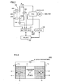
Fig. 2 is a block diagram showing a schematic configuration of the control system for a secondary battery according to the embodiment of the present invention. -
Fig. 3 is a conceptual diagram illustrating a configuration of a battery cell constituting a traveling battery shown inFig. 1 . -
Fig. 4 is a conceptual diagram illustrating a relation between a charging/discharging current and a change in electrolytic solution concentration in a specific type of secondary battery represented by a lithium ion secondary battery. -
Fig. 5 is a conceptual diagram illustrating a relation between the change in electrolytic solution concentration and increase in internal resistance, in the specific type of secondary battery represented by a lithium ion secondary battery. -
Fig. 6 is a schematic block diagram illustrating the configuration of the control system for a secondary battery according to the embodiment of the present invention. -
Fig. 7 is a conceptual diagram showing characteristics of a degree of change in electrolytic solution concentration relative to charging/discharging time involving charging/discharging with a fixed current. -
Fig. 8 is a flowchart illustrating a control structure of a subroutine for implementing operations of a concentration change ratio estimating unit shown inFig. 6 through software processing performed by a battery ECU. -
Fig. 9 is a flowchart illustrating a control structure of a subroutine for implementing operations of a concentration estimated value calculating unit shown inFig. 6 through software processing performed by the battery ECU. -
Fig. 10 is a flowchart illustrating a control structure of a subroutine for implementing operations of a determining unit shown inFig. 6 through software processing performed by the battery ECU. -
Fig. 11 is a flowchart illustrating a control structure of a subroutine for implementing operations of a charging/discharging condition modifying unit shown inFig. 6 through software processing performed by the battery ECU. -
Fig. 12 is a conceptual diagram illustrating one exemplary setting of charging/discharging power upper limit values. -
Fig. 13 shows a table illustrating types of charging/discharging power upper limit values and time limits for durations of charging/discharging with upper limit electric powers. -
Fig. 14 is a flowchart showing a control structure of the control method for a secondary battery according to the embodiment of the present invention. -
Fig. 15 is a schematic block diagram showing a concentration estimating unit of a first variation of the embodiment of the present invention. -
Fig. 16 is a flowchart illustrating a control structure of a subroutine for implementing operations of a concentration change ratio estimating unit shown inFig. 15 through software processing performed by the battery ECU. -
Fig. 17 is a block diagram showing a determining configuration according to a second variation of the embodiment of the present invention. -
Fig. 18 is a conceptual diagram illustrating how to figure out a tendency of usage of the secondary battery using a tendency sensing unit shown inFig. 17 . -
Fig. 19 is a flowchart illustrating a control structure of a subroutine for implementing operations of the determining configuration shown inFig. 17 through software processing performed by the battery ECU. - 11p: positive electrode terminal; 11n: negative electrode terminal; 12: negative electrode; 13, 16: current collector; 14: separator; 15: positive electrode; 18: active material; 100: hybrid vehicle; 120: engine; 140A, 140B: motor generator; 160: driving wheel; 180: speed reducer; 190: motive power splitting mechanism; 200: control system; 202, 202#: electrolytic solution concentration estimating unit; 204: charging/discharging control unit; 205: battery state estimating unit; 210: concentration change ratio estimating unit (in use); 215: concentration change ratio estimating unit (not in use); 220: traveling battery; 220#: battery cell; 221, 225: map; 222: current sensor; 224: temperature sensor; 226: voltage sensor; 230: concentration estimated value calculating unit; 240, 241: inverter; 242: converter; 250, 255: determining unit; 250#: determining configuration; 252: concentration change detecting unit; 254: tendency sensing unit; 260: charging/discharging condition modifying unit; 300: MG_ECU; 310: battery ECU; 320: HV_ECU; 410: accelerator pedal; 415: accelerator pedal sensor; 420: brake pedal; 425: brake pedal sensor; 450: brake actuator; 460: brake mechanism; 465: disc rotor; B#: electrolytic solution concentration estimated value; B0: initial concentration; FL: flag (inside/outside normal range); h(N1, N2): tendency management value; Ib: battery current (charging/discharging current); t(Win): charging time limit; t(Wout): discharging time limit; Tb: battery temperature; tbat: charging/discharging time; Tbst: battery temperature (not in use); Trg: trigger signal; tst: non-use time; Vb: battery voltage; Win: charging power upper limit value; Wout: discharging power upper limit value; α1, α2, β1, β2: criteria value; ΔB: ratio of change in electrolytic solution concentration (for each charging/discharging, during non-use period); ΔB#(n): amount of change in electrolytic solution concentration (predetermined period); ΔR: amount of increase in internal resistance.
- An embodiment of the present invention will be described below in detail with reference to figures. The same or equivalent portions in the figures are given the same reference characters and will not be described repeatedly in principle.
-
Fig. 1 is a control block diagram of a hybrid vehicle presented as a representative example of an electrically powered vehicle having a control system for a secondary battery according to the embodiment of the present invention. -
Fig. 1 is the control block diagram of the hybrid vehicle presented as the representative example of the electrically powered vehicle having a secondary battery controlled by the control system for a secondary battery and a control method therefor both according to the embodiment of the present invention. It should be noted that the electrically powered vehicle is not limited to the hybrid vehicle shown inFig. 1 and the present invention is applicable to hybrid vehicles having other configurations (for example, a series type hybrid vehicle). - Referring to
Fig. 1 ,hybrid vehicle 100 includes an internal combustion engine (hereinafter, simply referred to as "engine") 120 such as a gasoline engine or a diesel engine, and a motor generator (MG) 140, serving as a vehicle driving force generating source.Motor generator 140 includes amotor generator 140A (hereinafter, also simply referred to as "motor 140A" for ease of description) mainly serving as a motor, and amotor generator 140B (hereinafter, also simply referred to as "motor 140B" for ease of description) mainly serving as a generator. It should be noted thatmotor 140A may operate as a generator andgenerator 140B may operate as a motor, depending on a traveling state ofhybrid vehicle 100. - In addition to these,
hybrid vehicle 100 includes aspeed reducer 180 for transmitting to adriving wheel 160 the motive powers generated byengine 120 andmotor generator 140A and for transmitting a driving power from drivingwheel 160 toengine 120 andmotor generator 140A; a motive power splitting mechanism (for example, planetary gear mechanism) 190 for distributing the motive power generated byengine 120 into two paths, i.e., drivingwheel 160 andgenerator 140B; a travelingbattery 220 for charging electric power for drivingmotor generators battery 220 from/to alternating current ofmotor generator 140A; and an inverter 241 for controlling current while converting direct current of travelingbattery 220 from/to alternating current ofmotor generator 140B. - Traveling
battery 220 corresponds to the "secondary battery" controlled by the control system and control method for a secondary battery according to the embodiment of the present invention. -
Hybrid vehicle 100 further includes a battery control unit (hereinafter, referred to as battery ECU (Electronic Control Unit)) 310 for managing and controlling charging/discharging of travelingbattery 220; anengine ECU 280 for controlling an operation state ofengine 120; anMG_ECU 300 for controllingmotor generators battery ECU 310, inverter 240, and the like in accordance with a state of the hybrid vehicle; and anHV_ECU 320 for controlling the entire hybrid system by mutually managing and controlling battery ECU310,engine ECU 280,MG_ECU 300, and the like to operatehybrid vehicle 100 most effectively. - An
accelerator pedal sensor 415 is connected toaccelerator pedal 410 operated by a driver, and generates an output voltage according to a driver-operated amount (pedal angle) ofaccelerator pedal 410. Likewise, abrake pedal sensor 425 is connected to abrake pedal 420 operated by a driver, and generates an output voltage according to driver-operated amount (pedaling force) ofbrake pedal 420. The output voltages ofaccelerator pedal sensor 415 andbrake pedal sensor 425 are sent toHV_ECU 320. Thus,HV_ECU 320 can detect the driver-operated amounts ofaccelerator pedal 410 andbrake pedal 420. - In the present embodiment, a
converter 242 is provided between travelingbattery 220 and inverter 240. Accordingly, even when travelingbattery 220 has a rated voltage smaller than those ofmotor generator 140A andmotor generator 140B,converter 242 steps up or down the voltage, whereby electric power can be exchanged between travelingbattery 220 andmotor generators Converter 242 has a built-in smoothing capacitor not shown in the figures, and the smoothing capacitor is capable of storing electric charges therein whenconverter 242 operates to step up a voltage. - In
Fig. 1 , the ECUs are configured separately but may be configured as an ECU in which two or more ECUs are incorporated (one example of such an ECU is, for example, one havingMG_ECU 300 andHV_ECU 320 incorporated therein as indicated by a dotted line inFig. 1 ). - As motive
power splitting mechanism 190, a planetary gear mechanism (planetary gear) is representatively used to distribute the motive power generated byengine 120 to bothdriving wheel 160 andmotor generator 140B. By controlling the rotation speed ofmotor generator 140B, motivepower splitting mechanism 190 also serves as a continuously variable transmission. Torque ofengine 120 is input to a planetary carrier (C), and is transmitted tomotor generator 140B by a sun gear (S) and is transmitted to the motor and an output shaft (thedriving wheel 160 side) by a ring gear (R). When stoppingengine 120 currently being rotated, kinetic energy resulting from the rotation ofengine 120 is converted bymotor generator 140B into electric energy to decrease the rotation speed ofengine 120. - In
hybrid vehicle 100 having the hybrid system mounted thereon as shown inFig. 1 , whenengine 120 is poor in efficiency at startup or during slow speed traveling, the hybrid vehicle travels only usingmotor 140A ofmotor generator 140. During normal traveling, for example, motivepower splitting mechanism 190 splits the motive power provided fromengine 120 into the two paths, thereby directly drivingdriving wheel 160 on one hand and drivinggenerator 140B to generate electric power on the other hand. The electric power generated on this occasion is employed to drivemotor 140A to assist driving ofdriving wheel 160. During fast traveling, electric power is supplied from travelingbattery 220 tomotor 140A to increase the output ofmotor 140A, thus providing extra driving power to drivingwheel 160. - Meanwhile, upon deceleration,
motor 140A, which operates according todriving wheel 160, serves as a generator to generate electric power through regenerative braking, and the electric power thus recovered can be stored in travelingbattery 220. - It should be noted that the regenerative braking herein includes braking involving generation of regenerative power when a driver who drives the hybrid car operates the foot brake, as well as deceleration of the vehicle (or halt of acceleration) by easing off the accelerator pedal during traveling to generate regenerative power without operating the foot brake.
- Regenerative power that can be generated is set according to a permissible value (upper limit value) of electric power charged to traveling
battery 220. In other words, while travelingbattery 220 is prohibited from being charged, regenerative power generation is also prohibited and the torque command value ofmotor generator 140A is set at zero. - Further, when an amount of charge in traveling
battery 220 is decreased and travelingbattery 220 therefore particularly needs to be charged, the output ofengine 120 is increased to increase an amount of electric power generated bygenerator 140B. In this way, an amount of charge supplied to travelingbattery 220 is increased. Also during slow speed traveling, the output ofengine 120 is controlled to increase when required, for example, when travelingbattery 220 needs to be charged as described above, when driving an auxiliary device such as an air conditioner, when increasing the temperature of coolant inengine 120 to a predetermined temperature, and the like. - Each of
driving wheel 160 and wheels not shown in the figures is provided with abrake mechanism 460.Brake mechanism 460 is configured to obtain braking force of the vehicle from friction force generated by pressing adisc rotor 465, which is provided corresponding to each wheel, with a brake pad (friction material) operated by hydraulic pressure generated bybrake actuator 450. An amount of hydraulic pressure generated bybrake actuator 450 is controlled byHV_ECU 320. -
HV_ECU 320 calculates total braking force required by the entire vehicle, from the operated amount ofbrake pedal 420 and the like.HV_ECU 320 performs control so that the total required braking force thus calculated is generated cooperatively by regenerative braking force provided bymotor 140A and hydraulic braking force provided bybrake mechanism 460. -
Fig. 2 shows a schematic configuration of the control system for a secondary battery according to the embodiment of the present invention. - Traveling
battery 220 is constituted by a battery pack in which a plurality ofbattery cells 220# are connected to one another. As described below, travelingbattery 220 is constituted representatively by a lithium ion secondary battery. - Traveling
battery 220 is connected tomotor generators converter 242. In other words, in the present embodiment, a PCU (Power Control Unit) made up of inverters 240, 241, andconverter 242, as well asmotor generators battery 220. - Further, there are provided a
voltage sensor 226 for detecting a terminal voltage (hereinafter, referred to as "battery voltage Vb") of travelingbattery 220, and acurrent sensor 222 for detecting a current flowing in travelingbattery 220. Anothervoltage sensor 226 may be further provided, in order to measure not only the voltage between the terminals but also an output voltage of each battery block (not shown) constituted by a predetermined number ofbattery cells 220#. - In the description below, the input/output current, detected by
current sensor 222, between travelingbattery 220 and the load will be referred to as "battery current Ib". It should be noted that a direction indicated by an arrow in a figure is defined as the positive current direction of battery current Ib. In other words, Ib > 0 (positive) upon discharging, whereas Ib < 0 (negative) upon charging. Hence, input/output electric power to/from the load of travelingbattery 220 is represented by a product of battery voltage Vb and battery current Ib, has a positive value upon discharging, and has a negative value upon charging. - At a plurality of locations in traveling
battery 220,temperature sensors 224 are provided to detect a battery temperature. A reason whytemperature sensors 224 are provided at the plurality of locations is because the temperature of travelingbattery 220 may differ locally. Outputs ofcurrent sensor 222,voltage sensor 226, andtemperature sensors 224 are sent tobattery ECU 310. - Based on these sensor output values,
battery ECU 310 calculates remaining capacity of the battery (SOC) and limits charging/discharging of the battery. - Representatively, the charging/discharging is controlled to match the estimated SOC with a target SOC. Further, to prevent overcharge/overdischarge of traveling
battery 220,battery ECU 310 determines a charging power upper limit value Win (Win ≤ 0) and a discharging power upper limit value Wout (Wout ≥ 0), and sends them to MG_ECU 300 andHV_ECU 320. - For example, charging power upper limit value Win is set to prevent battery voltage Vb from being higher than the maximal permissible voltage (upper limit voltage) or prevent the SOC from being higher than the upper limit management value, due to overcharge. Likewise, discharging power upper limit value Wout is set to prevent battery voltage Vb from being lower than the minimal permissible voltage (lower limit voltage), or prevent the SOC from being lower than the lower limit management value, due to overdischarge. Here, the upper limit voltage and lower limit voltage are determined according to the maximal rated voltage and minimal rated voltage of traveling
battery 220, a voltage allowing for (guaranteeing) operations of the devices (load) connected to travelingbattery 220, or the like. The absolute values of charging/discharging power upper limit values Win, Wout are also varied according to battery temperature Tb, and are kept low when battery temperature Tb is high and low, as compared with those at a normal temperature. - Particularly,
HV_ECU 300 sets an operation command value (representatively, torque command value) for each of motor generators140A, 140B, to charge/discharge traveling battery 220 within a range between charging power upper limit value Win and discharging power upper limit value Wout. For example, the above-described distribution of the output of the vehicular driving power betweenengine 120 andmotor 140A according to a traveling state is considered so that electric power output from travelingbattery 220 and including electric power to be consumed bymotor 140A does not exceed discharging power upper limit value Wout. - Meanwhile, upon regenerative braking, a torque command value (generally, negative torque) for
motor generator 140A is set while electric power input to travelingbattery 220 and including electric power generated bymotor generator 140A is considered not to exceed charging power upper limit value Win. As described above, when a driver operates the brake,HV_ECU 320 cooperatively controls regenerative braking force provided bymotor generator 140A and hydraulic braking force provided bybrake mechanism 460 to obtain a total required braking force from the sum of the braking forces. Hence, even though regenerative braking force provided bymotor generator 140A is limited by charging power upper limit value Win, a required vehicular braking force can be obtained. -
Fig. 3 is a schematic diagram of a battery cell constituting travelingbattery 220 shown inFig. 1 . As described above, travelingbattery 220 is configured as a battery pack in whichbattery cells 220# each shown inFig. 3 are connected in series or in series-parallel. - Referring to
Fig. 3 , each ofbattery cells 220# includes anegative electrode 12, aseparator 14, and apositive electrode 15.Separator 14 is formed by impregnating with an electrolytic solution a resin provided between the negative electrode and the positive electrode.Separator 14 corresponds to an "ionic conductor" in the present invention. - Each of
negative electrode 12 andpositive electrode 15 is constituted by a collection of sphericalactive materials 18. Upon discharging, on an interface ofactive materials 18 innegative electrode 12, an electrochemical reaction occurs to emit a lithium ion Li+ and an electron e-. On the other hand, on interfaces ofactive materials 18 inpositive electrode 15, an electrochemical reaction occurs to absorb lithium ion Li+ and electron e-. -
Negative electrode 12 is provided with acurrent collector 13 for absorbing electron e-, whereaspositive electrode 15 is provided with acurrent collector 16 for emitting electron e-.Current collector 13 of the negative electrode is representatively formed of copper, whereascurrent collector 16 of the positive electrode is representatively formed of aluminum.Current collector 13 is provided with anegative electrode terminal 11n, andcurrent collector 16 is provided with apositive electrode terminal 11p. Lithium ion Li+ is exchanged throughseparator 14, thereby charging/dischargingbattery cells 220#. Accordingly, charging current Ib (> 0) or discharging current Ib (< 0) is generated. - Where
battery cells 220# are constituted by a lithium ion secondary battery, lithium salt serving as a supporting electrolyte is dissolved in a solvent of the electrolytic solution. Here, electrolyte ion concentration in the electrolytic solution ofseparator 14 is hereinafter also simply referred to as "electrolytic solution concentration". - Now, a characteristic of an electrolytic solution concentration in a secondary battery will be described with reference to
Figs. 4 and 5 . The characteristic is noticeable in a specific type of battery such as a lithium ion secondary battery. - Referring to
Fig. 4 , the present inventors found that a specific type of secondary battery has such a characteristic that an amount of change ΔBb in electrolytic solution concentration is not increased so much by charging/discharging with a small current but is abruptly increased by charging/discharging with a large current. Specifically, the electrolytic solution concentration is changed greatly to increase by charging with a large current, and is changed greatly to decrease by discharging with a large current. - Hence, when charging/discharging the secondary battery within the normal current range in use, the secondary battery is repeatedly charged/discharged to adjust the remaining capacity (SOC) to a fixed value and the electrolytic solution concentration do not increase or decrease so much from the initial value (value in the brand new condition).
- However, if a driver of the hybrid vehicle has a characteristic or the like of, for example, frequently accelerating the traveling speed greatly to result in discharging with a large current, the electrolytic solution concentration may greatly decrease from the initial value as the secondary battery is used more. On the other hand, if the hybrid vehicle is driven under use conditions that regenerative power is generated frequently by traveling in a sloping road or the like, the battery tends to be overcharged, with the result that the electrolytic solution concentration may greatly increase from the initial value as the secondary battery is used more.
- Meanwhile, as shown in
Fig. 5 , the present inventors found that a specific type of battery such as a lithium ion secondary battery has such a characteristic that increase in internal resistance is not so noticeable in a region in which amount of change ΔBb in electrolytic solution concentration is not so large, but when amount of change ΔBb in electrolytic solution concentration reaches or exceeds a predetermined value, an amount of increase ΔR in internal resistance is drastically increased from that in the brand new condition. - Namely, when the electrolytic solution concentration is changed from the initial value to enter the region in which the increase of internal resistance is noticeable, the battery's performance may be limited and problems may arise in the life of the secondary battery. Hence, it is appreciated that what is important to efficiently prevent deterioration of a secondary battery is not to feedback the change in internal resistance to modify the charging/discharging condition, but is to control charging/discharging so that the change in electrolytic solution concentration falls within the normal range at a stage before the change in internal resistance.
- In view of such findings, the control system and control method for a secondary battery according to the embodiment of the present invention controls charging/discharging of the secondary battery to maintain the electrolytic solution concentration within a predetermined normal range, as described below.
-
Fig. 6 is a schematic block diagram showing a configuration of the control system for a secondary battery in the embodiment of the present invention. - Referring to
Fig. 6 ,control system 200 for a secondary battery according to the embodiment of the present invention includes an electrolytic solutionconcentration estimating unit 202 configured to estimate electrolytic solution concentration based on a use state of the secondary battery; and a charging/dischargingcontrol unit 204 for controlling charging/discharging of the secondary battery based on an electrolytic solution concentration estimated value B# provided by electrolytic solutionconcentration estimating unit 202, so as to maintain the electrolytic solution concentration within the normal range. -
Control system 200 further includes a batterystate estimating unit 205 for estimating a state of the secondary battery based on quantities of state of the secondary battery such as battery temperature Tb, battery current Ib, and battery voltage Vb to find a remaining capacity estimated value (estimated SOC). Based on estimated SOC and the battery state (representatively, battery temperature Tb), batterystate estimating unit 205 sets charging power upper limit value Win and discharging power upper limit value Wout of the secondary battery. - Electrolytic solution
concentration estimating unit 202 includes a concentration changeratio estimating unit 210 for estimating a ratio of change ΔB in the electrolytic solution concentration during use of the secondary battery based on the charging/discharging current (battery current Ib) in response to an on signal PON for a power switch for operating the hybrid system, i.e., a signal corresponding to an instruction for starting driving ofhybrid vehicle 100; and a concentration estimatedvalue calculating unit 230 for sequentially calculating electrolytic solution concentration estimated value B# in accordance with estimated ratio of change ΔB during use of the secondary battery. Concentration changeratio estimating unit 210 includes amap 221 for estimating ratio of change ΔB in the electrolytic solution concentration based on the charging/discharging current. - Charging/discharging
control unit 204 includes a determiningunit 250 for determining whether or not the electrolytic solution concentration is within the normal range, based on electrolytic solution concentration estimated value B# estimated by concentration estimatedvalue calculating unit 230; and a charging/dischargingcondition modifying unit 260 for modifying a charging/discharging condition of the secondary battery according to a flag FL indicative of a result of determination by determiningunit 250, to bring the electrolytic solution concentration back to the normal range when the electrolytic solution concentration falls out of the normal range. - The following describes operations of each block in detail. Described first are operations of concentration change
ratio estimating unit 210 and concentration estimatedvalue calculating unit 230 both constituting electrolytic solutionconcentration estimating unit 202. - As shown in
Fig. 7 , electrolytic solution concentration in the secondary battery changes according to charging/discharging of the secondary battery.Fig. 7 shows characteristics of a ratio of change ΔB in electrolytic solution concentration caused by charging/discharging with a fixed current, relative to time tbat (horizontal axis) of charging/discharging with the current. Such characteristics can be found by measuring changes in electrolytic solution concentration during an experiment of actually charging/discharging the secondary battery with currents of various values. - Based on the result of such an experiment, ratio of change ΔB in electrolytic solution concentration caused by charging/discharging of the secondary battery can be represented as ΔB = f(Ib, tbat) where f(Ib, tbat) is a function of charging/discharging current Ib and charging/discharging time tbat. Assume that ratio of change ΔB is represented by ratio of change (%) from the electrolytic solution concentration at the start of the charging/discharging. Namely, the initial value thereof at the start of the charging/discharging (tbat = 0) is ΔB = 0.
- As shown in
Fig. 7 , as absolute value |Ib| of the charging/discharging current is larger, absolute value |ΔB| of the ratio of change in electrolytic solution concentration tends to be larger. Particularly, when the charging/discharging current reaches or exceeds a predetermined value, absolute value |ΔBb| of the amount of change is drastically larger. - More specifically, based on function f(Ib, tbat) representing the characteristics found by the previously conducted experiments and the like with various currents as shown in
Fig. 7 , map 221 can be constructed to extract ratio of change ΔB = f(Ib, tbat) as a map value according to charging/discharging current Ib and charging/discharging time tbat. In this way, whenever charging/discharging of the secondary battery with a fixed current is finished, ratio of change ΔB in electrolytic solution concentration caused by the charging/discharging can be calculated with reference to map 221. -
Fig. 8 is a flowchart illustrating a control structure of a subroutine for implementing operations of concentration changeratio estimating unit 210 through software processing performed bybattery ECU 310. - Referring to
Fig. 8 , in a step S111,battery ECU 310 determines based on the PON signal whether or not the power is on, i.e., the secondary battery is in use. If the secondary battery is in a period of no use (NO in S111), the subroutine is terminated without terminating the following processing. - On the other hand, if the secondary battery is in use (YES in S111), in a step S112,
battery ECU 310 obtains battery current Ib at present. Then, in a step S113,battery ECU 310 compares it with that at the previous execution of the subroutine and determines whether or not an amount of change in battery current Ib is equal to or smaller than a predetermined value. In other words, instep S 113, whether or not charging/discharging with the fixed current is continued is determined. - If NO is determined in step S113, i.e., if battery current Ib has not been changed,
battery ECU 310 determines that charging/discharging with the fixed current is continuing, and increments in a step S 114 a counter value for measuring duration time of the charging/discharging. - On the other hand, if YES is determined in
step S 113, i.e., if battery current Ib has been changed from that at the previous execution of the subroutine,battery ECU 310 determines that the charging/discharging with the fixed current has been ended, and performs processing of steps S 115,S 116 to estimate ratio of change ΔB in electrolytic solution concentration caused by the charging/discharging. - Based on the counter value counted thus far in step S 114,
battery ECU 310 calculates in step S 115 time tbat of charging/discharging with the fixed current. Instep S 116, it makes reference to map 221 constructed based on current Ib for the charging/discharging and the charging/discharging time calculated in step S 115, in order to calculate ratio of change ΔB = f(Ib, tbat). In this way, whenever one event of charging/discharging with the fixed current is ended, ratio of change ΔB in electrolytic solution concentration caused by the charging/discharging is calculated. - It should be noted that the characteristics shown in
Fig. 7 may be set after conducting an experiment for each battery temperature Tb. In this case,map 221 is configured to calculate ratio of change ΔB = f(Ib, Tb, tbat) as a map value according to charging/discharging current Ib, charging/discharging time tbat, and battery temperature Tb. - Alternatively, since ratio of change ΔB may change according to an electrolytic solution concentration level at a certain time, in order to accommodate such a change, map 221 may be configured to calculate ratio of change ΔB = f(Ib, tbat, B#) according to charging/discharging current Ib, charging/discharging time tbat, and electrolytic solution concentration estimated value B# at the time, with electrolytic solution concentration levels being assigned in advance and the characteristics in
Fig. 7 being found. - As such, concentration change
ratio estimating unit 210 can be configured so that ratio of change ΔB in electrolytic solution concentration caused by the charging/discharging is calculated based on at least charging/discharging current Ib and charging/discharging time tbat or is calculated while reflecting, in addition to these, battery temperature Tb and/or electrolytic solution concentration estimated value B# at the start of the charging/discharging. -
Fig. 9 is a flowchart illustrating a control structure of a subroutine for implementing operations of concentration estimatedvalue calculating unit 230 shown inFig. 6 through software processing. - Referring to
Fig. 9 , in a step S121,battery ECU 310 determines whether or not concentration changeratio estimating unit 210 has calculated ratio of change ΔB. As described above, ratio of change ΔB is calculated for every one event of ending charging/discharging with the fixed current. Hence, while the charging/discharging with the fixed current is continued, ratio of change ΔB is not calculated and therefore NO is determined in step S121. When NO is determined in step S121,battery ECU 310 maintains electrolytic solution concentration estimated value B# at present (step S123). - On the other hand, if concentration change
ratio estimating unit 210 has calculated ratio of change ΔB (YES in S121), i.e., if the charging/discharging with the fixed current has been ended,battery ECU 310 reflects in step S122 calculated ratio of change ΔB, to update electrolytic solution concentration estimated value B#. - In this way, whenever charging/discharging with the fixed current is ended, a change in electrolytic solution concentration caused by the charging/discharging can be estimated and electrolytic solution concentration estimated value B# can be updated one after another.
- It should be noted that concentration change ratio estimating unit 210 (map 221) can be configured to estimate amount of change ΔBb in electrolytic solution concentration instead of ratio of change ΔB in electrolytic solution concentration. In this case, in the processing in step S112 in
Fig. 9 , calculation of adding ΔBb to electrolytic solution concentration estimated value B# at present is performed for updating. - Alternatively, ratio of change ΔB calculated from
map 221 can be defined corresponding to a product of the slope of a tangent of a curve representing a change of electrolytic solution concentration with time as shown inFig. 7 , and a calculation cycle T (cycle of execution of the subroutine). As such, in the subroutine shown inFig. 8 , also in step S141 performed when battery current Ib is not changed (NO in S 113), ratio of change ΔB is calculated each time according to time tbat of charging/discharging with the current. As a result, in the control structure, ratio of change ΔB in electrolytic solution concentration and electrolytic solution concentration estimated value B# are calculated whenever the subroutine of each ofFigs. 8 and9 is executed. - The following describes determining
unit 250 and charging/dischargingcondition modifying unit 260 constituting charging/dischargingcontrol unit 202 in detail. -
Fig. 10 is a flowchart showing a control structure of a subroutine for implementing operations of determiningunit 250 shown inFig. 6 through software processing performed bybattery ECU 310. - Referring to
Fig. 10 , in step S 13 1,battery ECU 310 checks a value of flag FL indicating whether or not electrolytic solution concentration is within the normal range. In the description herein, it is assumed that flag FL is set at "0" when electrolytic solution concentration is within the normal range and is set at "1" when electrolytic solution concentration is out of the normal range. It should be noted that another flag, which is not described herein, is set to indicate whether electrolytic solution concentration falling out of the normal range is too high or too low when FL = 1. - When FL = 0 (YES in S 131),
battery ECU 310 determines in a step S 132 whether or not the electrolytic solution concentration at present is within the normal range, by determining whether or not electrolytic solution concentration estimated value B# estimated by concentration estimatedvalue calculating unit 230 is changed from an initial concentration (appropriate concentration) B0 by a predetermined value or greater. Specifically, in step S132, whether |B# - B0| > α1 is satisfied or not is determined, where α1 is a predetermined criteria value. - When |B# - B0| > α1 (YES in S 132),
battery ECU 310 determines in a step S 134 that electrolytic solution concentration is out of the normal range, and set flag FL = 1. - On the other hand, when |B# - B0| ≤ α1 (NO in S132),
battery ECU 310 determines in astep S 13 5 that the electrolytic solution concentration is within the normal range and maintains flag FL = 0. - Once it is determined that electrolytic solution concentration is out of the normal range and flag FL = 1 is set, NO is determined in step S 131 and
battery ECU 310 determines in a step S 133 whether or not the electrolytic solution concentration is brought back to the normal range, using a criteria value α2 different from that in step S132. Specifically, in step S133, whether |B# - B0| < α2 is satisfied or not is determined. Criteria value α2 is set at a value smaller than criteria value α1 used in step S132 (α2 < α1). Once it is determined that the electrolytic solution concentration is out of the normal range (FL = 1) and the absolute value of the amount of change in electrolytic solution concentration estimated value B# from initial concentration B0 is smaller than criteria value α2 (YES in S 133),battery ECU 310 determines that electrolytic solution concentration is back to the normal range and update flag FL = 0. - On the other hand, when NO is determined in step S 133,
battery ECU 310 maintains flag FL = 1 in step S134. - As such, there is provided hysterisis between criteria value α1 for determining whether or not electrolytic solution concentration is out of the normal range and criteria value α2 for determining whether or not it is brought back to the normal range from outside the normal range. This can prevent charging/discharging control from being unstable by frequently modifying/stopping modifying a below-described charging/discharging condition due to frequent change (hunting) in results of determination as to whether the electrolytic solution concentration is within or out of the normal range.
-
Fig. 11 is a flowchart showing a control structure of a subroutine for implementing operations of charging/dischargingcondition modifying unit 260 shown inFig. 6 through software processing performed bybattery ECU 310. - Referring to
Fig. 11 , according to flag FL set by determiningunit 250,battery ECU 310 determines in step S141 whether or not the charging/discharging condition needs to be modified. When flag FL = 0 (NO in step S141),battery ECU 310 maintains the charging/discharging condition at a normal condition in a step S143. On the other hand, when flag FL = 1 (YES in step S141), it modifies in a step S 142 the charging/discharging condition to a condition stricter than the normal condition. - Modified in step S 142 are, for example, charging power upper limit value Win and discharging power upper limit value Wout both set by battery
state estimating unit 205 based on the present state of the secondary battery and indicating the limits of charging/discharging, as well as a charging time limit t(Win) and a discharging time limit t(Wout) for the upper limit values. - Now, the limits of charging/discharging power will be described.
-
Fig. 12 is a conceptual diagram illustrating one exemplary setting of charging/discharging power upper limit values Win, Wout. - Referring to
Fig. 12 , batterystate estimating unit 205 sets charging power upper limit value Win and discharging power upper limit value Wout based on battery temperature Tb and estimated SOC at the moment. - As seen from
Fig. 12 , in a high temperature region or a very low temperature region, charging/discharging of the secondary battery is limited as compared with that in a normal temperature region, and Win ≈ 0 and Wout ≈ 0 are set. As such, charging power upper limit value Win and discharging power upper limit value Wout are set variably according to battery temperature Tb and the SOC. - In
Fig. 12 , charging power upper limit value Win and discharging power upper limit value Wout are set symmetrically relative to battery temperature Tb (Wout = -Win), but charging power upper limit value Win and discharging power upper limit value Wout can be set arbitrarily. - As shown in
Fig. 13 , in general, a plurality of types of charging/discharging power upper limit values Win, Wout are set. For each type, charging/discharging power upper limit values as well as time limits t(Win), t(Wout) for durations of charging/discharging with the upper limit electric powers are set. - For example, as standard rated values, charging power upper limit value Win(1) and discharging power upper limit value Wout(1) are set for t1 = approximately 2-5 seconds. Further, for a very short period of time (for example, t2 < approximately 1 second), short-time rated values Win(2), Wout(2) for relaxing the charging/discharging power as compared with the standard rated values to satisfy a driver's output request are set. Furthermore, to limit electric power for charging/discharging continuing for a long period of time, charging power upper limit value Win(3) and discharging power upper limit value Wout(3) are set for t3 = approximately 10 seconds as continuing rated values.
- In these rated values shown in
Fig. 13 , t2 < t1 < t3, |Win(3)| < |Win(1)| < |Win(2)|, and Wout(3) < Wout(1) < Wout(2). For these rated values (charging/discharging power upper limit values and time limits) for charging/discharging, a map similar to that inFig. 12 is prepared in advance and is set according to a state of the secondary battery (for example, battery temperature and estimated SOC). - In the present embodiment, unless otherwise noted, charging power upper limit value Win and discharging power upper limit value Wout are also intended to encompass Win(1)-Win(3) and Wout(1)-Wout(3) respectively. Likewise, time limits t(Win), t(Wout) for durations of charging/discharging are also intended to encompass t1-t3.
- Referring to
Fig. 11 again, when flag FL = 0, in step S 143,battery ECU 310 employs charging/discharging rated values Win, Wout, t(Win), t(Wout) set by batterystate estimating unit 205 and shown inFigs. 12 and13 , without modification. - On the other hand, when flag FL=1,
battery ECU 310 modifies at least one of Win, Wout, t(Win), and t(Wout) in step S 142. - As described above, when flag FL = 1, determining
unit 250 further provides information indicating whether the electrolytic solution concentration is increased too much or is decreased too much. - Based on the information, when the electrolytic solution concentration is increased to go out of the normal range,
battery ECU 310 modifies charging power upper limit value Win (at least one of Win(1)-(3)) to Win# to decrease the absolute value thereof, thus avoiding the tendency of overcharge. Alternatively, the tendency of overcharge can be avoided by modifying time limit t(Win) for the upper limit electric power to t#(Win) so as to make the time limit shorter than usual. Alternatively, both charging power upper limit value Win and time limit t(Win) may be modified. - On the other hand, when the electrolytic solution concentration is decreased to go out of the normal range,
battery ECU 310 modifies discharging power upper limit value Wout (at least one of Wout(1)-(3)) to Wout# to decrease the absolute value thereof, thus avoiding the tendency of overdischarge. Alternatively, the tendency of overdischarge may be avoided by modifying time limit t(Wout) for the upper limit electric power to t#(Wout) so as to make the time limit shorter than usual. Alternatively, both discharging power upper limit value Wout and time limit t(Wout) may be modified. - In this way, by modifying the charging/discharging power upper limit values and/or the time limits for the charging/discharging with the upper limit electric power, the charging/discharging condition of the secondary battery can be modified to bring back to the normal range the electrolytic solution concentration having fallen out of the normal range, thus avoiding the tendency of overcharge or overdischarge.
- It should be noted that the modification of the charging/discharging condition by charging/discharging
condition modifying unit 260 is not limited to the change of the above-described limits of charging/discharging (charging/discharging power upper limit values and/or time limits for charging/discharging with the upper limit electric power). For example, the charging/discharging condition of the secondary battery can be modified to avoid the tendency of charging or discharging the secondary battery too much, by modifying a charging current level in a mode of charging travelingbattery 220 using electric power generated bygenerator 140B through an output ofengine 120, or by modifying the distribution of driving powers betweenengine 120 andmotor 140A during traveling of the vehicle. - As described above, in the control system for a secondary battery according to the present embodiment, the charging/discharging condition of the secondary battery can be modified based on the use state of the secondary battery. Specifically, a change in electrolytic solution concentration caused by use (charging/discharging) of the secondary battery is estimated, and when the electrolytic solution concentration thus estimated is out of the normal range, the charging/discharging condition can be modified to bring the electrolytic solution concentration back to the normal range. Therefore, by controlling charging/discharging of the secondary battery to maintain the electrolytic solution concentration within the normal range, progress of deterioration of the secondary battery can be prevented before occurrence of noticeable deterioration such as increase of internal resistance, thus achieving longer life thereof.
- It should be noted that the control system of the secondary battery shown in
Fig. 6 can be implemented in software bybattery ECU 310 through a combination of the subroutines shown inFigs. 8 ,9 ,10 , and11 , in accordance with the flowchart shown inFig. 14 . - Referring to
Fig. 14 , the control method for a secondary battery according to the embodiment of the present invention includes: step S102 of estimating electrolytic solution concentration based on a use state of the secondary battery; and step S 104 of controlling charging/discharging of the secondary battery based on the electrolytic solution concentration thus estimated, to maintain the electrolytic solution concentration within the normal range. Step S 102 includes: step S110 of estimating a ratio of change in electrolytic solution concentration by executing the subroutine shown inFig. 8 ; and step S120 of sequentially calculating an estimated value of the electrolytic solution concentration by executing the subroutine shown inFig. 9 . - Similarly, step S104 includes: step S 130 of determining whether or not the electrolytic solution concentration is within the normal range by executing the subroutine shown in
Fig. 10 ; and stepS 140 of modifying the charging/discharging condition to bring the electrolytic solution concentration back to the normal range by executing the subroutine shown inFig. 11 when it is determined that the electrolytic solution concentration is out of the normal range. - Namely, the processing in step S 110 corresponds to the operation of concentration change
ratio estimating unit 210 inFig. 6 , the processing in step S120 corresponds to the operation of concentration estimatedvalue calculating unit 230 inFig. 6 , the processing in step S130 corresponds to the operation of determiningunit 250 inFig. 6 , and the processing instep S 140 corresponds to the operation of charging/dischargingcondition modifying unit 260 inFig. 6 . As such, a predetermined program stored in advance inbattery ECU 310 to implement the flowchart shown inFig. 14 is executed at a predetermined cycle, whereby the control system shown inFig. 6 implements control for charging/discharging the secondary battery. - In a first variation, a variation of the configuration of electrolytic solution
concentration estimating unit 202 shown inFig. 6 will be described. - Referring to
Fig. 15 , an electrolytic solutionconcentration estimating unit 202# according to the first variation of the embodiment of the present invention is different from the configuration of electrolytic solutionconcentration estimating unit 202 shown inFig. 6 , in that it further includes a concentration changeratio estimating unit 215 for estimating ratio of change ΔB in electrolytic solution concentration during a non-use period of the secondary battery (for example, an off period of the power switch, i.e., an off period of the PON signal). - Ratio of change ΔB in electrolytic solution concentration estimated by concentration change
ratio estimating unit 215 is transmitted to concentration estimatedvalue calculating unit 230 at the start of using the secondary battery (for example, when OFF → ON of the PON signal). Concentration changeratio estimating unit 215 includes amap 225 for calculating ratio of change ΔB in electrolytic solution concentration during the non-use period of the secondary battery.Map 225 is configured to reflect such a characteristic that the electrolytic solution concentration is changed to get closer to initial concentration B0 during the non-use period of the secondary battery due to an effect of relaxation of the secondary battery. - As known well, the effect of relaxation of the secondary battery is greatly influenced by battery temperature Tb. Hence, based on results of previously conducted experiments,
map 225 is configured so that ratio of change ΔB = g(Tbst, tst) is extracted as a map value in accordance with battery temperature Tbst and relaxation time, i.e., non-use time tst of the secondary battery, during the non-use period of the secondary battery (relaxation period). In this way, whenever the secondary battery starts to be used, ratio of change ΔB in electrolytic solution concentration during the non-use period of the secondary battery can be estimated. - When ending the use of the secondary battery (ON → OFF of the PON signal), concentration estimated
value calculating unit 230 causes a nonvolatile memory region not shown in the figures to store electrolytic solution concentration estimated value B# at the moment. When starting to use the secondary battery (OFF → ON of the PON signal), concentration estimatedvalue calculating unit 230 calculates an electrolytic solution concentration estimated value B# at the start of use thereof according to electrolytic solution concentration estimated value B# stored in the nonvolatile memory region and ratio of change ΔB having occurred during the non-use period and provided from concentration changeratio estimating unit 215. - In this way, the change in electrolytic solution concentration caused by the effect of relaxation during the non-use period of the secondary battery (change toward initial concentration B0) can be also reflected, whereby the electrolytic solution concentration can be estimated more accurately.
-
Fig. 16 is a flowchart showing a control structure of a subroutine executed instead of the subroutine ofFig. 8 to implement operations of concentration changeratio estimating unit 210 and concentration changeratio estimating unit 215 through software processing performed bybattery ECU 310. - Referring to
Fig. 16 , for estimation of the ratio of change in concentration in the first variation of the embodiment of the present invention,battery ECU 310 performs steps S 117, S 118, S119a-S119c in addition to steps S111-S116 shown in the flowchart ofFig. 8 . - Prior to step S111,
battery ECU 310 performs step S 117 to detect start of use of the secondary battery, i.e., to detect transition of the PON signal from off to on. When NO is determined in step S 117, i.e., at a time other than the start of use of the secondary battery,battery ECU 310 performs steps S111 to S116 as with those inFig. 8 . When NO is determined in step S111, i.e., during the non-use period of the secondary battery,battery ECU 310 performs step S 118 to periodically obtain temperature data for battery temperature Tb. Alternatively, if the ECU is designed not to obtain a trigger for measuring battery temperature Tb during the non-use time of the secondary battery, step S118 may not be performed. - Meanwhile, when YES is determined in step S117, i.e., at the start of use of the secondary battery,
battery ECU 310 performs processing of steps S 119a-S119c. - In step S 119a,
battery ECU 310 obtains non-use time tst of the secondary battery based on the passage of time from the moment that the PON signal has become off to the moment that the PON signal has become on. Further, in step S 119b,battery ECU 310 obtains battery temperature Tbst during the non-use time of the secondary battery based on, for example, the temperature data obtained in step S 118. It should be noted that if the temperature data cannot be obtained during the non-use period of the secondary battery, battery temperature Tbst during the non-use period can be estimated based on battery temperature Tb at the moment that the PON signal has become off, battery temperature Tb at present, and optionally a temperature of external air. - Further,
battery ECU 310 performs step S 119c to obtain ratio of change ΔB=g(Tbst, tst) according to at least non-use time tst and battery temperature Tbst during the non-use period through processing similar to that of making reference to map 225 ofFig. 15 , based on an actual measurement value of the previously experimented effect of relaxation and the like. - In this way, ratio of change ΔB in electrolytic solution concentration during the non-use period of the battery is calculated at the start of use of the secondary battery. At the start of use of the secondary battery, the subroutine shown in
Fig. 9 determines YES in step S121 in response to the calculation of ratio of change ΔB. Hence, at the start of use of the secondary battery, the effect of relaxation during the non-use period of the secondary battery can be reflected in calculation of electrolytic solution concentration estimated value B#. As such, the estimation of electrolytic solution concentration according to the first variation of the present embodiment also can be implemented through software processing performed bybattery ECU 310. - In the first variation of the present embodiment, concentration change ratio estimating unit 215 (map 225) can be configured to estimate amount of change ΔBb in electrolytic solution concentration instead of ratio of change ΔB in electrolytic solution concentration.
- Described in a second variation is a variation of determining
unit 250 shown inFig. 6 for determining whether or not the electrolytic solution concentration is within the normal range. -
Fig. 17 is a block diagram showing a determiningconfiguration 250# of the second variation of the embodiment of the present invention. - Referring to
Fig. 17 , determiningconfiguration 250# includes a concentrationchange detecting unit 252, atendency sensing unit 254, and a determiningunit 255. - Concentration
change detecting unit 252 receives an electrolytic solution concentration estimated value B# from concentration estimatedvalue calculating unit 230, and a trigger signal Trg indicating passage of a predetermined period. - Trigger signal Trg is generated whenever the predetermined period has passed or
hybrid vehicle 100 has traveled for a predetermined distance, during the use period of the secondary battery, i.e., during the period of traveling ofhybrid vehicle 100. Alternatively, trigger signal Trg may be generated in response to on/off of the power switch of the hybrid vehicle. In this way, the predetermined period corresponds to one trip of the hybrid vehicle (start of driving to end of driving). - Whenever each predetermined period passes, concentration
change detecting unit 252 calculates an amount of change ΔB#(n) in concentration, which is defined by a difference between an initial value (at the start of the predetermined period) and a final value (at the end of the predetermined period) of electrolytic solution concentration estimated value B#. Here, n represents a value incremented by one whenever a predetermined period starts. - As shown in
Fig. 18 ,tendency sensing unit 254 calculates a count value N1 and a count value N2 based on amount of change ΔB#(n) in concentration during each predetermined period. During the predetermined period, count value N1 is counted up whenever the electrolytic solution concentration is increased to go above a predetermined criteria value β1 whereas count value N2 is counted up whenever the electrolytic solution concentration is decreased to go below a criteria value β2. - Based on count values N1 and N2,
tendency sensing unit 254 calculates a tendency management values h(N1, N2) indicating a tendency of use of the secondary battery. Tendency management value h(N1, N2) is expressed by, for example, N1/N or N2/N, which indicates in probability how frequent the electrolytic solution concentration goes above or below criteria values β1, β2. Here, N represents a natural number indicating the total of the predetermined periods. - Determining
unit 255 determines a flag FL based on tendency management value h(N1, N2) found bytendency sensing unit 254. As with that in determiningunit 250, flag FL = 0 is set when it is determined that the electrolytic solution concentration is within the normal range, and flag FL = 1 is set when it is determined that the electrolytic solution concentration is out of the normal range and the charging condition needs to be modified. - For example, when probability N1/N goes above the predetermined criteria value, determining
unit 255 can detect a tendency in which the secondary battery is used to increase the electrolytic solution concentration, i.e., tendency of usage toward overcharge. On the other hand, when probability N2/N goes below the predetermined criteria value, determiningunit 255 can detect a tendency in which the secondary battery is used to decrease the electrolytic solution concentration, i.e., a tendency of usage toward overdischarge. - Alternatively, when a probability (N1-N2)/N found based on a difference between count values N1 and N2 is employed as tendency management value h(N1, N2), an overall tendency of usage can be figured out while canceling the periods during which the electrolytic solution concentration is increased too much and is decreased too much. On this occasion, by using a weighting coefficient to employ tendency management value h(N1, N2) = (k1·N1-k2·N2)/N or by using different criteria values for the probabilities N1/N and N2/N, the overall tendency of usage can be also figured out to cancel a tendency of error in estimation done by electrolytic solution
concentration estimating unit 202. - As such, amount of change ΔB#(n) in concentration of the electrolytic solution is found one after another for each predetermined period, and the tendency of usage of the secondary battery is figured out by tendency management value h(N1, N2), whereby it can be detected whether the tendency of usage of the secondary battery is a tendency toward overcharge or a tendency toward overdischarge before electrolytic solution concentration estimated value B# is changed from initial concentration B0 to exceed criteria value α1 (
Fig. 10 ). - In this way, according to the tendency of usage of the secondary battery, i.e., the characteristics of the driver who drives
hybrid vehicle 100, the modification of the charging/discharging condition in the present embodiment can be started to prevent the electrolytic solution concentration from increasing or decreasing too much. As a result, the secondary battery can be prevented more effectively from deteriorating due to increase or decrease of the electrolytic solution concentration. -
Fig. 19 is a flowchart showing a control structure of a subroutine executed instead of the subroutine ofFig. 10 to implement operations of determiningconfiguration 250# shown inFig. 17 through software processing performed bybattery ECU 310. - Referring to
Fig. 19 , for the determinations in the second variation of the embodiment of the present invention,battery ECU 310 performs steps S 136-S 139 in addition to steps S 131-S 13 5 shown in the flowchart ofFig. 10 . The determinations by steps S132, S133 are replaced with determinations by steps S132#, S133#. - In step S 136,
battery ECU 310 determines, in response to trigger signal Trg shown inFig. 17 , whether or not a predetermined period has been ended. If NO is determined in step S136, i.e., while the predetermined period has not been ended yet, the present value of flag FL is maintained in step S 139. - On the other hand, if YES is determined in step S136, i.e., whenever each predetermined period ends,
battery ECU 310 calculates in step S 137 amount of change ΔB#(n) in concentration of the electrolytic solution during the predetermined period. In step S138,battery ECU 310 calculates tendency management value h(N1, N2) according to count values N1, N2 found based on amounts of change ΔB#(1)-ΔB#(N) in concentration during each predetermined period. - In step S132#,
battery ECU 310 determines whether to change FL from 0 to 1, based on whether or not tendency management value h(N1, N2) calculated in step S138 exceeds a criteria value A1. Once tendency management value h(N1, N2) reaches or goes below a criteria value A2 (A2 < A1) after flag FL = 1 is set,battery ECU 310 sets flag FL = 0 again in step S133#. - As such, there is provided hysterisis between criteria value A1 for determining whether or not the electrolytic solution concentration falls out of the normal range and criteria value A2 for determining whether or not the electrolytic solution concentration comes back to the normal range from outside the normal range. Hence, as with the flowchart in
Fig. 10 , control for charging/discharging can be prevented from being unstable by frequent changes (hunting) in the results of determination as to whether the electrolytic solution concentration is inside/outside the normal range and by accordingly frequently modifying/stopping modifying the charging/discharging condition according to the present embodiment. As such, the determination according to the second variation of the present embodiment as to whether the electrolytic solution concentration is inside/outside the normal range can be also implemented through software processing performed bybattery ECU 310. - It should be noted that in the present embodiment and the variations thereof, a lithium ion secondary battery is illustrated as the secondary battery
constituting traveling battery 220, but a battery other than a lithium ion secondary battery is also applicable to the control system and control method for a secondary battery according to the embodiment of the present invention and the variation thereof as long as the battery is of a type having the characteristics shown inFigs. 4 and 5 . - Further, in the embodiment of the present invention and the variations thereof, the electrically powered vehicle illustrated as
hybrid vehicle 100 may be a hybrid vehicle, an electric car having no internal combustion engine, or a fuel cell car having a fuel cell for generating electric energy using fuel. - It should be also noted that in the description above, the software processing by
battery ECU 310 is actually executed by a CPU (Central Processing Unit) not shown in the figures, and the CPU can be configured to read out from a ROM (Read Only Memory) a program including each of the steps described in the illustrated flowcharts, and execute the readout program to perform processing according to the flowcharts. Hence, the ROM corresponds to a computer (CPU) readable storage medium storing thereon the program including each of the steps of the flowcharts described in each embodiment. - Although the present invention has been described and illustrated in detail, it is clearly understood that the same is by way of illustration and example only and is not to be taken by way of limitation, the scope of the present invention being interpreted by the terms of the appended claims.
Claims (30)
- A control system for a secondary battery (220) configured to exchange electric power with a load,
said secondary battery including
first and second electrodes (12, 15) each configured to include an active material (18) containing a predetermined material, and
an ionic conductor (14) for conducting said predetermined material which is ionized between said first and second electrodes,
the control system comprising:a concentration estimating unit (202) configured to estimate an electrolyte ion concentration in an electrolytic solution of said ionic conductor based on a use state of said secondary battery; anda charging/discharging control unit (204) for controlling charging/discharging of said secondary battery based on an estimated value (B#) of said electrolyte ion concentration provided by said concentration estimating unit, so as to maintain said electrolyte ion concentration within a normal range. - The control system for a secondary battery according to claim 1, wherein:said concentration estimating unit (202) includesa first change ratio estimating unit (210) configured to calculate an estimated value (ΔB) of a ratio of change in said electrolyte ion concentration based on a charging/discharging current (Ib) and a charging/discharging time (tbat) of said secondary battery (220), anda concentration estimated value calculating unit (230) configured to sequentially obtain said estimated value (B#) of said electrolyte ion concentration by accumulating a change in said electrolyte ion concentration caused by use of said secondary battery, according to said estimated value of said ratio of change calculated by said first change ratio estimating unit.
- The control system for a secondary battery according to claim 2, wherein said first change ratio estimating unit (210) is configured to make reference to a map (221) storing a previously determined relation among said charging/discharging current (Ib), said charging/discharging time (tbat), and said ratio of change, so as to obtain said estimated value (ΔB) of said ratio of change for each charging/discharging of said secondary battery (220) based on said charging/discharging current and said charging/discharging time.
- The control system for a secondary battery according to claim 2, wherein said first change ratio estimating unit (210) is configured to make reference to a map (221) storing a previously determined relation among said charging/discharging current (Ib), said charging/discharging time (tbat), and said ratio of change for each electrolyte ion concentration, so as to obtain said estimated value (ΔB) of said ratio of change for each charging/discharging of said secondary battery (220), based on said electrolyte ion concentration (B#), said charging/discharging current, and said charging/discharging time at the time of charging/discharging.
- The control system for a secondary battery according to claim 2, wherein:said concentration estimating unit (202) further includes
a second change ratio estimating unit (215) configured to calculate said estimated value (ΔB) of said ratio of change in said electrolyte ion concentration caused by relaxation of said secondary battery during a non-use period in which the charging/discharging of said secondary battery (220) is stopped, at least based on a temperature (Tbst) of said secondary battery and a length (tst) of said non-use period,said concentration estimated value calculating unit (230) is configured to calculate said estimated value (B#) of said electrolyte ion concentration at a start of use of said secondary battery based on said estimated value of said ratio of change calculated by said second change ratio estimating unit. - The control system for a secondary battery according to claim 1, wherein said charging/discharging control unit (204) includes
a determining unit (250) configured to determine that said electrolyte ion concentration is outside the normal range when a difference between said estimated value (B#) of said electrolyte ion concentration provided by said concentration estimating unit (202) and an initial value (B0) of said electrolyte ion concentration is greater than a first predetermined value (α1), and
a charging/discharging condition modifying unit (260) configured to modify a charging/discharging condition (Win, Wout, t(Win), t(Wout)) of said secondary battery (220) to bring said electrolyte ion concentration back to said normal range when said determining unit determines that said electrolyte ion concentration is outside the normal range. - The control system for a secondary battery according to claim 6, wherein:said determining unit (250) is configured to determine that said electrolyte ion concentration is brought back to said normal range, when said difference between said estimated value (B#) of said electrolyte ion concentration and said initial value (B0) of said electrolyte ion concentration is brought to be smaller than a second predetermined value (α2) smaller than said first predetermined value (α1) after said determining unit (250) has determined that said electrolyte ion concentration is outside said normal range, andsaid charging/discharging condition modifying unit (260) is configured to stop modifying said charging/discharging condition (Win, Wout, t(Win), t(Wout)) when said determining unit determines that said electrolyte ion concentration is brought back to said normal range.
- The control system for a secondary battery according to claim 1, wherein:said charging/discharging control unit (204) includes
a concentration change detecting unit (252) configured to obtain, for each predetermined period, an amount of change (ΔB#(n)) in said estimated value (B#) of said electrolyte ion concentration during the predetermined period,
a tendency sensing unit (254) configured to calculate, based on said amount of change found by said concentration change detecting unit, a first frequency (N1) indicating how frequent said electrolyte ion concentration reaches/goes above a predetermined value, and a second frequency (N2) indicating how frequent said electrolyte ion concentration reaches/goes below a predetermined value,
a determining unit (255) configured to determine that said electrolyte ion concentration is outside the normal range when said first frequency and said second frequency calculated by said tendency sensing unit satisfy a first predetermined condition, and
a charging/discharging condition modifying unit (260) configured to modify a charging/discharging condition (Win, Wout, t(Win), t(Wout)) of said secondary battery (220) to bring back said electrolyte ion concentration to said normal range when said determining unit determines that said electrolyte ion concentration is outside the normal range. - The control system for a secondary battery according to claim 8, wherein said predetermined period is a period of time with a fixed length.
- The control system for a secondary battery according to claim 8, wherein said predetermined period corresponds to a period of time from start of driving of said load to end of the driving.
- The control system for a secondary battery according to claim 8, wherein:said determining unit (255) is configured to determine that said electrolyte ion concentration is brought back to said normal range when said first frequency (N1) and said second frequency (N2) calculated by said tendency sensing unit (245) satisfy a second predetermined condition after said determining unit (255) has determined that said electrolyte ion concentration is outside said normal range, andsaid charging/discharging condition modifying unit (260) is configured to stop modifying said charging/discharging condition (Win, Wout, t(Win), t(Wout)) when said determining unit determines that said electrolyte ion concentration is brought back to said normal range.
- The control system for a secondary battery according to claim 1, wherein:said charging/discharging control unit (204) includes
a determining unit (250, 250#) configured to determine whether or not said electrolyte ion concentration is within said normal range, in accordance with said estimated value (B#) of said electrolyte ion concentration provided by said concentration estimating unit (202), and
a charging/discharging condition modifying unit (260) configured to make a predetermined time (t(Win), t(Wout)) relatively shorter than that when said electrolyte ion concentration is within the normal range, in limiting the charging/discharging by setting a first electric power (Win) and a second electric power (Wout) able to be continuously input and output to and from said secondary battery (220) over said predetermined time, when said determining unit determines that said electrolyte ion concentration is outside the normal range. - The control system for a secondary battery according to claim 1, wherein:said charging/discharging control unit (204) includes
a determining unit (250, 250#) configured to determine whether or not said electrolyte ion concentration is within said normal range, in accordance with said estimated value of said electrolyte ion concentration provided by said concentration estimating unit, and
a charging/discharging condition modifying unit (260) configured to decrease an absolute value of at least one of a first electric power (Win) and a second electric power (Wout) able to be continuously input and output to and from said secondary battery over a predetermined time (t(Win), t(Wout)), as compared with that when said electrolyte ion concentration is within the normal range, in limiting the charging/discharging by setting said first and said second electric powers, when said determining unit determines that said electrolyte ion concentration is outside the normal range. - The control system for a secondary battery according to any one of claims 1-13, wherein said predetermined material is lithium.
- An electrically powered vehicle (100), comprising:the control system for a secondary battery (220) according to any one of claims 1-13; anda motor (140A, 140B) provided as said load of said control system for a secondary battery,the electrically powered vehicle being configured such that said motor generates a vehicle driving force.
- A method for controlling a secondary battery (220) configured to exchange electric power with a load,
said secondary battery including
first and second electrodes (12, 15) each configured to include an active material (18) containing a predetermined material, and
an ionic conductor (14) for conducting said predetermined material which is ionized between said.first and second electrodes,
the method comprising the steps of:estimating (S102) an electrolyte ion concentration in an electrolytic solution of said ionic conductor based on a use state of said secondary battery; andcontrolling (S104) charging/discharging of said secondary battery based on an estimated value (B#) of said electrolyte ion concentration provided by said step of estimating, so as to maintain said electrolyte ion concentration within a normal range. - The method for controlling a secondary battery according to claim 16, wherein:said step (S102) of estimating includes the steps ofcalculating (S110) an estimated value (ΔB) of a ratio of change in said electrolyte ion concentration based on a charging/discharging current (Ib) and a charging/discharging time (tbat) of said secondary battery (220), andsequentially obtaining (S120) said estimated value (B#) of said electrolyte ion concentration by accumulating a change in said electrolyte ion concentration caused by use of said secondary battery, according to said estimated value of said ratio of change thus calculated.
- The method for controlling a secondary battery according to claim 17, wherein:in said step (S 110) of calculating, said estimated value (ΔB) of said ratio of change is obtained for each charging/discharging of said secondary battery (220) based on said charging/discharging current and said charging/discharging time, with reference to a map (221) storing a previously determined relation among said charging/discharging current (Ib), said charging/discharging time (tbat), and said ratio of change.
- The method for controlling a secondary battery according to claim 17, wherein:in said step (S110) of calculating, said estimated value (ΔB) of said ratio of change is obtained for each charging/discharging of said secondary battery (220) based on said electrolyte ion concentration (B#), said charging/discharging current, and said charging/discharging time at the time of charging/discharging, with reference to a map (221) storing a previously determined relation among said charging/discharging current (Ib), said charging/discharging time (tbat), and said ratio of change for each electrolyte ion concentration.
- The method for controlling a secondary battery according to claim 17, wherein:said step (S110) of calculating includes a step (S 119a-c) of calculating said estimated value (ΔB) of said ratio of change in said electrolyte ion concentration caused by relaxation of said secondary battery during a non-use period in which the charging/discharging of said secondary battery (220) is stopped, at least based on a temperature (Tbst) of said secondary battery and a length (tst) of said non-use period, andin said step (S120) of sequentially obtaining, said estimated value of said electrolyte ion concentration at a start of use of said secondary battery is obtained based on said estimated value of said ratio of change calculated during said non-use period.
- The method for controlling a secondary battery according to claim 16, wherein:said step (S104) of controlling charging/discharging includes the steps of
determining (S130) that said electrolyte ion concentration is outside the normal range when a difference between said estimated value (B#) of said electrolyte ion concentration provided by said step (S 102) of estimating and an initial value (B0) of said electrolyte ion concentration is greater than a first predetermined value (α1), and
modifying (S 140) a charging/discharging condition (Win, Wout, t(Win), t(Wout)) of said secondary battery to bring said electrolyte ion concentration back to said normal range when it is determined that said electrolyte ion concentration is outside the normal range. - The method for controlling a secondary battery according to claim 21, wherein:said step (S130) of determining includes a sub step (S133, S133#, S134) of determining that said electrolyte ion concentration is brought back to said normal range, when said difference between said estimated value of said electrolyte ion concentration and said initial value of said electrolyte ion concentration is brought to be smaller than a second predetermined value (α2) smaller than said first predetermined value (α1) after it has been determined that said electrolyte ion concentration is outside said normal range, andsaid step (S104) of controlling charging/discharging includes a step (S 143) of stopping modifying said charging/discharging condition (Win, Wout, t(Win), t(Wout)) when said sub step of determining determines that said electrolyte ion concentration is brought back to said normal range.
- The method for controlling a secondary battery according to claim 16, wherein:said step (S104) of controlling charging/discharging includes the steps of
obtaining (S137), for each predetermined period, an amount of change (ΔB#(n)) in said estimated value (B#) of said electrolyte ion concentration during the predetermined period,
calculating (S 13 8), based on said amount of change thus found, a first frequency (N1) indicating how frequent said electrolyte ion concentration reaches/goes above a predetermined value, and a second frequency (N2) indicating how frequent said electrolyte ion concentration reaches/goes below a predetermined value,
determining (S132#, S134) that said electrolyte ion concentration is outside the normal range when said first frequency and said second frequency satisfy a first predetermined condition, and
modifying (S142) a charging/discharging condition (Win, Wout, t(Win), t(Wout)) of said secondary battery to bring back said electrolyte ion concentration to said normal range when it is determined that said electrolyte ion concentration is outside the normal range. - The method for controlling a secondary battery according to claim 23, wherein said predetermined period is a period of time with a fixed length.
- The method for controlling a secondary battery according to claim 23, wherein said predetermined period corresponds to a period of time from start of driving of said load to end of the driving.
- The method for controlling a secondary battery according to claim 23, wherein:said step of determining includes a sub step (S133#, S 13 5) of determining that said electrolyte ion concentration is brought back to said normal range when said first frequency (N1) and said second frequency thus calculated satisfy a second predetermined condition after it has been determined that said electrolyte ion concentration is outside said normal range, andsaid step (S104) of controlling charging/discharging further includes a step (S143) of stopping modifying said charging/discharging condition (Win, Wout, t(Win), t(Wout)) when said sub step of determining determines that said electrolyte ion concentration is brought back to said normal range.
- The method for controlling a secondary battery according to claim 16, wherein:said step (S104) of controlling charging/discharging includes the steps of
determining (S130) whether or not said electrolyte ion concentration is within said normal range, in accordance with said estimated value (B#) of said electrolyte ion concentration provided by said step (S 102) of estimating, and
making (S142) a predetermined time (t(Win), t(Wout)) relatively shorter than that when said electrolyte ion concentration is within the normal range, in limiting the charging/discharging by setting a first electric power (Win) and a second electric power (Wout) able to be continuously input and output to and from said secondary battery (220) over said predetermined time, when it is determined that said electrolyte ion concentration is outside the normal range. - The method for controlling a secondary battery according to claim 16, wherein:said step (S104) of controlling charging/discharging includes the steps of
determining (S130) whether or not said electrolyte ion concentration is within said normal range, in accordance with said estimated value (B#) of said electrolyte ion concentration provided by said step (S102) of estimating, and
decreasing (S 142) an absolute value of at least one of a first electric power (Win) and a second electric power (Wout) able to be continuously input and output to and from said secondary battery over a predetermined time (t(Win), t(Wout)), as compared with that when said electrolyte ion concentration is within the normal range, in limiting the charging/discharging by setting said first and said second electric powers, when it is determined that said electrolyte ion concentration is outside the normal range. - The method for controlling a secondary battery according to any one of claims 16-28, wherein said predetermined material is lithium.
- The method for controlling a secondary battery according to any one of claims 16-28, wherein:said secondary battery (220) is mounted on an electrically powered vehicle (100), andsaid load includes a motor (140A, 140B) for generating driving force for a wheel of said electrically powered vehicle.
Applications Claiming Priority (2)
| Application Number | Priority Date | Filing Date | Title |
|---|---|---|---|
| JP2007267989A JP5210591B2 (en) | 2007-10-15 | 2007-10-15 | Secondary battery control system, electric vehicle equipped with the same, and secondary battery control method |
| PCT/JP2008/067235 WO2009050989A1 (en) | 2007-10-15 | 2008-09-25 | Secondary battery control system, electric vehicle mounting the control system, and secondary battery control method |
Publications (3)
| Publication Number | Publication Date |
|---|---|
| EP2204872A1 true EP2204872A1 (en) | 2010-07-07 |
| EP2204872A4 EP2204872A4 (en) | 2011-07-27 |
| EP2204872B1 EP2204872B1 (en) | 2015-09-09 |
Family
ID=40567262
Family Applications (1)
| Application Number | Title | Priority Date | Filing Date |
|---|---|---|---|
| EP08840481.9A Active EP2204872B1 (en) | 2007-10-15 | 2008-09-25 | Control system for secondary battery and method for controlling secondary battery |
Country Status (5)
| Country | Link |
|---|---|
| US (1) | US8229614B2 (en) |
| EP (1) | EP2204872B1 (en) |
| JP (1) | JP5210591B2 (en) |
| CN (1) | CN101828296B (en) |
| WO (1) | WO2009050989A1 (en) |
Cited By (4)
| Publication number | Priority date | Publication date | Assignee | Title |
|---|---|---|---|---|
| WO2015097516A1 (en) * | 2013-12-27 | 2015-07-02 | Toyota Jidosha Kabushiki Kaisha | Battery system |
| US20150236524A1 (en) * | 2012-09-24 | 2015-08-20 | Nissan Motor Co., Ltd. | Charge control device and charge control method |
| WO2015155582A1 (en) * | 2014-04-09 | 2015-10-15 | Toyota Jidosha Kabushiki Kaisha | Vehicle on which traveling motor is mounted |
| WO2015162525A1 (en) * | 2014-04-21 | 2015-10-29 | Toyota Jidosha Kabushiki Kaisha | Battery system |
Families Citing this family (23)
| Publication number | Priority date | Publication date | Assignee | Title |
|---|---|---|---|---|
| JP5310865B2 (en) * | 2009-11-17 | 2013-10-09 | トヨタ自動車株式会社 | Vehicle and vehicle control method |
| JP5655493B2 (en) * | 2010-10-19 | 2015-01-21 | 日産自動車株式会社 | Control device for electric vehicle |
| CN102593536B (en) * | 2011-01-12 | 2014-08-13 | 美国电化学动力公司 | Embedded battery management system and method |
| JP5664456B2 (en) * | 2011-05-27 | 2015-02-04 | トヨタ自動車株式会社 | vehicle |
| CN103827684B (en) * | 2011-09-28 | 2016-11-02 | 丰田自动车株式会社 | The control device of non-aqueous secondary batteries and control method |
| JP5954144B2 (en) * | 2012-11-30 | 2016-07-20 | ソニー株式会社 | Control device, control method, control system, and electric vehicle |
| US10073147B2 (en) | 2013-05-16 | 2018-09-11 | Nec Corporation | Battery state estimation device, battery state management system, battery, battery state estimation method, and non-transitory storage medium |
| JP6363426B2 (en) * | 2014-08-08 | 2018-07-25 | トヨタ自動車株式会社 | Battery system |
| JP6213511B2 (en) * | 2015-03-25 | 2017-10-18 | トヨタ自動車株式会社 | Electric vehicle and control method thereof |
| JP6350366B2 (en) * | 2015-04-07 | 2018-07-04 | 株式会社デンソー | Charge / discharge control device |
| JP2017030509A (en) * | 2015-07-31 | 2017-02-09 | トヨタ自動車株式会社 | Power supply control apparatus |
| JP6264362B2 (en) * | 2015-12-01 | 2018-01-24 | トヨタ自動車株式会社 | Battery system for electric vehicles |
| JP6308223B2 (en) * | 2016-01-06 | 2018-04-11 | トヨタ自動車株式会社 | Battery system for electric vehicles |
| US10035426B2 (en) * | 2016-03-10 | 2018-07-31 | Ford Global Technologies, Llc | Battery power management in hybrid vehicles |
| JP6740793B2 (en) * | 2016-08-05 | 2020-08-19 | トヨタ自動車株式会社 | In-vehicle power supply control device |
| KR101927176B1 (en) * | 2016-08-23 | 2018-12-10 | 현대자동차 주식회사 | Method and device for controlling output of low voltage DC-DC converter in environmentally friendly vehicle |
| EP3642095A1 (en) * | 2017-06-19 | 2020-04-29 | Telefonaktiebolaget LM Ericsson (publ) | Micro sleep for network node providing service to user equipment onboard a high speed train |
| CN107394297B (en) * | 2017-07-12 | 2023-04-07 | 成都紫外光电技术有限公司 | Combined type battery fire alarm system |
| JP2020038146A (en) * | 2018-09-05 | 2020-03-12 | トヨタ自動車株式会社 | Secondary battery system and soc estimation method for secondary battery |
| JP6985998B2 (en) * | 2018-09-12 | 2021-12-22 | 株式会社東芝 | Battery state estimation device, battery state estimation method, program, control circuit and power storage system |
| CN113016099B (en) * | 2018-10-26 | 2024-02-06 | 日本汽车能源株式会社 | Battery control device |
| CN112216886B (en) * | 2019-10-30 | 2022-05-20 | 蜂巢能源科技有限公司 | Method and device for estimating battery charging time |
| JP7327146B2 (en) * | 2019-12-19 | 2023-08-16 | トヨタ自動車株式会社 | VEHICLE, VEHICLE CONTROL SYSTEM AND VEHICLE CONTROL METHOD |
Citations (3)
| Publication number | Priority date | Publication date | Assignee | Title |
|---|---|---|---|---|
| JPH04301379A (en) * | 1991-03-29 | 1992-10-23 | Toyota Motor Corp | Capacity meter for zinc-bromine battery |
| JPH10319100A (en) * | 1997-05-15 | 1998-12-04 | Nippon Soken Inc | Battery charging state detecting device |
| JP2007141558A (en) * | 2005-11-16 | 2007-06-07 | Toyota Motor Corp | Charge/discharge control device of secondary battery |
Family Cites Families (7)
| Publication number | Priority date | Publication date | Assignee | Title |
|---|---|---|---|---|
| JPH07263031A (en) * | 1994-03-24 | 1995-10-13 | Sony Corp | Charging method for lithium secondary battery |
| JP3680898B2 (en) | 1997-10-13 | 2005-08-10 | トヨタ自動車株式会社 | Secondary battery charge / discharge controller |
| JP3695175B2 (en) | 1998-10-16 | 2005-09-14 | 株式会社日本自動車部品総合研究所 | Device for determining full charge of secondary battery for vehicle |
| JP4078880B2 (en) * | 2002-05-24 | 2008-04-23 | 日産自動車株式会社 | Power storage system |
| JP4076211B2 (en) | 2002-06-26 | 2008-04-16 | トヨタ自動車株式会社 | Secondary battery internal resistance detection device and charge control system using the same |
| JP4066361B2 (en) * | 2003-07-30 | 2008-03-26 | トヨタ自動車株式会社 | Fuel cell cooling system |
| JP4071223B2 (en) * | 2004-07-27 | 2008-04-02 | トヨタ自動車株式会社 | Power output device |
-
2007
- 2007-10-15 JP JP2007267989A patent/JP5210591B2/en active Active
-
2008
- 2008-09-25 CN CN200880111692XA patent/CN101828296B/en active Active
- 2008-09-25 US US12/678,659 patent/US8229614B2/en active Active
- 2008-09-25 EP EP08840481.9A patent/EP2204872B1/en active Active
- 2008-09-25 WO PCT/JP2008/067235 patent/WO2009050989A1/en active Application Filing
Patent Citations (3)
| Publication number | Priority date | Publication date | Assignee | Title |
|---|---|---|---|---|
| JPH04301379A (en) * | 1991-03-29 | 1992-10-23 | Toyota Motor Corp | Capacity meter for zinc-bromine battery |
| JPH10319100A (en) * | 1997-05-15 | 1998-12-04 | Nippon Soken Inc | Battery charging state detecting device |
| JP2007141558A (en) * | 2005-11-16 | 2007-06-07 | Toyota Motor Corp | Charge/discharge control device of secondary battery |
Non-Patent Citations (3)
| Title |
|---|
| NING G ET AL: "A generalized cycle life model of rechargeable Li-ion batteries", ELECTROCHIMICA ACTA, ELSEVIER SCIENCE PUBLISHERS, BARKING, GB, vol. 51, no. 10, 1 February 2006 (2006-02-01), pages 2012-2022, XP025167850, ISSN: 0013-4686, DOI: DOI:10.1016/J.ELECTACTA.2005.06.033 [retrieved on 2006-02-01] * |
| See also references of WO2009050989A1 * |
| SMITH ET AL: "Control oriented 1D electrochemical model of lithium ion battery", ENERGY CONVERSION AND MANAGEMENT, ELSEVIER SCIENCE PUBLISHERS, OXFORD, GB, vol. 48, no. 9, 28 July 2007 (2007-07-28), pages 2565-2578, XP022174636, ISSN: 0196-8904, DOI: DOI:10.1016/J.ENCONMAN.2007.03.015 * |
Cited By (10)
| Publication number | Priority date | Publication date | Assignee | Title |
|---|---|---|---|---|
| US20150236524A1 (en) * | 2012-09-24 | 2015-08-20 | Nissan Motor Co., Ltd. | Charge control device and charge control method |
| EP2899844A4 (en) * | 2012-09-24 | 2015-10-28 | Nissan Motor | Charging control device and charging control method |
| US9929581B2 (en) * | 2012-09-24 | 2018-03-27 | Nissan Motor Co., Ltd. | Charge control device and charge control method |
| WO2015097516A1 (en) * | 2013-12-27 | 2015-07-02 | Toyota Jidosha Kabushiki Kaisha | Battery system |
| WO2015155582A1 (en) * | 2014-04-09 | 2015-10-15 | Toyota Jidosha Kabushiki Kaisha | Vehicle on which traveling motor is mounted |
| WO2015162525A1 (en) * | 2014-04-21 | 2015-10-29 | Toyota Jidosha Kabushiki Kaisha | Battery system |
| JP2015207473A (en) * | 2014-04-21 | 2015-11-19 | トヨタ自動車株式会社 | battery system |
| CN106233527A (en) * | 2014-04-21 | 2016-12-14 | 丰田自动车株式会社 | Battery system |
| CN106233527B (en) * | 2014-04-21 | 2018-11-23 | 丰田自动车株式会社 | Battery system |
| US10594003B2 (en) | 2014-04-21 | 2020-03-17 | Toyota Jidosha Kabushiki Kaisha | Battery system |
Also Published As
| Publication number | Publication date |
|---|---|
| JP2009100513A (en) | 2009-05-07 |
| US8229614B2 (en) | 2012-07-24 |
| WO2009050989A1 (en) | 2009-04-23 |
| EP2204872B1 (en) | 2015-09-09 |
| CN101828296B (en) | 2013-03-13 |
| EP2204872A4 (en) | 2011-07-27 |
| US20100204861A1 (en) | 2010-08-12 |
| CN101828296A (en) | 2010-09-08 |
| JP5210591B2 (en) | 2013-06-12 |
Similar Documents
| Publication | Publication Date | Title |
|---|---|---|
| EP2204872B1 (en) | Control system for secondary battery and method for controlling secondary battery | |
| US9475480B2 (en) | Battery charge/discharge control device and hybrid vehicle using the same | |
| US9855854B2 (en) | Charge control device and charge control method | |
| US8886479B2 (en) | Charge state detecting device for battery pack and method for detecting charge state | |
| US8336651B2 (en) | Charge/discharge control device for secondary battery and hybrid vehicle using the same | |
| RU2524530C1 (en) | Charging capacity control system | |
| US8531154B2 (en) | Battery system and battery system-equipped vehicle | |
| KR102283958B1 (en) | System and method of controling driving for electric vehicle | |
| JP4722976B2 (en) | Storage capacity controller | |
| US20100181828A1 (en) | Electric power source device for vehicle | |
| US8947051B2 (en) | Storage capacity management system | |
| US10391866B2 (en) | Electrically-driven vehicle and control method for electrically-driven vehicle | |
| CN111216570B (en) | Fuel cell vehicle | |
| CN110316176A (en) | Control device | |
| US20170057486A1 (en) | Battery system | |
| JP4043977B2 (en) | Secondary battery internal resistance detection device and internal resistance detection method | |
| JP4700644B2 (en) | Lead battery charge control device | |
| KR101372506B1 (en) | Batteries and super-capacitors are used in power management method for electric vehicle of hybrid types | |
| EP3674129B1 (en) | Vehicular charging control system | |
| JP5092903B2 (en) | Vehicle battery charge / discharge control device | |
| JP2015095917A (en) | Vehicle | |
| JP4680949B2 (en) | Control device for electric vehicle | |
| JP2022144647A (en) | Vehicle control device, vehicle control method, and program | |
| CN114161979A (en) | Comprehensive management system for electric vehicle battery |
Legal Events
| Date | Code | Title | Description |
|---|---|---|---|
| PUAI | Public reference made under article 153(3) epc to a published international application that has entered the european phase |
Free format text: ORIGINAL CODE: 0009012 |
|
| 17P | Request for examination filed |
Effective date: 20100329 |
|
| AK | Designated contracting states |
Kind code of ref document: A1 Designated state(s): AT BE BG CH CY CZ DE DK EE ES FI FR GB GR HR HU IE IS IT LI LT LU LV MC MT NL NO PL PT RO SE SI SK TR |
|
| AX | Request for extension of the european patent |
Extension state: AL BA MK RS |
|
| DAX | Request for extension of the european patent (deleted) | ||
| A4 | Supplementary search report drawn up and despatched |
Effective date: 20110627 |
|
| 17Q | First examination report despatched |
Effective date: 20121004 |
|
| RAP1 | Party data changed (applicant data changed or rights of an application transferred) |
Owner name: TOYOTA JIDOSHA KABUSHIKI KAISHA |
|
| RIC1 | Information provided on ipc code assigned before grant |
Ipc: H01M 10/0525 20100101ALN20141028BHEP Ipc: B60L 11/18 20060101ALI20141028BHEP Ipc: G01R 31/36 20060101ALN20141028BHEP Ipc: H01M 10/48 20060101ALI20141028BHEP Ipc: H01M 10/44 20060101AFI20141028BHEP Ipc: H02J 7/00 20060101ALI20141028BHEP |
|
| GRAP | Despatch of communication of intention to grant a patent |
Free format text: ORIGINAL CODE: EPIDOSNIGR1 |
|
| INTG | Intention to grant announced |
Effective date: 20150128 |
|
| RIN1 | Information on inventor provided before grant (corrected) |
Inventor name: ISHISHITA, TERUO Inventor name: KURODA, DAISUKE Inventor name: NISHI, YUJI Inventor name: OKAYAMA, SHINOBU Inventor name: KAITA, KEIJI |
|
| GRAP | Despatch of communication of intention to grant a patent |
Free format text: ORIGINAL CODE: EPIDOSNIGR1 |
|
| GRAS | Grant fee paid |
Free format text: ORIGINAL CODE: EPIDOSNIGR3 |
|
| RIC1 | Information provided on ipc code assigned before grant |
Ipc: H01M 10/48 20060101ALI20150602BHEP Ipc: G01R 31/36 20060101ALN20150602BHEP Ipc: B60L 11/18 20060101ALI20150602BHEP Ipc: H01M 10/44 20060101AFI20150602BHEP Ipc: H02J 7/00 20060101ALI20150602BHEP Ipc: H01M 10/0525 20100101ALN20150602BHEP |
|
| RIC1 | Information provided on ipc code assigned before grant |
Ipc: H02J 7/00 20060101ALI20150609BHEP Ipc: G01R 31/36 20060101ALN20150609BHEP Ipc: H01M 10/48 20060101ALI20150609BHEP Ipc: H01M 10/0525 20100101ALN20150609BHEP Ipc: H01M 10/44 20060101AFI20150609BHEP Ipc: B60L 11/18 20060101ALI20150609BHEP |
|
| INTG | Intention to grant announced |
Effective date: 20150623 |
|
| GRAA | (expected) grant |
Free format text: ORIGINAL CODE: 0009210 |
|
| AK | Designated contracting states |
Kind code of ref document: B1 Designated state(s): AT BE BG CH CY CZ DE DK EE ES FI FR GB GR HR HU IE IS IT LI LT LU LV MC MT NL NO PL PT RO SE SI SK TR |
|
| REG | Reference to a national code |
Ref country code: GB Ref legal event code: FG4D |
|
| REG | Reference to a national code |
Ref country code: AT Ref legal event code: REF Ref document number: 748791 Country of ref document: AT Kind code of ref document: T Effective date: 20150915 Ref country code: CH Ref legal event code: EP |
|
| REG | Reference to a national code |
Ref country code: IE Ref legal event code: FG4D |
|
| REG | Reference to a national code |
Ref country code: DE Ref legal event code: R096 Ref document number: 602008040133 Country of ref document: DE |
|
| REG | Reference to a national code |
Ref country code: NL Ref legal event code: MP Effective date: 20150909 |
|
| PG25 | Lapsed in a contracting state [announced via postgrant information from national office to epo] |
Ref country code: FI Free format text: LAPSE BECAUSE OF FAILURE TO SUBMIT A TRANSLATION OF THE DESCRIPTION OR TO PAY THE FEE WITHIN THE PRESCRIBED TIME-LIMIT Effective date: 20150909 Ref country code: GR Free format text: LAPSE BECAUSE OF FAILURE TO SUBMIT A TRANSLATION OF THE DESCRIPTION OR TO PAY THE FEE WITHIN THE PRESCRIBED TIME-LIMIT Effective date: 20151210 Ref country code: LV Free format text: LAPSE BECAUSE OF FAILURE TO SUBMIT A TRANSLATION OF THE DESCRIPTION OR TO PAY THE FEE WITHIN THE PRESCRIBED TIME-LIMIT Effective date: 20150909 Ref country code: LT Free format text: LAPSE BECAUSE OF FAILURE TO SUBMIT A TRANSLATION OF THE DESCRIPTION OR TO PAY THE FEE WITHIN THE PRESCRIBED TIME-LIMIT Effective date: 20150909 Ref country code: NO Free format text: LAPSE BECAUSE OF FAILURE TO SUBMIT A TRANSLATION OF THE DESCRIPTION OR TO PAY THE FEE WITHIN THE PRESCRIBED TIME-LIMIT Effective date: 20151209 |
|
| REG | Reference to a national code |
Ref country code: LT Ref legal event code: MG4D |
|
| REG | Reference to a national code |
Ref country code: AT Ref legal event code: MK05 Ref document number: 748791 Country of ref document: AT Kind code of ref document: T Effective date: 20150909 |
|
| PG25 | Lapsed in a contracting state [announced via postgrant information from national office to epo] |
Ref country code: SE Free format text: LAPSE BECAUSE OF FAILURE TO SUBMIT A TRANSLATION OF THE DESCRIPTION OR TO PAY THE FEE WITHIN THE PRESCRIBED TIME-LIMIT Effective date: 20150909 Ref country code: ES Free format text: LAPSE BECAUSE OF FAILURE TO SUBMIT A TRANSLATION OF THE DESCRIPTION OR TO PAY THE FEE WITHIN THE PRESCRIBED TIME-LIMIT Effective date: 20150909 Ref country code: HR Free format text: LAPSE BECAUSE OF FAILURE TO SUBMIT A TRANSLATION OF THE DESCRIPTION OR TO PAY THE FEE WITHIN THE PRESCRIBED TIME-LIMIT Effective date: 20150909 |
|
| PG25 | Lapsed in a contracting state [announced via postgrant information from national office to epo] |
Ref country code: NL Free format text: LAPSE BECAUSE OF FAILURE TO SUBMIT A TRANSLATION OF THE DESCRIPTION OR TO PAY THE FEE WITHIN THE PRESCRIBED TIME-LIMIT Effective date: 20150909 |
|
| PG25 | Lapsed in a contracting state [announced via postgrant information from national office to epo] |
Ref country code: IS Free format text: LAPSE BECAUSE OF FAILURE TO SUBMIT A TRANSLATION OF THE DESCRIPTION OR TO PAY THE FEE WITHIN THE PRESCRIBED TIME-LIMIT Effective date: 20160109 Ref country code: SK Free format text: LAPSE BECAUSE OF FAILURE TO SUBMIT A TRANSLATION OF THE DESCRIPTION OR TO PAY THE FEE WITHIN THE PRESCRIBED TIME-LIMIT Effective date: 20150909 Ref country code: IT Free format text: LAPSE BECAUSE OF FAILURE TO SUBMIT A TRANSLATION OF THE DESCRIPTION OR TO PAY THE FEE WITHIN THE PRESCRIBED TIME-LIMIT Effective date: 20150909 Ref country code: EE Free format text: LAPSE BECAUSE OF FAILURE TO SUBMIT A TRANSLATION OF THE DESCRIPTION OR TO PAY THE FEE WITHIN THE PRESCRIBED TIME-LIMIT Effective date: 20150909 Ref country code: CZ Free format text: LAPSE BECAUSE OF FAILURE TO SUBMIT A TRANSLATION OF THE DESCRIPTION OR TO PAY THE FEE WITHIN THE PRESCRIBED TIME-LIMIT Effective date: 20150909 |
|
| REG | Reference to a national code |
Ref country code: CH Ref legal event code: PL |
|
| PG25 | Lapsed in a contracting state [announced via postgrant information from national office to epo] |
Ref country code: AT Free format text: LAPSE BECAUSE OF FAILURE TO SUBMIT A TRANSLATION OF THE DESCRIPTION OR TO PAY THE FEE WITHIN THE PRESCRIBED TIME-LIMIT Effective date: 20150909 Ref country code: PL Free format text: LAPSE BECAUSE OF FAILURE TO SUBMIT A TRANSLATION OF THE DESCRIPTION OR TO PAY THE FEE WITHIN THE PRESCRIBED TIME-LIMIT Effective date: 20150909 Ref country code: RO Free format text: LAPSE BECAUSE OF FAILURE TO SUBMIT A TRANSLATION OF THE DESCRIPTION OR TO PAY THE FEE WITHIN THE PRESCRIBED TIME-LIMIT Effective date: 20150909 Ref country code: PT Free format text: LAPSE BECAUSE OF FAILURE TO SUBMIT A TRANSLATION OF THE DESCRIPTION OR TO PAY THE FEE WITHIN THE PRESCRIBED TIME-LIMIT Effective date: 20160111 |
|
| REG | Reference to a national code |
Ref country code: DE Ref legal event code: R097 Ref document number: 602008040133 Country of ref document: DE |
|
| REG | Reference to a national code |
Ref country code: DE Ref legal event code: R084 Ref document number: 602008040133 Country of ref document: DE |
|
| REG | Reference to a national code |
Ref country code: IE Ref legal event code: MM4A |
|
| PG25 | Lapsed in a contracting state [announced via postgrant information from national office to epo] |
Ref country code: MC Free format text: LAPSE BECAUSE OF FAILURE TO SUBMIT A TRANSLATION OF THE DESCRIPTION OR TO PAY THE FEE WITHIN THE PRESCRIBED TIME-LIMIT Effective date: 20150909 |
|
| PLBE | No opposition filed within time limit |
Free format text: ORIGINAL CODE: 0009261 |
|
| STAA | Information on the status of an ep patent application or granted ep patent |
Free format text: STATUS: NO OPPOSITION FILED WITHIN TIME LIMIT |
|
| PG25 | Lapsed in a contracting state [announced via postgrant information from national office to epo] |
Ref country code: IE Free format text: LAPSE BECAUSE OF NON-PAYMENT OF DUE FEES Effective date: 20150925 Ref country code: CH Free format text: LAPSE BECAUSE OF NON-PAYMENT OF DUE FEES Effective date: 20150930 Ref country code: LI Free format text: LAPSE BECAUSE OF NON-PAYMENT OF DUE FEES Effective date: 20150930 |
|
| 26N | No opposition filed |
Effective date: 20160610 |
|
| GBPC | Gb: european patent ceased through non-payment of renewal fee |
Effective date: 20151209 |
|
| PG25 | Lapsed in a contracting state [announced via postgrant information from national office to epo] |
Ref country code: SI Free format text: LAPSE BECAUSE OF FAILURE TO SUBMIT A TRANSLATION OF THE DESCRIPTION OR TO PAY THE FEE WITHIN THE PRESCRIBED TIME-LIMIT Effective date: 20150909 Ref country code: DK Free format text: LAPSE BECAUSE OF FAILURE TO SUBMIT A TRANSLATION OF THE DESCRIPTION OR TO PAY THE FEE WITHIN THE PRESCRIBED TIME-LIMIT Effective date: 20150909 |
|
| REG | Reference to a national code |
Ref country code: FR Ref legal event code: ST Effective date: 20160810 |
|
| PG25 | Lapsed in a contracting state [announced via postgrant information from national office to epo] |
Ref country code: GB Free format text: LAPSE BECAUSE OF NON-PAYMENT OF DUE FEES Effective date: 20151209 |
|
| PG25 | Lapsed in a contracting state [announced via postgrant information from national office to epo] |
Ref country code: FR Free format text: LAPSE BECAUSE OF NON-PAYMENT OF DUE FEES Effective date: 20151109 |
|
| PG25 | Lapsed in a contracting state [announced via postgrant information from national office to epo] |
Ref country code: BE Free format text: LAPSE BECAUSE OF FAILURE TO SUBMIT A TRANSLATION OF THE DESCRIPTION OR TO PAY THE FEE WITHIN THE PRESCRIBED TIME-LIMIT Effective date: 20150909 |
|
| PG25 | Lapsed in a contracting state [announced via postgrant information from national office to epo] |
Ref country code: MT Free format text: LAPSE BECAUSE OF FAILURE TO SUBMIT A TRANSLATION OF THE DESCRIPTION OR TO PAY THE FEE WITHIN THE PRESCRIBED TIME-LIMIT Effective date: 20150909 |
|
| PG25 | Lapsed in a contracting state [announced via postgrant information from national office to epo] |
Ref country code: BG Free format text: LAPSE BECAUSE OF FAILURE TO SUBMIT A TRANSLATION OF THE DESCRIPTION OR TO PAY THE FEE WITHIN THE PRESCRIBED TIME-LIMIT Effective date: 20150909 Ref country code: HU Free format text: LAPSE BECAUSE OF FAILURE TO SUBMIT A TRANSLATION OF THE DESCRIPTION OR TO PAY THE FEE WITHIN THE PRESCRIBED TIME-LIMIT; INVALID AB INITIO Effective date: 20080925 |
|
| PG25 | Lapsed in a contracting state [announced via postgrant information from national office to epo] |
Ref country code: CY Free format text: LAPSE BECAUSE OF FAILURE TO SUBMIT A TRANSLATION OF THE DESCRIPTION OR TO PAY THE FEE WITHIN THE PRESCRIBED TIME-LIMIT Effective date: 20150909 |
|
| PG25 | Lapsed in a contracting state [announced via postgrant information from national office to epo] |
Ref country code: TR Free format text: LAPSE BECAUSE OF FAILURE TO SUBMIT A TRANSLATION OF THE DESCRIPTION OR TO PAY THE FEE WITHIN THE PRESCRIBED TIME-LIMIT Effective date: 20150909 |
|
| PG25 | Lapsed in a contracting state [announced via postgrant information from national office to epo] |
Ref country code: LU Free format text: LAPSE BECAUSE OF NON-PAYMENT OF DUE FEES Effective date: 20150925 |
|
| P01 | Opt-out of the competence of the unified patent court (upc) registered |
Effective date: 20230517 |
|
| PGFP | Annual fee paid to national office [announced via postgrant information from national office to epo] |
Ref country code: DE Payment date: 20230802 Year of fee payment: 16 |