EP2202906B1 - Datenunterstützte Schätzung des Signal-Rausch-Verhältnisses für M-DPSK-Modulationssysteme mit Aufteilung der empfangenen Abtastwerte in Blöcken - Google Patents
Datenunterstützte Schätzung des Signal-Rausch-Verhältnisses für M-DPSK-Modulationssysteme mit Aufteilung der empfangenen Abtastwerte in Blöcken Download PDFInfo
- Publication number
- EP2202906B1 EP2202906B1 EP20090180214 EP09180214A EP2202906B1 EP 2202906 B1 EP2202906 B1 EP 2202906B1 EP 20090180214 EP20090180214 EP 20090180214 EP 09180214 A EP09180214 A EP 09180214A EP 2202906 B1 EP2202906 B1 EP 2202906B1
- Authority
- EP
- European Patent Office
- Prior art keywords
- signal
- noise ratio
- estimation
- snr
- channel
- Prior art date
- Legal status (The legal status is an assumption and is not a legal conclusion. Google has not performed a legal analysis and makes no representation as to the accuracy of the status listed.)
- Active
Links
Images


Classifications
-
- H—ELECTRICITY
- H04—ELECTRIC COMMUNICATION TECHNIQUE
- H04L—TRANSMISSION OF DIGITAL INFORMATION, e.g. TELEGRAPHIC COMMUNICATION
- H04L27/00—Modulated-carrier systems
- H04L27/18—Phase-modulated carrier systems, i.e. using phase-shift keying
- H04L27/22—Demodulator circuits; Receiver circuits
- H04L27/233—Demodulator circuits; Receiver circuits using non-coherent demodulation
- H04L27/2331—Demodulator circuits; Receiver circuits using non-coherent demodulation wherein the received signal is demodulated using one or more delayed versions of itself
-
- H—ELECTRICITY
- H04—ELECTRIC COMMUNICATION TECHNIQUE
- H04B—TRANSMISSION
- H04B17/00—Monitoring; Testing
- H04B17/30—Monitoring; Testing of propagation channels
- H04B17/309—Measuring or estimating channel quality parameters
- H04B17/346—Noise values
-
- H—ELECTRICITY
- H04—ELECTRIC COMMUNICATION TECHNIQUE
- H04L—TRANSMISSION OF DIGITAL INFORMATION, e.g. TELEGRAPHIC COMMUNICATION
- H04L1/00—Arrangements for detecting or preventing errors in the information received
- H04L1/20—Arrangements for detecting or preventing errors in the information received using signal quality detector
- H04L1/206—Arrangements for detecting or preventing errors in the information received using signal quality detector for modulated signals
Definitions
- the present invention relates to a method for estimating the signal-to-noise ratio for packet transmission and reception systems of signals based on M-DPSK modulations, in particular for systems based on receivers of the non-coherent type with differential demodulator, and an apparatus thereof.
- the adaptive modulation is reacting to the changes of the channel conditions by using strong modulation schemes in the case of bad channel conditions and employing less strong modulation schemes in the case of good channel conditions for increasing the transmission speed.
- the adaptive modulations may be employed both in single carrier systems and in multiple carrier systems, in both cases a reliable estimation of the channel conditions is needed, for example an estimation of the signal-to-noise ratio (SNR), in order to choose the modulation to be employed.
- SNR signal-to-noise ratio
- the apparatuses for estimating the signal-to-noise ratio or SNR estimators may be divided in two categories: "data aided” estimators and “not data aided” estimators i.e. the estimators acting on a known data sequence and those acting on an unknown data sequence.
- the present data aided SNR estimators applied to non-coherent receivers at the input of a differential demodulator do not allow good estimations of the signal-to-noise ratio to be obtained in the presence of impairments that cause a progressive phase shifting of the received constellation symbols.
- An example of such impairments is the presence of carrier frequency offsets, between transmitter and receiver, on the carrier frequency.
- the present data aided SNR estimators applied to non-coherent receivers at the output of a differential demodulator are stronger against those impairments, as the frequency offsets but more sensitive to the noise.
- the system comprises the packet transmission of the signal with a sequence of N known symbols, with N positive integer number and the transmission comprises a M-PSK modulation of the signal to transmit by means of a M-PSK mapper, the transmission of the M-PSK modulated signal through a channel having constant gain over all the N symbols and in presence of noise with null average, and the reception of the signal at the output of the channel.
- An example of such impairments is the pretence of a carrier frequency offset.
- an apparatus for estimating the signal-to-noise ratio may be provided as set forth in the claim 6.
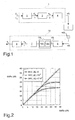
- FIG. 1 shows the equivalent base-band scheme of a pass-band packet transmission and reception system of signals with a single carrier.
- the M-DPSK modulator 1 comprises an M-PSK bit mapper 2 where M is the modulation order, i.e. the number of possible constellation symbols.
- the receiver retrieves the transmitted data using the phase difference between consecutive samples without needing to retrieve the phase offset introduced by the channel and the phase offset between transmitter and receiver on the carrier frequency.
- the signal at the output of the channel 5 still has a PSK structure
- noise is added to the signal s ( t ), preferably an additive white Gaussian noise w ( t ) (AWGN) having a null average with double-sided spectral power density of N 0 /2.
- AWGN additive white Gaussian noise w ( t )
- the sampled signal r k is processed by a M-DPSK differential demodulator module 7 and sent to an inverted bit mapper 8 providing decisions on the received bits q i .
- the demodulator multiplies the sampled signal r k by its delayed and conjugated version r k - 1 * .
- the useful term i.e. the term G 2 ⁇ a k ⁇ a k - 1 * ⁇ e j ⁇ 2 ⁇ ⁇ ⁇ ⁇ ⁇ fT is insensitive to the phase offset and, if ⁇ f n is sufficiently small, the frequency offset may be neglicted.
- the disadvantage of such a differential demodulator is due to the fact that the term bonded to the noise is amplified.
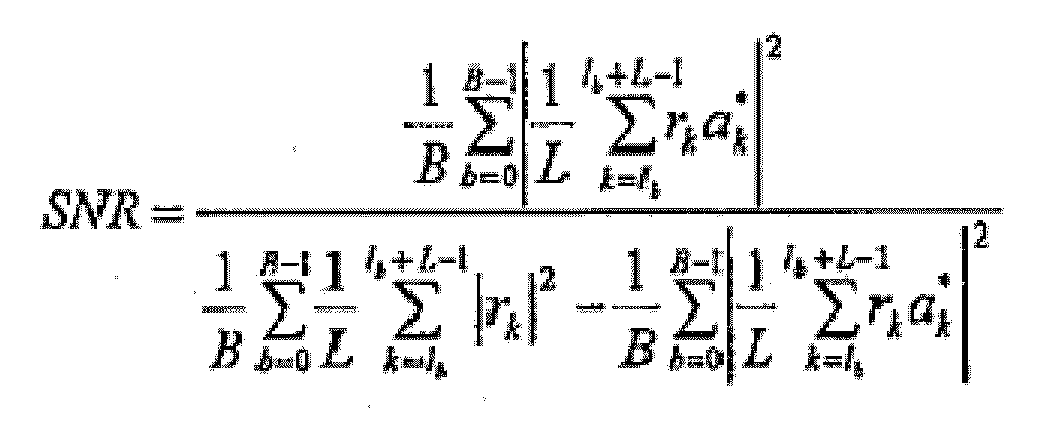
- the SNR estimators considered in this invention act on the signal r ( t ) at the input of the M-DPSK block 7 of the receiver.
- SNR
- 1 N ⁇ k l l + N - 1 r k ⁇ a k *
- 1 L ⁇ k l b l b + L - 1 r k ⁇ a k *
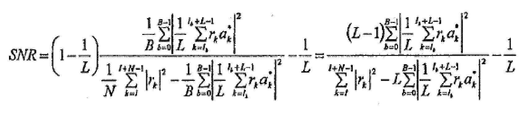
- the SNR ratio comprises a weighting factor 1-1/ L to weight the signal-to-noise ratio and a corrective term -1/ L , it is noted that, if L is sufficiently great, the weighting factor (1-1/ L ) and the corrective term -1/ L may be ignored, thus recovering the equation of the first embodiment of the estimator. In some cases, the corrective term -1/ L alone may be ignored.
- Figure 6 shows a graph of the estimated signal-to noise ratio SNRs versus the exact value SNRe over values of ⁇ f n being 2 ⁇ 10 -3 with values of B being 2, 4, 8 and respective values of L being 16, 8, 4 of the SNR estimator in accordance with the first and second embodiments
- Figure 7 shows a graph of the mean square error MSE versus the value SNRe over values of ⁇ f n being 2 ⁇ 10 -3 with values of B being 2, 4, 8 and respective values of L being 16, 8, 4 of the SNR estimator 100 in accordance with the first and second embodiments; the estimator in accordance with the first embodiment is indicated as SNVS ( B , L ), whereas that in accordance with the second embodiment is indicated as RSNVS( B , L ). From the values of Figures 6 and 7 , the improvement of the RSNVS estimator performances is apparent as compared to the SNVS with low values of L.
- 1 L ⁇ k l b l b + L - 1 r k ⁇ a k *
- 1 L ⁇ k l b l b + L - 1 r k ⁇ a k *
- the SNR estimator 100 in accordance with the preceding embodiments may also be used for multiple carrier systems, such as the OFDM (Orthogonal Frequency Division Multiplexing) systems.
- OFDM Orthogonal Frequency Division Multiplexing
- the phenomena responsible for the progressive phase shifting of the received constellation include: the carrier frequency offset, the packet synchronization offset and the sampling frequency offset.
- the carrier frequency offset in a pass-band system, produces a phase shifting of the constellation being constant on all the subcarriers of an OFDM symbol but increasing over time for every received OFDM symbol.
- the packet synchronization offset produces a rotation proportional to the subcarrier index, however remaining constant over all the symbols of the packet.
- the sampling frequency offset produces a rotation of the received constellation being different according to both the subcarrier index and the received OFDM symbol.
- a "data aided" SNR estimator may be implemented in different ways, based on the negative effect to be minimized. Specifically, an SNR estimator may act on the frequency in the various carriers or over time between the different transmitted OFDM symbols. However, in any case, the known transmitted sequence of length N and the N received samples may be divided in accordance with the invention in order to reduce the negative effect of the rotation of the constellation in estimating the value of SNR.
- N the known transmitted sequence of length N and the N received samples
- the known transmitted sequence of length N and the N received samples may be divided in accordance with the invention in order to reduce the negative effect of the rotation of the constellation in estimating the value of SNR.
- the M-PSK modulator 200 comprises a serial-to-parallel converter followed by a map which transforms a sequence of log 2 M bit c i into corresponding constellation points, a l ⁇
- the obtained signals are at the input of a channel 205 with a transfer function G ( f ) .
- the OFDM systems allow the signal band to be divided into sub-bands in which the transfer function of the channel G ( f ) may be approximated as almost flat. Under these conditions, the estimator in accordance with the present invention may independently be applied to every OFDM subcarrier.
- r n , h a n , h ⁇ G n ⁇ sinc N FFT ⁇ ⁇ f ⁇ N FFT F ⁇ e j ⁇ ⁇ ⁇ ⁇ f F ⁇ N FFT - 1 N FFT + I n , h + W n , h
- the samples r n,0 ... r n ,N FFT-1 are at the input of the SNR estimators 100 and then at the input of the M-DPSK receivers 208, parallel-to-serial converter 209, inverted mapper 210 in order to have the estimated bits m i corresponding to the bits c i at the output.
- the SNR estimator is applied at the input of the differential demodulator: if the SNR estimator is applied at the output of the differential demodulator there is a greater insensitivity to the frequency offset, the disadvantage being the noise amplification.
Landscapes
- Engineering & Computer Science (AREA)
- Computer Networks & Wireless Communication (AREA)
- Signal Processing (AREA)
- Quality & Reliability (AREA)
- Physics & Mathematics (AREA)
- Electromagnetism (AREA)
- Digital Transmission Methods That Use Modulated Carrier Waves (AREA)
Claims (11)
- Verfahren zum Abschätzen des Störabstandes für ein Paket-Ausendungs- und Empfangssystem von Signalen mit einer bekannten Datensequenz mittels einer M-DPSK-Modulation mit mindestens einem Träger,
wobei das System eine Einrichtung zur Paketübermittlung eines Signals mit einer Sequenz aus N bekannten Symbolen umfasst, wobei N eine positive ganze Zahl ist,
wobei die Übertragung eine M-DPSK-Modulation (1) des zu übertragenden Signals mittels eines M-PSK-Mappers (2) sowie eines Differentialblockes (3), die Übertragung des M-DPSK-modulierten Signals (s(t)) über einen Kanal (5), der einen konstanten Gewinn aufweist über alle N Symbole und in Gegenwart von Rauschen (w(t)) mit einem Durchschnittswert Null, und den Empfang des Signals (r(t)) an dem Ausgang des Kanals umfaßt,
wobei das Verfahren die Abschätzung des Störabstandes des empfangenen Signals mit der Aufteilung der N bekannten Symbole und von N Abtastwerten des Signals (r(t)) an dem Ausgang des Kanals in B Blöcke der Länge L umfasst, wobei B und L positive ganze Zahlen sind und B größer als 1 ist, und wobei B ausgedrückt wird durch
wobei O den Überlappungsfaktor aufeinanderfolgender Blöcke anzeigt, welche die Länge L haben und wobei die Abschätzung des Rauschabstandes gewonnen wird mittels der Gleichung
wobei lb = b(L-O) + 1 gilt,
wobei I der Index ist, der die Position des ersten bekannten Symbols aus der Sequenz der Länge N in dem Paket bezeichnet,
wobei rk der Abtastwert des empfangenen Signals an dem Ausgang des Kanals entsprechend dem bekannten übertragenen Symbol ist,
wobei ak das M-DPSK-modulierte bekannte übertragene Symbol ist,
ak' der komplex-konjugierte Wert des M-DPSK-modulierten bekannten übertragenen Symbols ist, und
wobei SNR die Abschätzung des Rauschabstandes angibt. - Verfahren nach Anspruch 1, dadurch gekennzeichnet, dass die B Blöcke ausgedrückt werden durch

wenn O = 0 gilt, und
dass die Abschätzung des Rauschabstandes gegeben ist durch:
- Verfahren nach Anspruch 1, dadurch gekennzeichnet, dass die Abschätzung des Rauschabstandes gegeben ist durch:
falls die Länge L des Blockes B hinreichend groß ist, um das Rauschen auszumitteln. - Verfahren nach Anspruch 1, dadurch gekennzeichnet, dass das Aussendungs- und Empfangssystem vom Bandpaß-Typ ist und dass der Empfänger von dem nicht-kohärenten Typ mit Differentialdemodulation ist, wobei die Abschätzung des Rauschabstandes vor der Differentialdemodulation des Signals bewirkt wird.
- Verfahren nach irgendeinem der vorstehenden Ansprüche, dadurch gekennzeichnet, dass das Aussendungs- und Empfangssystem vom Mehrfachträger-Typ ist.
- Vorrichtung zum Abschätzen des Rauschabstandes zum Gebrauch in einem Paket-Aussendungs- und Empfangssystem für Signale mit einer bekannten Datensequenz mittels einer M-DPSK-Modulation mit mindestens einem Träger,
wobei das System eine Einrichtung für die Paket-Aussendung eines Signals mit einer Sequenz aus N bekannten Symbolen aufweist, wobei N eine positive ganze Zahl ist,
wobei die Aussendungseinrichtung einen M-DPSK-Modulator (1) des zu sendenden Signals mit einem M-PSK-Mapper (2) sowie einem Differentialblock (3) umfaßt,
wobei das M-DPSK-modulierte Signal (s(t)) angepasst ist, durch einen Kanal (5) hindurchzulaufen, welcher einen konstanten Gewinn aufweist über alle N Symbole und in Gegenwart von Rauschen (w(t)) mit dem Durchschnittswert Null,
wobei das System eine Einrichtung (10) zum Empfangen des Signals (r(t)) an dem Ausgang des Kanals umfasst,
wobei die Vorrichtung eine erste Einrichtung (101) aufweist, welche eingerichtet ist zum Aufteilen der N bekannten Symbole und der N Abtastwerte des Signals (r(t)) an dem Ausgang des Kanals in B Blöcke einer Länge L, wobei B und L positive ganze Zahlen sind und B größer als 1 ist, und
wobei die erste Einrichtung (101) eingerichtet ist, aufeinanderfolgende Blöcke mit einer Länge L mit einem Faktor O zu überlappen, wobei B ausgedrückt wird durch
wobei O den Überlappungsfaktor aufeinanderfolgender Blöcke mit einer Länge L anzeigt, und
wobei die Vorrichtung eine zweite Einrichtung (102) aufweist, die eingerichtet ist zum Abschätzen des Rauschabstandes mittels der Gleichung:
wobei gilt lb = (L-O) b+I,
wobei I der Index ist, der die Position des ersten bekannten Symbols der Sequenz der Länge L in dem Paket bezeichnet,
wobei rk der Abtastwert des empfangenen Signals an dem Ausgang des Kanals entsprechend dem bekannten Symbol ist,
wobei ak das M-DPSK-modulierte bekannte übertragene Symbol ist,
wobei ak der komplex-konjugierte Wert des M-DPSK-modulierten bekannten übertragenen Symbols ist und
wobei SNR die Abschätzung des Rauschabstandes angibt. - Vorrichtung nach Anspruch 6, dadurch gekennzeichnet, dass gilt O = 0 und dass die zweite Einrichtung (102) eingerichtet ist zum Bewirken der Abschätzung des Rauschabstandes durch die Gleichung:
- Vorrichtung nach Anspruch 6, dadurch gekennzeichnet, dass die zweiten Einrichtung (102) eingerichtet ist zum Berechnen der Abschätzung des Rauschabstandes durch die Gleichung

wenn die Länge L des Blockes B hinreichend groß ist, um das Rauschen auszumitteln. - Vorrichtung nach Anspruch 6, dadurch gekennzeichnet, dass das Aussendungs- und Empfangssystem vom Bandpass-Typ ist,
wobei die Empfangseinrichtung (10) des Signals einen nicht-kohärenten Empfang bewirkt und einen Differentialdemodulator (7) umfasst,
wobei wobei die Abschätzungsvorrichtung eingerichtet ist, die Abschätzung des Rauschabstandes des Signals an dem Eingang des Differential-Demodulators zu berechnen. - Vorrichtung nach irgendeinem der Ansprüche 6 bis 9, dadurch gekennzeichnet, dass das Aussendungs- und Empfangs-System vom Mehrfachträger-Typ ist.
- Paketaussendungs- und Empfangssystem von Signalen mit einer bekannten Datensequenz mittels einer M-DPSK-Modulation mit mindestens einem Träger,
wobei das System eine Einrichtung zur Paketaussendung eines Signals mit einer Sequenz von N bekannten Symbolen aufweist, wobei N eine positive ganze Zahl ist, wobei die Übertragungseinrichtung einen M-DPSK-Modulator (1) des zu übertragenden Signals umfasst, der einen M-PSK-Mapper (2) und einen Differentialblock (3) umfasst,
wobei das M-DPSK-modulierte Signal (s(t)) eingerichtet ist, einen Kanal (5) mit konstanten Gewinn über alle N-Symbole und in Gegenwart von Rauschen (w(t)) einem Durchschnittswert Null zu durchzulaufen,
wobei das System eine Einrichtung (10) zum Empfangen des Signals (r(t)) an dem Ausgang des Kanals aufweist, der einen Differentialdemodulator (7) umfasst, und eine Vorrichtung, die in irgendeinem der Ansprüche 6 bis 10 bestimmt und angepasst ist zum Bewirken der Abschätzung des Rauschabstandes des Signals an dem Eingang des Differentialdemodulators (7).
Applications Claiming Priority (1)
| Application Number | Priority Date | Filing Date | Title |
|---|---|---|---|
| ITMI20082304 | 2008-12-23 |
Publications (2)
| Publication Number | Publication Date |
|---|---|
| EP2202906A1 EP2202906A1 (de) | 2010-06-30 |
| EP2202906B1 true EP2202906B1 (de) | 2015-05-20 |
Family
ID=41227241
Family Applications (1)
| Application Number | Title | Priority Date | Filing Date |
|---|---|---|---|
| EP20090180214 Active EP2202906B1 (de) | 2008-12-23 | 2009-12-21 | Datenunterstützte Schätzung des Signal-Rausch-Verhältnisses für M-DPSK-Modulationssysteme mit Aufteilung der empfangenen Abtastwerte in Blöcken |
Country Status (2)
| Country | Link |
|---|---|
| US (1) | US8363760B2 (de) |
| EP (1) | EP2202906B1 (de) |
Families Citing this family (3)
| Publication number | Priority date | Publication date | Assignee | Title |
|---|---|---|---|---|
| US8265203B2 (en) * | 2009-01-21 | 2012-09-11 | Ntt Docomo, Inc. | Method and system of differential complex and real multi-carrier demodulation |
| EP2280510B1 (de) * | 2009-07-09 | 2016-05-04 | STMicroelectronics S.r.l. | Verfahren zum Bestimmen eines Rahmensynchronisierungsmusters oder eines Einzelwortes in einem empfangenen digitalen Signal |
| WO2018074393A1 (ja) * | 2016-10-19 | 2018-04-26 | 日本電気株式会社 | 通信装置、通信システム、および通信方法 |
Family Cites Families (3)
| Publication number | Priority date | Publication date | Assignee | Title |
|---|---|---|---|---|
| US7356071B2 (en) * | 2005-05-06 | 2008-04-08 | Interdigital Technology Corporation | Method and apparatus for estimating signal-to-noise ratio based on dedicated physical channel pilot symbols |
| US20070002980A1 (en) * | 2005-06-29 | 2007-01-04 | Eyal Krupka | Method for timing and sequence hypotheses selection |
| KR100930720B1 (ko) * | 2007-11-29 | 2009-12-09 | 한국전자통신연구원 | 신호대잡음비 추정 장치 및 방법 |
-
2009
- 2009-12-21 EP EP20090180214 patent/EP2202906B1/de active Active
- 2009-12-23 US US12/646,348 patent/US8363760B2/en active Active
Also Published As
| Publication number | Publication date |
|---|---|
| EP2202906A1 (de) | 2010-06-30 |
| US20100166101A1 (en) | 2010-07-01 |
| US8363760B2 (en) | 2013-01-29 |
Similar Documents
| Publication | Publication Date | Title |
|---|---|---|
| EP1028564B1 (de) | Schätzung von Träger- und Abtastungsfrequenzverschiebungen in Mehrträgerempfängern | |
| US7308034B2 (en) | Method and device for tracking carrier frequency offset and sampling frequency offset in orthogonal frequency division multiplexing wireless communication system | |
| US7139321B2 (en) | Channel estimation for wireless OFDM systems | |
| EP1072138B1 (de) | Verfahren und einrichtung zur feinen frequenzsynchronisierung in mehrträgerdemodulationssystemen | |
| US20030156534A1 (en) | Communication system using OFDM | |
| EP1894378B1 (de) | Empfängergerät für den Empfang eines Mehrträgersignals | |
| US20040120412A1 (en) | Carrier frequency offset estimation in a wireless communication system | |
| US6584164B1 (en) | Method for forming a training sequence | |
| US7684501B2 (en) | Apparatus and method for carrier frequency offset and phase compensation in communication system | |
| US7702024B2 (en) | Sampling frequency offset estimation apparatus and method for OFDM system | |
| JP3429746B2 (ja) | マルチキャリア復調システムにおけるエコー位相オフセット補正 | |
| EP0838928B1 (de) | Entzerrung von Mehrträgersignalen | |
| US6961393B1 (en) | In-band-on-channel (IBOC) system and methods of operation using orthogonal frequency division multiplexing (OFDM) with timing and frequency offset correction | |
| US20040032909A1 (en) | Reference symbol multicarrier signal designed to limit intersymbol interference | |
| EP1924045B1 (de) | OFDM mit limitierter Bandbreite | |
| US8433014B2 (en) | Receiving apparatus and receiving method | |
| US8379780B2 (en) | Method for compensation of information losses in an OFDM-based multi-carrier communication signal caused by blanking out pulse-shaped interferences | |
| EP2202906B1 (de) | Datenunterstützte Schätzung des Signal-Rausch-Verhältnisses für M-DPSK-Modulationssysteme mit Aufteilung der empfangenen Abtastwerte in Blöcken | |
| US8743946B2 (en) | Frequency-domain equalization and combining for single carrier transmission | |
| US20080266014A1 (en) | On-off keying - 7-phase shift keying modulation system and method for fiber communication | |
| KR100429837B1 (ko) | 직교주파수 분할 다중화 신호의 동기화 방법 및 그 장치 | |
| CN109688081A (zh) | 一种基于tetraⅱ标准的信号频偏估计方法、无线通信系统 | |
| US7515657B1 (en) | Frequency tracking for OFDM transmission over frequency selective channels | |
| US8223865B2 (en) | Method for the blind estimation of OFDM signal parameters by adapted filtering | |
| WO2008082117A1 (en) | Method and apparatus for estimating carrier to interference and noise ratio |
Legal Events
| Date | Code | Title | Description |
|---|---|---|---|
| PUAI | Public reference made under article 153(3) epc to a published international application that has entered the european phase |
Free format text: ORIGINAL CODE: 0009012 |
|
| AK | Designated contracting states |
Kind code of ref document: A1 Designated state(s): AT BE BG CH CY CZ DE DK EE ES FI FR GB GR HR HU IE IS IT LI LT LU LV MC MK MT NL NO PL PT RO SE SI SK SM TR |
|
| 17P | Request for examination filed |
Effective date: 20101210 |
|
| GRAP | Despatch of communication of intention to grant a patent |
Free format text: ORIGINAL CODE: EPIDOSNIGR1 |
|
| RIC1 | Information provided on ipc code assigned before grant |
Ipc: H04L 1/20 20060101AFI20141117BHEP Ipc: H04B 17/00 20060101ALI20141117BHEP Ipc: H04L 27/233 20060101ALI20141117BHEP |
|
| INTG | Intention to grant announced |
Effective date: 20141211 |
|
| GRAS | Grant fee paid |
Free format text: ORIGINAL CODE: EPIDOSNIGR3 |
|
| GRAA | (expected) grant |
Free format text: ORIGINAL CODE: 0009210 |
|
| AK | Designated contracting states |
Kind code of ref document: B1 Designated state(s): AT BE BG CH CY CZ DE DK EE ES FI FR GB GR HR HU IE IS IT LI LT LU LV MC MK MT NL NO PL PT RO SE SI SK SM TR |
|
| RAP1 | Party data changed (applicant data changed or rights of an application transferred) |
Owner name: STMICROELECTRONICS S.R.L. |
|
| REG | Reference to a national code |
Ref country code: GB Ref legal event code: FG4D |
|
| REG | Reference to a national code |
Ref country code: CH Ref legal event code: EP |
|
| REG | Reference to a national code |
Ref country code: AT Ref legal event code: REF Ref document number: 728217 Country of ref document: AT Kind code of ref document: T Effective date: 20150615 |
|
| REG | Reference to a national code |
Ref country code: IE Ref legal event code: FG4D |
|
| REG | Reference to a national code |
Ref country code: DE Ref legal event code: R096 Ref document number: 602009031295 Country of ref document: DE |
|
| REG | Reference to a national code |
Ref country code: AT Ref legal event code: MK05 Ref document number: 728217 Country of ref document: AT Kind code of ref document: T Effective date: 20150520 |
|
| REG | Reference to a national code |
Ref country code: LT Ref legal event code: MG4D |
|
| REG | Reference to a national code |
Ref country code: NL Ref legal event code: MP Effective date: 20150520 |
|
| PG25 | Lapsed in a contracting state [announced via postgrant information from national office to epo] |
Ref country code: ES Free format text: LAPSE BECAUSE OF FAILURE TO SUBMIT A TRANSLATION OF THE DESCRIPTION OR TO PAY THE FEE WITHIN THE PRESCRIBED TIME-LIMIT Effective date: 20150520 Ref country code: PT Free format text: LAPSE BECAUSE OF FAILURE TO SUBMIT A TRANSLATION OF THE DESCRIPTION OR TO PAY THE FEE WITHIN THE PRESCRIBED TIME-LIMIT Effective date: 20150921 Ref country code: LT Free format text: LAPSE BECAUSE OF FAILURE TO SUBMIT A TRANSLATION OF THE DESCRIPTION OR TO PAY THE FEE WITHIN THE PRESCRIBED TIME-LIMIT Effective date: 20150520 Ref country code: NO Free format text: LAPSE BECAUSE OF FAILURE TO SUBMIT A TRANSLATION OF THE DESCRIPTION OR TO PAY THE FEE WITHIN THE PRESCRIBED TIME-LIMIT Effective date: 20150820 Ref country code: HR Free format text: LAPSE BECAUSE OF FAILURE TO SUBMIT A TRANSLATION OF THE DESCRIPTION OR TO PAY THE FEE WITHIN THE PRESCRIBED TIME-LIMIT Effective date: 20150520 Ref country code: FI Free format text: LAPSE BECAUSE OF FAILURE TO SUBMIT A TRANSLATION OF THE DESCRIPTION OR TO PAY THE FEE WITHIN THE PRESCRIBED TIME-LIMIT Effective date: 20150520 |
|
| PG25 | Lapsed in a contracting state [announced via postgrant information from national office to epo] |
Ref country code: IS Free format text: LAPSE BECAUSE OF FAILURE TO SUBMIT A TRANSLATION OF THE DESCRIPTION OR TO PAY THE FEE WITHIN THE PRESCRIBED TIME-LIMIT Effective date: 20150920 Ref country code: BG Free format text: LAPSE BECAUSE OF FAILURE TO SUBMIT A TRANSLATION OF THE DESCRIPTION OR TO PAY THE FEE WITHIN THE PRESCRIBED TIME-LIMIT Effective date: 20150820 Ref country code: AT Free format text: LAPSE BECAUSE OF FAILURE TO SUBMIT A TRANSLATION OF THE DESCRIPTION OR TO PAY THE FEE WITHIN THE PRESCRIBED TIME-LIMIT Effective date: 20150520 Ref country code: GR Free format text: LAPSE BECAUSE OF FAILURE TO SUBMIT A TRANSLATION OF THE DESCRIPTION OR TO PAY THE FEE WITHIN THE PRESCRIBED TIME-LIMIT Effective date: 20150821 Ref country code: LV Free format text: LAPSE BECAUSE OF FAILURE TO SUBMIT A TRANSLATION OF THE DESCRIPTION OR TO PAY THE FEE WITHIN THE PRESCRIBED TIME-LIMIT Effective date: 20150520 |
|
| PG25 | Lapsed in a contracting state [announced via postgrant information from national office to epo] |
Ref country code: DK Free format text: LAPSE BECAUSE OF FAILURE TO SUBMIT A TRANSLATION OF THE DESCRIPTION OR TO PAY THE FEE WITHIN THE PRESCRIBED TIME-LIMIT Effective date: 20150520 Ref country code: EE Free format text: LAPSE BECAUSE OF FAILURE TO SUBMIT A TRANSLATION OF THE DESCRIPTION OR TO PAY THE FEE WITHIN THE PRESCRIBED TIME-LIMIT Effective date: 20150520 |
|
| REG | Reference to a national code |
Ref country code: DE Ref legal event code: R097 Ref document number: 602009031295 Country of ref document: DE |
|
| PG25 | Lapsed in a contracting state [announced via postgrant information from national office to epo] |
Ref country code: SK Free format text: LAPSE BECAUSE OF FAILURE TO SUBMIT A TRANSLATION OF THE DESCRIPTION OR TO PAY THE FEE WITHIN THE PRESCRIBED TIME-LIMIT Effective date: 20150520 Ref country code: CZ Free format text: LAPSE BECAUSE OF FAILURE TO SUBMIT A TRANSLATION OF THE DESCRIPTION OR TO PAY THE FEE WITHIN THE PRESCRIBED TIME-LIMIT Effective date: 20150520 Ref country code: RO Free format text: LAPSE BECAUSE OF NON-PAYMENT OF DUE FEES Effective date: 20150520 Ref country code: PL Free format text: LAPSE BECAUSE OF FAILURE TO SUBMIT A TRANSLATION OF THE DESCRIPTION OR TO PAY THE FEE WITHIN THE PRESCRIBED TIME-LIMIT Effective date: 20150520 |
|
| PLBE | No opposition filed within time limit |
Free format text: ORIGINAL CODE: 0009261 |
|
| STAA | Information on the status of an ep patent application or granted ep patent |
Free format text: STATUS: NO OPPOSITION FILED WITHIN TIME LIMIT |
|
| 26N | No opposition filed |
Effective date: 20160223 |
|
| PG25 | Lapsed in a contracting state [announced via postgrant information from national office to epo] |
Ref country code: BE Free format text: LAPSE BECAUSE OF NON-PAYMENT OF DUE FEES Effective date: 20151231 Ref country code: SI Free format text: LAPSE BECAUSE OF FAILURE TO SUBMIT A TRANSLATION OF THE DESCRIPTION OR TO PAY THE FEE WITHIN THE PRESCRIBED TIME-LIMIT Effective date: 20150520 |
|
| PG25 | Lapsed in a contracting state [announced via postgrant information from national office to epo] |
Ref country code: LU Free format text: LAPSE BECAUSE OF FAILURE TO SUBMIT A TRANSLATION OF THE DESCRIPTION OR TO PAY THE FEE WITHIN THE PRESCRIBED TIME-LIMIT Effective date: 20151221 Ref country code: MC Free format text: LAPSE BECAUSE OF FAILURE TO SUBMIT A TRANSLATION OF THE DESCRIPTION OR TO PAY THE FEE WITHIN THE PRESCRIBED TIME-LIMIT Effective date: 20150520 |
|
| REG | Reference to a national code |
Ref country code: CH Ref legal event code: PL |
|
| GBPC | Gb: european patent ceased through non-payment of renewal fee |
Effective date: 20151221 |
|
| PG25 | Lapsed in a contracting state [announced via postgrant information from national office to epo] |
Ref country code: BE Free format text: LAPSE BECAUSE OF FAILURE TO SUBMIT A TRANSLATION OF THE DESCRIPTION OR TO PAY THE FEE WITHIN THE PRESCRIBED TIME-LIMIT Effective date: 20150520 |
|
| REG | Reference to a national code |
Ref country code: IE Ref legal event code: MM4A |
|
| REG | Reference to a national code |
Ref country code: FR Ref legal event code: ST Effective date: 20160831 |
|
| PG25 | Lapsed in a contracting state [announced via postgrant information from national office to epo] |
Ref country code: CH Free format text: LAPSE BECAUSE OF NON-PAYMENT OF DUE FEES Effective date: 20151231 Ref country code: GB Free format text: LAPSE BECAUSE OF NON-PAYMENT OF DUE FEES Effective date: 20151221 Ref country code: LI Free format text: LAPSE BECAUSE OF NON-PAYMENT OF DUE FEES Effective date: 20151231 Ref country code: IE Free format text: LAPSE BECAUSE OF NON-PAYMENT OF DUE FEES Effective date: 20151221 |
|
| PG25 | Lapsed in a contracting state [announced via postgrant information from national office to epo] |
Ref country code: FR Free format text: LAPSE BECAUSE OF NON-PAYMENT OF DUE FEES Effective date: 20151231 |
|
| PG25 | Lapsed in a contracting state [announced via postgrant information from national office to epo] |
Ref country code: HU Free format text: LAPSE BECAUSE OF FAILURE TO SUBMIT A TRANSLATION OF THE DESCRIPTION OR TO PAY THE FEE WITHIN THE PRESCRIBED TIME-LIMIT; INVALID AB INITIO Effective date: 20091221 Ref country code: SM Free format text: LAPSE BECAUSE OF FAILURE TO SUBMIT A TRANSLATION OF THE DESCRIPTION OR TO PAY THE FEE WITHIN THE PRESCRIBED TIME-LIMIT Effective date: 20150520 |
|
| PG25 | Lapsed in a contracting state [announced via postgrant information from national office to epo] |
Ref country code: SE Free format text: LAPSE BECAUSE OF FAILURE TO SUBMIT A TRANSLATION OF THE DESCRIPTION OR TO PAY THE FEE WITHIN THE PRESCRIBED TIME-LIMIT Effective date: 20150520 Ref country code: CY Free format text: LAPSE BECAUSE OF FAILURE TO SUBMIT A TRANSLATION OF THE DESCRIPTION OR TO PAY THE FEE WITHIN THE PRESCRIBED TIME-LIMIT Effective date: 20150520 Ref country code: NL Free format text: LAPSE BECAUSE OF FAILURE TO SUBMIT A TRANSLATION OF THE DESCRIPTION OR TO PAY THE FEE WITHIN THE PRESCRIBED TIME-LIMIT Effective date: 20150520 |
|
| PG25 | Lapsed in a contracting state [announced via postgrant information from national office to epo] |
Ref country code: TR Free format text: LAPSE BECAUSE OF FAILURE TO SUBMIT A TRANSLATION OF THE DESCRIPTION OR TO PAY THE FEE WITHIN THE PRESCRIBED TIME-LIMIT Effective date: 20150520 Ref country code: MT Free format text: LAPSE BECAUSE OF FAILURE TO SUBMIT A TRANSLATION OF THE DESCRIPTION OR TO PAY THE FEE WITHIN THE PRESCRIBED TIME-LIMIT Effective date: 20150520 |
|
| PG25 | Lapsed in a contracting state [announced via postgrant information from national office to epo] |
Ref country code: MK Free format text: LAPSE BECAUSE OF FAILURE TO SUBMIT A TRANSLATION OF THE DESCRIPTION OR TO PAY THE FEE WITHIN THE PRESCRIBED TIME-LIMIT Effective date: 20150520 |
|
| PGFP | Annual fee paid to national office [announced via postgrant information from national office to epo] |
Ref country code: DE Payment date: 20251126 Year of fee payment: 17 |
|
| PGFP | Annual fee paid to national office [announced via postgrant information from national office to epo] |
Ref country code: IT Payment date: 20251119 Year of fee payment: 17 |