EP2202904B1 - Relaisstation und Dekodierer - Google Patents
Relaisstation und Dekodierer Download PDFInfo
- Publication number
- EP2202904B1 EP2202904B1 EP20080022422 EP08022422A EP2202904B1 EP 2202904 B1 EP2202904 B1 EP 2202904B1 EP 20080022422 EP20080022422 EP 20080022422 EP 08022422 A EP08022422 A EP 08022422A EP 2202904 B1 EP2202904 B1 EP 2202904B1
- Authority
- EP
- European Patent Office
- Prior art keywords
- information
- soft
- soft information
- codeword
- decoder
- Prior art date
- Legal status (The legal status is an assumption and is not a legal conclusion. Google has not performed a legal analysis and makes no representation as to the accuracy of the status listed.)
- Active
Links
- 238000013139 quantization Methods 0.000 claims description 60
- 230000005540 biological transmission Effects 0.000 claims description 36
- 238000000034 method Methods 0.000 claims description 30
- 238000010295 mobile communication Methods 0.000 claims description 9
- 230000003044 adaptive effect Effects 0.000 claims description 6
- 238000004590 computer program Methods 0.000 claims description 5
- 125000004122 cyclic group Chemical group 0.000 claims description 4
- 230000001413 cellular effect Effects 0.000 claims description 2
- 238000004088 simulation Methods 0.000 description 27
- 238000005562 fading Methods 0.000 description 20
- 238000013461 design Methods 0.000 description 16
- 230000033590 base-excision repair Effects 0.000 description 15
- 238000004422 calculation algorithm Methods 0.000 description 15
- 238000009826 distribution Methods 0.000 description 13
- 238000004891 communication Methods 0.000 description 12
- 230000008901 benefit Effects 0.000 description 10
- 238000001514 detection method Methods 0.000 description 10
- 238000013459 approach Methods 0.000 description 9
- 238000012545 processing Methods 0.000 description 8
- 230000014509 gene expression Effects 0.000 description 7
- 238000005457 optimization Methods 0.000 description 6
- 230000007246 mechanism Effects 0.000 description 5
- 230000003321 amplification Effects 0.000 description 4
- 238000009795 derivation Methods 0.000 description 4
- 230000000694 effects Effects 0.000 description 4
- 238000013507 mapping Methods 0.000 description 4
- 238000003199 nucleic acid amplification method Methods 0.000 description 4
- 239000000654 additive Substances 0.000 description 3
- 230000000996 additive effect Effects 0.000 description 3
- 230000015556 catabolic process Effects 0.000 description 3
- 238000006731 degradation reaction Methods 0.000 description 3
- 230000001934 delay Effects 0.000 description 3
- 230000008569 process Effects 0.000 description 3
- 230000011664 signaling Effects 0.000 description 3
- 238000012546 transfer Methods 0.000 description 3
- 230000001419 dependent effect Effects 0.000 description 2
- 238000009472 formulation Methods 0.000 description 2
- 238000011835 investigation Methods 0.000 description 2
- 238000012804 iterative process Methods 0.000 description 2
- 230000007774 longterm Effects 0.000 description 2
- 239000000203 mixture Substances 0.000 description 2
- 235000008694 Humulus lupulus Nutrition 0.000 description 1
- 238000004458 analytical method Methods 0.000 description 1
- 230000009286 beneficial effect Effects 0.000 description 1
- 238000007906 compression Methods 0.000 description 1
- 230000006835 compression Effects 0.000 description 1
- 238000012937 correction Methods 0.000 description 1
- 230000008878 coupling Effects 0.000 description 1
- 238000010168 coupling process Methods 0.000 description 1
- 238000005859 coupling reaction Methods 0.000 description 1
- 230000007423 decrease Effects 0.000 description 1
- 230000001627 detrimental effect Effects 0.000 description 1
- 238000010586 diagram Methods 0.000 description 1
- 230000010354 integration Effects 0.000 description 1
- 230000006855 networking Effects 0.000 description 1
Images


Classifications
-
- H—ELECTRICITY
- H04—ELECTRIC COMMUNICATION TECHNIQUE
- H04L—TRANSMISSION OF DIGITAL INFORMATION, e.g. TELEGRAPHIC COMMUNICATION
- H04L1/00—Arrangements for detecting or preventing errors in the information received
- H04L1/004—Arrangements for detecting or preventing errors in the information received by using forward error control
- H04L1/0045—Arrangements at the receiver end
- H04L1/0047—Decoding adapted to other signal detection operation
- H04L1/005—Iterative decoding, including iteration between signal detection and decoding operation
-
- H—ELECTRICITY
- H04—ELECTRIC COMMUNICATION TECHNIQUE
- H04B—TRANSMISSION
- H04B7/00—Radio transmission systems, i.e. using radiation field
- H04B7/14—Relay systems
- H04B7/15—Active relay systems
- H04B7/155—Ground-based stations
-
- H—ELECTRICITY
- H04—ELECTRIC COMMUNICATION TECHNIQUE
- H04L—TRANSMISSION OF DIGITAL INFORMATION, e.g. TELEGRAPHIC COMMUNICATION
- H04L25/00—Baseband systems
- H04L25/02—Details ; arrangements for supplying electrical power along data transmission lines
- H04L25/06—Dc level restoring means; Bias distortion correction ; Decision circuits providing symbol by symbol detection
- H04L25/067—Dc level restoring means; Bias distortion correction ; Decision circuits providing symbol by symbol detection providing soft decisions, i.e. decisions together with an estimate of reliability
-
- H—ELECTRICITY
- H04—ELECTRIC COMMUNICATION TECHNIQUE
- H04B—TRANSMISSION
- H04B7/00—Radio transmission systems, i.e. using radiation field
- H04B7/14—Relay systems
- H04B7/15—Active relay systems
- H04B7/155—Ground-based stations
- H04B7/15592—Adapting at the relay station communication parameters for supporting cooperative relaying, i.e. transmission of the same data via direct - and relayed path
-
- H—ELECTRICITY
- H04—ELECTRIC COMMUNICATION TECHNIQUE
- H04L—TRANSMISSION OF DIGITAL INFORMATION, e.g. TELEGRAPHIC COMMUNICATION
- H04L1/00—Arrangements for detecting or preventing errors in the information received
- H04L2001/0092—Error control systems characterised by the topology of the transmission link
- H04L2001/0097—Relays
Definitions
- the present invention is in the field of wireless communication in a mobile communication system using relay stations.
- Conventional relaying concepts comprise, for example, standard relaying methods as amplify-and-forward relaying, decode-and-forward relaying, respectively. While amplify-and-forward relaying has low delay on the expense of noise amplification, decode-and-forward relaying causes a processing delay at the relay station, due to decoding. Moreover, decoding errors at the relay station may have detrimental effects on decoding at the destination.
- the designated purpose of a relay station in wireless networks is to facilitate the transmission of other users within the same cell, where one important benefit is provision of cooperative diversity as shown by A. Sendonaris, E. Erkip, and B. Aazhang, "Increasing uplink capacity via user cooperation diversity,” in Proc. IEEE Int. Symp. on Information Theory, 1998 . While the concept of network coding as shown by R. Ahlswede, N. Cai, S. R. Li, and R. W. Yeung, "Network information flow,” IEEE Trans. Inf. Theory, vol. 46, no. 4, pp. 1204-1216, Apr.
- Fig. 13 illustrates a scenario and a radio network which utilizes multi-hop relaying.
- Fig. 13 shows a source s 1 transmitting a symbol or a transmit word x 1 , which is received by a relay station r and a destination d.
- Fig. 13 shows a second source s 2 transmitting a second symbol or a transmit word x 2 , which is also received by the relay station r and a destination d.
- the relay station r transmits a symbol x r , which is also received by the destination.
- the network geometry is assumed to be such that the relay is closer to the destination than to the sources, so that the source-relay channel quality is too low to permit reliable decoding at the relay.
- the relay-destination link can support a higher rate due to its proximity to the destination.
- the relay can make use of ideas from network coding as described by R. Ahlswede, N. Cai, S. R. Li, and R. W. Yeung, "Network information flow," IEEE Trans. Inf. Theory, vol. 46, no. 4, pp.
- LLRs log-likelihood ratios
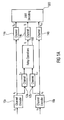
- Fig. 14 shows a first encoder 1410 coding an information word u 1 to a first symbol or transmit word x 1 , which is transmitted to a relay station 1450 and a destination 1470. Furthermore, Fig. 14 shows a second encoder 1420, which encodes a second information word u 2 to a second symbol or transmit word x 2 , which is also transmitted to the relay station 1450 and the destination 1470. As indicated in Fig. 14,
- the two decoders 1451 and 1452 decode the information words u 1 and u 2 .
- the two decoded information words are then combined as indicated by addition 1453 in Fig. 14 and the combination is encoded by the encoder 1454 shown in Fig. 14 .
- the encoded combined symbol x R is then transmitted from the relay station 1450 to the destination 1470, where it is superimposed by AWGN n B .
- Three symbols or receive words are received at the destination 1470, namely y 1 from "encoder 1" 1410, y 2 from “encoder 2" 1420, and y R from the relay station 1450.
- joint decoding may be utilized in order to decode the information words u 1 and u 2 .
- One disadvantage of the concept illustrated in Fig. 14 is the delay, which is associated with decoding the received signal at the relay station 1450 in order to derive the information words and with encoding the combination of said information words again at the relay station 1450.
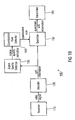
- Fig. 15 shows similar components as have been described with respect to Fig. 14 , however, at the relay station 1450, instead of combining the decoded information words u 1 and u 2 , a joint encoder 1455 is utilized.
- the joint encoder 1455 may have the advantage that an increased block length can be used, which may particularly be beneficial for iterative decoding.
- the joint encoder 1455 may enable increased diversity which may be exploited at the joint decoder at the destination 1470.
- high delays are still involved with decoding the received signals at the relay station and jointly encoding the decoded signals again, especially when increased block lengths are used.
- Another problem arises from decoding errors at the relay station 1450, which are re-encoded, and therewith extended or forwarded to the destination 1470.
- FIG. 16 shows similar components as have already been introduced with respect to Figs. 14 and 15 .
- Fig. 16 illustrates the approach of analog transmission from the relay station 1450 to the destination 1470, which may, for example, be implemented at a base station or a NodeB.
- LLR Log Likelihood Ratio
- the information word u may comprise only a single bit, which can take two values, namely +1 or -1.
- the so-called soft information can be determined by considering the quotient of the probability that the bit equals +1 and the probability that the bit equals -1, which is shown in the equation at the top of Fig. 16 .
- the decoders 1451 and 1452 determine the LLRs of the corresponding information words u 1 and u 2 .
- Fig. 16 shows that the relay station 1450, the LLRs at the output of the second decoder 1452 are provided to an interleaver 1456, which interleaves the LLRs.
- the interleaved LLRs from the second decoder are then combined by the combiner 1457 before analog transmission is used to transmit information on the combination to the destination 1470.
- Reliability information, in terms of the LLRs is therewith provided to the joint decoder at the destination 1470.
- long delays still occur at the relay station 1450 in order to determine the soft information by the two decoders 1451 and 1452.
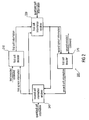
- Fig. 17 illustrates the same scenario as Fig. 16 , however, the details on the destination or NodeB are provided.
- LLRs are determined at the destination 1470 for the three receive signals y 1 , y 2 , and y R by the three detectors 1471, 1472, and 1473.
- Fig. 17 illustrates the concept of joint iterative decoding.
- the log likelihood ratio provided by the detector 1471 is, in a first step, provided to a first decoder 1475, in order to determine LLRs on the information word u 1 .
- the LLRs provided at the input of the decoder 1475 correspond to a-posteriori knowledge of the transmitted code words.
- a-priori knowledge on the information word u 1 is determined by evaluating the difference of the a-posteriori knowledge and the output of the decoder 1475.
- the a-priori knowledge is still available in terms of LLRs which can then be combined by the combiner 1476 with the LLRs determined by detector 1473 from the received signal y R on the combination determined at the relay station 1450.
- the combination can, for example, be determined by determining a combined LLR for an XOR-combination of the information words u 1 and u 2 . Subsequently, a derivation of the exact combination will be provided which is indicated by . From the a-priori knowledge on the first information word and the LLR on the combination, a-posteriori knowledge on the second information word can be determined, which is de-interleaved by de-interleaver 1477. The de-interleaver 1477 corresponds to the interleaver 1456 at the relay station 1450.
- the de-interleaved LLR at the output of the de-interleaver 1477 can then be combined with the LLRs detected by detector 1472 from the second receive signal y 2 , and provided as an input to the second decoder 1478.
- the second decoder 1478 then provides LLRs on the second information word u 2 at its output, from which the a-posteriori knowledge from the detector 1472 and the interleaver 1477 can be deducted for determining a-priori information, which may also be called extrinsic information.
- the interleaved LLRs can again be combined with the output of the detector 1473 by combiner 1480.
- A-posteriori information on the first information word u 1 is available at the output of the combiner 1480, which can again be combined with the a-posteriori knowledge at the output of the detector 1471.
- the above description corresponds to a first iteration loop of the joint iterative decoder, which is similar to the principle of turbo decoding. Multiple iteration loops may be carried out along the lines of the above description in order to determine more reliable information on the information words u 1 and u 2 .
- Fig. 18 illustrates the case, where at a relay station 1450 bad or weak radio channels are experienced and accordingly, LLRs are determined, which are equal or close to zero. Consequently, at the destination 1470, the LLRs determined by the detector 1473 equal zero, i.e. only very unreliable information is available. Consequently, the combinations carried out by combiners 1476 and 1480 also yield LLRs, which are zero. Therefore, within.the decoder, the LLRs of detector 1473 do not influence the LLRs determined by the detectors 1471 and 1472. In other words, if decoding at the relay station 1450 is very unreliable, decoding at the destination is solely based on the outputs of the detectors 1471 and 1472. The iterative process does not provide any benefits in this case.
- bit error rate Bit Error Rate
- two sources 1901 and 1902 transmit signals to a relay station 1903 and a destination 1904.
- SNR Signal-to-Noise Ratio
- SNR sr Signal-to-Noise Ratio
- a view chart depicts BER vs. SNR on the links between the sources 1901 and 1902 and the destination 1904.
- the links are symmetric, i.e. similar SNRs occur on the links of both sources 1901 and 1902 to the relay station 1903.
- SNR sr 5dB and results are shown for different SNR rd between the relay station 1903 and the destination 1904. The results illustrate that significant benefits can be obtained in BER if the signal quality on the link between the relay station 1903 and the destination 1904 increases.
- Fig. 20 illustrates similar simulation results. However, for the results in Fig. 20 , it was assumed that the SNR on the links between the sources 1901 and 1903, and the relay station 1903 was 0dB, i.e. more errors occur at the relay station 1903 than for the case considered in Fig. 19 . It can still, however, be observed that gains in BER can be obtained with increasing signal quality on the link between the relay station 1903 and the destination 1904.
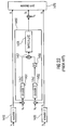
- Fig. 21 shows a similar scenario using analog transmission from the relay station 1450 as explained with the assistance of Fig. 16 .
- the combined LLR L ( u R ) is illustrated. It can be seen from the view chart at the bottom of Fig. 21 that the combined LLR is approximately Gaussian distributed. Since analog transmission is used, large transmit powers need to be utilized, in order to transmit the combined LLR reliably, considering that they are superimposed by AWGN as well.
- Fig. 22 illustrates an option for at least partly overcoming the problem of having to utilize large transmission powers.
- the combined LLRs are processed by signal processor 1458, in which the hyperbolic tangent of the combined LLR is determined and used for analog transmission, also referred to as soft bit transmission in the following.
- a similar option is illustrated in Fig. 23 in which a quantizer 1459 is used for quantizing the LLRs at the relay station 1450, 1903 respectively.
- Fig. 23 shows at the top on the right-hand side the scenario as it was discussed above, involving the two sources 1901 and 1902, the relay station 1903, and the destination 1904. For the simulation results depicted on the left-hand side of Fig.
- the probability density of the LLR L R is shown assuming two quantizer regions separated by the dotted line.
- the two squares represent the quantizer values to be transmitted to the destination 1904. Having only two quantizer regions corresponds to transmitting only one bit per quantized value from the relay station 1903 to the destination 1904.
- almost no degradation due to the quantization occurs with respect to the trans- or mutual information, i.e. almost no information is lost due to quatization.
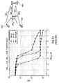
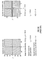
- Fig. 24 shows simulation results on the BER vs. the SNR sd on the link between the sources 1901 or 1902 and the destination 1904. For the simulations, it was assumed that the SNR sr between the sources 1901 and 1902 and the relay station 1903, is 3dB, for the SNR rd between the relay station 1903 and the destination 1904 0dB was assumed.
- the view chart on the left-hand side of Fig. 24 shows BER simulation results for analog transmission indicated by the square markers, soft bit analog transmission indicated by the triangular markers, and quantizer transmission using two quantizer regions, i.e. only one bit per quantizer value by the circular markers.
- the view chart on the left-hand side of Fig. 25 shows the probability density of the LLRs at the input of the quantizer 1459, the quantizer regions are separated by the dotted lines, and the representative values are indicated by square markers.
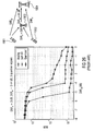
- the view graph on the left-hand side of Fig. 26 shows simulation results for analog transmission indicated by square markers, for soft bit transmission indicated by triangular markers and quantized transmission by circular markers. The simulation results indicate that no degradation at all can be observed when quantization is used.
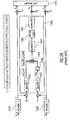
- Fig. 27 illustrates another soft relay and network coding concept wherein quantized transmission from the relay station 1450 to the destination 1470 is used.
- An equation is illustrated at the top of Fig. 27 , which details the combination of the LLRs by the combiner 1457.
- the output of the combiner 1457 corresponds to the LLR, which can be obtained by an XOR combination of the information words u 1 and u 2 , and which is indicated in the equation at the top of Fig. 27 by an arrow operator pointing to the left.
- Fig. 27 illustrates another soft relay and network coding concept wherein quantized transmission from the relay station 1450 to the destination 1470 is used.
- An equation is illustrated at the top of Fig. 27 , which details the combination of the LLRs by the combiner 1457.
- the output of the combiner 1457 corresponds to the LLR, which can be obtained by an XOR combination of the information words u 1 and u 2 , and which is indicated in the equation at the top of Fig. 27 by
- FIG. 27 illustrates, within the relay station 1450, the quantizer 1459 for quantizing the combined LLRs to Z , the source coder 1460 for source coding the quantized combined LLRs and an encoder 1461 for channel encoding the source coded combined LLRs before transmission to the destination 1470.
- Fig. 28 illustrates a similar scenario, but shows that if one of the links between the encoders 1410;1420 and the relay station 1450 degrades, which is exemplified as the link between encoder 1410 and the relay station 1450 in Fig. 28 , the combined LLR becomes zero. Therefore, the SNR on the first hop, on the link between the sources and the relay station can be taken into account in the design of the quantizer.
- Fig. 29 shows another relay station 1450 in which the LLRs are jointly quantized by quantizer 1459 in order to take the signal quality into account, for which Fig. 30 illustrates the details of the quantizer.
- a quantizer for symmetric links is shown for which the mutual information after decoding equals 1.98bits.
- the relevant mutual information or trans-information after quantization equals 1.93bits, and since only two quantizer regions are utilized, only 1-bit is required for encoding the source encoded bits on the link between the relay station 1450 and the base station, or destination 1470.
- the quantizer regions are illustrated in the diagram at the top of Fig. 30 on the left hand side.
- a quantizer for asymmetric links is shown, for which the mutual information after decoding equals 1.16bits.
- the relevant mutual information after quantization equals 1.08bits, and since five quantizer regions are utilized, an average of 2.1bits per source coded bit is required.
- relaying is a promising method in order to overcome coverage limitations at reasonable cost.
- straightforward relaying methods lead to a capacity penalty factor of 0.5, since a time slot has to be split into two hops.
- Another problem is the processing delay in the relay, which may lead to a non-tolerable increase in the round-trip delay, which dues to the decoding at the relay station according to the above described concepts.
- the alternative of an amplify-and-forward relaying method which circumvents the decoding delay at the relay station, causes a lower processing delay, however, these schemes suffer from noise amplification in the relay.
- the object is achieved by a relay station according to claim 1, a method for relaying according to claim 6, a decoder according to claim 17, a method for decoding according to claim 11, and a system according to claim 13.
- Embodiments of the present invention are based on the finding that performance improvements can be achieved with respect to delay as well as with respect to error propagation, if the quantization rule at a relay station can be adapted to the signal quality of the received signals at the relay station, e.g. based on whether the signals at the relay station have been received correctly or not.
- the relay can use a quantizer from a set of available quantizers to compress its soft information, depending on the particular realizations of the channel fading on its incoming links, as for example, generally on an error detection mechanism for each incoming link to efficiently use the resources of the relay-destination link.
- the relay station After soft decoding of a received signal, the relay station has soft information available about its received signal. This soft information can be quantized by an optimized quantizer and forwarded to the destination, where the quantization can be based on a quantization rule, which in turn, is based on an error or signal quality detection mechanism.
- Embodiments of the present invention are further based on the finding that optionally, signals of multiple users can be quantized jointly, or a combination of them can be quantized at the relay station.
- the destination i.e. at the decoder
- joint decoding for all users, which have been processed jointly at the relay station can be performed using an iterative algorithm.
- Embodiments can achieve the advantage that noise enhancement is prevented at the relay station, since explicitly computed soft information is forwarded by the relay, rather than an amplified version of the noisy received signal.
- embodiments may achieve improved transmission characteristics as the relay station may use one quantizer from a set of available quantizers to compress its soft information, depending on the error detection or quality determination scheme at the relay station, and in further embodiments, even on the particular signal qualities of the signals received. Embodiments may therefore enable an efficient use of the resources between the relay station and the destination by taking knowledge about the quality of the received signals into account.
- Embodiments may achieve higher user satisfaction through higher throughputs and lower delays. Embodiments may provide coverage extensions with low cost relay stations and improved performance compared to conventional amplify-and-forward or decode-and-forward relay stations. Embodiments of systems carrying out said relaying concepts may provide diversity gain by using said relay stations and may realize low delay and high throughput, since the signals of multiple users can be processed, i.e. quantized, in combination or jointly with high efficiency at a relay station.
- Embodiments may comprise a decoder, which can for example, be implemented at a destination, a base station, a NodeB, etc., for decoding the quantized information from a relay station, and therewith realizing the above-described benefits.
- a decoder which can for example, be implemented at a destination, a base station, a NodeB, etc., for decoding the quantized information from a relay station, and therewith realizing the above-described benefits.
- each channel realization of a radio channel can be viewed as an additive white Gaussian noise (AWGN) channel with some instantaneous signal-to-noise ratio (SNR).
- AWGN additive white Gaussian noise
- SNR signal-to-noise ratio
- the relay station can then select a suitable quantizer for the particular realization of the fading coefficients on the source-relay links based on error or signal quality detection and/or the values of SNR sr,1 and SNR sr,2 .
- Each of the quantizers available at the relay may be designed with the information bottleneck method for the general (asymmetric) setting described in G. Zeitler, R. Koetter, G. Bauch, and J.Widmer, "On quantizer design for soft values in the multiple-access relay channel," submitted to the 2009 International Conference on Communications . Details of the quantizer design will be provided subsequently.
- the performance of the relaying scheme using quantized transmission in a block fading environment can be evaluated.
- the channel code specified in the UMTS will be used as described by European Telecommunications Standards Institute, "Universal mobile telecommunications system (UMTS): Multiplexing and channel coding (FDD),” 3GPP TS 125.212 version 3.4.0, Tech. Rep., 2000 , standard for protection of the individual links in the network.
- UMTS Universal mobile telecommunications system
- FDD Multiplexing and channel coding
- Fig. 1a shows a general system model in which a first channel encoder 10a encodes an information word u 1 to a transmission symbol x 1 , which is transmitted to a first channel 12a to a relay station 100. Moreover, the same transmission symbol x 1 is transmitted through a second radio channel 14a to the destination 300. The received signal at the destination 300 is termed y d,1 . Furthermore, Fig. 1a shows a second channel encoder 10b encoding an information word u 2 to a second transmission symbol x 2 which is transmitted through a second radio channel 12b to the relay station 100.
- the signals received at the relay station are termed y r,1 for the signal received from the first channel encoder 10a and y r,2 for the signal received from the second channel encoder.
- the destination 300 receives a signal y d,2 from the second channel encoder 10b through the channel 14b.
- the relay station 100 transmits a signal x r through channel 14c through which the received signal y r is received by the destination 300.
- the distances between the sources and the relay, between the sources and the destination, and between the relay and the destination are given by d sr,i , d sd , i , and d rd , and the path-loss exponent is given by p.
- the fading coefficients a sr,i , a sd,i , and a rd are mutually independent and Rayleigh distributed with E [
- 2 ] E [
- 2 ] E [
- 2 ] 1.
- 2 ⁇ sr,i , ⁇ sd,i
- 2 ⁇ sd , i and ⁇ rd
- Fig. 1b shows an embodiment of a relay station 100 for being operative in a mobile communication system.
- GSM Global System for Mobile Communication
- UMTS Universal Mobile Telecommunication System
- LTE Long Term Evolution
- LTE-A Long Term Evolution Advanced
- WLAN Wireless Local Area Network
- the relay station 100 depicted in Fig. 1b comprises a receiver 110 for receiving a radio signal from a source, the radio signal comprising symbols representing encoded information, the encoded information being based on an encoding rule and comprising payload information and redundancy information.
- a symbol or transmit word may correspond to x 1 or x 2 .
- the relay station 100 further comprises a decoder 120 for determining soft information on the payload information and the redundancy information based on a symbol and a decoding rule associated with the encoding rule, the soft information comprising an information on a symbol and reliability information on the information on the symbol.
- the relay station 100 comprises a signal quality detector 130 for detecting a signal quality measure based on the soft information to obtain a signal quality indication.
- the relay station 100 further comprises a quantization rule selector 140 for selecting a quantization rule from a plurality of quantization rules based on the signal quality indication and a quantizer 150 for quantizing the soft information of the payload information based on the selected quantization rule to obtain quantized soft information. Furthermore, the relay station 100 comprises a transmitter 160 for transmitting the quantized soft information to a destination.
- the relay station 100 may comprise a signal quality detector 130 which is further adapted for determining an error based on the soft information on the redundancy information to obtain an error indication and the quantization rule selector 140 can be adapted for selecting a quantization rule further based on the error indication.
- CRC Cyclic Redundancy Check
- the relay station 100 may have a receiver 110 for receiving a radio signal y r,1 through the radio channel 12a from the source or channel encoder 10a.
- the quantization rule selector 140 can then be adapted for taking into account the signal quality measure when selecting the quantization rule.
- Embodiments of the quantization rule selector 140 may base the selection of the quantization rule on one of or a combination of the group of an outcome of a CRC, a BER, an FER, a SNR, a SINR, a SIR, a transmission capacity, etc.
- the receiver 110 can be adapted for receiving another radio signal from another source, the other radio signal comprising other symbols representing other encoded information, the other encoded information being based on another encoding rule and comprising other payload information and other redundancy information.
- the relay station 100 may comprise a receiver 110 which is adapted for receiving another radio signal y r,2 from the encoder 10b, i.e. comprising another symbol.
- the decoder 120 can be adapted for determining other soft information on the other payload information and the other redundancy information based on another symbol and another decoding rule the other decoding rule being associated with the other encoding rule, the other soft information comprising information on the other symbol, and reliability information on the information on the other symbol.
- the signal quality detector 130 can be adapted for determining another signal quality measure based on the other soft information to obtain another signal quality indication and correspondingly the quantization rule selector 140 can be adapted for selecting the quantization rule further based on the other signal quality indication.
- the quantizer 150 can be adapted for quantizing a combination of the soft information on the payload information and the other soft information on the other payload information to obtain the quantized soft information and/or for jointly quantizing the soft information on the payload information and the other soft information on the other payload information to obtain the quantized soft information.
- the signal quality detector 130 can be further adapted for determining another error based on the other soft information on the other redundancy information to obtain another error indication and the quantization rule selector 140 can be adapted for selecting the quantization rule further based on the other error indication.
- channel coding at the sources i.e. at the source and the other source
- channel codes at the sources are rate 1/2 turbo codes, as specified in the UMTS Standard with information block length k 1 and k 2 , respectively.
- the relay station performs soft decoding using its received words y r,1 and y r,2 .
- the output of a turbo decoder does not consist of true LLRs but rather of the beliefs of the belief propagation decoder
- the outputs of the soft decoders at the relay are still referred to as L 1 and L 2 .
- the turbo decoder can be seen as a device generating beliefs about the corresponding codeword, and since some situations are focused on where the relay cannot decode error-free, it is of particular interest whether the beliefs produced by the turbo decoder carry sufficient amount of mutual or trans-information about the code bits if reliable decoding is not possible. It was shown in P. E.
- Another effect observed is connected with the behavior of the mutual information between the decoder output and the codeword versus the number of iterations: in some cases, mutual information decreases again if the number of iterations is increased above a certain value. That effect, however, is fairly small, and therefore, although some of the stopping criteria found in the literature can be shown to halt the iterative process close to the maximal value of mutual information, a fairly small number of iterations at the relay are simply performed.
- Fig. 2 shows an embodiment of a decoder 300 for decoding a first encoded codeword to obtain a first soft information on a first codeword and for decoding a second encoded codeword to obtain second soft information on the second codeword.
- the decoder 300 comprises a first soft decoder 310 for determining the first soft information on the first codeword based on the first encoded codeword, and a second soft decoder 320 for determining second soft information on the second codeword based on the second encoded codeword and on second a-priori information.
- the decoder 300 comprises a first soft information renderer 330 for providing the second a-priori information based on the first soft information and quantized soft information, the quantized soft information being based on a combination of the first codeword and the second codeword. Furthermore, the decoder 300 comprises a second soft information renderer 340 for providing first a-priori information based on the second a-priori information, the quantized soft information and the second soft information.
- the first soft decoder 310 is adapted for determining updated first soft information on the first codeword based on the first encoded codeword and the first a-priori information.
- the first soft information renderer 330 can be adapted for providing updated second a-priori information based on the updated first soft information, the first a-priori information and the quantized soft information.
- the first soft decoder 310 can be adapted for determining the first soft information in terms of an LLR
- the second soft decoder 320 can be adapted for determining the second soft information in terms of an LLR
- the first soft information renderer 330 can be adapted for providing the second a-priori information in terms of an LLR
- the second soft information renderer 340 can be adapted for providing the first a-priori information in terms of an LLR.
- the decoder 300 may further comprise a receiver for receiving encoded quantized soft information and a decoder for decoding the encoded quantized soft information and a requantizer for providing the quantized soft information based on a quantization rule and the decoded encoded quantized soft information, wherein the receiver can be adapted for also receiving an information on the quantization rule.
- the receiver can be adapted for being operative in a mobile communication system, for example, a cellular system similar to the above-mentioned mobile communication systems.
- Fig. 3 illustrates a more detailed embodiment of an iterative decoder 300.
- Fig. 3 shows the first soft decoder 310 for determining first soft information at its output on the first codeword based on the first encoded codeword y 1 .
- the first soft decoder 310 is also adapted for determining first soft information or updated first soft information on the first codeword based on the encoded first codeword y 1 , and first a-priori information L A 1 .
- Fig. 3 shows the second soft decoder 320 for determining second soft information at its output on the second codeword based on the second encoded codeword y 2 and on second a-priori information L A 2 .
- Fig. 3 shows a first soft information renderer 330 for providing the second a-priori information L A 2 based on the first soft information provided by the first soft decoder 310 and quantized soft information y r received from a relay station 100.
- the first soft information renderer 330 first determines first extrinsic information L E 1 , for example, as a difference between the first soft information provided at the output of the first soft decoder 310 and the first a-priori information L A 1 .
- all soft information is considered in terms of LLRs.
- Fig. 3 shows a first soft information renderer 330 for providing the second a-priori information L A 2 based on the first soft information provided by the first soft decoder 310 and quantized soft information y r received from a relay station 100.
- the first soft information renderer 330 first determines first extrinsic information L E 1 , for example, as a difference between the first soft information provided at the output of the first soft decoder 310 and the
- the first soft information renderer 330 has a relay check node 335 in which interleaved second a-priori information is determined, based on a combination of the extrinsic information L E 1 and the quantized soft information. Moreover, the first soft information renderer 330 operates a de-interleaver 338 which de-interleaves L ⁇ ⁇ A 2 to obtain the second a-priori information L A 2 .
- Fig. 3 shows the second soft information renderer 340 providing first a-priori information L A 1 .
- the second soft information renderer 340 first determines second extrinsic information L E 2 based on a difference between the second soft information and the second a-priori information.
- the second soft information renderer 340 utilizes an interleaver 348 to interleave the second extrinsic information, and utilizes the relay check node 345 in order to combine the interleaved second extrinsic information L ⁇ ⁇ E 2 and the quantized soft information y r to obtain the first a-priori information L A 1 .
- each soft decoder is a turbo decoder. Iterative decoding in this case consists of inner iterations of the turbo decoder, and outer iterations over the relay check nodes. Like at the relay, it was found that performing a rather small number (4-6) of inner iterations gave good results in terms of extrinsic information.
- each of the soft decoders 310;320 may be implemented as a turbo decoder.
- the iterative decoder consists of four components in total, the EXIT curves for the two decoders 310;320 and the two relay check nodes 332;342 are the same due to the symmetry in the setup. Therefore, to obtain the EXIT chart for the entire decoder, it suffices to plot two curves only, one for the component decoder 310;320 and one for the relay check node 332;342.
- the goal is then to find a way of forwarding that information to the destination such that the EXIT curve in the decoder has maximal slope, subject to a constraint on the rate on the relay-destination link.
- the distortion measure has to be chosen and fixed in advance, and finding the right distortion measure for a particular problem is not an easy task in general.
- the function of the relay node should be: given an LLR L, transmit a quantized version Z that contains as much relevant information, which is information about X . That is, instead of forcing, e. g., the squared error between L and Z to be below some threshold, the goal is to preserve as much information as possible in Z about X .
- Tishby et al. take the following approach towards quantization of a random variable L .
- the goal is to min p z
- I ( X ; Z ) ⁇ I ( X ; L ) due to the data processing inequality. That is, all that one can possibly aim for is preserving all the information available at the relay node about X in the quantizer output Z . Therefore, D ⁇ has to satisfy 0 ⁇ D ⁇ ⁇ I ( X ; L ).
- IBM Information Bottleneck Method
- the IBM can be used to compute a quantizer or quantization rule which, for a given source-relay SNR, maximizes the relevant information I ( X ; Z ), subject to a constraint on the rate on the relay destination link.
- the parameter ⁇ in the optimization algorithm has to be greatly larger than one to yield a deterministic mapping p ( z
- the rate of the quantizer chosen at the relay is such that the quantizer output Z can be communicated reliably to the destination.
- the quantizer design on L r will be referred to as the XOR-solution to the compression problem at the relay.
- the quantizer should be adapted to operate on L 1 and L 2 ⁇ directly, and accordingly, the quantizer design algorithm as well.
- the relay check node in the receiver processes Z and L E i to produce a-priori information for the corresponding component decoder.
- L E j I X i ; Z
- L E j . Due to the characteristic property of the relay check node of being almost a straight line, the problem simplifies to maximizing the output information for perfect input information I in 1.
- I rel I ( X 1 ; Z
- I rel I ( X 1 ; Z
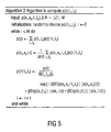
- Fig. 5 provides a pseudo-code of algorithm 2, which may be carried out at the quantizer 150.
- the quantizer design in an embodiment may follow the above-described framwork using the general formulation of the information bottleneck method. Now, however, the distribution p ( z
- the point-to-point link not using the relay is taken as a reference for this system.
- the relay station is to be placed much closer to the destination than to the sources.
- the symmetry assumed here is only with respect to the distances and hence in terms of average SNR, but not in terms of instantaneous SNR.
- Fig. 6 illustrates two scenarios which are considered for the following simulations and which establish different fading cases.
- Fig. 6 illustrates the first case on the left-hand side in which two sources 61 and 62 transmit signals to the base station 63 and the destination 64, where in the first case the relay station 63 is located closer to the sources 61 and 62 than the destination 64.
- case 2 is depicted which differs from case 1 in that the relay station 63 is farther away from the sources 61 and 62 than the destination 64.
- the relay is placed behind the base station, resulting in an even worse source-relay link.
- d sr (3/2)
- This set of quantizers can be computed offline for various values of ⁇ sr ,1 and ⁇ sr ,2 . Assuming an error detection mechanism at the relay, the quantizers can be classified into three categories. First both users are decoded incorrectly at the relay, second only one user is decoded incorrectly at the relay, and third both users are decoded error-free.
- the relay station 100 may comprise a transmitter 160 which is adapted for transmitting an information on the selected quantization rule to the destination.
- the destination determines the quantizer used by the relay station 100 which in such embodiments is carried out by signaling the choice of the quantization rule or the quantizer to the destination or decoder 300, for example, by using 9 bits.
- the signaling is perfect, i.e. the decoder 300 or destination is completely informed about the quantizer or quantization rule selected by the relay station 100.
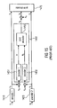
- Fig. 7 illustrates another embodiment for the general case.
- Fig. 7 shows an embodiment of the relay station 100, in which, for the sake of simplicity, the receiver 110 is not shown.
- Fig. 7 shows a decoder 120 for determining the soft information L 1 and L 2 based on the received symbols or words y r , 1 and y r ,2 .
- the decoder 120 shown in Fig. 7 is implemented as two separate soft decoders 121 and 122, which is one configuration among multiple configurations in embodiments of the decoder 120.
- Fig. 7 shows an interleaver 701 and a quantizer core 702.
- the section 700 comprises the signal quality detector 130, the quantization rule selector 140, and the quantizer 150, of which the details are not shown in Fig. 7 .
- the quantized soft information Z is available, which is then provided to a source encoder 710.
- the source encoder 710 is comprised in the transmitter 160.
- the transmitter 160 may further comprise a source coder 710 for source coding the quantized soft information Z .
- the transmitter 160 may comprise a channel encoder 720, for channel coding the source coder quantized soft information before transmitting according to Fig. 7 .
- the channel coder 720 may be adapted to operating at adaptive coding rates.
- the channel coder 720 can be configured to adapt the coding rate to a transmission capacity of a radio link to the destination.
- the source coding is necessary at this point since the quantizer output symbols are not equally likely in general.
- the source encoder output bits are channel encoded using the UMTS turbo code of appropriate rate and before being modulated using 16-QAM yielding the relay codeword x r of length 4000. Note that the rate of the turbo code at the relay must be adaptive since the rate of the quantizer depends on the values of the instantaneous SNR.
- Fig. 8a illustrates an embodiment of a relay check node 335 or 345 as explained in the above embodiments of the first soft information renderer 330 or the second soft information renderer 340, respectively.
- the relay check node 335 or 345 depicted in Fig. 8a provides the first a-priori information L A 1 , or an interleaved version of the second a-priori information L ⁇ ⁇ A 2 based on the first extrinsic information L E 1 or an interleaved version of the second extrinsic information L ⁇ ⁇ E 2 and the received quantized soft information y r .
- a channel decoder 805 may be comprised in the relay check node 335 or 345, in order to channel decode the encoded quantized soft information y r to obtain decoded quantized soft information û r . As indicated in Fig.
- a CRC check may also be carried out.
- a source decoded version of the quantized soft information ⁇ may be obtained by the source decoder 810 which can be comprised in embodiments of the relay check node 335 or 345, respectively.
- An LLR processor 815 may then be utilized to process the estimate of the quantized soft information ⁇ and the extrinsic information to obtain the a-priori information.
- an error detection mechanism e.g. CRC
- generally signal quality detection SNR, SINR, BER, FER, etc.
- the error and/or signal quality detection is used to select the appropriate quantizer, and the destination uses the error or signal quality detection mechanism to decide whether to make use of the signal received from the relay, since, if errors are detected in û r (cf. Fig. 8a ), the entire received signal block of the relay is discarded to avoid error propagation through the source decoder.
- Fig. 8b illustrates another embodiment of a relay station 100, embedded in a scenario as it has been discussed with respect to Fig. 1a .
- Fig. 8b depicts the details of the relay station 100 in which the error detector 130 is implemented as two separate error detectors 131 and 132 carrying out CRC checks on the first and second soft information output by the two decoders 121 and 122.
- the quantizer core 702 is assumed to comprise the quantization rule selector 140 and the quantizer 150.
- the two encoders 10a and 10b utilize turbo codes.
- the embodiment of the relay station 100 of Fig. 8b shall illustrate that the quantizer, i.e. the quantization rule may depend on the SNRs on the source relay links, i.e. on the signal quality between encoders 10a and 10b, and the relay station, as well as on the SNR between the relay station and the destination 300.
- the error detector 130 and the CRC checks 131 and 132 illustrate that embodiments may select the quantization rules dependent on whether the transmission between a source 10a, 10b, and the relay station 100 was error free, or erroneous.
- Fig. 8c shall illustrate the difference between the two cases of error free or erroneous decoding of the source to relay station signals in more detail.
- Fig. 8c illustrates the embodiment as depicted in Fig. 8b at the top, as well as two distributions of the soft information in terms of LLRs at the output of a decoder, on the left-hand side the error free decoding case is depicted, while on the right-hand side the case with the decoding errors is depicted.
- UMTS turbo codes at a rate of 1/2 at an SNR of -2dB was assumed.
- the probability, that values around 0 occur is vanishing, which indicates the error free decoding case.
- On the right-hand side it can be seen that there is a probability that soft information of 0 value will occur, for which error free decoding is not possible.
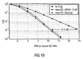
- Fig. 9 illustrates simulation results of the BER vs. the average source to destination SNR in dB for case 1, in which point-to-point transmission, a relay station to destination AWGN channel of 10dB, and a relay station-to-destination Rayleigh fading channel have been considered.
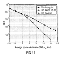
- Fig. 11 illustrates BERs vs. average source to destination SNR in dB for the second case, in which the same channel types have been considered, and consequently, Fig. 12a illustrates the corresponding frame error rates for the second case.
- case 1 where the relay is placed between the sources and the destination.
- the BER is plotted and frame-error-rate (FER) of the reference point-to-point link and the system using the relay with the three types of relay-destination links in Figs. 9 and 10 .
- FER frame-error-rate
- the best performance is achieved if the relay-destination link does not experience fading, and it can be seen that in this case, diversity is achieved.
- the relay-destination link is Rayleigh block fading, although at a slightly inferior performance than in a case where the relay-destination link is AWGN.
- Embodiments may realize an adaptive relay station that quantizes the soft information obtained after decoding. Embodiments may therewith avoid noise amplification as being introduced by amplify-and-forward methods and embodiments may further avoid error propagation as introduced by decode-and-forward schemes. Embodiments may provide the advantages of increased reliability in fading environments and adaptive processing at the relay station, which is made dependent on realizations of the fading channels on the source relay links, the signal quality measures, respectively.
- Embodiments may achieve advantages by introducing moderate signaling requirements for the quantizer choice between the relay station and the destination.
- FEC Forward Error Correction
- LDPC Low Density Parity Check Codes
- Embodiments may overcome the problem of error propagation by forwarding soft information after decoding to the destination as it occurs for high performance codes in the form of turbo codes or LDPC codes.
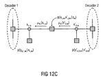
- Fig. 12b illustrates one section of the decoding graph, wherein on the left-hand side decoder 1 refers to the first soft decoder 310, and the decoder 2 on the right-hand side refers to the second soft decoder 320.
- the nodes labeled x 1, m and x 2, m are two variable nodes of the two different component channel codes coupled by the quantization at the relay.
- the direct observations from the two sources are the function nodes p ( y d ,1, m
- the destination exploits its knowledge of the quantizer chosen by the relay to obtain p ( x 1 , x 2
- z ) is the message passing equivalent of the LLR block 815 in Fig. 8a .
- the message passing rules are applied for function nodes to p ( x 1 , x 2
- Equation (5) is closely related to the boxplus computation in the symmetric case. Note that if L x 1 , m , x ⁇ 2 , m
- z m and - L ⁇ x 1 , m , x ⁇ 2 , m - 1
- m L A , m 1 L ⁇ E , m 2
- z m + e - L ⁇ x 1 , m - 1 , x ⁇ 2 , m
- Embodiments of the present invention may utilize the quantizer design framework which was introduced above for the received LLRs at the relay in symmetric AWGN channels using, for example, the IBM. Furthermore, embodiments may extend this method to the general case, i.e. lifting the symmetry requirement on the source-relay channels. Embodiments may, therefore, provide the advantage that efficient processing may be carried out at the relay station for several users jointly. Moreover, low delay may be achieved since no decoding has to be performed at the relay and noise amplification can be avoided.
- the inventive methods may be implemented in hardware or in software.
- the implementation can be formed using a digital storage medium, in particular a disc, a DVD or a CD, having an electronically readable control signal stored thereon which cooperates with the programmable computer, such that the inventive methods are performed.
- the present invention is therefore a computer program product with a program code for a machine-readable carrier, the program code being operative for performing the inventive methods when the computer program runs on a computer.
- the inventive methods are therefore a computer program having a program code for performing at least one of the inventive methods when the computer program runs on a computer.
Landscapes
- Engineering & Computer Science (AREA)
- Computer Networks & Wireless Communication (AREA)
- Signal Processing (AREA)
- Power Engineering (AREA)
- Mobile Radio Communication Systems (AREA)
- Detection And Prevention Of Errors In Transmission (AREA)
- Radio Relay Systems (AREA)
Claims (13)
- Eine Weiterleitungsstation (100), um bei einem Mobilkommunikationssystem wirksam zu sein, die folgende Merkmale aufweist:einen Empfänger (110) zum Empfangen eines Funksignals von einer Quelle, wobei das Funksignal Symbole aufweist, die codierte Informationen darstellen, wobei die codierten Informationen auf einer Codierungsregel beruhen und Nutzlastinformationen und Redundanzinformationen aufweisen, wobei der Empfänger (110) zum Empfangen eines anderen Funksignals von einer anderen Quelle angepasst ist, wobei das andere Funksignal andere Symbole aufweist, die andere codierte Informationen darstellen, wobei die anderen codierten Informationen auf einer anderen Codierungsregel beruhen und andere Nutzlastinformationen und andere Redundanzinformationen aufweisen;einen Decodierer (120) zum Bestimmen weicher Informationen über die Nutzlastinformationen und die Redundanzinformationen auf der Basis eines Symbols und einer der Codierungsregel zugeordneten Decodierungsregel, wobei die weichen Informationen Informationen über das Symbol und Zuverlässigkeitsinformationen über die Informationen über das Symbol aufweisen, wobei der Decodierer (120) zum Bestimmen anderer weicher Informationen über die anderen Nutzlastinformationen und die anderen Redundanzinformationen auf der Basis eines anderen Symbols und einer anderen Decodierungsregel, die der anderen Codierungsregel zugeordnet ist, angepasst ist, wobei die anderen weichen Informationen Informationen über das andere Symbol und Zuverlässigkeitsinformationen über die Informationen über das andere Symbol aufweisen;dadurch gekennzeichnet, dass sie ferner folgende Merkmale aufweist:einen Signalqualitätsdetektor (130) zum Erfassen eines Signalqualitätsmaßes auf der Basis der weichen Informationen, um eine Signalqualitätsangabe zu erhalten, wobei der Signalqualitätsdetektor (130) zum Erfassen eines anderen Signalqualitätsmaßes auf der Basis der anderen weichen Informationen, um eine andere Signalqualitätsangabe zu erhalten, angepasst ist;einen Quantisierungsregelselektor (140) zum Auswählen einer Quantisierungsregel aus einer Mehrzahl von Quantisierungsregeln auf der Basis der Signalqualitätsangabe und auf der Basis der anderen Signalqualitätsangabe;einen Quantisierer (150) zum Quantisieren einer Kombination der weichen Informationen über die Nutzlastinformationen und der anderen weichen Informationen über die anderen Nutzlastinformationen, um quantisierte weiche Informationen zu erhalten, oder zum gemeinsamen Quantisieren der weichen Informationen über die Nutzlastinformationen und der anderen weichen Informationen über die anderen Nutzlastinformationen auf der Basis der ausgewählten Quantisierungsregel, um die quantisierten weichen Informationen zu erhalten; undeinen Sender (160) zum Senden der quantisierten weichen Informationen an einen Zielort, wobei der Sender (160) zum Senden von Informationen über die ausgewählte Quantisierungsregel angepasst ist.
- Die Weiterleitungsstation (100) gemäß Anspruch 1, bei der der Signalqualitätsdetektor (130) ferner zum Bestimmen eines Fehlers auf der Basis der weichen Informationen über die Redundanzinformationen, um eine Fehlerangabe zu erhalten, angepasst ist, und bei der der Quantisierungsregelselektor (140) zum Auswählen der Quantisierungsregel ferner auf der Basis der Fehlerangabe angepasst ist, wobei der Signalqualitätsdetektor (130) ferner zum Bestimmen eines anderen Fehlers auf der Basis der anderen weichen Informationen über die anderen Redundanzinformationen, um eine andere Fehlerangabe zu erhalten, angepasst ist, und wobei der Quantisierungsregelselektor (140) zum Auswählen der Quantisierungsregel ferner auf der Basis der anderen Fehlerangabe angepasst ist.
- Die Weiterleitungsstation (100) gemäß einem der Ansprüche 1 bis 2, bei der der Sender (160) ferner einen Quellencodierer zum Quellencodieren der quantisierten weichen Informationen und einen Kanalcodierer zum Kanalcodieren der quellencodierten quantisierten weichen Informationen vor dem Senden aufweist.
- Die Weiterleitungsstation (100) gemäß Anspruch 3, bei der der Kanalcodierer bei einer adaptiven Codierungsrate arbeitet, wobei der Kanalcodierer dazu konfiguriert ist, die Codierungsrate an eine Sendekapazität einer Funkverbindung zu dem Zielort anzupassen.
- Die Weiterleitungsstation (100) gemäß einem der Ansprüche 2 bis 4, bei der der Signalqualitätsdetektor (130) zum Erfassen der Fehlerangabe oder der anderen Fehlerangabe auf der Basis einer zyklischen Redundanzprüfung angepasst ist.
- Ein Verfahren zum Weiterleiten bei einem Mobilkommunikationssystem, das folgende Schritte aufweist:Empfangen eines Funksignals von einer Quelle, wobei das Funksignal Symbole aufweist, die codierte Informationen darstellen, wobei die codierten Informationen auf einer Codiererregel beruhen und Nutzlastinformationen und Redundanzinformationen aufweisen;Empfangen eines anderen Funksignals von einer anderen Quelle angepasst ist,wobei das andere Funksignal andere Symbole aufweist, die andere codierte Informationen darstellen, wobei die anderen codierten Informationen auf einer anderen Codierungsregel beruhen und andere Nutzlastinformationen und andere Redundanzinformationen aufweisen;Bestimmen weicher Informationen über die Nutzlastinformationen und die Redundanzinformationen auf der Basis eines Symbols und einer der Codierungsregel zugeordneten Decodierungsregel, wobei die weichen Informationen Informationen über das Symbol und Zuverlässigkeitsinformationen über die Informationen über das Symbol aufweisen;Bestimmen anderer weicher Informationen über die anderen Nutzlastinformationen und die anderen Redundanzinformationen auf der Basis eines anderen Symbols und einer anderen Decodierungsregel, die der anderen Codierungsregel zugeordnet ist, wobei die anderen weichen Informationen Informationen über das andere Symbol und Zuverlässigkeitsinformationen über die Informationen über das andere Symbol aufweisen;gekennzeichnet durch:Erfassen eines Signalqualitätsmaßes auf der Basis der weichen Informationen, um eine Signalqualitätsangabe zu erhalten;Erfassen eines anderen Signalqualitätsmaßes auf der Basis der anderen weichen Informationen, um eine andere Signalqualitätsangabe zu erhalten;Auswählen einer Quantisierungsregel aus einer Mehrzahl von Quantisierungsregeln auf der Basis der Signalqualitätsangabe und auf der Basis der anderen Signalqualitätsangabe;Quantisieren einer Kombination der weichen Informationen über die Nutzlastinformationen und der anderen weichen Informationen über die anderen Nutzlastinformationen auf der Basis der ausgewählten Quantisierungsregel, um quantisierte weiche Informationen zu erhalten, oder zum gemeinsamen Quantisieren der weichen Informationen über die Nutzlastinformationen und der anderen weichen Informationen über die anderen Nutzlastinformationen auf der Basis der ausgewählten Quantisierungsregel, um die quantisierten weichen Informationen zu erhalten;Senden der quantisierten weichen Informationen an einen Zielort; undSenden von Informationen über die ausgewählte Quantisierungsregel.
- Ein Decodierer (300) zum Decodieren eines ersten codierten Codewortes, um erste weiche Informationen über ein erstes Codewort x1 zu erhalten, und zum Decodieren eines zweiten codierten Codewortes, um zweite weiche Informationen über ein zweites Codewort x2 zu erhalten, der folgende Merkmale aufweist:einen ersten weichen Decodierer (310) zum Bestimmen der ersten weichen Informationen über das erste Codewort x1 auf der Basis des ersten codierten Codeworts, wobei der erste weiche Decodierer (310) zum Bestimmen der ersten weichen Informationen bezüglich eines LLR (LLR = log-likelihood ratio, logarithmiertes Wahrscheinlichkeitsverhältnis) angepasst ist;einen zweiten weichen Decodierer (320) zum Bestimmen der zweiten weichen Informationen über das zweite Codewort x 2 auf der Basis des zweiten codierten Codeworts und zweiter a-priori-Informationen
 eine erste Weiche-Informationen-Wiedergabevorrichtung (330) zum Bereitstellen der zweiten a-priori-Informationen


 wobei m ein Index innerhalb eines Wortes ist, x'2 eine verschachtelte Version von x2 ist, wobei die quantisierten weichen Informationen z derart sind, dass x 1,m und x'2,m durch die Wahrscheinlichkeitsdichte p(x1,m ,x' 2,m |zm ) zugeordnet werden, wobei


 eine zweite Weiche-Informationen-Wiedergabevorrichtung (340) zum Bereitstellen der ersten a-priori-Informationen

 wobei
wobei


 wobei der erste weiche Decodierer (310) zum Bestimmen aktualisierter erster weicher Informationen über das erste Codewort x 1 auf der Basis des codierten ersten Codeworts und der ersten a-priori-Informationen
- Der Decodierer (300) gemäß Anspruch 7, bei dem die erste Weiche-Informationen-Wiedergabevorrichtung (330) zum Bereitstellen aktualisierter zweiter a-priori-Informationen auf der Basis der aktualisierten ersten weichen Informationen, der ersten a-priori-Informationen

- Der Decodierer (300) gemäß einem der Ansprüche 7 oder 8, der ferner einen Empfänger zum Empfangen codierter quantisierter weicher Informationen und einen Decodierer zum Decodieren der codierten quantisierten weichen Informationen und einen Neuquantisierer zum Bereitstellen der quantisierten weichen Informationen auf der Basis einer Quantisierungsregel und der decodierten codierten quantisierten weichen Informationen aufweist, wobei der Empfänger ferner zum Empfangen von Informationen über die Quantisierungsregel angepasst ist.
- Der Decodierer (300) gemäß einem der Ansprüche 7 bis 9, bei dem der Empfänger zum Empfangen in einem zellularen Mobilkommunikationssystem angepasst ist.
- Ein Verfahren zum Decodieren eines ersten codierten Codeworts, um erste weiche Informationen über ein erstes Codewort x 1 zu erhalten, und zum Decodieren eines zweiten codierten Codeworts, um zweite weiche Informationen über ein zweites Codewort x 2 zu erhalten, wobei das Verfahren folgende Schritte aufweist:Bestimmen der ersten weichen Informationen über das erste Codewort x 1 auf der Basis des ersten codierten Codeworts bezüglich eines LLR;Bestimmen zweiter weicher Informationen über das zweite Codewort x 2 auf der Basis des zweiten codierten Codeworts und zweiter a-priori-Informationen
 Bereitstellen der zweiten a-priori-Informationen

 wobei m ein Index innerhalb eines Wortes ist, x'2 eine verschachtelte Version von x2 ist, wobei die quantisierten weichen Informationen z derart sind, dass x 1,m und x'2,m durch die Wahrscheinlichkeitsdichte p(x 1,m ,x' 2,m |zm ) zugeordnet werden, wobei


 Bereitstellen erster a-priori-Informationen

 wobei
wobei


undBestimmen aktualisierter erster weicher Informationen über das erste Codewort x 1 auf der Basis des codierten ersten Codeworts und der ersten a-priori-Informationen
- Computerprogramm, das einen Programmcode zum Ausführen eines der Verfahren gemäß Anspruch 6 oder 11, wenn das Programm auf einem Computer oder Prozessor abläuft, aufweist.
- System, das eine Weiterleitungsstation (100) gemäß einem der Ansprüche 1 bis 5 und einen Decodierer (300) gemäß einem der Ansprüche 7 bis 10 aufweist.
Priority Applications (2)
| Application Number | Priority Date | Filing Date | Title |
|---|---|---|---|
| EP20080022422 EP2202904B1 (de) | 2008-12-23 | 2008-12-23 | Relaisstation und Dekodierer |
| JP2009292357A JP4918586B2 (ja) | 2008-12-23 | 2009-12-24 | 中継局及び復号器 |
Applications Claiming Priority (1)
| Application Number | Priority Date | Filing Date | Title |
|---|---|---|---|
| EP20080022422 EP2202904B1 (de) | 2008-12-23 | 2008-12-23 | Relaisstation und Dekodierer |
Publications (2)
| Publication Number | Publication Date |
|---|---|
| EP2202904A1 EP2202904A1 (de) | 2010-06-30 |
| EP2202904B1 true EP2202904B1 (de) | 2013-10-02 |
Family
ID=40827047
Family Applications (1)
| Application Number | Title | Priority Date | Filing Date |
|---|---|---|---|
| EP20080022422 Active EP2202904B1 (de) | 2008-12-23 | 2008-12-23 | Relaisstation und Dekodierer |
Country Status (2)
| Country | Link |
|---|---|
| EP (1) | EP2202904B1 (de) |
| JP (1) | JP4918586B2 (de) |
Cited By (1)
| Publication number | Priority date | Publication date | Assignee | Title |
|---|---|---|---|---|
| WO2016054070A1 (en) * | 2014-09-29 | 2016-04-07 | Huawei Technologies Co., Ltd. | System and method for joint mimo transmission and compression for interference mitigation with cooperative relay |
Families Citing this family (10)
| Publication number | Priority date | Publication date | Assignee | Title |
|---|---|---|---|---|
| KR101548555B1 (ko) * | 2009-04-27 | 2015-09-01 | 알까뗄 루슨트 | 데이터 패킷 중계 및 데이터 패킷 디코딩을 위한 방법 및 디바이스 |
| JP5566065B2 (ja) * | 2009-08-31 | 2014-08-06 | シャープ株式会社 | 無線通信システム、基地局装置及び通信方法 |
| FR2964003A1 (fr) * | 2010-08-19 | 2012-02-24 | France Telecom | Procede et dispositif de relayage dans un reseau de communication |
| JP6382040B2 (ja) * | 2014-09-09 | 2018-08-29 | 日本電信電話株式会社 | 通信システム、中継装置、受信装置、中継方法、受信方法、中継プログラム、および受信プログラム |
| DE102015103248B4 (de) * | 2015-03-05 | 2024-02-08 | Intel Corporation | Funkkommunikationssystem unter anwendung einer netzcodierung |
| JP2017092611A (ja) * | 2015-11-05 | 2017-05-25 | 日本電信電話株式会社 | 無線通信システム、通信方法、無線受信装置、及び、プログラム |
| EP3255814A4 (de) | 2016-03-04 | 2018-10-31 | Nippon Telegraph And Telephone Corporation | Kommunikationssystem, relaisvorrichtung, empfangsvorrichtung, relaisverfahren, empfangsverfahren, relaisprogramm und empfangsprogramm |
| EP3425807B1 (de) * | 2016-04-06 | 2020-10-21 | Nippon Telegraph and Telephone Corporation | Drahtloskommunikationssystem und kommunikationsverfahren |
| JP6675645B2 (ja) * | 2016-11-02 | 2020-04-01 | 日本電信電話株式会社 | 中継装置及び中継方法 |
| JP7248977B2 (ja) * | 2019-04-09 | 2023-03-30 | 矢崎総業株式会社 | 通信制御装置および通信制御方法 |
Family Cites Families (5)
| Publication number | Priority date | Publication date | Assignee | Title |
|---|---|---|---|---|
| JP3852736B2 (ja) * | 2000-02-23 | 2006-12-06 | 株式会社エヌ・ティ・ティ・ドコモ | 受信信号合成方法、システム、無線受信局及び受信局 |
| US6885711B2 (en) * | 2001-06-27 | 2005-04-26 | Qualcomm Inc | Turbo decoder with multiple scale selections |
| JP4680008B2 (ja) * | 2004-08-31 | 2011-05-11 | 株式会社エヌ・ティ・ティ・ドコモ | 通信システム、通信ノード及び通信方法 |
| US8452229B2 (en) * | 2006-02-28 | 2013-05-28 | Panasonic Corporation | Radio communication apparatus and relay transmission method |
| US7773951B2 (en) * | 2006-05-23 | 2010-08-10 | Telefonaktiebolaget Lm Ericsson (Publ) | Method and apparatus for generating channel quality information for wireless communication |
-
2008
- 2008-12-23 EP EP20080022422 patent/EP2202904B1/de active Active
-
2009
- 2009-12-24 JP JP2009292357A patent/JP4918586B2/ja active Active
Cited By (1)
| Publication number | Priority date | Publication date | Assignee | Title |
|---|---|---|---|---|
| WO2016054070A1 (en) * | 2014-09-29 | 2016-04-07 | Huawei Technologies Co., Ltd. | System and method for joint mimo transmission and compression for interference mitigation with cooperative relay |
Also Published As
| Publication number | Publication date |
|---|---|
| JP2010171960A (ja) | 2010-08-05 |
| JP4918586B2 (ja) | 2012-04-18 |
| EP2202904A1 (de) | 2010-06-30 |
Similar Documents
| Publication | Publication Date | Title |
|---|---|---|
| EP2202894B1 (de) | Relaisstation für mobile Kommunikationssysteme | |
| EP2202904B1 (de) | Relaisstation und Dekodierer | |
| Zhao et al. | Distributed turbo coded diversity for relay channel | |
| US9312986B2 (en) | Method of transmitting a digital signal for a marc system with a full-duplex relay, a corresponding program product and relay device | |
| US8948232B2 (en) | Method for transmitting a digital signal for a semi-orthogonal MARC system having half-duplex relay, and corresponding program product and relay device | |
| JP4459904B2 (ja) | 無線によるリレーベースのネットワークにおいて2つのノード間で信頼性のあるデジタル通信を可能にするための中継局及び方法 | |
| Zeitler et al. | Design of network coding functions in multihop relay networks | |
| Zeitler et al. | On quantizer design for soft values in the multiple-access relay channel | |
| Hatefi et al. | Joint channel-network turbo coding for the non-orthogonal multiple access relay channel | |
| Schwandter et al. | A practical forwarding scheme for wireless relay channels based on the quantization of log-likelihood ratios | |
| Ejaz et al. | Split labeling diversity for wireless half-duplex relay assisted cooperative communication systems | |
| i Amat et al. | An analytical expression of the probability of error for relaying with decode-and-forward | |
| Pyndiah et al. | Multiple source cooperative coding using turbo product codes with a noisy relay | |
| Bradford et al. | Low latency relaying schemes for next-generation cellular networks | |
| Hairej et al. | Cooperative diversity using soft decision and distributed decoding | |
| Winkelbauer et al. | Joint network-channel coding for the asymmetric multiple-access relay channel | |
| Lei et al. | Multi‐relay cooperative transmission based on rateless codes and adaptive demodulation | |
| Li et al. | Performance analysis for coded cooperative multiple-relay in distributed turbo channels | |
| Shakeel et al. | Reed-Solomon coding for cooperative wireless communication | |
| Chen | Opportunistic cooperative communications with reed-solomon convolutional concatenated codes | |
| Tayakout et al. | On the robustness of a cooperative turbo coded system to channel estimation errors | |
| Hatefi et al. | Joint network-channel distributed coding for the multiple access full-duplex relay channel | |
| Land et al. | Bounding of MAP decode and forward relaying | |
| Fang et al. | Improved joint network-channel coding for the multiple-access relay channel | |
| Yin et al. | Performance of turbo product codes on the multiple-access relay channel with relatively poor source-relay links |
Legal Events
| Date | Code | Title | Description |
|---|---|---|---|
| PUAI | Public reference made under article 153(3) epc to a published international application that has entered the european phase |
Free format text: ORIGINAL CODE: 0009012 |
|
| 17P | Request for examination filed |
Effective date: 20091215 |
|
| AK | Designated contracting states |
Kind code of ref document: A1 Designated state(s): AT BE BG CH CY CZ DE DK EE ES FI FR GB GR HR HU IE IS IT LI LT LU LV MC MT NL NO PL PT RO SE SI SK TR |
|
| AX | Request for extension of the european patent |
Extension state: AL BA MK RS |
|
| AKX | Designation fees paid |
Designated state(s): DE GB |
|
| GRAP | Despatch of communication of intention to grant a patent |
Free format text: ORIGINAL CODE: EPIDOSNIGR1 |
|
| INTG | Intention to grant announced |
Effective date: 20130417 |
|
| GRAS | Grant fee paid |
Free format text: ORIGINAL CODE: EPIDOSNIGR3 |
|
| GRAA | (expected) grant |
Free format text: ORIGINAL CODE: 0009210 |
|
| AK | Designated contracting states |
Kind code of ref document: B1 Designated state(s): DE GB |
|
| REG | Reference to a national code |
Ref country code: GB Ref legal event code: FG4D |
|
| REG | Reference to a national code |
Ref country code: DE Ref legal event code: R096 Ref document number: 602008027860 Country of ref document: DE Effective date: 20131128 |
|
| REG | Reference to a national code |
Ref country code: DE Ref legal event code: R097 Ref document number: 602008027860 Country of ref document: DE |
|
| PLBE | No opposition filed within time limit |
Free format text: ORIGINAL CODE: 0009261 |
|
| STAA | Information on the status of an ep patent application or granted ep patent |
Free format text: STATUS: NO OPPOSITION FILED WITHIN TIME LIMIT |
|
| 26N | No opposition filed |
Effective date: 20140703 |
|
| REG | Reference to a national code |
Ref country code: DE Ref legal event code: R097 Ref document number: 602008027860 Country of ref document: DE Effective date: 20140703 |
|
| P01 | Opt-out of the competence of the unified patent court (upc) registered |
Effective date: 20230510 |
|
| PGFP | Annual fee paid to national office [announced via postgrant information from national office to epo] |
Ref country code: GB Payment date: 20231220 Year of fee payment: 16 |
|
| PGFP | Annual fee paid to national office [announced via postgrant information from national office to epo] |
Ref country code: DE Payment date: 20231214 Year of fee payment: 16 |