EP2202812A1 - Thermoelectric generating device - Google Patents
Thermoelectric generating device Download PDFInfo
- Publication number
- EP2202812A1 EP2202812A1 EP08835113A EP08835113A EP2202812A1 EP 2202812 A1 EP2202812 A1 EP 2202812A1 EP 08835113 A EP08835113 A EP 08835113A EP 08835113 A EP08835113 A EP 08835113A EP 2202812 A1 EP2202812 A1 EP 2202812A1
- Authority
- EP
- European Patent Office
- Prior art keywords
- high temperature
- low temperature
- temperature member
- thermoelectric
- thermoelectric generator
- Prior art date
- Legal status (The legal status is an assumption and is not a legal conclusion. Google has not performed a legal analysis and makes no representation as to the accuracy of the status listed.)
- Withdrawn
Links
- 238000006243 chemical reaction Methods 0.000 claims abstract description 32
- 239000000463 material Substances 0.000 claims description 35
- PXHVJJICTQNCMI-UHFFFAOYSA-N Nickel Chemical compound [Ni] PXHVJJICTQNCMI-UHFFFAOYSA-N 0.000 claims description 14
- 150000001875 compounds Chemical class 0.000 claims description 13
- XEEYBQQBJWHFJM-UHFFFAOYSA-N Iron Chemical compound [Fe] XEEYBQQBJWHFJM-UHFFFAOYSA-N 0.000 claims description 12
- 239000004065 semiconductor Substances 0.000 claims description 10
- 239000013078 crystal Substances 0.000 claims description 8
- OKTJSMMVPCPJKN-UHFFFAOYSA-N Carbon Chemical compound [C] OKTJSMMVPCPJKN-UHFFFAOYSA-N 0.000 claims description 7
- 229910052759 nickel Inorganic materials 0.000 claims description 7
- IJGRMHOSHXDMSA-UHFFFAOYSA-N Atomic nitrogen Chemical compound N#N IJGRMHOSHXDMSA-UHFFFAOYSA-N 0.000 claims description 6
- ZOXJGFHDIHLPTG-UHFFFAOYSA-N Boron Chemical compound [B] ZOXJGFHDIHLPTG-UHFFFAOYSA-N 0.000 claims description 6
- FYYHWMGAXLPEAU-UHFFFAOYSA-N Magnesium Chemical compound [Mg] FYYHWMGAXLPEAU-UHFFFAOYSA-N 0.000 claims description 6
- ZOKXTWBITQBERF-UHFFFAOYSA-N Molybdenum Chemical compound [Mo] ZOKXTWBITQBERF-UHFFFAOYSA-N 0.000 claims description 6
- KDLHZDBZIXYQEI-UHFFFAOYSA-N Palladium Chemical compound [Pd] KDLHZDBZIXYQEI-UHFFFAOYSA-N 0.000 claims description 6
- ATJFFYVFTNAWJD-UHFFFAOYSA-N Tin Chemical compound [Sn] ATJFFYVFTNAWJD-UHFFFAOYSA-N 0.000 claims description 6
- RTAQQCXQSZGOHL-UHFFFAOYSA-N Titanium Chemical compound [Ti] RTAQQCXQSZGOHL-UHFFFAOYSA-N 0.000 claims description 6
- HCHKCACWOHOZIP-UHFFFAOYSA-N Zinc Chemical compound [Zn] HCHKCACWOHOZIP-UHFFFAOYSA-N 0.000 claims description 6
- QCWXUUIWCKQGHC-UHFFFAOYSA-N Zirconium Chemical compound [Zr] QCWXUUIWCKQGHC-UHFFFAOYSA-N 0.000 claims description 6
- 229910052782 aluminium Inorganic materials 0.000 claims description 6
- XAGFODPZIPBFFR-UHFFFAOYSA-N aluminium Chemical compound [Al] XAGFODPZIPBFFR-UHFFFAOYSA-N 0.000 claims description 6
- 229910052796 boron Inorganic materials 0.000 claims description 6
- 229910052799 carbon Inorganic materials 0.000 claims description 6
- 229910017052 cobalt Inorganic materials 0.000 claims description 6
- 239000010941 cobalt Substances 0.000 claims description 6
- GUTLYIVDDKVIGB-UHFFFAOYSA-N cobalt atom Chemical compound [Co] GUTLYIVDDKVIGB-UHFFFAOYSA-N 0.000 claims description 6
- 229910052742 iron Inorganic materials 0.000 claims description 6
- 229910052749 magnesium Inorganic materials 0.000 claims description 6
- 239000011777 magnesium Substances 0.000 claims description 6
- 229910052750 molybdenum Inorganic materials 0.000 claims description 6
- 239000011733 molybdenum Substances 0.000 claims description 6
- BASFCYQUMIYNBI-UHFFFAOYSA-N platinum Chemical compound [Pt] BASFCYQUMIYNBI-UHFFFAOYSA-N 0.000 claims description 6
- 229910052718 tin Inorganic materials 0.000 claims description 6
- 239000011135 tin Substances 0.000 claims description 6
- 229910052719 titanium Inorganic materials 0.000 claims description 6
- 239000010936 titanium Substances 0.000 claims description 6
- 229910052725 zinc Inorganic materials 0.000 claims description 6
- 239000011701 zinc Substances 0.000 claims description 6
- 229910052726 zirconium Inorganic materials 0.000 claims description 6
- RYGMFSIKBFXOCR-UHFFFAOYSA-N Copper Chemical compound [Cu] RYGMFSIKBFXOCR-UHFFFAOYSA-N 0.000 claims description 5
- 229910052802 copper Inorganic materials 0.000 claims description 5
- 239000010949 copper Substances 0.000 claims description 5
- XUIMIQQOPSSXEZ-UHFFFAOYSA-N Silicon Chemical compound [Si] XUIMIQQOPSSXEZ-UHFFFAOYSA-N 0.000 claims description 4
- 239000000203 mixture Substances 0.000 claims description 4
- 229910052710 silicon Inorganic materials 0.000 claims description 4
- 239000010703 silicon Substances 0.000 claims description 4
- 239000006104 solid solution Substances 0.000 claims description 4
- ZSLUVFAKFWKJRC-IGMARMGPSA-N 232Th Chemical compound [232Th] ZSLUVFAKFWKJRC-IGMARMGPSA-N 0.000 claims description 3
- VYZAMTAEIAYCRO-UHFFFAOYSA-N Chromium Chemical compound [Cr] VYZAMTAEIAYCRO-UHFFFAOYSA-N 0.000 claims description 3
- QPLDLSVMHZLSFG-UHFFFAOYSA-N Copper oxide Chemical compound [Cu]=O QPLDLSVMHZLSFG-UHFFFAOYSA-N 0.000 claims description 3
- 239000005751 Copper oxide Substances 0.000 claims description 3
- GYHNNYVSQQEPJS-UHFFFAOYSA-N Gallium Chemical compound [Ga] GYHNNYVSQQEPJS-UHFFFAOYSA-N 0.000 claims description 3
- DGAQECJNVWCQMB-PUAWFVPOSA-M Ilexoside XXIX Chemical compound C[C@@H]1CC[C@@]2(CC[C@@]3(C(=CC[C@H]4[C@]3(CC[C@@H]5[C@@]4(CC[C@@H](C5(C)C)OS(=O)(=O)[O-])C)C)[C@@H]2[C@]1(C)O)C)C(=O)O[C@H]6[C@@H]([C@H]([C@@H]([C@H](O6)CO)O)O)O.[Na+] DGAQECJNVWCQMB-PUAWFVPOSA-M 0.000 claims description 3
- 229910052778 Plutonium Inorganic materials 0.000 claims description 3
- KJTLSVCANCCWHF-UHFFFAOYSA-N Ruthenium Chemical compound [Ru] KJTLSVCANCCWHF-UHFFFAOYSA-N 0.000 claims description 3
- 229910052581 Si3N4 Inorganic materials 0.000 claims description 3
- 229910052776 Thorium Inorganic materials 0.000 claims description 3
- 229910052770 Uranium Inorganic materials 0.000 claims description 3
- 229910045601 alloy Inorganic materials 0.000 claims description 3
- 239000000956 alloy Substances 0.000 claims description 3
- 229910052787 antimony Inorganic materials 0.000 claims description 3
- WATWJIUSRGPENY-UHFFFAOYSA-N antimony atom Chemical compound [Sb] WATWJIUSRGPENY-UHFFFAOYSA-N 0.000 claims description 3
- QVGXLLKOCUKJST-UHFFFAOYSA-N atomic oxygen Chemical compound [O] QVGXLLKOCUKJST-UHFFFAOYSA-N 0.000 claims description 3
- MVXWAZXVYXTENN-UHFFFAOYSA-N azanylidyneuranium Chemical compound [U]#N MVXWAZXVYXTENN-UHFFFAOYSA-N 0.000 claims description 3
- 229910052788 barium Inorganic materials 0.000 claims description 3
- DSAJWYNOEDNPEQ-UHFFFAOYSA-N barium atom Chemical compound [Ba] DSAJWYNOEDNPEQ-UHFFFAOYSA-N 0.000 claims description 3
- CIJMTDMRJVFJTP-UHFFFAOYSA-N calcium;aluminum Chemical compound [Al].[Ca+2] CIJMTDMRJVFJTP-UHFFFAOYSA-N 0.000 claims description 3
- 229910052804 chromium Inorganic materials 0.000 claims description 3
- 239000011651 chromium Substances 0.000 claims description 3
- -1 cobalt antimonide compound Chemical class 0.000 claims description 3
- 229910000431 copper oxide Inorganic materials 0.000 claims description 3
- 229910052733 gallium Inorganic materials 0.000 claims description 3
- 229910052732 germanium Inorganic materials 0.000 claims description 3
- GNPVGFCGXDBREM-UHFFFAOYSA-N germanium atom Chemical compound [Ge] GNPVGFCGXDBREM-UHFFFAOYSA-N 0.000 claims description 3
- 229910052735 hafnium Inorganic materials 0.000 claims description 3
- VBJZVLUMGGDVMO-UHFFFAOYSA-N hafnium atom Chemical compound [Hf] VBJZVLUMGGDVMO-UHFFFAOYSA-N 0.000 claims description 3
- 229910052738 indium Inorganic materials 0.000 claims description 3
- APFVFJFRJDLVQX-UHFFFAOYSA-N indium atom Chemical compound [In] APFVFJFRJDLVQX-UHFFFAOYSA-N 0.000 claims description 3
- WPBNNNQJVZRUHP-UHFFFAOYSA-L manganese(2+);methyl n-[[2-(methoxycarbonylcarbamothioylamino)phenyl]carbamothioyl]carbamate;n-[2-(sulfidocarbothioylamino)ethyl]carbamodithioate Chemical compound [Mn+2].[S-]C(=S)NCCNC([S-])=S.COC(=O)NC(=S)NC1=CC=CC=C1NC(=S)NC(=O)OC WPBNNNQJVZRUHP-UHFFFAOYSA-L 0.000 claims description 3
- CWQXQMHSOZUFJS-UHFFFAOYSA-N molybdenum disulfide Chemical compound S=[Mo]=S CWQXQMHSOZUFJS-UHFFFAOYSA-N 0.000 claims description 3
- 229910052982 molybdenum disulfide Inorganic materials 0.000 claims description 3
- 229910052758 niobium Inorganic materials 0.000 claims description 3
- 239000010955 niobium Substances 0.000 claims description 3
- GUCVJGMIXFAOAE-UHFFFAOYSA-N niobium atom Chemical compound [Nb] GUCVJGMIXFAOAE-UHFFFAOYSA-N 0.000 claims description 3
- 229910052757 nitrogen Inorganic materials 0.000 claims description 3
- 229910052760 oxygen Inorganic materials 0.000 claims description 3
- 239000001301 oxygen Substances 0.000 claims description 3
- 229910052763 palladium Inorganic materials 0.000 claims description 3
- 229910052697 platinum Inorganic materials 0.000 claims description 3
- OYEHPCDNVJXUIW-UHFFFAOYSA-N plutonium atom Chemical compound [Pu] OYEHPCDNVJXUIW-UHFFFAOYSA-N 0.000 claims description 3
- 229910052761 rare earth metal Inorganic materials 0.000 claims description 3
- 229910052703 rhodium Inorganic materials 0.000 claims description 3
- 239000010948 rhodium Substances 0.000 claims description 3
- MHOVAHRLVXNVSD-UHFFFAOYSA-N rhodium atom Chemical compound [Rh] MHOVAHRLVXNVSD-UHFFFAOYSA-N 0.000 claims description 3
- 229910052707 ruthenium Inorganic materials 0.000 claims description 3
- HQVNEWCFYHHQES-UHFFFAOYSA-N silicon nitride Chemical compound N12[Si]34N5[Si]62N3[Si]51N64 HQVNEWCFYHHQES-UHFFFAOYSA-N 0.000 claims description 3
- 229910052708 sodium Inorganic materials 0.000 claims description 3
- 239000011734 sodium Substances 0.000 claims description 3
- 239000000126 substance Substances 0.000 claims description 3
- 229910052715 tantalum Inorganic materials 0.000 claims description 3
- GUVRBAGPIYLISA-UHFFFAOYSA-N tantalum atom Chemical compound [Ta] GUVRBAGPIYLISA-UHFFFAOYSA-N 0.000 claims description 3
- DNYWZCXLKNTFFI-UHFFFAOYSA-N uranium Chemical compound [U][U][U][U][U][U][U][U][U][U][U][U][U][U][U][U][U][U][U][U][U][U][U][U][U][U][U][U][U][U][U][U][U][U][U][U][U][U][U][U][U][U][U][U][U][U][U][U][U][U][U][U][U][U][U][U][U][U][U][U][U][U][U][U][U][U][U][U][U][U][U][U][U][U][U][U][U][U][U][U][U][U][U][U][U][U][U][U][U][U][U][U][U][U][U][U][U][U][U][U][U][U][U][U][U][U][U][U][U][U][U][U][U][U] DNYWZCXLKNTFFI-UHFFFAOYSA-N 0.000 claims description 3
- 229910052720 vanadium Inorganic materials 0.000 claims description 3
- GPPXJZIENCGNKB-UHFFFAOYSA-N vanadium Chemical compound [V]#[V] GPPXJZIENCGNKB-UHFFFAOYSA-N 0.000 claims description 3
- 238000003825 pressing Methods 0.000 description 19
- 238000010248 power generation Methods 0.000 description 8
- 239000012530 fluid Substances 0.000 description 6
- 229910000831 Steel Inorganic materials 0.000 description 5
- 230000003471 anti-radiation Effects 0.000 description 5
- 238000005260 corrosion Methods 0.000 description 5
- 230000007797 corrosion Effects 0.000 description 5
- 229910001220 stainless steel Inorganic materials 0.000 description 5
- 239000010959 steel Substances 0.000 description 5
- 229910000838 Al alloy Inorganic materials 0.000 description 4
- 238000009826 distribution Methods 0.000 description 4
- 239000010935 stainless steel Substances 0.000 description 4
- 238000003466 welding Methods 0.000 description 4
- 229910000963 austenitic stainless steel Inorganic materials 0.000 description 3
- 238000005452 bending Methods 0.000 description 3
- 238000001816 cooling Methods 0.000 description 3
- 239000011810 insulating material Substances 0.000 description 3
- 239000000853 adhesive Substances 0.000 description 2
- 230000001070 adhesive effect Effects 0.000 description 2
- VNTLIPZTSJSULJ-UHFFFAOYSA-N chromium molybdenum Chemical compound [Cr].[Mo] VNTLIPZTSJSULJ-UHFFFAOYSA-N 0.000 description 2
- 238000002485 combustion reaction Methods 0.000 description 2
- 239000002826 coolant Substances 0.000 description 2
- 238000009429 electrical wiring Methods 0.000 description 2
- 238000005516 engineering process Methods 0.000 description 2
- 239000007789 gas Substances 0.000 description 2
- 230000005484 gravity Effects 0.000 description 2
- 239000005431 greenhouse gas Substances 0.000 description 2
- 238000012423 maintenance Methods 0.000 description 2
- 229910052751 metal Inorganic materials 0.000 description 2
- 239000002184 metal Substances 0.000 description 2
- 238000000034 method Methods 0.000 description 2
- 229910000975 Carbon steel Inorganic materials 0.000 description 1
- 229910000881 Cu alloy Inorganic materials 0.000 description 1
- 229910000990 Ni alloy Inorganic materials 0.000 description 1
- 230000005678 Seebeck effect Effects 0.000 description 1
- 229910001069 Ti alloy Inorganic materials 0.000 description 1
- 238000010521 absorption reaction Methods 0.000 description 1
- 238000007743 anodising Methods 0.000 description 1
- 238000005219 brazing Methods 0.000 description 1
- 239000010962 carbon steel Substances 0.000 description 1
- 239000000919 ceramic Substances 0.000 description 1
- 230000005611 electricity Effects 0.000 description 1
- 229910002804 graphite Inorganic materials 0.000 description 1
- 239000010439 graphite Substances 0.000 description 1
- 239000004519 grease Substances 0.000 description 1
- 238000009413 insulation Methods 0.000 description 1
- 238000010030 laminating Methods 0.000 description 1
- 238000003754 machining Methods 0.000 description 1
- 229910001175 oxide dispersion-strengthened alloy Inorganic materials 0.000 description 1
- 239000003973 paint Substances 0.000 description 1
- 239000010970 precious metal Substances 0.000 description 1
- 230000005855 radiation Effects 0.000 description 1
- 229910052709 silver Inorganic materials 0.000 description 1
- 239000004332 silver Substances 0.000 description 1
- 239000002356 single layer Substances 0.000 description 1
- 238000010792 warming Methods 0.000 description 1
Images




Classifications
-
- H—ELECTRICITY
- H10—SEMICONDUCTOR DEVICES; ELECTRIC SOLID-STATE DEVICES NOT OTHERWISE PROVIDED FOR
- H10N—ELECTRIC SOLID-STATE DEVICES NOT OTHERWISE PROVIDED FOR
- H10N10/00—Thermoelectric devices comprising a junction of dissimilar materials, i.e. devices exhibiting Seebeck or Peltier effects
- H10N10/10—Thermoelectric devices comprising a junction of dissimilar materials, i.e. devices exhibiting Seebeck or Peltier effects operating with only the Peltier or Seebeck effects
- H10N10/13—Thermoelectric devices comprising a junction of dissimilar materials, i.e. devices exhibiting Seebeck or Peltier effects operating with only the Peltier or Seebeck effects characterised by the heat-exchanging means at the junction
Definitions
- the present invention relates to a thermoelectric generator which uses a thermoelectric module to convert thermal energy to electrical energy using a temperature difference, and more particularly, to a thermoelectric generator capable of efficiently generating electricity by a wide use of high-temperature fluids or other various kinds of heat sources emitting radiant heat.
- thermoelectric element uses the Seebeck effect where a temperature difference is given between both ends of a metal or a semiconductor to thereby produce a potential difference between a high temperature portion and a low temperature portion.
- the thermoelectric element has such characteristics as that the larger the temperature difference is the larger the power generation.
- thermoelectric elements have frequently been used as a thermoelectric module incorporating a plurality of thermoelectric elements.
- thermoelectric generator using such a thermoelectric module there have been conventionally proposed various kinds of configurations thereof for the purpose of transferring the exhaust gas thermal energy of an internal combustion engine to the electrical energy, where a thermoelectric module is held in a pressed state by being tightened with bands or the like, a high temperature member and a low temperature member are made in contact with a high temperature surface and a low temperature surface of the thermoelectric module respectively, and according to this configuration, the thermal energy is converted to the electrical energy (for example, see Patent Document 1: Japanese Patent Application Laid-Open Publication No. 2005-223131 and Patent Document 2: Japanese Patent Application Laid-Open Publication No. 2004-208476 ).
- thermoelectric generators including the aforementioned thermoelectric generator relate to the configuration where a high temperature fluid as a heat source is made to flow through a heat transfer tube provided in the center portion of the generator.
- a plurality of thermoelectric modules is fixed to the surface of the heat transfer tube in a pressed state by being collectively tightened by bands or the like from the surroundings thereof. Consequently, an uneven surface pressure occurs on the contact surface among the high temperature heat source, the thermoelectric module, and the low temperature member depending on the position of providing the thermoelectric modules and the degree of tightening the bands, which frequently affects the performance of the generator.
- thermoelectric module is directly connected to the low temperature member with a member extending from the high temperature heat source.
- the generator can be installed only to the heat source having a shape of a heat transfer tube, and thus, there is a limit to the application of the generator to many heat sources of high temperature fluids or heat sources emitting radiant heat being used in various industrial facilities.
- an object of the present invention is to provide a thermoelectric generator capable of providing an efficient conversion from thermal energy to electrical energy by being provided directly to or slightly spaced from an existing high temperature heat source in various kinds of industrial facilities, having a compact and high performance power generation function, and being excellent in structural health and operability such as mounting and maintenance.
- thermoelectric generator comprising: a high temperature member which conducts thermal energy of a high temperature medium; a low temperature member which is provided on a side opposing to the high temperature medium of the high temperature member and is provided with a low temperature medium passage thereinside; a thermoelectric module which is sandwiched between the high temperature member and the low temperature member and carries out a thermoelectric conversion element converting thermal energy to electrical energy using a temperature difference between the high temperature medium and the low temperature medium supplied to the low temperature medium passage; and at least one tie rod fastening between the low temperature member and the high temperature member.
- the high temperature member may have two surfaces in parallel to each other, the thermoelectric module and the low temperature member are provided on each of the parallel surfaces of the high temperature member, and the low temperature members are fastened together by the tie rod.
- the present invention should be configured such that the high temperature member has two parallel surfaces and a through-hole connecting the two parallel surfaces, the thermoelectric module and the low temperature member are provided on each of the parallel surfaces of the high temperature member, and the low temperature members are fastened together by the tie rod.
- the present invention may be configured so that the low temperature member, the thermoelectric module, and the tie rod are combined into one unit, and a plurality of the units are arranged on the high temperature member.
- a plurality of spring members whose contact portion forms a line contact are provided.
- the present invention may be configured so that the low temperature member includes a base material and a passage material forming a passage, and a rigidity of the passage material is equal to or greater than a rigidity of the base material.
- the base material may be formed with an element selected from aluminum, copper, iron, molybdenum, titanium, nickel, tin, zirconium, zinc, and magnesium, or a compound or an alloy containing any one of the above elements as its main component.
- thermoelectric conversion element may be a direct thermoelectric conversion semiconductor formed with at least three or more elements selected from rare earth element, uranium, thorium, plutonium, cobalt, nickel, iron, rhodium, ruthenium, palladium, platinum, antimony, titanium, zirconium, hafnium, tin, silicon, manganese, zinc, boron, carbon, nitrogen, oxygen, gallium, germanium, indium, vanadium, niobium, barium, magnesium, chromium, tantalum, molybdenum, and aluminum.
- rare earth element uranium, thorium, plutonium, cobalt, nickel, iron, rhodium, ruthenium, palladium, platinum, antimony, titanium, zirconium, hafnium, tin, silicon, manganese, zinc, boron, carbon, nitrogen, oxygen, gallium, germanium, indium, vanadium, niobium, barium, magnesium, chro
- the direct thermoelectric conversion semiconductor may have a crystal structure of any one of a skutterudite structure, a filled skutterudite structure, a Heusler structure, a half-Heusler structure, and a clathrate structure.
- the crystal structure of the direct thermoelectric conversion semiconductor may be at least one or a compound or a mixture or a solid solution of a layered complex oxide of cobalt and a substance selected from copper oxide, carbon, boron, sodium, and calcium; aluminum nitride; uranium nitride; silicon nitride; molybdenum disulfide; a thermoelectric conversion material containing cobalt antimonide compound having a skutterudite crystal structure as the main phase; a thermoelectric conversion material containing clathrate compound as the main phase; and a thermoelectric conversion material containing half-Heusler compound as the main phase.
- thermoelectric generator capable of providing an efficient conversion from the thermal energy to the electrical energy with a compact structure at high performance power generation function, and being excellent in structural health and operability such as mounting and maintenance.
- thermoelectric generator According to the present invention, embodiments of the thermoelectric generator according to the present invention will be described with reference to the accompanying drawings.
- a thermoelectric generator 1 of the present embodiment includes a high temperature member 3 which receives heat by conduction of thermal energy supplied from a heat source (not illustrated), a thermoelectric module 2 which receives heat with one surface (bottom surface) thereof being in contact with the high temperature member 3, and a low temperature member 4 which cools the other surface of the thermoelectric module 2 by flowing a low temperature medium 15 supplied from a cooling facility (not illustrated) thereinside.
- the high temperature member 3 is, for example, of a flat plate shape, a plurality of (two in the figure) screw holes 3a are formed on one side surface thereof, and a tie rod 5c is inserted into each screw hole 3a by screwing the tie rod. Further, the tie rod 5c may be mounted on the high temperature member 3 by bolt fastening or welding. Moreover, a high temperature wall, not illustrated, incorporating a heat source may be directly used as the high temperature member 3, and the tie rod may be directly connected to the high temperature member 3.
- the thermoelectric module 2 is of a rectangular plate shape having a predetermined thickness and is disposed in contact with one side surface (upper surface in Fig. 1 ) of the high temperature member 3 to be heated in contact with the high temperature member 3.
- a low temperature member 4 is, for example, configured in such a manner that a plurality of plates having grooves formed by mechanical processing is laminated and each plate is joined by brazing to form a rectangular shape. The low temperature member 4 is disposed in contact with the outer surface (upper surface in Fig. 1 ) of the thermoelectric module 2.
- Fig. 3 illustrates a mounting structure in which a joint 8 is mounted on the low temperature member 4.
- a cooling medium entrance/exit portion 4b of the low temperature medium passage 4a is formed in an outer surface of the low temperature member 4, for example, as a screw hole, and is mounted in such a manner that the joint 8 for piping connection is inserted by screwing the joint 8.
- Fig. 4 is a sectional view along line IV-IV in Fig. 1 , and illustrates a configuration of the low temperature medium passage 4a of the low temperature member 4 and the like.
- the low temperature member 4 includes the low temperature medium passage 4a which is formed, for example, as a serpentine passage, to supply a low temperature medium from a cooling facility (not illustrated). Both ends of the low temperature medium passage 4a form joint mounting positions 4d and 4d of the joints 8 and 8, respectively.
- the outer surface of the thermoelectric module 2 illustrated in Figs. 1 and 2 is in contact with the low temperature member 4 and the thermoelectric module 2 is cooled from the outer surface side of the thermoelectric generator.
- the thermoelectric generator 1 includes a pressing member 5.
- the pressing member 5 has a thermal expansion absorption function to press the low temperature member 4 against the high temperature member side. More specifically, the pressing member 5 has a tie rod 5c to which screw portions 5e and 5h are formed on both ends thereof. The screw portion 5e on one end side of the tie rod 5c is screwed into a screw hole 3a formed in a surface of the high temperature member 3.
- a washer 5g around the tie rod 5c, there are provided a washer 5g, a spring member 5a such as a disc spring, which is an elastic member formed by laminating a plurality of spring plates so as to press the low temperature member 4, and a flanged sleeve 5f serving as a guide of the spring member 5a.
- a spring member 5a such as a disc spring, which is an elastic member formed by laminating a plurality of spring plates so as to press the low temperature member 4
- a flanged sleeve 5f serving as a guide of the spring member 5a.
- the present embodiment includes a plurality of (two) tie rods 5c fastening the low temperature member 4 and the high temperature member 3.
- the present embodiment is configured such that the sleeve 5f serving as a guide of the spring member 5a and the washer 5g are provided on both end portions of the spring member 5a so as to elastically press the thermoelectric module 2, the heat insulating material 14, and the low temperature member 4.
- a difference between a thermal expansion coefficient and a difference in temperature distribution causes a thermal expansion difference to occur between the tie rod 5c and a thermal exchange unit composed of the high temperature member 3, the thermoelectric module 2, and the low temperature member 4.
- the spring member 5a is pressed in advance and thus can prevent the loss of the fastening force therebetween.
- Fig. 5 illustrates a configuration of a thermoelectric generator 1, where the configuration of Fig. 1 including the low temperature member 4, the thermoelectric module 2, the tie rod 5c, and the like is treated as one unit of thermoelectric generator unit 1a, and a plurality of units 1a is mounted on the high temperature member 3 as the plurality of units.
- the thermoelectric generator 1 is configured by evenly mounting four thermoelectric generator units 1a on the high temperature member 3, and, for example, is mounted on an existing high temperature wall 12.
- the thermoelectric generator 1 generates power by receiving a high temperature convection 20 and supplies the generated power to an outside portion through a common electrical wiring 13 (plus (+) electrode side 13a and minus (-) electrode side 13b).
- thermoelectric generator 1 may be mounted on the high temperature wall 12 by welding or by hastening, or if possible, the tie rod 5c thereof may be directly joined to the high temperature wall 12.
- thermoelectric generator 1 of the present embodiment is configured such that the high temperature member 3 and the low temperature member 4 are pressed by the spring member 5a such as a disc spring for absorbing the thermal expansion.
- the amount of screwing the nut 5d can be adjusted so as to adjust the force of pressing the thermoelectric module 2 sandwiched between the high temperature member 3 and the low temperature member 4 through the pressing member 5 including the spring member 5a and the like.
- a reaction force from the spring member 5a is received by the tie rod 5c.
- the pressing member 5 having a function to generate the pressure load and absorb the thermal expansion presses the thermoelectric module 2 in contact with the high temperature member 3 against the low temperature member 4 by a predetermined force.
- This pressure force increases the adhesion between the high temperature member 3 and the thermoelectric module 2, and thus, reduces the contact thermal resistance between the high temperature member 3 and the thermoelectric module 2.
- the nut 5d is screwed into the screw portion 5h formed on the upper end of the tie rod 5c. Accordingly, a rotation of the nut 5d can be converted into a movement in a perpendicular direction with respect to the spring member 5a. Therefore, the bending amount or pressing force of the spring member 5a can be adjusted with a high precision.
- the spring member 5a receives heat from the high temperature member 3 through the tie rod 5c.
- the disc spring of the spring member 5a is in line contact with the washer 5f, thus suppressing an increase in temperature thereof. Further, the disc spring of the spring member 5a is in line contact with the washer 5g in contact with the low temperature member 4, and thus, only a small amount of heat is transferred to the low temperature member 4.
- the temperature of the tie rod 5c is assumed to be a high temperature of 400°C or higher depending on the facility used as the heat source, and thus, it is required for the tie rod 5c to be made of a material having creep strength.
- the material of the tie rod 5c should be, for example, an austenitic stainless steel such as SUS 316 and SUS 304; a chromium molybdenum steel such as 21/4Cr-1Mo, 9Cr-1Mo, and improved 9Cr-1Mo; a high nickel alloy such as NCF 600; or an oxide dispersion strengthened steel. Further, if a material having a low thermal expansion coefficient is used for the tie rod 5c, the amount of spring member 5a may be reduced.
- an anti-radiation plate 17 is inserted between the tie rod 5c and the low temperature member 4. It is desirable that the anti-radiation plate 17 should be made of a material having low radiation, and thus a thin metal plate such as stainless steel, carbon steel, or aluminum alloy should be used. As the shape of the anti-radiation plate 17, a tube-shaped thin plate is easy to be assembled, and a plurality of layered tube-shaped thin plates has an insulation superior to a single layer of a tube-shaped thin plate.
- a heat insulating material 14 is provided on a portion of the high temperature member 3 which is not in contact with the thermoelectric module 2.
- the material of the low temperature member 4 is required to have strength against a temperature of about 150°C, low gravity to be light weight, corrosion resistance to the low temperature medium 15, and high thermal conductivity. Consequently, it is desirable to apply aluminum alloy such as A6061, for example, on which anodizing (alumite treatment) is performed. If further light weight, strength, and corrosion resistance are strongly required, titanium alloy may be effective. On the contrary, if light weight is not required, austenitic stainless steel such as SUS 304 may be used.
- the base material is formed of aluminum alloy and an annealed stainless steel pipe is buried into the passage by HIP processing so as to improve corrosion resistance and reduce weight.
- the low temperature member includes the base material and a passage material forming the passage, and the rigidity of the passage material is equal to or greater than the rigidity of the base material.
- the base material may be formed of an element selected from aluminum, copper, iron, molybdenum, titanium, nickel, tin, zirconium, zinc, magnesium, or a compound or an alloy containing any one of the above elements as its main component.
- the low temperature medium passage 4a is formed inside the low temperature member 4.
- a joint 8 is mounted on the entrance/exit 4b of the low temperature medium 15 provided on the upper surface of the low temperature member 4.
- Fig. 3 illustrates a configuration in which the joint 8 of the low temperature medium 15 is mounted on the upper surface of the low temperature member 4, the joint 8 may be mounted on a side surface of the low temperature member 4.
- a pipe 9 such as a steel pipe, a copper tube, or a fluororesin tube is connected to the joint 8 so as to flow the low temperature medium 15 across a plurality of low temperature members 4.
- the low temperature member 4 is made by HIP processing by applying aluminum alloy and stainless steel pipe, the stainless steel pipe may be made to extend from the low temperature member 4. Therefore, since it is not required for the low temperature member 4 to be provided with the cooling medium entrance/exit portion 4b, the connection of the pipe 9 can be easily done.
- thermoelectric generator 1 of the present embodiment the configuration of Fig. 2 is treated as one unit, and on the other hand, as illustrated in Fig. 5 , a plurality of units (e.g., four units) are consecutively mounted on the surface of the high temperature member 3. It should be noted that the number of units is not limited to these structures, and a further number of units may be mounted as needed so as to increase the amount of power generation.
- the low temperature medium 15 is supplied to the low temperature member 4 of each unit through the pipe 9 via an entrance header (not illustrated).
- the low temperature medium 15 flows through across a plurality of low temperature member 4 of each unit.
- the low temperature medium 15 heated during the power generation is returned to an exit header (not illustrated) through the pipe 9.
- the pressing member 5 can adjust the bending amount of the spring member 5a so as to press each thermoelectric module 2 sandwiched between the high temperature member 3 and the low temperature member 4 by a predetermined force, and to hence effectively cause a temperature difference to occur on the upper and lower surfaces of the thermoelectric module 2.
- the temperature difference causes a thermal expansion difference to occur between the pressing member 5 and the high temperature member 3, the thermoelectric module 2 and the low temperature member 4, the pressing member 5 is provided with the spring member 5a, and the initial amount of fastening by the spring member 5a can be set at assembly so as to generate an appropriate pressing force to the thermoelectric module 2 during normal operation and so as not to generate an excessively small pressing force enough to undermine the performance of the thermoelectric module 2 even under a maximum temperature condition. Therefore, the soundness of the thermoelectric module 2 can be maintained at the assembling time.
- thermoelectric generator 1 of the present embodiment In a case of mounting the thermoelectric generator 1 of the present embodiment on an existing high temperature wall 12 in various industrial plants and the like, a jig having a good adhesive performance to the surface condition of the high temperature wall 12 and the thermoelectric module 2, a high thermal conductivity may be provided between the high temperature member 3, and in addition, the thermoelectric module 2 and may be fixed by volt fastening or welding.
- thermoelectric generator 1 may be directly mounted on the high temperature wall 12 instead of the high temperature member 3. Further, if the high temperature wall 12 has a bad surface state such as a rough surface, the high temperature wall 12 and the high temperature member 3 may be spaced apart by a predetermined distance, and the radiant heat may be used as the heat source.
- the high temperature member 3 is frequently exposed to corrosive fluids, and as described above, the temperature is assumed to be a high temperature of 400°C or higher. Therefore, it is required for the materials to have corrosion resistance and high temperature strength. In addition, welding and machining are required, and it is hence desirable that the material of the high temperature member 3 is chromium molybdenum steel, ferritic stainless steel, or austenitic stainless steel.
- a heat transfer sheet may be provided therebetween.
- the material of the heat transfer sheet it is desirable for the material of the heat transfer sheet to be a material having heat resistance and a large thermal conductivity such as graphite (black lead), copper, precious metal such as copper alloy and silver, and paint such as ceramic-based adhesive and putty.
- silicon grease 11 and the heat transfer sheet may be provided therebetween.
- thermoelectric conversion element not illustrated, incorporated in the thermoelectric module may be a direct thermoelectric conversion semiconductor formed of at least three or more elements selected from rare earth element, uranium, thorium, plutonium, cobalt, iron, rhodium, ruthenium, palladium, platinum, nickel, antimony, titanium, zirconium, hafnium, nickel, tin, silicon, manganese, zinc, boron, carbon, nitrogen, oxygen, gallium, germanium, indium, vanadium, niobium, barium, magnesium, chromium, tantalum, molybdenum, aluminum.
- rare earth element uranium, thorium, plutonium, cobalt, iron, rhodium, ruthenium, palladium, platinum, nickel, antimony, titanium, zirconium, hafnium, nickel, tin, silicon, manganese, zinc, boron, carbon, nitrogen, oxygen, gallium, germanium, indium, vanadium,
- the crystal structure of the direct thermoelectric conversion semiconductor may contain any one or a compound or a mixture or a solid solution of a skutterudite structure, filled skutterudite structure, Heusler structure, half-Heusler structure, clathrate structure as its main component.
- direct thermoelectric conversion semiconductor may be at least one or a compound or a mixture or a solid solution of a layered complex oxide of cobalt and a substance selected from copper oxide, carbon, boron, sodium, and calcium; aluminum nitride; uranium nitride; silicon nitride; molybdenum disulfide; a thermoelectric conversion material containing cobalt antimonide compound having a skutterudite crystal structure as the main phase; a thermoelectric conversion material containing clathrate compound as the main phase; and a thermoelectric conversion material containing half-Heusler compound as the main phase.
- the low temperature member 4 which is load-transferred by the pressing member 5 having a function to generate pressure load and absorb thermal expansion, is pressed to the thermoelectric module 2 being in contact with the high temperature member 3 by a predetermined force.
- This pressure force increases the adhesion between the high temperature member 3 and the thermoelectric module 2, thus reducing the contact thermal resistance between the high temperature member 3 and the thermoelectric module 2.
- the nut 5d is screwed into the screw portion 5h formed on the upper end of the tie rod 5c, the rotation of the nut 5d can be converted to a movement in a perpendicular direction with respect to the spring member 5a. Therefore, the bending amount or pressing force of the spring member 5a can be adjusted with a good precision.
- thermoelectric generator capable of providing an efficient conversion from thermal energy to electrical energy, having a compact and high performance, and being excellent in structural soundness.
- Fig. 6 is a sectional view illustrating a thermoelectric generator according to the present second embodiment. It is to be noted that the basic structure of this second embodiment is the same as that of the first embodiment, and thus, the same reference numerals or characters are assigned to components or like corresponding to those of the first embodiment, and the duplicate description is omitted herein.
- the present embodiment focuses on a configuration in which a heat exchange fin 16 is formed on a high temperature medium side of the high temperature member 3.
- thermoelectric generator 1 of the present embodiment has the same structure or configuration as that of the first embodiment except that a plurality of fins 16 are formed on the bottom surface side of the high temperature member 3 in the drawing.
- the fins 16 are mounted on a pipe and a ractor wall through which a high temperature fluid flows so as to perform heat exchange.
- a high performance power generation can be provided.
- the high temperature member 3 is, for example, of a flat plate shape, as illustrated in Fig. 6 , the shape thereof is not limited thereto, and for example, the high temperature member 3 may form to provide a circular shape having curvature so as to be applicable to a circular pipe.
- a plurality of generators of the present embodiment may be connected in a circular tube shaped or rectangular tube shaped array to form a pipe arrangement which is connected to a pipe arrangement through which the high temperature fluid flows.
- thermoelectric generator cam provide an efficient conversion from thermal energy to electrical energy with a compact and simple structure at high performance, and being excellent in structural reliability and versatility.
- Fig. 7 is a sectional view illustrating a thermoelectric generator according to the third embodiment. It is to be noted that the basic configuration of the third embodiment is the same as those of the first and second embodiments, and hence, the same reference numerals or characters are assigned to components or like corresponding to those of the first and second embodiments, and the duplicate description is omitted herein.
- the present embodiment shows a structure or configuration in which two units of the thermoelectric generator are disposed facing each other on a parallel surface of a rectangular passage 20 where the heat exchange fin 16 is formed on a high temperature medium side of the high temperature member 3.
- the thermoelectric generator 1 of the present embodiment has approximately the same configuration as that of the second embodiment except the fastening structure of the tie rod 5c.
- the fin 16 is formed on the high temperature medium side of the high temperature member 3 so as to perform high performance heat exchange.
- the high temperature member 3 is of a rectangular shape as illustrated in Fig. 7 , this shape is not limited thereto.
- the thermoelectric generator unit is mounted on a flat surface, the high temperature medium passage may be of a circular shape. In this case, the pipe for introducing the high temperature medium should be formed to have a circular shape for easy connection.
- the temperature of the tie rod 5c is hard to increase. Consequently, during the operation, the amount of thermal expansion of the high temperature member 3 is larger than that of the tie rod 5c, and contrary to the second embodiment, the fastening force by the pressing member 5 is applied in a direction of increasing the fastening force.
- the fastening force increases the adhesion between the high temperature member 3 and the thermoelectric module 2, and reduces the contact thermal resistance between the high temperature member 3 and the thermoelectric module 2.
- the spring member 5a is mounted on both ends of the tie rod 5c, it may be mounted on one end side thereof.
- thermoelectric module 2 and the low temperature member 4 are disposed opposing and in parallel to a surface of the high temperature member 3, and are fastened by the tie rod 5c via the pressing member 5. Thus, a uniform contact surface pressure can be provided between the high temperature member 3 and the thermoelectric module 2, and between the thermoelectric module 2 and the low temperature member 4.
- thermoelectric generator can provide an efficient conversion from thermal energy to electrical energy with a compact structure at high performance, and being excellent in structural reliability and versatility.
- Fig. 8 is a perspective view illustrating a unit of a thermoelectric generator according to the present fourth embodiment.
- Fig. 9 is a sectional view illustrating the thermoelectric generator according to the present embodiment (sectional view taken along line IX-IX in Fig. 8 ). It is to be noted that the basic structure or configuration of the fourth embodiment is the same as that of the first embodiment, and the same reference numerals or characters are assigned to components or members corresponding to those of the first embodiment, and the duplicate description is omitted herein.
- thermoelectric generator 1 of the present fourth embodiment a rectangular hole 4c is provided commonly, for example, in central portions of the thermoelectric module 2 and the low temperature member 4, and the number of tie rods 5c is reduced to one.
- reduction of the number of the pressing members 5 having a function to generate pressure load and absorb thermal expansion to one portion can save the space of mounting area of the thermoelectric generator 1, thereby increasing the freedom of mounting place.
- the amount of fastening the spring member 5a can be controlled at one position, thereby increasing the operability and structural reliability.
- Fig. 10 illustrates a structure of mounting the joint 8 and the pipe 9 on the low temperature member 4.
- the entrance and exit 4b of the low temperature medium passage 4a is formed as a screw hole, for example, on an outer surface of the low temperature member 4, and the joint 8 for connecting the pipe 9 is screwed to be mounted thereto.
- a rectangular hole through which the tie rod 5c can pass is provided in the center of the low temperature member, and this hole may be formed in a circular shape.
- Fig. 11 is an illustration of the low temperature medium passage 4a and portions associated therewith in the low temperature member 4.
- the low temperature member 4 includes the low temperature medium passage 4a which supplies the low temperature medium 15 from a cooling facility (not illustrated).
- the low temperature medium passage 4a is formed, for example, as a quadrangular annular passage. Further, the low temperature medium passage 4a may be formed as a serpentine passage.
- Fig. 12 is a perspective view showing an entire configuration of the thermoelectric generator according to the present embodiment.
- four thermoelectric generator units are evenly mounted on the high temperature member 3 and are connected by an electrical wiring 13.
- the example illustrates that the high temperature member 3 receives radiant heat 21 from a heat source (not illustrated).
- the main components or members of the thermoelectric generator 1 can be mounted on a portion defended or cooled by a common heat insulated wall as well as the surroundings of a blast furnace or an incinerator in a steel plant with good operability.
- thermoelectric generator can provide an efficient conversion from the thermal energy to the electrical energy, having a compact structure at high performance, and being excellent in structural health and operability.
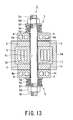
- Fig. 13 is a sectional view illustrating a thermoelectric generator according to the present embodiment. Further, it is to be noted that the basic structure or configuration of the fifth embodiment is the same as that of the fourth embodiment, and hence, the same reference numerals or characters are assigned to components or members corresponding to those of the first to fourth embodiments, and the duplicate description is omitted herein.
- the present embodiment specifies a structure in which two units of the thermoelectric generator are disposed facing each other on a parallel surface of a rectangular passage where the heat exchange fin is formed on the high temperature medium side of the high temperature member.
- the thermoelectric generator 1 of the present embodiment has approximately the same configuration as that of the fourth embodiment except the fastening configuration of the tie rod 5c.
- the configuration is made such that the fin 16 is formed on the high temperature medium side of the high temperature member 3 so as to perform heat exchanging operation at high performance.
- the high temperature member 3 includes a circular or rectangular tube-shaped through-hole 3b perpendicular to a surface on which the thermoelectric module 2 is mounted.
- the tie rod 5c is inserted through the inside of the through-hole 3b, and an anti-radiation plate 17 is provided between the through-hole 3b and the tie rod 5c so as to reduce thermal energy loss.
- a heat insulating material 14 may be filled therebetween.
- the through-hole 3b also acts as a roll of a fin, the performance will be improved.
- the temperature of the tie rod 5c is difficult to increase. Consequently, during the operation, the amount of thermal expansion of the high temperature member 3 is larger than that of the tie rod 5c, and contrary to the fourth embodiment, the fastening force by the pressing member 5 is applied in a direction of increasing the fastening force.
- the fastening force increases the adhesion between the high temperature member 3 and the thermoelectric module 2, and reduces the contact thermal resistance between the high temperature member 3 and the thermoelectric module 2.
- the spring member 5a is mounted on both ends of the tie rod 5c, it may be mounted on one end side thereof.
- thermoelectric module 2 and the low temperature member 4 are disposed opposing and in parallel to a surface of the high temperature member 3 and are fastened by the tie rod 5c via the pressing member 5, a uniform contact surface pressure can be provided between the high temperature member 3 and the thermoelectric module 2, and between the thermoelectric module 2 and the low temperature member 4.
- the present embodiment it is not necessary to alternately tighten the nuts as a method of adjusting the fastening force to a plurality of tie rods 5c, and hence, the present embodiment is excellent in assembling performance.
- thermoelectric generator can provide an efficient conversion from thermal energy to electrical energy with a compact structure at high performance, and being excellent in structural reliability and versatility.
Landscapes
- Measuring Temperature Or Quantity Of Heat (AREA)
- Investigating Or Analyzing Materials Using Thermal Means (AREA)
- Thermotherapy And Cooling Therapy Devices (AREA)
- General Electrical Machinery Utilizing Piezoelectricity, Electrostriction Or Magnetostriction (AREA)
Abstract
A thermoelectric generator includes: a high temperature member which conducts thermal energy of a high temperature medium; a low temperature member which is provided on a side opposing to the high temperature medium of the high temperature member and is provided with a low temperature medium passage therein; a thermoelectric module which is sandwiched between the high temperature member and the low temperature member and carries out a thermoelectric conversion element converting a thermal energy to an electrical energy using a temperature difference between the high temperature medium and the low temperature medium supplied to the low temperature medium passage, and at least one tie rod fastening between the low temperature member and the high temperature member.
Description
- The present invention relates to a thermoelectric generator which uses a thermoelectric module to convert thermal energy to electrical energy using a temperature difference, and more particularly, to a thermoelectric generator capable of efficiently generating electricity by a wide use of high-temperature fluids or other various kinds of heat sources emitting radiant heat.
- In recent years, with advancement of industry and science and technology, an amount of energy consumed by humans has been increased unprecedentedly at an accelerated speed. As a result, an inconvenient matter of global warming due to greenhouse gases such as CO2 is emerging.
- In light of the above fact, in order to suppress the generation of greenhouse gases as much as possible, there is currently expected the commercialization of a power generator which recovers high-temperature thermal energy discarded unused from not only various industries such as gas incinerators and thermal power plants but also internal combustion engines of automobiles and the like as electrical energy as much as possible.
- As a power generator recovering thermal energy as electrical energy, there has been well known a power generation technique using thermoelectric elements. The thermoelectric element uses the Seebeck effect where a temperature difference is given between both ends of a metal or a semiconductor to thereby produce a potential difference between a high temperature portion and a low temperature portion. The thermoelectric element has such characteristics as that the larger the temperature difference is the larger the power generation. In general, thermoelectric elements have frequently been used as a thermoelectric module incorporating a plurality of thermoelectric elements.
- As a thermoelectric generator using such a thermoelectric module, there have been conventionally proposed various kinds of configurations thereof for the purpose of transferring the exhaust gas thermal energy of an internal combustion engine to the electrical energy, where a thermoelectric module is held in a pressed state by being tightened with bands or the like, a high temperature member and a low temperature member are made in contact with a high temperature surface and a low temperature surface of the thermoelectric module respectively, and according to this configuration, the thermal energy is converted to the electrical energy (for example, see Patent Document 1: Japanese Patent Application Laid-Open Publication No.
2005-223131 2004-208476
Most of the conventionally proposed thermoelectric generators including the aforementioned thermoelectric generator relate to the configuration where a high temperature fluid as a heat source is made to flow through a heat transfer tube provided in the center portion of the generator. In addition, a plurality of thermoelectric modules is fixed to the surface of the heat transfer tube in a pressed state by being collectively tightened by bands or the like from the surroundings thereof. Consequently, an uneven surface pressure occurs on the contact surface among the high temperature heat source, the thermoelectric module, and the low temperature member depending on the position of providing the thermoelectric modules and the degree of tightening the bands, which frequently affects the performance of the generator. Moreover, there is no configuration where the thermoelectric module is directly connected to the low temperature member with a member extending from the high temperature heat source. - For this reason, the generator can be installed only to the heat source having a shape of a heat transfer tube, and thus, there is a limit to the application of the generator to many heat sources of high temperature fluids or heat sources emitting radiant heat being used in various industrial facilities.
- In view of the above circumstances, the present invention has been made, and an object of the present invention is to provide a thermoelectric generator capable of providing an efficient conversion from thermal energy to electrical energy by being provided directly to or slightly spaced from an existing high temperature heat source in various kinds of industrial facilities, having a compact and high performance power generation function, and being excellent in structural health and operability such as mounting and maintenance.
- In order to achieve the above object, the present invention provides a thermoelectric generator comprising: a high temperature member which conducts thermal energy of a high temperature medium; a low temperature member which is provided on a side opposing to the high temperature medium of the high temperature member and is provided with a low temperature medium passage thereinside; a thermoelectric module which is sandwiched between the high temperature member and the low temperature member and carries out a thermoelectric conversion element converting thermal energy to electrical energy using a temperature difference between the high temperature medium and the low temperature medium supplied to the low temperature medium passage; and at least one tie rod fastening between the low temperature member and the high temperature member.
- Further, in the present invention mentioned above, the high temperature member may have two surfaces in parallel to each other, the thermoelectric module and the low temperature member are provided on each of the parallel surfaces of the high temperature member, and the low temperature members are fastened together by the tie rod.
- In addition, it may be desirable that the present invention should be configured such that the high temperature member has two parallel surfaces and a through-hole connecting the two parallel surfaces, the thermoelectric module and the low temperature member are provided on each of the parallel surfaces of the high temperature member, and the low temperature members are fastened together by the tie rod.
- Furthermore, the present invention may be configured so that the low temperature member, the thermoelectric module, and the tie rod are combined into one unit, and a plurality of the units are arranged on the high temperature member.
- Still furthermore, it may be desired that, as a member for fastening the low temperature member and the high temperature member with the tie rod, a plurality of spring members whose contact portion forms a line contact are provided.
- Still furthermore, the present invention may be configured so that the low temperature member includes a base material and a passage material forming a passage, and a rigidity of the passage material is equal to or greater than a rigidity of the base material.
- In addition, the base material may be formed with an element selected from aluminum, copper, iron, molybdenum, titanium, nickel, tin, zirconium, zinc, and magnesium, or a compound or an alloy containing any one of the above elements as its main component.
- In addition, the thermoelectric conversion element may be a direct thermoelectric conversion semiconductor formed with at least three or more elements selected from rare earth element, uranium, thorium, plutonium, cobalt, nickel, iron, rhodium, ruthenium, palladium, platinum, antimony, titanium, zirconium, hafnium, tin, silicon, manganese, zinc, boron, carbon, nitrogen, oxygen, gallium, germanium, indium, vanadium, niobium, barium, magnesium, chromium, tantalum, molybdenum, and aluminum.
- Furthermore, in the present invention, the direct thermoelectric conversion semiconductor may have a crystal structure of any one of a skutterudite structure, a filled skutterudite structure, a Heusler structure, a half-Heusler structure, and a clathrate structure.
- In addition, in the present invention mentioned above, the crystal structure of the direct thermoelectric conversion semiconductor may be at least one or a compound or a mixture or a solid solution of a layered complex oxide of cobalt and a substance selected from copper oxide, carbon, boron, sodium, and calcium; aluminum nitride; uranium nitride; silicon nitride; molybdenum disulfide; a thermoelectric conversion material containing cobalt antimonide compound having a skutterudite crystal structure as the main phase; a thermoelectric conversion material containing clathrate compound as the main phase; and a thermoelectric conversion material containing half-Heusler compound as the main phase.
- According to the present invention of the characters mentioned above, there is provided a thermoelectric generator capable of providing an efficient conversion from the thermal energy to the electrical energy with a compact structure at high performance power generation function, and being excellent in structural health and operability such as mounting and maintenance.
-
- [
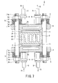
Fig. 1 ] is a sectional view illustrating a thermoelectric generator according to a first embodiment of the present invention (sectional view along line I-I inFig. 2 ). - [
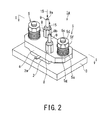
Fig. 2 ] is a perspective view illustrating a unit of the thermoelectric generator according to the first embodiment of the present invention. - [
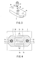
Fig. 3 ] is a perspective view illustrating a low temperature member of the thermoelectric generator according to the first embodiment of the present invention. - [
Fig. 4 ] is a sectional view illustrating a passage configuration of a thermoelectric module of the thermoelectric generator according to the first embodiment of the present invention (sectional view along line IV-IV inFig. 1 ). - [
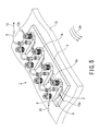
Fig. 5 ] is an entire structural view illustrating the thermoelectric generator according to the first embodiment of the present invention. - [
Fig. 6 ] is a sectional view illustrating a thermoelectric generator according to a second embodiment of the present invention. - [
Fig. 7 ] is a sectional view illustrating a thermoelectric generator according to a third embodiment of the present invention. - [
Fig. 8 ] is a perspective view illustrating a unit of a thermoelectric generator according to a fourth embodiment of the present invention. - [
Fig. 9 ] is a sectional view along line IX-IX inFig. 8 . - [
Fig. 10 ] is a perspective view illustrating a low temperature member of the thermoelectric generator according to the fourth embodiment of the present invention. - [
Fig. 11 ] is a sectional view illustrating a passage configuration of a thermoelectric module of the thermoelectric generator according to the fourth embodiment of the present invention (sectional view along line XI-XI inFig. 9 ). - [
Fig. 12 ] is an entire structural view illustrating the thermoelectric generator according to the fourth embodiment of the present invention. - [
Fig. 13 ] is a sectional view illustrating a thermoelectric generator according to a fifth embodiment of the present invention. - Hereinafter, embodiments of the thermoelectric generator according to the present invention will be described with reference to the accompanying drawings.
- As illustrated in
Figs. 1 and2 , a thermoelectric generator 1 of the present embodiment includes ahigh temperature member 3 which receives heat by conduction of thermal energy supplied from a heat source (not illustrated), athermoelectric module 2 which receives heat with one surface (bottom surface) thereof being in contact with thehigh temperature member 3, and alow temperature member 4 which cools the other surface of thethermoelectric module 2 by flowing alow temperature medium 15 supplied from a cooling facility (not illustrated) thereinside. - The
high temperature member 3 is, for example, of a flat plate shape, a plurality of (two in the figure)screw holes 3a are formed on one side surface thereof, and atie rod 5c is inserted into eachscrew hole 3a by screwing the tie rod. Further, thetie rod 5c may be mounted on thehigh temperature member 3 by bolt fastening or welding. Moreover, a high temperature wall, not illustrated, incorporating a heat source may be directly used as thehigh temperature member 3, and the tie rod may be directly connected to thehigh temperature member 3. - The
thermoelectric module 2 is of a rectangular plate shape having a predetermined thickness and is disposed in contact with one side surface (upper surface inFig. 1 ) of thehigh temperature member 3 to be heated in contact with thehigh temperature member 3. In addition, alow temperature member 4 is, for example, configured in such a manner that a plurality of plates having grooves formed by mechanical processing is laminated and each plate is joined by brazing to form a rectangular shape. Thelow temperature member 4 is disposed in contact with the outer surface (upper surface inFig. 1 ) of thethermoelectric module 2. -
Fig. 3 illustrates a mounting structure in which a joint 8 is mounted on thelow temperature member 4. As illustrated inFig. 3 , a cooling medium entrance/exit portion 4b of the lowtemperature medium passage 4a is formed in an outer surface of thelow temperature member 4, for example, as a screw hole, and is mounted in such a manner that the joint 8 for piping connection is inserted by screwing thejoint 8. -
Fig. 4 is a sectional view along line IV-IV inFig. 1 , and illustrates a configuration of the lowtemperature medium passage 4a of thelow temperature member 4 and the like. As illustrated inFig. 4 , thelow temperature member 4 includes the lowtemperature medium passage 4a which is formed, for example, as a serpentine passage, to supply a low temperature medium from a cooling facility (not illustrated). Both ends of the lowtemperature medium passage 4a formjoint mounting positions joints thermoelectric module 2 illustrated inFigs. 1 and2 is in contact with thelow temperature member 4 and thethermoelectric module 2 is cooled from the outer surface side of the thermoelectric generator. - As illustrated in
Fig. 1 , the thermoelectric generator 1 includes apressing member 5. The pressingmember 5 has a thermal expansion absorption function to press thelow temperature member 4 against the high temperature member side. More specifically, thepressing member 5 has atie rod 5c to whichscrew portions screw portion 5e on one end side of thetie rod 5c is screwed into ascrew hole 3a formed in a surface of thehigh temperature member 3. Moreover, around thetie rod 5c, there are provided awasher 5g, aspring member 5a such as a disc spring, which is an elastic member formed by laminating a plurality of spring plates so as to press thelow temperature member 4, and a flangedsleeve 5f serving as a guide of thespring member 5a. These components are fastened by a nut 5d screwed into ascrew portion 5h provided on the other end side of thetie rod 5c. - As described above, the present embodiment includes a plurality of (two)
tie rods 5c fastening thelow temperature member 4 and thehigh temperature member 3. The present embodiment is configured such that thesleeve 5f serving as a guide of thespring member 5a and thewasher 5g are provided on both end portions of thespring member 5a so as to elastically press thethermoelectric module 2, theheat insulating material 14, and thelow temperature member 4. - In this configuration, during operation, a difference between a thermal expansion coefficient and a difference in temperature distribution causes a thermal expansion difference to occur between the
tie rod 5c and a thermal exchange unit composed of thehigh temperature member 3, thethermoelectric module 2, and thelow temperature member 4. According to an increase in temperature, although the fastening force between thetie rods 5c and the thermal exchange unit is lost due to the thermal expansion difference, thespring member 5a is pressed in advance and thus can prevent the loss of the fastening force therebetween. -
Fig. 5 illustrates a configuration of a thermoelectric generator 1, where the configuration ofFig. 1 including thelow temperature member 4, thethermoelectric module 2, thetie rod 5c, and the like is treated as one unit ofthermoelectric generator unit 1a, and a plurality ofunits 1a is mounted on thehigh temperature member 3 as the plurality of units. The thermoelectric generator 1 is configured by evenly mounting fourthermoelectric generator units 1a on thehigh temperature member 3, and, for example, is mounted on an existinghigh temperature wall 12. The thermoelectric generator 1 generates power by receiving ahigh temperature convection 20 and supplies the generated power to an outside portion through a common electrical wiring 13 (plus (+)electrode side 13a and minus (-)electrode side 13b). Further, it is to be noted that the number of units may be adjusted depending on the size of thehigh temperature wall 12 and the amount of power generation. It is also noted that thermoelectric generator 1 may be mounted on thehigh temperature wall 12 by welding or by hastening, or if possible, thetie rod 5c thereof may be directly joined to thehigh temperature wall 12. - Herein, with reference to
Figs. 1 to 5 , the configuration of the present embodiment will be further described in detail.
As illustrated in these figures, the thermoelectric generator 1 of the present embodiment is configured such that thehigh temperature member 3 and thelow temperature member 4 are pressed by thespring member 5a such as a disc spring for absorbing the thermal expansion. According to this configuration, the amount of screwing thenut 5d can be adjusted so as to adjust the force of pressing thethermoelectric module 2 sandwiched between thehigh temperature member 3 and thelow temperature member 4 through thepressing member 5 including thespring member 5a and the like. A reaction force from thespring member 5a is received by thetie rod 5c. - In this manner, the pressing
member 5 having a function to generate the pressure load and absorb the thermal expansion presses thethermoelectric module 2 in contact with thehigh temperature member 3 against thelow temperature member 4 by a predetermined force. This pressure force increases the adhesion between thehigh temperature member 3 and thethermoelectric module 2, and thus, reduces the contact thermal resistance between thehigh temperature member 3 and thethermoelectric module 2. Thenut 5d is screwed into thescrew portion 5h formed on the upper end of thetie rod 5c. Accordingly, a rotation of thenut 5d can be converted into a movement in a perpendicular direction with respect to thespring member 5a. Therefore, the bending amount or pressing force of thespring member 5a can be adjusted with a high precision. - During high temperature operation, the
spring member 5a receives heat from thehigh temperature member 3 through thetie rod 5c. The disc spring of thespring member 5a is in line contact with thewasher 5f, thus suppressing an increase in temperature thereof. Further, the disc spring of thespring member 5a is in line contact with thewasher 5g in contact with thelow temperature member 4, and thus, only a small amount of heat is transferred to thelow temperature member 4. - Moreover, by maintaining the temperature of the
spring member 5a to be low, the spring constant can be prevented from lowering. Further, the amount of heat escaping to thespring member 5a and thelow temperature member 4 can be reduced, thus effectively reducing the thermal energy loss. Further, the temperature of thetie rod 5c is assumed to be a high temperature of 400°C or higher depending on the facility used as the heat source, and thus, it is required for thetie rod 5c to be made of a material having creep strength. - In this viewpoint, it is desirable that the material of the
tie rod 5c should be, for example, an austenitic stainless steel such as SUS 316 and SUS 304; a chromium molybdenum steel such as 21/4Cr-1Mo, 9Cr-1Mo, and improved 9Cr-1Mo; a high nickel alloy such as NCF 600; or an oxide dispersion strengthened steel. Further, if a material having a low thermal expansion coefficient is used for thetie rod 5c, the amount ofspring member 5a may be reduced. - Since the
tie rod 5c passes through a tie rod through-hole 4c formed in thelow temperature member 4, the mutual distance becomes relatively small. In order to reduce the thermal energy loss, ananti-radiation plate 17 is inserted between thetie rod 5c and thelow temperature member 4. It is desirable that theanti-radiation plate 17 should be made of a material having low radiation, and thus a thin metal plate such as stainless steel, carbon steel, or aluminum alloy should be used. As the shape of theanti-radiation plate 17, a tube-shaped thin plate is easy to be assembled, and a plurality of layered tube-shaped thin plates has an insulation superior to a single layer of a tube-shaped thin plate. - In order to suppress the thermal energy loss, a
heat insulating material 14 is provided on a portion of thehigh temperature member 3 which is not in contact with thethermoelectric module 2. The material of thelow temperature member 4 is required to have strength against a temperature of about 150°C, low gravity to be light weight, corrosion resistance to thelow temperature medium 15, and high thermal conductivity. Consequently, it is desirable to apply aluminum alloy such as A6061, for example, on which anodizing (alumite treatment) is performed. If further light weight, strength, and corrosion resistance are strongly required, titanium alloy may be effective. On the contrary, if light weight is not required, austenitic stainless steel such as SUS 304 may be used. Moreover, it is effective that the base material is formed of aluminum alloy and an annealed stainless steel pipe is buried into the passage by HIP processing so as to improve corrosion resistance and reduce weight. Furthermore, it is to be noted that the low temperature member includes the base material and a passage material forming the passage, and the rigidity of the passage material is equal to or greater than the rigidity of the base material. - In addition, the base material may be formed of an element selected from aluminum, copper, iron, molybdenum, titanium, nickel, tin, zirconium, zinc, magnesium, or a compound or an alloy containing any one of the above elements as its main component.
- The low
temperature medium passage 4a is formed inside thelow temperature member 4. A joint 8 is mounted on the entrance/exit 4b of thelow temperature medium 15 provided on the upper surface of thelow temperature member 4. AlthoughFig. 3 illustrates a configuration in which thejoint 8 of thelow temperature medium 15 is mounted on the upper surface of thelow temperature member 4, the joint 8 may be mounted on a side surface of thelow temperature member 4. Apipe 9 such as a steel pipe, a copper tube, or a fluororesin tube is connected to the joint 8 so as to flow thelow temperature medium 15 across a plurality oflow temperature members 4. Here, if thelow temperature member 4 is made by HIP processing by applying aluminum alloy and stainless steel pipe, the stainless steel pipe may be made to extend from thelow temperature member 4. Therefore, since it is not required for thelow temperature member 4 to be provided with the cooling medium entrance/exit portion 4b, the connection of thepipe 9 can be easily done. - According to the thermoelectric generator 1 of the present embodiment, as described above, the configuration of
Fig. 2 is treated as one unit, and on the other hand, as illustrated inFig. 5 , a plurality of units (e.g., four units) are consecutively mounted on the surface of thehigh temperature member 3. It should be noted that the number of units is not limited to these structures, and a further number of units may be mounted as needed so as to increase the amount of power generation. - The
low temperature medium 15 is supplied to thelow temperature member 4 of each unit through thepipe 9 via an entrance header (not illustrated). Thelow temperature medium 15 flows through across a plurality oflow temperature member 4 of each unit. Thelow temperature medium 15 heated during the power generation is returned to an exit header (not illustrated) through thepipe 9. - According to the structure mentioned above, the pressing
member 5 can adjust the bending amount of thespring member 5a so as to press eachthermoelectric module 2 sandwiched between thehigh temperature member 3 and thelow temperature member 4 by a predetermined force, and to hence effectively cause a temperature difference to occur on the upper and lower surfaces of thethermoelectric module 2. - Further, although the temperature difference causes a thermal expansion difference to occur between the
pressing member 5 and thehigh temperature member 3, thethermoelectric module 2 and thelow temperature member 4, the pressingmember 5 is provided with thespring member 5a, and the initial amount of fastening by thespring member 5a can be set at assembly so as to generate an appropriate pressing force to thethermoelectric module 2 during normal operation and so as not to generate an excessively small pressing force enough to undermine the performance of thethermoelectric module 2 even under a maximum temperature condition. Therefore, the soundness of thethermoelectric module 2 can be maintained at the assembling time. - In a case of mounting the thermoelectric generator 1 of the present embodiment on an existing
high temperature wall 12 in various industrial plants and the like, a jig having a good adhesive performance to the surface condition of thehigh temperature wall 12 and thethermoelectric module 2, a high thermal conductivity may be provided between thehigh temperature member 3, and in addition, thethermoelectric module 2 and may be fixed by volt fastening or welding. - Moreover, if possible, the thermoelectric generator 1 may be directly mounted on the
high temperature wall 12 instead of thehigh temperature member 3. Further, if thehigh temperature wall 12 has a bad surface state such as a rough surface, thehigh temperature wall 12 and thehigh temperature member 3 may be spaced apart by a predetermined distance, and the radiant heat may be used as the heat source. - Further, the
high temperature member 3 is frequently exposed to corrosive fluids, and as described above, the temperature is assumed to be a high temperature of 400°C or higher. Therefore, it is required for the materials to have corrosion resistance and high temperature strength. In addition, welding and machining are required, and it is hence desirable that the material of thehigh temperature member 3 is chromium molybdenum steel, ferritic stainless steel, or austenitic stainless steel. - In order to reduce the contact thermal resistance between the
high temperature member 3 and thethermoelectric module 2 or to equalize the temperature distribution, a heat transfer sheet may be provided therebetween. Here, it is desirable for the material of the heat transfer sheet to be a material having heat resistance and a large thermal conductivity such as graphite (black lead), copper, precious metal such as copper alloy and silver, and paint such as ceramic-based adhesive and putty. Furthermore, in order to reduce the contact thermal resistance between thethermoelectric module 2 and thelow temperature member 4 or to equalize the temperature distribution,silicon grease 11 and the heat transfer sheet may be provided therebetween. - Further, a thermoelectric conversion element, not illustrated, incorporated in the thermoelectric module may be a direct thermoelectric conversion semiconductor formed of at least three or more elements selected from rare earth element, uranium, thorium, plutonium, cobalt, iron, rhodium, ruthenium, palladium, platinum, nickel, antimony, titanium, zirconium, hafnium, nickel, tin, silicon, manganese, zinc, boron, carbon, nitrogen, oxygen, gallium, germanium, indium, vanadium, niobium, barium, magnesium, chromium, tantalum, molybdenum, aluminum.
- In addition, the crystal structure of the direct thermoelectric conversion semiconductor may contain any one or a compound or a mixture or a solid solution of a skutterudite structure, filled skutterudite structure, Heusler structure, half-Heusler structure, clathrate structure as its main component.
- In addition, direct thermoelectric conversion semiconductor may be at least one or a compound or a mixture or a solid solution of a layered complex oxide of cobalt and a substance selected from copper oxide, carbon, boron, sodium, and calcium; aluminum nitride; uranium nitride; silicon nitride; molybdenum disulfide; a thermoelectric conversion material containing cobalt antimonide compound having a skutterudite crystal structure as the main phase; a thermoelectric conversion material containing clathrate compound as the main phase; and a thermoelectric conversion material containing half-Heusler compound as the main phase.
- As described above, according to the present embodiment, the
low temperature member 4, which is load-transferred by the pressingmember 5 having a function to generate pressure load and absorb thermal expansion, is pressed to thethermoelectric module 2 being in contact with thehigh temperature member 3 by a predetermined force. This pressure force increases the adhesion between thehigh temperature member 3 and thethermoelectric module 2, thus reducing the contact thermal resistance between thehigh temperature member 3 and thethermoelectric module 2. Furthermore, since thenut 5d is screwed into thescrew portion 5h formed on the upper end of thetie rod 5c, the rotation of thenut 5d can be converted to a movement in a perpendicular direction with respect to thespring member 5a. Therefore, the bending amount or pressing force of thespring member 5a can be adjusted with a good precision. Further, during operation, a difference between a thermal expansion coefficient and a difference in temperature distribution causes a thermal expansion difference to occur between thetie rod 5c and the thermal exchange unit consisting of thehigh temperature member 3, thethermoelectric module 2, and thelow temperature member 4. However, thespring member 5a is pressed in advance by an amount more than thermal expansion, and hence, thus the loss of the fastening force can be prevented by the thermal expansion difference. Still furthermore, since the material of thelow temperature member 4 has low gravity, corrosion resistance, and high thermal conductivity, the present embodiment can provide a thermoelectric generator capable of providing an efficient conversion from thermal energy to electrical energy, having a compact and high performance, and being excellent in structural soundness. - The second embodiment of the present invention will be described with reference to
Fig. 6. Fig. 6 is a sectional view illustrating a thermoelectric generator according to the present second embodiment. It is to be noted that the basic structure of this second embodiment is the same as that of the first embodiment, and thus, the same reference numerals or characters are assigned to components or like corresponding to those of the first embodiment, and the duplicate description is omitted herein.
The present embodiment focuses on a configuration in which aheat exchange fin 16 is formed on a high temperature medium side of thehigh temperature member 3. - More specifically, as shown in
Fig. 6 , a thermoelectric generator 1 of the present embodiment has the same structure or configuration as that of the first embodiment except that a plurality offins 16 are formed on the bottom surface side of thehigh temperature member 3 in the drawing. Thefins 16 are mounted on a pipe and a ractor wall through which a high temperature fluid flows so as to perform heat exchange. Thus, a high performance power generation can be provided. - Further, although the
high temperature member 3 is, for example, of a flat plate shape, as illustrated inFig. 6 , the shape thereof is not limited thereto, and for example, thehigh temperature member 3 may form to provide a circular shape having curvature so as to be applicable to a circular pipe. In addition, a plurality of generators of the present embodiment may be connected in a circular tube shaped or rectangular tube shaped array to form a pipe arrangement which is connected to a pipe arrangement through which the high temperature fluid flows. - According to the above second embodiment, a thermoelectric generator cam provide an efficient conversion from thermal energy to electrical energy with a compact and simple structure at high performance, and being excellent in structural reliability and versatility.
- The third embodiment of the present invention will be described hereunder with reference to
Fig. 7. Fig. 7 is a sectional view illustrating a thermoelectric generator according to the third embodiment. It is to be noted that the basic configuration of the third embodiment is the same as those of the first and second embodiments, and hence, the same reference numerals or characters are assigned to components or like corresponding to those of the first and second embodiments, and the duplicate description is omitted herein. - The present embodiment shows a structure or configuration in which two units of the thermoelectric generator are disposed facing each other on a parallel surface of a
rectangular passage 20 where theheat exchange fin 16 is formed on a high temperature medium side of thehigh temperature member 3. - As illustrated in
Fig. 7 , the thermoelectric generator 1 of the present embodiment has approximately the same configuration as that of the second embodiment except the fastening structure of thetie rod 5c. In the illustrated structure, thefin 16 is formed on the high temperature medium side of thehigh temperature member 3 so as to perform high performance heat exchange. Further, although thehigh temperature member 3 is of a rectangular shape as illustrated inFig. 7 , this shape is not limited thereto. In addition, although the thermoelectric generator unit is mounted on a flat surface, the high temperature medium passage may be of a circular shape. In this case, the pipe for introducing the high temperature medium should be formed to have a circular shape for easy connection. - According to the present embodiment, since the
tie rod 5c is not directly fastened to thehigh temperature member 3, the temperature of thetie rod 5c is hard to increase. Consequently, during the operation, the amount of thermal expansion of thehigh temperature member 3 is larger than that of thetie rod 5c, and contrary to the second embodiment, the fastening force by the pressingmember 5 is applied in a direction of increasing the fastening force. The fastening force increases the adhesion between thehigh temperature member 3 and thethermoelectric module 2, and reduces the contact thermal resistance between thehigh temperature member 3 and thethermoelectric module 2. Further, in the structure ofFig. 7 , although thespring member 5a is mounted on both ends of thetie rod 5c, it may be mounted on one end side thereof. - The
thermoelectric module 2 and thelow temperature member 4 are disposed opposing and in parallel to a surface of thehigh temperature member 3, and are fastened by thetie rod 5c via the pressingmember 5. Thus, a uniform contact surface pressure can be provided between thehigh temperature member 3 and thethermoelectric module 2, and between thethermoelectric module 2 and thelow temperature member 4. - As described above, according to the present third embodiment, the thermoelectric generator can provide an efficient conversion from thermal energy to electrical energy with a compact structure at high performance, and being excellent in structural reliability and versatility.
- The fourth embodiment of the present invention will be described hereunder with reference to
Figs. 8 to 12 .Fig. 8 is a perspective view illustrating a unit of a thermoelectric generator according to the present fourth embodiment.Fig. 9 is a sectional view illustrating the thermoelectric generator according to the present embodiment (sectional view taken along line IX-IX inFig. 8 ). It is to be noted that the basic structure or configuration of the fourth embodiment is the same as that of the first embodiment, and the same reference numerals or characters are assigned to components or members corresponding to those of the first embodiment, and the duplicate description is omitted herein. - As illustrated in
Figs. 8 and 9 , according to the thermoelectric generator 1 of the present fourth embodiment, arectangular hole 4c is provided commonly, for example, in central portions of thethermoelectric module 2 and thelow temperature member 4, and the number oftie rods 5c is reduced to one. In other words, reduction of the number of thepressing members 5 having a function to generate pressure load and absorb thermal expansion to one portion can save the space of mounting area of the thermoelectric generator 1, thereby increasing the freedom of mounting place. Moreover, the amount of fastening thespring member 5a can be controlled at one position, thereby increasing the operability and structural reliability. -
Fig. 10 illustrates a structure of mounting the joint 8 and thepipe 9 on thelow temperature member 4. As illustrated inFig. 10 , the entrance andexit 4b of the lowtemperature medium passage 4a is formed as a screw hole, for example, on an outer surface of thelow temperature member 4, and the joint 8 for connecting thepipe 9 is screwed to be mounted thereto. A rectangular hole through which thetie rod 5c can pass is provided in the center of the low temperature member, and this hole may be formed in a circular shape. -
Fig. 11 is an illustration of the lowtemperature medium passage 4a and portions associated therewith in thelow temperature member 4. As illustrated inFig. 11 , thelow temperature member 4 includes the lowtemperature medium passage 4a which supplies thelow temperature medium 15 from a cooling facility (not illustrated). The lowtemperature medium passage 4a is formed, for example, as a quadrangular annular passage. Further, the lowtemperature medium passage 4a may be formed as a serpentine passage. When the outer surface of thethermoelectric module 2 illustrated inFig. 8 comes into contact with thelow temperature member 4, thethermoelectric module 2 is cooled from the outer surface side of the generator. -
Fig. 12 is a perspective view showing an entire configuration of the thermoelectric generator according to the present embodiment. As illustrated inFig. 12 , according to the present embodiment, four thermoelectric generator units are evenly mounted on thehigh temperature member 3 and are connected by an electrical wiring 13. The example illustrates that thehigh temperature member 3 receivesradiant heat 21 from a heat source (not illustrated). According to the structure of the present embodiment mentioned above, the main components or members of the thermoelectric generator 1 can be mounted on a portion defended or cooled by a common heat insulated wall as well as the surroundings of a blast furnace or an incinerator in a steel plant with good operability. - As described above, according to the present embodiment, the thermoelectric generator can provide an efficient conversion from the thermal energy to the electrical energy, having a compact structure at high performance, and being excellent in structural health and operability.
- The fifth embodiment of the present invention will be described with reference to
Fig. 13. Fig. 13 is a sectional view illustrating a thermoelectric generator according to the present embodiment. Further, it is to be noted that the basic structure or configuration of the fifth embodiment is the same as that of the fourth embodiment, and hence, the same reference numerals or characters are assigned to components or members corresponding to those of the first to fourth embodiments, and the duplicate description is omitted herein.
The present embodiment specifies a structure in which two units of the thermoelectric generator are disposed facing each other on a parallel surface of a rectangular passage where the heat exchange fin is formed on the high temperature medium side of the high temperature member. - As illustrated in
Fig. 13 , the thermoelectric generator 1 of the present embodiment has approximately the same configuration as that of the fourth embodiment except the fastening configuration of thetie rod 5c. The configuration is made such that thefin 16 is formed on the high temperature medium side of thehigh temperature member 3 so as to perform heat exchanging operation at high performance. Thehigh temperature member 3 includes a circular or rectangular tube-shaped through-hole 3b perpendicular to a surface on which thethermoelectric module 2 is mounted. Thetie rod 5c is inserted through the inside of the through-hole 3b, and ananti-radiation plate 17 is provided between the through-hole 3b and thetie rod 5c so as to reduce thermal energy loss. Further, instead of theanti-radiation plate 17, aheat insulating material 14 may be filled therebetween. Further, since the through-hole 3b also acts as a roll of a fin, the performance will be improved. - Since, the
tie rod 5c is not directly contacted to thehigh temperature member 3, the temperature of thetie rod 5c is difficult to increase. Consequently, during the operation, the amount of thermal expansion of thehigh temperature member 3 is larger than that of thetie rod 5c, and contrary to the fourth embodiment, the fastening force by the pressingmember 5 is applied in a direction of increasing the fastening force. The fastening force increases the adhesion between thehigh temperature member 3 and thethermoelectric module 2, and reduces the contact thermal resistance between thehigh temperature member 3 and thethermoelectric module 2. Further, in the structure ofFig. 13 , although thespring member 5a is mounted on both ends of thetie rod 5c, it may be mounted on one end side thereof. - According to the present embodiment, since the
thermoelectric module 2 and thelow temperature member 4 are disposed opposing and in parallel to a surface of thehigh temperature member 3 and are fastened by thetie rod 5c via the pressingmember 5, a uniform contact surface pressure can be provided between thehigh temperature member 3 and thethermoelectric module 2, and between thethermoelectric module 2 and thelow temperature member 4. - Moreover, according to the present embodiment, it is not necessary to alternately tighten the nuts as a method of adjusting the fastening force to a plurality of
tie rods 5c, and hence, the present embodiment is excellent in assembling performance. - As described above, according to this embodiment, the thermoelectric generator can provide an efficient conversion from thermal energy to electrical energy with a compact structure at high performance, and being excellent in structural reliability and versatility.
Claims (10)
- A thermoelectric generator comprising:a high temperature member which conducts thermal energy of a high temperature medium;a low temperature member which is provided on a side opposing to the high temperature medium of the high temperature member and is provided with a low temperature medium passage therein;a thermoelectric module which is sandwiched between the high temperature member and the low temperature member and carries out a thermoelectric conversion element converting a thermal energy to an electrical energy using a temperature difference between the high temperature medium and the low temperature medium supplied to the low temperature medium passage; andat least one tie rod fastening between the low temperature member and the high temperature member.
- The thermoelectric generator according to claim 1, wherein the high temperature member has two surfaces in parallel to each other, the thermoelectric module and the low temperature member are provided on the parallel surfaces of the high temperature member, respectively, and the low temperature members are fastened to together by the tie rod.
- The thermoelectric generator according to claim 1, wherein the high temperature member has two parallel surfaces and a through-hole connecting the two parallel surfaces, the thermoelectric module and the low temperature member are provided on each of the parallel surfaces of the high temperature member, and the low temperature members are fastened together with the tie rod.
- The thermoelectric generator according to claim 1, wherein the low temperature member, the thermoelectric module, and the tie rods are combined into one unit, and a plurality of such units are arranged on the high temperature member.
- The thermoelectric generator according to claim 1, further comprising, as a member for fastening the low temperature member and the high temperature member by means of the tie rod, a plurality of spring members whose contact portion forms a line contact are provided.
- The thermoelectric generator according to claim 1, wherein the low temperature member is composed of a base material and a passage material forming a passage, and the passage material has a rigidity equal to or greater than a rigidity of the base material.
- The thermoelectric generator according to claim 6, wherein the base material is formed of an element selected from aluminum, copper, iron, molybdenum, titanium, nickel, tin, zirconium, zinc, and magnesium, or a compound or an alloy containing any one of the above elements as main component thereof.
- The thermoelectric generator according to claim 1, wherein the thermoelectric conversion element is a direct thermoelectric conversion semiconductor formed of at least three or more elements selected from rare earth element, uranium, thorium, plutonium, cobalt, nickel, iron, rhodium, ruthenium, palladium, platinum, antimony, titanium, zirconium, hafnium, tin, silicon, manganese, zinc, boron, carbon, nitrogen, oxygen, gallium, germanium, indium, vanadium, niobium, barium, magnesium, chromium, tantalum, molybdenum, and aluminum.
- The thermoelectric generator according to claim 1, wherein the direct thermoelectric conversion semiconductor has a crystal structure of any one of a skutterudite structure, a filled skutterudite structure, a Heusler structure, a half-Heusler structure, and a clathrate structure.
- The thermoelectric generator according to claim 9, wherein the crystal structure of the direct thermoelectric conversion semiconductor is at least one or a compound or a mixture or a solid solution of a layered complex oxide of cobalt and a substance selected from copper oxide, carbon, boron, sodium, and calcium; aluminum nitride; uranium nitride; silicon nitride; molybdenum disulfide; a thermoelectric conversion material containing cobalt antimonide compound having a skutterudite crystal structure as the main phase; a thermoelectric conversion material containing clathrate compound as the main phase; and a thermoelectric conversion material containing half-Heusler compound as the main phase.
Applications Claiming Priority (2)
| Application Number | Priority Date | Filing Date | Title |
|---|---|---|---|
| JP2007259054A JP2009088408A (en) | 2007-10-02 | 2007-10-02 | Thermoelectric generator |
| PCT/JP2008/067731 WO2009044728A1 (en) | 2007-10-02 | 2008-09-30 | Thermoelectric generating device |
Publications (1)
| Publication Number | Publication Date |
|---|---|
| EP2202812A1 true EP2202812A1 (en) | 2010-06-30 |
Family
ID=40526156
Family Applications (1)
| Application Number | Title | Priority Date | Filing Date |
|---|---|---|---|
| EP08835113A Withdrawn EP2202812A1 (en) | 2007-10-02 | 2008-09-30 | Thermoelectric generating device |
Country Status (5)
| Country | Link |
|---|---|
| US (1) | US20100258156A1 (en) |
| EP (1) | EP2202812A1 (en) |
| JP (1) | JP2009088408A (en) |
| CN (1) | CN101884120A (en) |
| WO (1) | WO2009044728A1 (en) |
Families Citing this family (18)
| Publication number | Priority date | Publication date | Assignee | Title |
|---|---|---|---|---|
| JP2010200520A (en) * | 2009-02-26 | 2010-09-09 | Toshiba Corp | Thermoelectric power generator |
| US20100288324A1 (en) * | 2009-05-16 | 2010-11-18 | Marc Henness | Energy conversion by exothermic to endothermic feedback |
| JP2010275976A (en) * | 2009-05-29 | 2010-12-09 | Isuzu Motors Ltd | Thermoelectric unit |
| JP2012102600A (en) * | 2010-11-15 | 2012-05-31 | Daiken Co Ltd | Building eaves |
| JP5537402B2 (en) * | 2010-12-24 | 2014-07-02 | 株式会社日立製作所 | Thermoelectric conversion material |
| US8841540B2 (en) * | 2011-08-03 | 2014-09-23 | Marlow Industries, Inc. | High temperature thermoelectrics |
| KR101372420B1 (en) * | 2012-02-10 | 2014-03-10 | (주)퓨리셈 | Thermoelectric module unit |
| JP6078412B2 (en) | 2013-04-17 | 2017-02-08 | 日立化成株式会社 | Thermoelectric power generator |
| JP6317113B2 (en) * | 2014-01-09 | 2018-04-25 | 昭和電工株式会社 | Thermoelectric converter |
| KR20160063000A (en) * | 2014-11-26 | 2016-06-03 | 현대자동차주식회사 | Thermoelectric generation device |
| CN104505457B (en) * | 2014-12-08 | 2017-07-11 | 陕西师范大学 | Thermoelectric material based on Al/CuO films and preparation method thereof |
| EP3124881A1 (en) * | 2015-07-28 | 2017-02-01 | Siemens Aktiengesellschaft | Peltier air dehumidifer for installation in a container |
| RU2606300C1 (en) * | 2015-12-30 | 2017-01-10 | Федеральное государственное бюджетное образовательное учреждение высшего профессионального образования "Московский государственный технический университет имени Н.Э. Баумана" (МГТУ им. Н.Э. Баумана) | Thermoelectric generator in internal combustion engine exhaust gases exhaust system |
| CN105978404A (en) * | 2016-05-20 | 2016-09-28 | 梁山德圣新能设备制造有限公司 | Semiconductor generator and generating device |
| CN110931374A (en) * | 2018-09-19 | 2020-03-27 | 深圳龙澄高科技环保股份有限公司 | A single-chip thermoelectric module testing device |
| JP7108651B2 (en) * | 2020-03-11 | 2022-07-28 | 株式会社小松製作所 | thermoelectric generator |
| JP7564638B2 (en) * | 2020-05-01 | 2024-10-09 | 三菱電機エンジニアリング株式会社 | Thermoelectric power generation device mounting device and mounting method |
| JP7291921B1 (en) * | 2022-08-04 | 2023-06-16 | 比呂志 佐藤 | Radiation energy utilization type power supply device and power generation method by α decay |
Family Cites Families (10)
| Publication number | Priority date | Publication date | Assignee | Title |
|---|---|---|---|---|
| JPH0448150Y2 (en) * | 1985-06-07 | 1992-11-12 | ||
| JPS62147367U (en) * | 1986-03-11 | 1987-09-17 | ||
| AU5683294A (en) * | 1992-11-27 | 1994-06-22 | Pneumo Abex Corporation | Thermoelectric device for heating and cooling air for human use |
| US6069312A (en) * | 1994-01-28 | 2000-05-30 | California Institute Of Technology | Thermoelectric materials with filled skutterudite structure for thermoelectric devices |
| US6188011B1 (en) * | 1998-01-20 | 2001-02-13 | Marlow Industries, Inc. | Thermoelectric materials fabricated from clathrate compounds and other materials which form an inclusion complex and method for optimizing selected thermoelectric properties |
| JPH11340522A (en) * | 1998-05-22 | 1999-12-10 | Ube Ind Ltd | Heat exchanger using thermoelectric conversion module |
| JP2004208476A (en) | 2002-12-26 | 2004-07-22 | Toyota Motor Corp | Waste heat power generator |
| JP4423989B2 (en) | 2004-02-05 | 2010-03-03 | トヨタ自動車株式会社 | Thermoelectric generator for internal combustion engine |
| JP2007073889A (en) * | 2005-09-09 | 2007-03-22 | Chugoku Electric Power Co Inc:The | Thermoelectric converter |
| JP2007165560A (en) * | 2005-12-13 | 2007-06-28 | Mazda Motor Corp | Waste heat power generator |
-
2007
- 2007-10-02 JP JP2007259054A patent/JP2009088408A/en not_active Abandoned
-
2008
- 2008-09-30 EP EP08835113A patent/EP2202812A1/en not_active Withdrawn
- 2008-09-30 CN CN2008801188082A patent/CN101884120A/en active Pending
- 2008-09-30 WO PCT/JP2008/067731 patent/WO2009044728A1/en not_active Ceased
- 2008-09-30 US US12/681,253 patent/US20100258156A1/en not_active Abandoned
Non-Patent Citations (1)
| Title |
|---|
| See references of WO2009044728A1 * |
Also Published As
| Publication number | Publication date |
|---|---|
| WO2009044728A1 (en) | 2009-04-09 |
| CN101884120A (en) | 2010-11-10 |
| JP2009088408A (en) | 2009-04-23 |
| US20100258156A1 (en) | 2010-10-14 |
Similar Documents
| Publication | Publication Date | Title |
|---|---|---|
| US20100258156A1 (en) | Thermoelectric generator | |
| JP5443947B2 (en) | Thermoelectric generator | |
| US20110016888A1 (en) | Thermoelectric module | |
| JP2775410B2 (en) | Thermoelectric module | |
| JP4945649B2 (en) | Thermoelectric power generation apparatus and thermoelectric power generation system | |
| JP2011176131A (en) | Thermoelectric power generation apparatus and thermoelectric power generation system | |
| JP2009194299A (en) | Thermoelectric generator | |
| JP2010245265A (en) | Thermoelectric module | |
| US20120305044A1 (en) | Thermal transfer and power generation systems, devices and methods of making the same | |
| JP5444787B2 (en) | Thermoelectric generator | |
| JP2008010764A (en) | Thermoelectric converter | |
| JP3312169B2 (en) | How to install thermoelectric generation module | |
| US3234048A (en) | Modular panel assemblies for use in thermoelectric generators | |
| JP2011192759A (en) | Thermoelectric generation system | |
| JP2008091453A (en) | Thermoelectric generator | |
| JP5970222B2 (en) | Thermoelectric generator | |
| JP2022099385A (en) | Thermoelectric generation device | |
| JP5191926B2 (en) | Thermoelectric generator | |
| JP2013069975A (en) | Thermoelectric power generation device and thermoelectric power generation method | |
| JP2006086402A (en) | Tubular thermoelectric module and thermoelectric conversion device | |
| JPH11340522A (en) | Heat exchanger using thermoelectric conversion module | |
| JP2006303037A (en) | Thermoelectric generator | |
| JP4677891B2 (en) | Heat transfer parts | |
| EP4167465B1 (en) | Thermoelectric conversion unit | |
| JP2003179274A (en) | Thermoelectric converter |
Legal Events
| Date | Code | Title | Description |
|---|---|---|---|
| PUAI | Public reference made under article 153(3) epc to a published international application that has entered the european phase |
Free format text: ORIGINAL CODE: 0009012 |
|
| 17P | Request for examination filed |
Effective date: 20100407 |
|
| AK | Designated contracting states |
Kind code of ref document: A1 Designated state(s): AT BE BG CH CY CZ DE DK EE ES FI FR GB GR HR HU IE IS IT LI LT LU LV MC MT NL NO PL PT RO SE SI SK TR |
|
| AX | Request for extension of the european patent |
Extension state: AL BA MK RS |
|
| DAX | Request for extension of the european patent (deleted) | ||
| STAA | Information on the status of an ep patent application or granted ep patent |
Free format text: STATUS: THE APPLICATION HAS BEEN WITHDRAWN |
|
| 18W | Application withdrawn |
Effective date: 20111021 |