EP2202397A2 - Throttle valve body and throttle valve device having the same - Google Patents
Throttle valve body and throttle valve device having the same Download PDFInfo
- Publication number
- EP2202397A2 EP2202397A2 EP09179672A EP09179672A EP2202397A2 EP 2202397 A2 EP2202397 A2 EP 2202397A2 EP 09179672 A EP09179672 A EP 09179672A EP 09179672 A EP09179672 A EP 09179672A EP 2202397 A2 EP2202397 A2 EP 2202397A2
- Authority
- EP
- European Patent Office
- Prior art keywords
- axis
- intake passage
- throttle valve
- downstream
- passage
- Prior art date
- Legal status (The legal status is an assumption and is not a legal conclusion. Google has not performed a legal analysis and makes no representation as to the accuracy of the status listed.)
- Granted
Links
- 238000011144 upstream manufacturing Methods 0.000 claims abstract description 25
- 239000012530 fluid Substances 0.000 claims abstract description 17
- 239000000446 fuel Substances 0.000 description 5
- 238000003915 air pollution Methods 0.000 description 2
Images



Classifications
-
- F—MECHANICAL ENGINEERING; LIGHTING; HEATING; WEAPONS; BLASTING
- F02—COMBUSTION ENGINES; HOT-GAS OR COMBUSTION-PRODUCT ENGINE PLANTS
- F02D—CONTROLLING COMBUSTION ENGINES
- F02D9/00—Controlling engines by throttling air or fuel-and-air induction conduits or exhaust conduits
- F02D9/08—Throttle valves specially adapted therefor; Arrangements of such valves in conduits
- F02D9/10—Throttle valves specially adapted therefor; Arrangements of such valves in conduits having pivotally-mounted flaps
-
- F—MECHANICAL ENGINEERING; LIGHTING; HEATING; WEAPONS; BLASTING
- F02—COMBUSTION ENGINES; HOT-GAS OR COMBUSTION-PRODUCT ENGINE PLANTS
- F02D—CONTROLLING COMBUSTION ENGINES
- F02D9/00—Controlling engines by throttling air or fuel-and-air induction conduits or exhaust conduits
- F02D9/08—Throttle valves specially adapted therefor; Arrangements of such valves in conduits
- F02D9/10—Throttle valves specially adapted therefor; Arrangements of such valves in conduits having pivotally-mounted flaps
- F02D9/1035—Details of the valve housing
- F02D9/1055—Details of the valve housing having a fluid by-pass
Definitions
- the invention relates to a throttle valve device, more particularly to a throttle valve device capable of accurately detecting temperature of intake air.
- a conventional throttle valve device is adapted for use in a vehicle (not shown).
- the throttle valve device comprises a throttle valve 2 and a sensor 3.
- the throttle valve 2 includes a throttle body 21, an intake valve 22, and a bypass valve 23.
- the throttle body 21 includes an intake passage 210, a bypass passage 211 in fluid communication with the intake passage 210, and a mounting hole 212.
- the intake valve 22 is mounted rotatably in the intake passage 210 and divides the intake passage 210 into an upstreamportion 2101 and a downstreamportion 2102.
- the bypass valve 23 divides the bypass passage 211 into an upstream section 2111 and a downstream section 2112.
- the downstream section 2112 has a downstream end 2113 that intersects the downstream portion 2102 of the intake passage 210 at a first position (A) .
- the mounting hole 212 intersects the downstream portion 2102 of the intake passage 210 at a second position (B).
- the first position (A) is spaced apart from the second position (B) .
- the mounting hole 212 is spaced apart from the bypass passage 211.
- the sensor 3 is mounted in the mounting hole 212, and has a sensing portion 31 extending into the downstream portion 2102 of the intake passage 210 and spaced apart from the downstream section 2112 of the bypass passage 211.
- the intake valve 22 When the vehicle is in an idle speed mode, the intake valve 22 is closed and the bypass valve 23 disposed in the bypass passage 211 is opened, such that the upstream section 2111 is in fluid communication with the downstream section 2112. Hence, intake air flows successively into the upstream portion 2101 of the intake passage 210, the upstream section 2111 and the downstream section 2112 of the bypass passage 211, and the downstream portion 2102 of the intake passage 210 (indicated by an arrow shown in FIG. 2 ).
- An electronic control unit (not shown) receives a temperature signal from the sensor 3 to control the amount of the intake air that enters an engine (not shown).
- the sensing portion 31 of the sensor 3 is disposed at a position spaced apart from the downstream section 2112 of the bypass passage 211 for detecting the temperature of the intake air, the temperature detected by the sensing portion 31 is not actual intake air temperature in the downstream portion 2102 of the intake passage 21.
- the ECU cannot control the amount of the intake air effectively to conform with a desired air/fuel ratio, thus resulting in inefficient fuel consumption and air pollution.
- the object of the present invention is to provide a throttle valve body that can detect actual temperature of intake air.
- a throttle valve body comprising a main body and a main valve.
- the main body includes an intake passage, a bypass passage, and a mounting hole.
- the main valve is disposed in the intake passage to divide the intake passage into an upstream portion and a downstream portion.
- the bypass passage has an upstream section that is in fluid communication with the upstream portion of the intake passage, a downstream section that extends along a first axis, and a downstream end that is in fluid communication with the downstream portion of the intake passage.
- the mounting hole extends along a second axis intersecting the first axis.
- a throttle valve device of a first preferred embodiment of the present invention comprises a throttle valve body 4 and a sensor 5.
- the throttle valve body 4 includes a main body 41 and a main valve 42.
- the main body 41 has an intake passage 411, a bypass passage 412, a mounting hole 413, and a protrusion 418 formed on an outer surface thereof.
- the main valve 42 is disposed in the intake passage 411 to divide the intake passage 411 into an upstream portion 414 and a downstream portion 415.
- the bypass passage 412 has an upstream section 416 in fluid communication with the upstream portion 414 of the intake passage 411, a downstream section 417 extending along a first axis (X), and a downstream end 419 in fluid communication with the downstream portion 415 of the intake passage 411.
- the mounting hole 413 extends along a second axis (Y) intersecting the first axis (X), is formed in the protrusion 418, and is in fluid communication with the intake passage 411.
- the first axis (X) and the second axis (Y) intersect at an intersection point 6 that is located in the downstream section 417 of the bypass passage 412 and adjacent to the downstream end 419.
- the sensor 5 is mounted in the mounting hole 413 and has a sensing portion 51 disposed adjacent to the intersection point 6.
- the first axis (X) is substantially perpendicular to the second axis (Y).
- the throttle valve body 4 further includes a bypass valve 43 (not shown in FIG. 5 ) having a bypass lever 431.
- a bypass valve 43 (not shown in FIG. 5 ) having a bypass lever 431.
- the throttle valve device of the present invention is adapted for use in a vehicle.
- the main valve 42 is closed and the bypass valve 43 is opened, such that the upstream section 416 is in fluid communication with the downstream section 417.
- intake air flows successively into the upstream portion 414 of the intake passage 411, the upstream section 416 and the downstream section 417 of the bypass passage 412, and the downstream portion 415 of the intake passage 411 (indicated by an arrow shown in FIG. 5 ). Therefore, the sensing portion 51 of the sensor 5 is able to detect the temperature of the intake air, and to transmit a temperature signal to an electronic control unit (ECU) (not shown).
- the ECU controls the amount of intake air that enters an engine (not shown) to conform with a desired air/fuel ratio.
- the sensing portion 51 Since the sensing portion 51 is mounted in the mounting hole 413 and is disposed adjacent to the intersection point 6,it can detect the temperature of the intake air in the downstream section 417 of the bypass passage 412, i.e., the sensing portion 51 can detect effectively actual intake air temperature. As a result, the accuracy of the ECU of the vehicle that controls the amount of the intake air entering the engine cylinder is increased as compared to that of the conventional throttle body 21 (see FIG. 3 ).
- a second preferred embodiment of the throttle valve device has a structure similar to that of the first embodiment.
- the main difference between the second embodiment and the first embodiment resides in the following.
- the first axis (X) and the second axis (Y) intersect at an intersection point 6 that is located in the downstream portion 415 of the intake passage 411.
- the sensing portion 51 of the sensor 5 is disposed adjacent to the intersection point 6.
- the second preferred embodiment has the same advantages as those of the first preferred embodiment.
- the sensing portion 51 of the sensor 5 is adjacent to the intersection point 6 where the first axis (X) and the second axis (Y) intersect, the sensing portion 51 can accurately detect the temperature of the intake air, and transmit the temperature signal to the ECU, to thereby control the amount of the intake air entering the engine so as to conform with the desired air/fuel ratio. As a result, inefficient fuel consumption and air pollution are minimized.
Landscapes
- Engineering & Computer Science (AREA)
- Chemical & Material Sciences (AREA)
- Combustion & Propulsion (AREA)
- Mechanical Engineering (AREA)
- General Engineering & Computer Science (AREA)
- Control Of Throttle Valves Provided In The Intake System Or In The Exhaust System (AREA)
Abstract
Description
- The invention relates to a throttle valve device, more particularly to a throttle valve device capable of accurately detecting temperature of intake air.
- Referring to
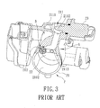
FIG. 1 , a conventional throttle valve device is adapted for use in a vehicle (not shown). The throttle valve device comprises athrottle valve 2 and asensor 3. Referring toFIGS. 2 and3 , thethrottle valve 2 includes athrottle body 21, anintake valve 22, and abypass valve 23. Thethrottle body 21 includes anintake passage 210, abypass passage 211 in fluid communication with theintake passage 210, and amounting hole 212. Theintake valve 22 is mounted rotatably in theintake passage 210 and divides theintake passage 210 into anupstreamportion 2101 and adownstreamportion 2102. Thebypass valve 23 divides thebypass passage 211 into anupstream section 2111 and adownstream section 2112. Thedownstream section 2112 has adownstream end 2113 that intersects thedownstream portion 2102 of theintake passage 210 at a first position (A) . Themounting hole 212 intersects thedownstream portion 2102 of theintake passage 210 at a second position (B). The first position (A) is spaced apart from the second position (B) . Themounting hole 212 is spaced apart from thebypass passage 211. Thesensor 3 is mounted in themounting hole 212, and has asensing portion 31 extending into thedownstream portion 2102 of theintake passage 210 and spaced apart from thedownstream section 2112 of thebypass passage 211. - When the vehicle is in an idle speed mode, the
intake valve 22 is closed and thebypass valve 23 disposed in thebypass passage 211 is opened, such that theupstream section 2111 is in fluid communication with thedownstream section 2112. Hence, intake air flows successively into theupstream portion 2101 of theintake passage 210, theupstream section 2111 and thedownstream section 2112 of thebypass passage 211, and thedownstream portion 2102 of the intake passage 210 (indicated by an arrow shown inFIG. 2 ). - An electronic control unit (ECU) (not shown) receives a temperature signal from the
sensor 3 to control the amount of the intake air that enters an engine (not shown). However, since thesensing portion 31 of thesensor 3 is disposed at a position spaced apart from thedownstream section 2112 of thebypass passage 211 for detecting the temperature of the intake air, the temperature detected by thesensing portion 31 is not actual intake air temperature in thedownstream portion 2102 of theintake passage 21. As a consequence, the ECU cannot control the amount of the intake air effectively to conform with a desired air/fuel ratio, thus resulting in inefficient fuel consumption and air pollution. - Therefore, the object of the present invention is to provide a throttle valve body that can detect actual temperature of intake air.
- According to the present invention, there is provided a throttle valve body comprising a main body and a main valve. The main body includes an intake passage, a bypass passage, and a mounting hole. The main valve is disposed in the intake passage to divide the intake passage into an upstream portion and a downstream portion. The bypass passage has an upstream section that is in fluid communication with the upstream portion of the intake passage, a downstream section that extends along a first axis, and a downstream end that is in fluid communication with the downstream portion of the intake passage. The mounting hole extends along a second axis intersecting the first axis.
- Other features and advantages of the present invention will become apparent in the following detailed description of the preferred embodiments with reference to the accompanying drawings, of which:
-
FIG. 1 is a perspective view showing a conventional throttle valve device; -
FIG. 2 is a schematic sectional view of the conventional throttle valve device; -
FIG. 3 is a partly sectional view of the conventional throttle valve device, illustrating a bypass passage and a mounting hole; -
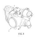
FIG. 4 is a perspective view of a first preferred embodiment of a throttle valve device according to the present invention; -
FIG. 5 is a schematic sectional view of the first preferred embodiment; -
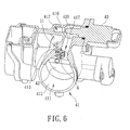
FIG. 6 is a partly sectional perspective view of the first preferred embodiment, illustrating a bypass passage and a mounting hole of the throttle valve device; and -
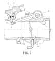
FIG. 7 is a schematic sectional view of a second preferred embodiment of a throttle valve device according to the present invention. - Before the present invention is described in greater detail, it should be noted that like elements are denoted by the same reference numerals throughout the disclosure.
- Referring to
FIG. 4 , a throttle valve device of a first preferred embodiment of the present invention comprises a throttle valve body 4 and asensor 5. - Referring to
FIG. 5 , the throttle valve body 4 includes amain body 41 and amain valve 42. Themain body 41 has anintake passage 411, abypass passage 412, a mountinghole 413, and aprotrusion 418 formed on an outer surface thereof. Themain valve 42 is disposed in theintake passage 411 to divide theintake passage 411 into anupstream portion 414 and adownstream portion 415. Thebypass passage 412 has anupstream section 416 in fluid communication with theupstream portion 414 of theintake passage 411, adownstream section 417 extending along a first axis (X), and adownstream end 419 in fluid communication with thedownstream portion 415 of theintake passage 411. - The mounting
hole 413 extends along a second axis (Y) intersecting the first axis (X), is formed in theprotrusion 418, and is in fluid communication with theintake passage 411. The first axis (X) and the second axis (Y) intersect at anintersection point 6 that is located in thedownstream section 417 of thebypass passage 412 and adjacent to thedownstream end 419. Thesensor 5 is mounted in the mountinghole 413 and has asensing portion 51 disposed adjacent to theintersection point 6. In this preferred embodiment, the first axis (X) is substantially perpendicular to the second axis (Y). - Further referring to
FIG. 6 , the throttle valve body 4 further includes a bypass valve 43 (not shown inFIG. 5 ) having abypass lever 431. When thebypass passage 412 is closed, thebypass lever 431 of thebypass valve 43 interrupts fluid communication between theupstream section 416 and thedownstream section 417 of thebypass passage 412. - The throttle valve device of the present invention is adapted for use in a vehicle. When the vehicle is in an idle speed mode, the
main valve 42 is closed and thebypass valve 43 is opened, such that theupstream section 416 is in fluid communication with thedownstream section 417. Hence, intake air flows successively into theupstream portion 414 of theintake passage 411, theupstream section 416 and thedownstream section 417 of thebypass passage 412, and thedownstream portion 415 of the intake passage 411 (indicated by an arrow shown inFIG. 5 ). Therefore, the sensingportion 51 of thesensor 5 is able to detect the temperature of the intake air, and to transmit a temperature signal to an electronic control unit (ECU) (not shown). The ECU controls the amount of intake air that enters an engine (not shown) to conform with a desired air/fuel ratio. - Since the
sensing portion 51 is mounted in the mountinghole 413 and is disposed adjacent to theintersection point 6,it can detect the temperature of the intake air in thedownstream section 417 of thebypass passage 412, i.e., the sensingportion 51 can detect effectively actual intake air temperature. As a result, the accuracy of the ECU of the vehicle that controls the amount of the intake air entering the engine cylinder is increased as compared to that of the conventional throttle body 21 (seeFIG. 3 ). - Referring to
FIG. 7 , a second preferred embodiment of the throttle valve device according to the present invention has a structure similar to that of the first embodiment. The main difference between the second embodiment and the first embodiment resides in the following. In the second preferred embodiment, the first axis (X) and the second axis (Y) intersect at anintersection point 6 that is located in thedownstream portion 415 of theintake passage 411. The sensingportion 51 of thesensor 5 is disposed adjacent to theintersection point 6. The second preferred embodiment has the same advantages as those of the first preferred embodiment. - To sum up, since the
sensing portion 51 of thesensor 5 is adjacent to theintersection point 6 where the first axis (X) and the second axis (Y) intersect, the sensingportion 51 can accurately detect the temperature of the intake air, and transmit the temperature signal to the ECU, to thereby control the amount of the intake air entering the engine so as to conform with the desired air/fuel ratio. As a result, inefficient fuel consumption and air pollution are minimized.
Claims (10)
- A throttle valve body (4) comprising:a main body (41) includingan intake passage (411) having an upstream portion (414) and a downstream portion (415),a bypass passage (412) having an upstream section (416) in fluid communication with said upstream portion (414) of said intake passage (411), a downstream section (417) extending along a first axis (X), and a downstream end (419) in fluid communication with said downstream portion (415) of said intake passage (411), anda mounting hole (413) extending along a second axis (Y); anda main valve (42) disposed in said intake passage (411) to divide said intake passage (411) into said upstream portion (414) and said downstream portion (415) ;Characterized by said first and second axes (X, Y) intersecting each other.
- The throttle valve body (4) as claimed in Claim 1,
characterized in that the first axis (X) and the second axis (Y) intersect at an intersection point (6) that is located in said downstream section (417) of said bypass passage (412) and adjacent to said downstream end (419). - The throttle valve body (4) as claimed in Claim 1,
characterized in that the first axis (X) and the second axis (Y) intersect at an intersection point (6) that is located in said downstream portion (415) of said intake passage (411). - The throttle valve body (4) as claimed in Claim 1,
characterized in that the first axis (X) is substantially perpendicular to the second axis (Y). - The throttle valve body (4) as claimed in Claim 4, further characterized in that said main body (41) further includes a protrusion (418) formed on an outer surface thereof, said mounting hole (413) being formed in said protrusion (418) and being in fluid communication with said intake passage (411).
- A throttle valve device comprising:a main body (41) includingan intake passage (411) having an upstream portion (414) and a downstream portion (415),a bypass passage (412) having an upstream section (416) in fluid communication with said upstream portion (414) of said intake passage (411), a downstream section (417) extending along a first axis (X), and a downstream end (419) in fluid communication with said downstream portion (415) of said intake passage (411), anda mounting hole (413) extending along a second axis (Y);a main valve (42) disposed in said intake passage (411) to divide said intake passage (411) into said upstream portion (414) and said downstream portion (415); anda sensor (5) mounted in said mounting hole (413);Characterized by said first and second axes (X, Y) intersecting each other.
- The throttle valve device as claimed in Claim 6,
characterized in that the first axis (X) and the second axis (Y) intersect at an intersection point (6) that is located in said downstream section (417) of said bypass passage (412) and adjacent to said downstream end (419), said sensor (5) having a sensing portion (51) disposed adjacent to said intersection point (6). - The throttle valve device as claimed in Claim 6,
characterized in that the first axis (X) and the second axis (Y) intersect at an intersection point (6) that is located in said downstream portion (415) of said intake passage (411), said sensor (5) having a sensing portion (51) disposed adjacent to said intersection point (6). - The throttle valve device as claimed in Claim 6,
characterized in that the first axis (X) is substantially perpendicular to the second axis (Y). - The throttle valve device as claimed in Claim 9, further characterized in that said main body (41) further includes a protrusion (418) formed on an outer surface thereof, said mounting hole (413) being formed in said protrusion (418) and being in fluid communication with said intake passage (411).
Applications Claiming Priority (1)
| Application Number | Priority Date | Filing Date | Title |
|---|---|---|---|
| TW097150962A TW201024528A (en) | 2008-12-26 | 2008-12-26 | Throttle valve and device thereof |
Publications (3)
| Publication Number | Publication Date |
|---|---|
| EP2202397A2 true EP2202397A2 (en) | 2010-06-30 |
| EP2202397A3 EP2202397A3 (en) | 2013-04-03 |
| EP2202397B1 EP2202397B1 (en) | 2016-03-16 |
Family
ID=42041776
Family Applications (1)
| Application Number | Title | Priority Date | Filing Date |
|---|---|---|---|
| EP09179672.2A Not-in-force EP2202397B1 (en) | 2008-12-26 | 2009-12-17 | Throttle valve body and throttle valve device having the same |
Country Status (3)
| Country | Link |
|---|---|
| US (1) | US20100162995A1 (en) |
| EP (1) | EP2202397B1 (en) |
| TW (1) | TW201024528A (en) |
Cited By (1)
| Publication number | Priority date | Publication date | Assignee | Title |
|---|---|---|---|---|
| WO2018048740A1 (en) * | 2016-09-09 | 2018-03-15 | Walbro Llc | Throttle body with fluid flow control |
Families Citing this family (1)
| Publication number | Priority date | Publication date | Assignee | Title |
|---|---|---|---|---|
| WO2018163912A1 (en) * | 2017-03-10 | 2018-09-13 | 本田技研工業株式会社 | Air intake structure for internal combustion engine |
Citations (3)
| Publication number | Priority date | Publication date | Assignee | Title |
|---|---|---|---|---|
| GB2052796A (en) | 1979-05-09 | 1981-01-28 | Hitachi Ltd | Automatic control of air/fuel ratio in i c engines |
| JPH09166033A (en) | 1995-11-02 | 1997-06-24 | Nippon Carbureter Co Ltd | Intake device for engine |
| US20060065238A1 (en) | 2004-09-01 | 2006-03-30 | Keihin Corporation | Idle speed control apparatus in throttle body for single cylinder |
Family Cites Families (9)
| Publication number | Priority date | Publication date | Assignee | Title |
|---|---|---|---|---|
| US5722367A (en) * | 1995-10-10 | 1998-03-03 | Walbro Corporation | Engine idle speed air control |
| US6041754A (en) * | 1997-04-14 | 2000-03-28 | Nippon Soken, Inc. | Idle intake control device |
| AU756938B1 (en) * | 2002-04-04 | 2003-01-30 | Hyundai Motor Company | Engine idle speed control device |
| JP2004211612A (en) * | 2003-01-06 | 2004-07-29 | Keihin Corp | Idle speed control device for multi-cylinder throttle body |
| JP4154411B2 (en) * | 2005-08-29 | 2008-09-24 | 株式会社ケーヒン | Engine intake system |
| JP4690949B2 (en) * | 2006-06-13 | 2011-06-01 | 株式会社ケーヒン | Engine intake system |
| US7353812B1 (en) * | 2007-03-14 | 2008-04-08 | Ford Global Technologies, Llc | Vehicle engine with integral vacuum generator |
| JP5046736B2 (en) * | 2007-05-09 | 2012-10-10 | 川崎重工業株式会社 | Jet propulsion boat |
| JP4864813B2 (en) * | 2007-05-25 | 2012-02-01 | 川崎重工業株式会社 | Jet propulsion boat |
-
2008
- 2008-12-26 TW TW097150962A patent/TW201024528A/en not_active IP Right Cessation
-
2009
- 2009-12-17 EP EP09179672.2A patent/EP2202397B1/en not_active Not-in-force
- 2009-12-22 US US12/644,755 patent/US20100162995A1/en not_active Abandoned
Patent Citations (3)
| Publication number | Priority date | Publication date | Assignee | Title |
|---|---|---|---|---|
| GB2052796A (en) | 1979-05-09 | 1981-01-28 | Hitachi Ltd | Automatic control of air/fuel ratio in i c engines |
| JPH09166033A (en) | 1995-11-02 | 1997-06-24 | Nippon Carbureter Co Ltd | Intake device for engine |
| US20060065238A1 (en) | 2004-09-01 | 2006-03-30 | Keihin Corporation | Idle speed control apparatus in throttle body for single cylinder |
Cited By (3)
| Publication number | Priority date | Publication date | Assignee | Title |
|---|---|---|---|---|
| WO2018048740A1 (en) * | 2016-09-09 | 2018-03-15 | Walbro Llc | Throttle body with fluid flow control |
| US11268455B2 (en) | 2016-09-09 | 2022-03-08 | Walbro Llc | Throttle body with fluid flow control |
| US11781493B2 (en) | 2016-09-09 | 2023-10-10 | Walbro Llc | Throttle body with fluid flow control |
Also Published As
| Publication number | Publication date |
|---|---|
| TWI342360B (en) | 2011-05-21 |
| TW201024528A (en) | 2010-07-01 |
| EP2202397B1 (en) | 2016-03-16 |
| US20100162995A1 (en) | 2010-07-01 |
| EP2202397A3 (en) | 2013-04-03 |
Similar Documents
| Publication | Publication Date | Title |
|---|---|---|
| US7946158B2 (en) | Air flow measuring device | |
| EP2060879A1 (en) | Air flow measuring instrument | |
| TWI319044B (en) | ||
| US20100031737A1 (en) | Mass air flow measurement device | |
| US6810725B2 (en) | Exhaust gas recirculation measurement device | |
| JP4951006B2 (en) | Exhaust turbocharger for internal combustion engines | |
| US20070234716A1 (en) | Vehicular ejector system and controller and control method for vehicular ejector system | |
| CN105189987B (en) | The inlet duct of engine for motor bicycle | |
| EP2202397A2 (en) | Throttle valve body and throttle valve device having the same | |
| US7140344B2 (en) | Air cleaner | |
| US8955493B2 (en) | Throttle valve body and throttle valve device having the same | |
| US6920864B1 (en) | Throttle body | |
| US20090308147A1 (en) | Air Flow Measuring Device | |
| JP5542614B2 (en) | Flow measuring device | |
| JPH1047120A (en) | Deposit detection device | |
| EP1917430A1 (en) | Control system and control method for internal combustion engine | |
| JP4173847B2 (en) | Intake device for internal combustion engine | |
| JP4173833B2 (en) | Intake device for internal combustion engine | |
| JP4532373B2 (en) | Engine fuel injection control method and fuel injection control device | |
| JPH08278179A (en) | Heat resistance type air flow rate measuring device | |
| JP4245163B2 (en) | Intake device for internal combustion engine | |
| JPH029082Y2 (en) | ||
| CN1111254C (en) | Device for monitoring the function of an exhaust gas recirculation valve of an internal combustion engine | |
| JPH109921A (en) | Air flow measurement device | |
| JP2007321661A (en) | Idle rotation control device for internal combustion engine |
Legal Events
| Date | Code | Title | Description |
|---|---|---|---|
| PUAI | Public reference made under article 153(3) epc to a published international application that has entered the european phase |
Free format text: ORIGINAL CODE: 0009012 |
|
| AK | Designated contracting states |
Kind code of ref document: A2 Designated state(s): AT BE BG CH CY CZ DE DK EE ES FI FR GB GR HR HU IE IS IT LI LT LU LV MC MK MT NL NO PL PT RO SE SI SK SM TR |
|
| PUAL | Search report despatched |
Free format text: ORIGINAL CODE: 0009013 |
|
| AK | Designated contracting states |
Kind code of ref document: A3 Designated state(s): AT BE BG CH CY CZ DE DK EE ES FI FR GB GR HR HU IE IS IT LI LT LU LV MC MK MT NL NO PL PT RO SE SI SK SM TR |
|
| RIC1 | Information provided on ipc code assigned before grant |
Ipc: F02D 9/10 20060101AFI20130228BHEP |
|
| 17P | Request for examination filed |
Effective date: 20131001 |
|
| RBV | Designated contracting states (corrected) |
Designated state(s): AT BE BG CH CY CZ DE DK EE ES FI FR GB GR HR HU IE IS IT LI LT LU LV MC MK MT NL NO PL PT RO SE SI SK SM TR |
|
| 17Q | First examination report despatched |
Effective date: 20150129 |
|
| GRAP | Despatch of communication of intention to grant a patent |
Free format text: ORIGINAL CODE: EPIDOSNIGR1 |
|
| INTG | Intention to grant announced |
Effective date: 20151006 |
|
| GRAS | Grant fee paid |
Free format text: ORIGINAL CODE: EPIDOSNIGR3 |
|
| GRAA | (expected) grant |
Free format text: ORIGINAL CODE: 0009210 |
|
| AK | Designated contracting states |
Kind code of ref document: B1 Designated state(s): AT BE BG CH CY CZ DE DK EE ES FI FR GB GR HR HU IE IS IT LI LT LU LV MC MK MT NL NO PL PT RO SE SI SK SM TR |
|
| REG | Reference to a national code |
Ref country code: GB Ref legal event code: FG4D |
|
| REG | Reference to a national code |
Ref country code: CH Ref legal event code: EP |
|
| REG | Reference to a national code |
Ref country code: IE Ref legal event code: FG4D |
|
| REG | Reference to a national code |
Ref country code: AT Ref legal event code: REF Ref document number: 781468 Country of ref document: AT Kind code of ref document: T Effective date: 20160415 |
|
| REG | Reference to a national code |
Ref country code: DE Ref legal event code: R096 Ref document number: 602009036787 Country of ref document: DE |
|
| REG | Reference to a national code |
Ref country code: NL Ref legal event code: MP Effective date: 20160316 |
|
| REG | Reference to a national code |
Ref country code: LT Ref legal event code: MG4D |
|
| PG25 | Lapsed in a contracting state [announced via postgrant information from national office to epo] |
Ref country code: HR Free format text: LAPSE BECAUSE OF FAILURE TO SUBMIT A TRANSLATION OF THE DESCRIPTION OR TO PAY THE FEE WITHIN THE PRESCRIBED TIME-LIMIT Effective date: 20160316 Ref country code: NO Free format text: LAPSE BECAUSE OF FAILURE TO SUBMIT A TRANSLATION OF THE DESCRIPTION OR TO PAY THE FEE WITHIN THE PRESCRIBED TIME-LIMIT Effective date: 20160616 Ref country code: FI Free format text: LAPSE BECAUSE OF FAILURE TO SUBMIT A TRANSLATION OF THE DESCRIPTION OR TO PAY THE FEE WITHIN THE PRESCRIBED TIME-LIMIT Effective date: 20160316 Ref country code: GR Free format text: LAPSE BECAUSE OF FAILURE TO SUBMIT A TRANSLATION OF THE DESCRIPTION OR TO PAY THE FEE WITHIN THE PRESCRIBED TIME-LIMIT Effective date: 20160617 |
|
| REG | Reference to a national code |
Ref country code: AT Ref legal event code: MK05 Ref document number: 781468 Country of ref document: AT Kind code of ref document: T Effective date: 20160316 |
|
| PG25 | Lapsed in a contracting state [announced via postgrant information from national office to epo] |
Ref country code: LT Free format text: LAPSE BECAUSE OF FAILURE TO SUBMIT A TRANSLATION OF THE DESCRIPTION OR TO PAY THE FEE WITHIN THE PRESCRIBED TIME-LIMIT Effective date: 20160316 Ref country code: LV Free format text: LAPSE BECAUSE OF FAILURE TO SUBMIT A TRANSLATION OF THE DESCRIPTION OR TO PAY THE FEE WITHIN THE PRESCRIBED TIME-LIMIT Effective date: 20160316 Ref country code: SE Free format text: LAPSE BECAUSE OF FAILURE TO SUBMIT A TRANSLATION OF THE DESCRIPTION OR TO PAY THE FEE WITHIN THE PRESCRIBED TIME-LIMIT Effective date: 20160316 Ref country code: NL Free format text: LAPSE BECAUSE OF FAILURE TO SUBMIT A TRANSLATION OF THE DESCRIPTION OR TO PAY THE FEE WITHIN THE PRESCRIBED TIME-LIMIT Effective date: 20160316 |
|
| REG | Reference to a national code |
Ref country code: FR Ref legal event code: PLFP Year of fee payment: 8 |
|
| PG25 | Lapsed in a contracting state [announced via postgrant information from national office to epo] |
Ref country code: EE Free format text: LAPSE BECAUSE OF FAILURE TO SUBMIT A TRANSLATION OF THE DESCRIPTION OR TO PAY THE FEE WITHIN THE PRESCRIBED TIME-LIMIT Effective date: 20160316 Ref country code: PL Free format text: LAPSE BECAUSE OF FAILURE TO SUBMIT A TRANSLATION OF THE DESCRIPTION OR TO PAY THE FEE WITHIN THE PRESCRIBED TIME-LIMIT Effective date: 20160316 Ref country code: IS Free format text: LAPSE BECAUSE OF FAILURE TO SUBMIT A TRANSLATION OF THE DESCRIPTION OR TO PAY THE FEE WITHIN THE PRESCRIBED TIME-LIMIT Effective date: 20160716 |
|
| PG25 | Lapsed in a contracting state [announced via postgrant information from national office to epo] |
Ref country code: ES Free format text: LAPSE BECAUSE OF FAILURE TO SUBMIT A TRANSLATION OF THE DESCRIPTION OR TO PAY THE FEE WITHIN THE PRESCRIBED TIME-LIMIT Effective date: 20160316 Ref country code: PT Free format text: LAPSE BECAUSE OF FAILURE TO SUBMIT A TRANSLATION OF THE DESCRIPTION OR TO PAY THE FEE WITHIN THE PRESCRIBED TIME-LIMIT Effective date: 20160718 Ref country code: SM Free format text: LAPSE BECAUSE OF FAILURE TO SUBMIT A TRANSLATION OF THE DESCRIPTION OR TO PAY THE FEE WITHIN THE PRESCRIBED TIME-LIMIT Effective date: 20160316 Ref country code: AT Free format text: LAPSE BECAUSE OF FAILURE TO SUBMIT A TRANSLATION OF THE DESCRIPTION OR TO PAY THE FEE WITHIN THE PRESCRIBED TIME-LIMIT Effective date: 20160316 Ref country code: CZ Free format text: LAPSE BECAUSE OF FAILURE TO SUBMIT A TRANSLATION OF THE DESCRIPTION OR TO PAY THE FEE WITHIN THE PRESCRIBED TIME-LIMIT Effective date: 20160316 Ref country code: SK Free format text: LAPSE BECAUSE OF FAILURE TO SUBMIT A TRANSLATION OF THE DESCRIPTION OR TO PAY THE FEE WITHIN THE PRESCRIBED TIME-LIMIT Effective date: 20160316 Ref country code: RO Free format text: LAPSE BECAUSE OF FAILURE TO SUBMIT A TRANSLATION OF THE DESCRIPTION OR TO PAY THE FEE WITHIN THE PRESCRIBED TIME-LIMIT Effective date: 20160316 |
|
| REG | Reference to a national code |
Ref country code: DE Ref legal event code: R097 Ref document number: 602009036787 Country of ref document: DE |
|
| PG25 | Lapsed in a contracting state [announced via postgrant information from national office to epo] |
Ref country code: IT Free format text: LAPSE BECAUSE OF FAILURE TO SUBMIT A TRANSLATION OF THE DESCRIPTION OR TO PAY THE FEE WITHIN THE PRESCRIBED TIME-LIMIT Effective date: 20160316 Ref country code: BE Free format text: LAPSE BECAUSE OF FAILURE TO SUBMIT A TRANSLATION OF THE DESCRIPTION OR TO PAY THE FEE WITHIN THE PRESCRIBED TIME-LIMIT Effective date: 20160316 |
|
| PLBE | No opposition filed within time limit |
Free format text: ORIGINAL CODE: 0009261 |
|
| STAA | Information on the status of an ep patent application or granted ep patent |
Free format text: STATUS: NO OPPOSITION FILED WITHIN TIME LIMIT |
|
| PG25 | Lapsed in a contracting state [announced via postgrant information from national office to epo] |
Ref country code: DK Free format text: LAPSE BECAUSE OF FAILURE TO SUBMIT A TRANSLATION OF THE DESCRIPTION OR TO PAY THE FEE WITHIN THE PRESCRIBED TIME-LIMIT Effective date: 20160316 |
|
| 26N | No opposition filed |
Effective date: 20161219 |
|
| PG25 | Lapsed in a contracting state [announced via postgrant information from national office to epo] |
Ref country code: BG Free format text: LAPSE BECAUSE OF FAILURE TO SUBMIT A TRANSLATION OF THE DESCRIPTION OR TO PAY THE FEE WITHIN THE PRESCRIBED TIME-LIMIT Effective date: 20160616 |
|
| PG25 | Lapsed in a contracting state [announced via postgrant information from national office to epo] |
Ref country code: SI Free format text: LAPSE BECAUSE OF FAILURE TO SUBMIT A TRANSLATION OF THE DESCRIPTION OR TO PAY THE FEE WITHIN THE PRESCRIBED TIME-LIMIT Effective date: 20160316 |
|
| REG | Reference to a national code |
Ref country code: CH Ref legal event code: PL |
|
| GBPC | Gb: european patent ceased through non-payment of renewal fee |
Effective date: 20161217 |
|
| PG25 | Lapsed in a contracting state [announced via postgrant information from national office to epo] |
Ref country code: MC Free format text: LAPSE BECAUSE OF FAILURE TO SUBMIT A TRANSLATION OF THE DESCRIPTION OR TO PAY THE FEE WITHIN THE PRESCRIBED TIME-LIMIT Effective date: 20160316 |
|
| REG | Reference to a national code |
Ref country code: IE Ref legal event code: MM4A |
|
| PG25 | Lapsed in a contracting state [announced via postgrant information from national office to epo] |
Ref country code: LU Free format text: LAPSE BECAUSE OF NON-PAYMENT OF DUE FEES Effective date: 20161217 Ref country code: CH Free format text: LAPSE BECAUSE OF NON-PAYMENT OF DUE FEES Effective date: 20161231 Ref country code: LI Free format text: LAPSE BECAUSE OF NON-PAYMENT OF DUE FEES Effective date: 20161231 |
|
| REG | Reference to a national code |
Ref country code: FR Ref legal event code: PLFP Year of fee payment: 9 |
|
| PG25 | Lapsed in a contracting state [announced via postgrant information from national office to epo] |
Ref country code: GB Free format text: LAPSE BECAUSE OF NON-PAYMENT OF DUE FEES Effective date: 20161217 Ref country code: IE Free format text: LAPSE BECAUSE OF NON-PAYMENT OF DUE FEES Effective date: 20161217 |
|
| PG25 | Lapsed in a contracting state [announced via postgrant information from national office to epo] |
Ref country code: HU Free format text: LAPSE BECAUSE OF FAILURE TO SUBMIT A TRANSLATION OF THE DESCRIPTION OR TO PAY THE FEE WITHIN THE PRESCRIBED TIME-LIMIT; INVALID AB INITIO Effective date: 20091217 Ref country code: CY Free format text: LAPSE BECAUSE OF FAILURE TO SUBMIT A TRANSLATION OF THE DESCRIPTION OR TO PAY THE FEE WITHIN THE PRESCRIBED TIME-LIMIT Effective date: 20160316 |
|
| PG25 | Lapsed in a contracting state [announced via postgrant information from national office to epo] |
Ref country code: MK Free format text: LAPSE BECAUSE OF FAILURE TO SUBMIT A TRANSLATION OF THE DESCRIPTION OR TO PAY THE FEE WITHIN THE PRESCRIBED TIME-LIMIT Effective date: 20160316 Ref country code: TR Free format text: LAPSE BECAUSE OF FAILURE TO SUBMIT A TRANSLATION OF THE DESCRIPTION OR TO PAY THE FEE WITHIN THE PRESCRIBED TIME-LIMIT Effective date: 20160316 |
|
| REG | Reference to a national code |
Ref country code: FR Ref legal event code: PLFP Year of fee payment: 10 |
|
| PG25 | Lapsed in a contracting state [announced via postgrant information from national office to epo] |
Ref country code: MT Free format text: LAPSE BECAUSE OF NON-PAYMENT OF DUE FEES Effective date: 20161217 |
|
| PGFP | Annual fee paid to national office [announced via postgrant information from national office to epo] |
Ref country code: FR Payment date: 20200409 Year of fee payment: 12 |
|
| PGFP | Annual fee paid to national office [announced via postgrant information from national office to epo] |
Ref country code: DE Payment date: 20200417 Year of fee payment: 12 |
|
| REG | Reference to a national code |
Ref country code: DE Ref legal event code: R119 Ref document number: 602009036787 Country of ref document: DE |
|
| PG25 | Lapsed in a contracting state [announced via postgrant information from national office to epo] |
Ref country code: DE Free format text: LAPSE BECAUSE OF NON-PAYMENT OF DUE FEES Effective date: 20220701 |
|
| PG25 | Lapsed in a contracting state [announced via postgrant information from national office to epo] |
Ref country code: FR Free format text: LAPSE BECAUSE OF NON-PAYMENT OF DUE FEES Effective date: 20211231 |