EP2202391A1 - Construction machine - Google Patents
Construction machine Download PDFInfo
- Publication number
- EP2202391A1 EP2202391A1 EP08841353A EP08841353A EP2202391A1 EP 2202391 A1 EP2202391 A1 EP 2202391A1 EP 08841353 A EP08841353 A EP 08841353A EP 08841353 A EP08841353 A EP 08841353A EP 2202391 A1 EP2202391 A1 EP 2202391A1
- Authority
- EP
- European Patent Office
- Prior art keywords
- exhaust gas
- disposed
- treatment
- opening
- top plate
- Prior art date
- Legal status (The legal status is an assumption and is not a legal conclusion. Google has not performed a legal analysis and makes no representation as to the accuracy of the status listed.)
- Granted
Links
Images





Classifications
-
- E—FIXED CONSTRUCTIONS
- E02—HYDRAULIC ENGINEERING; FOUNDATIONS; SOIL SHIFTING
- E02F—DREDGING; SOIL-SHIFTING
- E02F9/00—Component parts of dredgers or soil-shifting machines, not restricted to one of the kinds covered by groups E02F3/00 - E02F7/00
- E02F9/08—Superstructures; Supports for superstructures
- E02F9/0858—Arrangement of component parts installed on superstructures not otherwise provided for, e.g. electric components, fenders, air-conditioning units
- E02F9/0891—Lids or bonnets or doors or details thereof
-
- B—PERFORMING OPERATIONS; TRANSPORTING
- B60—VEHICLES IN GENERAL
- B60K—ARRANGEMENT OR MOUNTING OF PROPULSION UNITS OR OF TRANSMISSIONS IN VEHICLES; ARRANGEMENT OR MOUNTING OF PLURAL DIVERSE PRIME-MOVERS IN VEHICLES; AUXILIARY DRIVES FOR VEHICLES; INSTRUMENTATION OR DASHBOARDS FOR VEHICLES; ARRANGEMENTS IN CONNECTION WITH COOLING, AIR INTAKE, GAS EXHAUST OR FUEL SUPPLY OF PROPULSION UNITS IN VEHICLES
- B60K13/00—Arrangement in connection with combustion air intake or gas exhaust of propulsion units
- B60K13/04—Arrangement in connection with combustion air intake or gas exhaust of propulsion units concerning exhaust
-
- E—FIXED CONSTRUCTIONS
- E02—HYDRAULIC ENGINEERING; FOUNDATIONS; SOIL SHIFTING
- E02F—DREDGING; SOIL-SHIFTING
- E02F9/00—Component parts of dredgers or soil-shifting machines, not restricted to one of the kinds covered by groups E02F3/00 - E02F7/00
-
- E—FIXED CONSTRUCTIONS
- E02—HYDRAULIC ENGINEERING; FOUNDATIONS; SOIL SHIFTING
- E02F—DREDGING; SOIL-SHIFTING
- E02F9/00—Component parts of dredgers or soil-shifting machines, not restricted to one of the kinds covered by groups E02F3/00 - E02F7/00
- E02F9/08—Superstructures; Supports for superstructures
- E02F9/0858—Arrangement of component parts installed on superstructures not otherwise provided for, e.g. electric components, fenders, air-conditioning units
- E02F9/0866—Engine compartment, e.g. heat exchangers, exhaust filters, cooling devices, silencers, mufflers, position of hydraulic pumps in the engine compartment
-
- F—MECHANICAL ENGINEERING; LIGHTING; HEATING; WEAPONS; BLASTING
- F01—MACHINES OR ENGINES IN GENERAL; ENGINE PLANTS IN GENERAL; STEAM ENGINES
- F01N—GAS-FLOW SILENCERS OR EXHAUST APPARATUS FOR MACHINES OR ENGINES IN GENERAL; GAS-FLOW SILENCERS OR EXHAUST APPARATUS FOR INTERNAL-COMBUSTION ENGINES
- F01N13/00—Exhaust or silencing apparatus characterised by constructional features
- F01N13/08—Other arrangements or adaptations of exhaust conduits
-
- F—MECHANICAL ENGINEERING; LIGHTING; HEATING; WEAPONS; BLASTING
- F01—MACHINES OR ENGINES IN GENERAL; ENGINE PLANTS IN GENERAL; STEAM ENGINES
- F01N—GAS-FLOW SILENCERS OR EXHAUST APPARATUS FOR MACHINES OR ENGINES IN GENERAL; GAS-FLOW SILENCERS OR EXHAUST APPARATUS FOR INTERNAL-COMBUSTION ENGINES
- F01N3/00—Exhaust or silencing apparatus having means for purifying, rendering innocuous, or otherwise treating exhaust
- F01N3/02—Exhaust or silencing apparatus having means for purifying, rendering innocuous, or otherwise treating exhaust for cooling, or for removing solid constituents of, exhaust
- F01N3/021—Exhaust or silencing apparatus having means for purifying, rendering innocuous, or otherwise treating exhaust for cooling, or for removing solid constituents of, exhaust by means of filters
- F01N3/033—Exhaust or silencing apparatus having means for purifying, rendering innocuous, or otherwise treating exhaust for cooling, or for removing solid constituents of, exhaust by means of filters in combination with other devices
- F01N3/035—Exhaust or silencing apparatus having means for purifying, rendering innocuous, or otherwise treating exhaust for cooling, or for removing solid constituents of, exhaust by means of filters in combination with other devices with catalytic reactors
-
- B—PERFORMING OPERATIONS; TRANSPORTING
- B01—PHYSICAL OR CHEMICAL PROCESSES OR APPARATUS IN GENERAL
- B01D—SEPARATION
- B01D2251/00—Reactants
- B01D2251/20—Reductants
- B01D2251/206—Ammonium compounds
- B01D2251/2067—Urea
-
- B—PERFORMING OPERATIONS; TRANSPORTING
- B01—PHYSICAL OR CHEMICAL PROCESSES OR APPARATUS IN GENERAL
- B01D—SEPARATION
- B01D2257/00—Components to be removed
- B01D2257/40—Nitrogen compounds
- B01D2257/402—Dinitrogen oxide
-
- B—PERFORMING OPERATIONS; TRANSPORTING
- B01—PHYSICAL OR CHEMICAL PROCESSES OR APPARATUS IN GENERAL
- B01D—SEPARATION
- B01D2257/00—Components to be removed
- B01D2257/40—Nitrogen compounds
- B01D2257/404—Nitrogen oxides other than dinitrogen oxide
-
- B—PERFORMING OPERATIONS; TRANSPORTING
- B01—PHYSICAL OR CHEMICAL PROCESSES OR APPARATUS IN GENERAL
- B01D—SEPARATION
- B01D2257/00—Components to be removed
- B01D2257/70—Organic compounds not provided for in groups B01D2257/00 - B01D2257/602
- B01D2257/702—Hydrocarbons
-
- B—PERFORMING OPERATIONS; TRANSPORTING
- B01—PHYSICAL OR CHEMICAL PROCESSES OR APPARATUS IN GENERAL
- B01D—SEPARATION
- B01D2258/00—Sources of waste gases
- B01D2258/01—Engine exhaust gases
- B01D2258/012—Diesel engines and lean burn gasoline engines
-
- B—PERFORMING OPERATIONS; TRANSPORTING
- B60—VEHICLES IN GENERAL
- B60Y—INDEXING SCHEME RELATING TO ASPECTS CROSS-CUTTING VEHICLE TECHNOLOGY
- B60Y2200/00—Type of vehicle
- B60Y2200/40—Special vehicles
- B60Y2200/41—Construction vehicles, e.g. graders, excavators
- B60Y2200/412—Excavators
-
- F—MECHANICAL ENGINEERING; LIGHTING; HEATING; WEAPONS; BLASTING
- F01—MACHINES OR ENGINES IN GENERAL; ENGINE PLANTS IN GENERAL; STEAM ENGINES
- F01N—GAS-FLOW SILENCERS OR EXHAUST APPARATUS FOR MACHINES OR ENGINES IN GENERAL; GAS-FLOW SILENCERS OR EXHAUST APPARATUS FOR INTERNAL-COMBUSTION ENGINES
- F01N2340/00—Dimensional characteristics of the exhaust system, e.g. length, diameter or volume of the exhaust apparatus; Spatial arrangements of exhaust apparatuses
- F01N2340/04—Arrangement of the exhaust system relative to a vehicle or parts thereof
-
- F—MECHANICAL ENGINEERING; LIGHTING; HEATING; WEAPONS; BLASTING
- F01—MACHINES OR ENGINES IN GENERAL; ENGINE PLANTS IN GENERAL; STEAM ENGINES
- F01N—GAS-FLOW SILENCERS OR EXHAUST APPARATUS FOR MACHINES OR ENGINES IN GENERAL; GAS-FLOW SILENCERS OR EXHAUST APPARATUS FOR INTERNAL-COMBUSTION ENGINES
- F01N2590/00—Exhaust or silencing apparatus adapted to particular use, e.g. for military applications, airplanes, submarines
- F01N2590/08—Exhaust or silencing apparatus adapted to particular use, e.g. for military applications, airplanes, submarines for heavy duty applications, e.g. trucks, buses, tractors, locomotives
-
- Y—GENERAL TAGGING OF NEW TECHNOLOGICAL DEVELOPMENTS; GENERAL TAGGING OF CROSS-SECTIONAL TECHNOLOGIES SPANNING OVER SEVERAL SECTIONS OF THE IPC; TECHNICAL SUBJECTS COVERED BY FORMER USPC CROSS-REFERENCE ART COLLECTIONS [XRACs] AND DIGESTS
- Y02—TECHNOLOGIES OR APPLICATIONS FOR MITIGATION OR ADAPTATION AGAINST CLIMATE CHANGE
- Y02C—CAPTURE, STORAGE, SEQUESTRATION OR DISPOSAL OF GREENHOUSE GASES [GHG]
- Y02C20/00—Capture or disposal of greenhouse gases
- Y02C20/10—Capture or disposal of greenhouse gases of nitrous oxide (N2O)
Definitions
- the present invention relates to a construction machine provided with an exhaust gas after-treatment device for purifying exhaust gas from an engine.
- a construction machine provided with a base frame which supports a working attachment so as to be raised and lowered, an engine installed on the base frame, and a guard panel for covering over the base frame.
- an exhaust gas after-treatment device for purifying exhaust gas from an engine be installed on a base frame.
- the aforesaid exhaust gas after-treatment device has a DPF (Diesel Particulate Filter) for decreasing the amount of dust such as soot and mist contained in the engine exhaust gas and also has a reduction catalyst for decreasing the amount of NOx contained in the exhaust gas (see, for example, Patent Documents 1 and 2).
- DPF Diesel Particulate Filter
- the engine and related peripheral devices e.g., hydraulic systems
- the engine and related peripheral devices are disposed in a planarly massed layout on the base frame, it is difficult to newly ensure on the base frame a space as a planar space for disposing the exhaust gas after-treatment device.
- One countermeasure is to ensure a new space over the base frame.
- the exhaust gas after-treatment device over the engine and a peripheral device thereof, not only the construction machine itself becomes larger in height, but also there results the problem that the visual field from the operator becomes narrow.
- the present invention has been accomplished in view of the above-mentioned problem and it is an object of the invention to provide a construction machine which permits an exhaust gas after-treatment device to be disposed while avoiding an increase of height and hence avoiding narrowing of the operator's visual field.
- the present invention provides a construction machine having a working attachment, the construction machine including: a base frame for supporting the working attachment so as to be raised and lowered; an engine installed on the base frame; an exhaust gas after-treatment device able to purify exhaust gas from the engine while the exhaust gas flows therethrough; and a guard panel installed over the base frame so as to cover the engine and the exhaust gas after-treatment device, wherein the exhaust gas after-treatment device includes a first treatment section having a filter able to collect dust contained in the exhaust gas from the engine and a second treatment section having a catalyst for decomposing nitrogen oxides contained in the exhaust gas treated by the first treatment section, the guard panel includes a top plate, the top plate being disposed substantially in parallel with the base frame and having an opening in a portion thereof corresponding to the engine, and a bonnet formed so as to project upwards from the top plate and cover the opening, one of the first and second treatment sections is disposed lower than the top plate, and at least a part of the other treatment section is disposed higher
- an exhaust gas after-treatment device can be disposed while suppressing an increase of height and hence suppressing narrowing of the operator's visual field.
- Fig. 1 is a perspective view showing an upper rotating body of a hydraulic excavator according to an embodiment of the present invention.
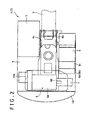
- Fig. 2 is a plan view of the upper rotating body of Fig. 1 with both a guard panel and exhaust gas after-treatment device omitted.
- Fig. 3 is a perspective view showing a state in which an exhaust gas after-treatment device is disposed on the upper rotating body of Fig. 2 .
- a hydraulic excavator 1 is provided with a crawler type lower traveling body (not shown), an upper rotating body 2 mounted rotatably on the lower traveling body, and a working attachment 3 (see Fig. 2 ) supported so as to be raised and lowered with respect to the upper rotating body 2.
- the upper rotating body 2 is provided with a base frame 4 installed on the lower traveling body, a guard panel 12 which covers over the base frame 4, as well as a cabin 5, an engine 6, a hydraulic pump 7, a working oil tank 8, a fuel tank 9, a counterweight 10, and an exhaust gas after-treatment device 11 (see Fig. 3 ), which are all installed on the base frame 4.
- a base frame 4 installed on the lower traveling body
- a guard panel 12 which covers over the base frame 4
- a cabin 5 an engine 6, a hydraulic pump 7, a working oil tank 8, a fuel tank 9, a counterweight 10, and an exhaust gas after-treatment device 11 (see Fig. 3 ), which are all installed on the base frame 4.
- the direction from front to rear and the direction from right to left as seen from an operator sitting on an operator's seat (not shown) within the cabin 5 are longitudinal and transverse directions, respectively, of the upper rotating body 2.
- a pair of left and right vertical plates 4a and 4b extending in the longitudinal direction are erected on the base frame 4 at a nearly central position in the transverse direction.
- the working attachment 3 is supported between front portions of the vertical plates 4a and 4b.
- the cabin 5 is installed at a left front position of the left vertical plate 4a.
- the engine 6 is installed on the vertical plates 4a and 4b at a rear portion of the base frame 4 so that its longitudinal direction faces in the transverse direction.
- the engine 6 includes an engine body 6a and an output shaft 6b projecting rightwards from a right end face of the engine body 6a. Aright end portion of the engine body 6a is disposed substantially above the right vertical plate 4b.
- the hydraulic pump 7 is connected transversely to the output shaft 6b through a coupling (not shown) or the like so as to become capable of being operated with the power of the engine 6. As a result, the hydraulic pump 7 is disposed in an area from above the right vertical plate 4b to the right side of the same plate (see Fig. 2 ).
- the working oil tank 8 and the fuel tank 9 are disposed longitudinally in a line at the right-hand position of the right vertical plate 4b. That is, the fuel tank 9 is disposed in the front and the working oil tank 8 is disposed in the rear. As a result, the working oil tank 8 is disposed adjacently to and in front of the hydraulic pump 7.
- the working oil tank 8 includes, as integral components, a large height portion 8c having a height almost equal to the height of the counterweight 10, and a small height portion 8b formed behind the large height portion 8c and having an upper surface 8a, the upper surface 8a having a height H5 almost equal to or lower than the height H4 (see Fig. 4 ) of the hydraulic pump 7.
- the counterweight 10 is provided along a rear edge portion of the base frame 4. That is, the counterweight 10 confronts the working oil tank 8 longitudinally with the hydraulic pump 7 therebetween.
- the exhaust gas after-treatment device 11, which is for purifying exhaust gas from the engine 6, is installed between the counterweight 10 and the working oil tank 8 and over the hydraulic pump 7. As to the structure of the exhaust gas after-treatment device 11, it will be described later.
- the guard panel 12 is installed over the base panel 4 so as to cover the engine 6, hydraulic pump 7, working oil tank 8, fuel tank 9 and exhaust gas after-treatment device 11. More specifically, the guard panel 12 includes a top plate 14 disposed substantially in parallel with the base frame 4, a pair of side plates 15 provided at right and left edge portions of the top plate 14 (only the right one is shown in Fig. 1 ), and a bonnet 16 provided so as to project upwards from the top plate 14.
- the top plate 14 is installed longitudinally within from the counterweight 10 to the cabin 5 so as to cover the engine 6, hydraulic pump 7, working oil tank 8, fuel tank 9 and exhaust gas after-treatment device 11.
- the top plate 14 is installed at a height position almost equal to the counterweight 10.
- the top plate 14 is formed with an opening 14a (see Fig. 2 ) opening through the plate at a position corresponding to the engine 6. Maintenance of the engine 6 (particularly of the engine body 6a) is performed through the opening 14a.
- the bonnet 16 is attached to an upper surface of the top plate 14 through a hinge (not shown) so as to permit opening or closing of the opening 14a.
- the bonnet 16 is formed in the shape of a vessel which swells upwards in its closed state, so that the inner space of the guard panel 12 is expanded upwards by a volume corresponding to the inner space of the bonnet 16.
- Height positions to be referred to below are the height positions from the base frame 4.
- the height H1 of the engine body 6a is almost equal to or a little higher than the height H2 of the top plate 14 and is lower than the height H3 of the bonnet 16.
- the height H4 of the hydraulic pump 7 is lower than each of the heights H1 to H3.
- Between the hydraulic pump 7 and the guard panel 12 is disposed the exhaust gas after-treatment device 11.
- Fig. 4 is a rear view of the upper rotating body of Fig. 3 and Fig. 5 is a plan view thereof.
- the exhaust gas after-treatment device 11 is provided with a first treatment section (one treatment section) 17 connected to an exhaust passage of the engine 6, a connecting section 19 which receives exhaust gas discharged from the first treatment section 17, a second treatment section (the other treatment section) 18 which receives exhaust gas discharged from the connecting section 19, and an exhaust pipe 20 (see Fig. 1 ) for discharging the exhaust gas discharged from the second treatment section 18 to the exterior of the guard panel 12.
- the exhaust pipe 20 extends from the second treatment section 18 to the outside of the guard panel 12 through the guard panel 12 (bonnet 16).
- the first treatment section 17 has a filter (Diesel Particulate Filter, hereinafter referred to as DPF, not shown) for removing soot and mist contained in the exhaust gas from the engine 6, and a first case 21 for housing the DPF therein.
- DPF Diesel Particulate Filter, hereinafter referred to as DPF, not shown
- the DPF has the ability to collect soot, etc. contained in the exhaust gas flowing through the interior thereof, and the dust collecting ability can be regenerated by burning the collected dust at a high temperature.
- the first case 21 is a cylindrical member extending in the longitudinal direction and having a circular section and it houses the DPF therein. As shown in Fig. 4 , the first case 21 is disposed lower than the top plate 14 and higher than the hydraulic pump 7. As shown in Figs. 4 and 5 , the first case 21, as seen from above, is positioned outside the opening 14a of the top plate 14 and along a right edge of the opening 14a of the top plate 14.
- the second treatment section 18 has a catalyst layer (not shown) for removing NOx contained in the exhaust gas from the engine 6, and a second case 22 which houses the catalyst layer therein.
- This catalyst layer allows the exhaust gas sprayed with aqueous urea to pass through the interior thereof, thereby inducing a so-called denitration reaction to decompose nitrogen oxides (NOx) contained in the exhaust gas into nitrogen, oxygen and water.
- the second case 22 is a cylindrical member extending in the longitudinal direction and having a circular section and it contains the aforesaid catalyst layer.
- a sectional area of the second case 22 is set almost equal to the sectional area of the first case 21 and the second case 22 is disposed at a higher position than the first case 21. More specifically, in this embodiment, an upper surface of the second case 22 is disposed at a position higher than the top plate 14 and lower than the bonnet 16, and therefore an upper potion of the second case 22 is disposed higher than the top plate 14 through the opening 14a and lower than the bonnet 16.
- a vertex portion of the second case 22 is positioned higher than an upper surface of the engine body 6a.
- the second case 22 is disposed within the opening 14a of the top plate 14. More specifically, the second case 22, as seen from above, is disposed within the opening 14a along the first case 21, and along the right edge of the opening 14a so as to sandwich the right edge of the opening 14a between the second case 22 and the first case 21. Further, the second case 22 is disposed. Therefore, it is possible to effectively utilize the vertical space from, the hydraulic pump 7 up to the guard panel 12 which space was expanded upwards by a volume corresponding to the bonnet 16.
- first and second cases 21 and 22 may be disposed so that both flowing directions are orthogonal to the longitudinal direction.
- the connecting portion 19 supports the front ends of the first and second cases 21 and 22 which are not level so that an upper surface of the first case 21 is positioned higher than that of the second case 22.
- the connecting portion 19 is mounted onto the upper surface 8a of the working oil tank 8.
- the dimension from a front end face of the connecting section 19 to a rear end face of each of the cases 21 and 22 is set to a longitudinal dimension which permits the connecting section and those cases to be fitted in between a front face of the counterweight 10 and a rear face of the large height portion 8c of the working oil tank 8.
- the height from the base frame 4 to the guard panel 12 becomes higher by the projecting length of the bonnet 16.
- the upper portion of the second treatment section 18 is positioned higher than the top plate 14 through the opening 14a, and therefore the exhaust gas after-treatment device 11 can be disposed by effectively utilizing the vertical space within the existent bonnet 16 without forming a new projecting portion on the top plate 14.
- the exhaust gas after-treatment device 11 can be consequently disposed while avoiding an increase of height and hence avoiding narrowing of the operator's visual field.
- the first and second treatment sections 17 and 18 are disposed so that the exhaust gas flows in the longitudinal direction, the respective sectional shapes orthogonal to the flow direction are almost same circular section, and the first and second treatment sections 17 and 18 are installed at different height positions. Since the first treatment section 17 the second treatment section 18 of the almost same section are installed at different height positions, it is possible to reduce the cost required for fabricating the treatment sections 17 and 18 as compared with the case where the treatment sections 17 and 18 are each formed in special sectional shapes in order to form a portion of the second treatment section 18 positioned higher than the top plate 14.
- the second treatment section 18 positioned higher can be positioned as high as possible within the range that it is housed in the bonnet 16, so that the space under the treatment section 18 can be effectively utilized accordingly.
- the upper portion of the second treatment section 18 is disposed inside the opening while disposing both treatment sections 17 and 18 as close as possible to each other, and therefore the vertical space in the guard panel 12 can be utilized effectively by utilizing the difference in height between the bonnet 16 and the top plate 14.
- the whole of the exhaust gas after-treatment device 11 can be disposed in a more compact form between the guard panel 12 and the base frame 4.
- the space for disposing the exhaust gas after-treatment device 11 can be expanded in the horizontal direction and hence the exhaust gas flowing path can be made longer for each of the first and second treatment sections 17 and 18. Consequently, the exhaust gas purifying performance can be further improved.
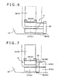
- the whole of the working oil tank 8 may be formed as the small height portion 8b, as shown in Fig. 6 .
- the exhaust gas after-treatment device 11 can be made longer in the longitudinal direction and hence it is possible to further improve the exhaust gas purifying performance.
- the small height portion 8b is formed in only the working oil tank 8 in the above embodiment.
- the small height portion 8b may be formed in at least one of the working oil tank 8 and the fuel tank 9 both disposed adjacent to the hydraulic pump 7.
- small height portions 8b and 9b and large height portions 8c and 9c may be formed in the tanks 8 and 9 respectively, and the exhaust gas after-treatment device 11 can be disposed on the small height portions 8b and 9b.
- the position of an upper portion of the first case 21 and that of the second case 22 are made different from each other by adjusting the height positions of both cases each having a circular section.
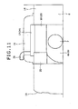
- a first case 23 and a second case 24 each having an elliptic section, as shown in Figs. 8 to 11 .
- An exhaust gas after-treatment device 26 used in this embodiment mainly includes a first case 23 disposed between the top plate 14 and the hydraulic pump 7, a second case 24 disposed between the bonnet 16 and the hydraulic pump 7, and a connecting section 25 for connecting rear end portions of both cases 23 and 24 with each other.
- the most part of the first case 23 is disposed right outside the formation range of the opening 14a, and the remaining part thereof is positioned so as to overlap the formation range of the opening 14a.
- the first case 23 is disposed so that exhaust gas flows longitudinally, and its section orthogonal to the exhaust gas flowing direction is in an elliptic shape with the major axis thereof in the right and left direction.
- the second case 24 is positioned inside the opening 14a, as seen from above, so that the whole thereof lies within the formation range of the opening 14a.
- the second case 24 is disposed so that exhaust gas flows longitudinally therein, and its' section orthogonal to the exhaust gas flowing direction is in an elliptic shape with the major axis thereof in the vertical direction. Further, the second case 24 and the first case 23 are almost equal in sectional area and respective lower surfaces lie at almost equal heights.
- a limited space between the base frame 4 and the guard panel 12 can be utilized effectively by adjusting the direction of the maximum length (major axis) in sectional shape in conformity with the expanse of the space between the guard panel 12 and the base frame 4.
- the sectional shape of the second treatment section 18 since the sectional shape of the second treatment section 18 is made vertically long, the area over the base frame 4 required for disposing the second treatment section 18 can be made small and hence the side space of the second treatment section 18 can be utilized effectively.
- the present invention provides a construction machine having a working attachment, the construction machine including: a base frame for supporting the working attachment so as to be raised and lowered; an engine installed on the base frame; an exhaust gas after-treatment device able to purify exhaust gas from the engine while the exhaust gas flows therethrough; and a guard panel installed over the base frame so as to cover the engine and the exhaust gas after-treatment device, wherein the exhaust gas after-treatment device includes a first treatment section having a filter able to collect dust contained in the exhaust gas from the engine and a second treatment section having a catalyst for decomposing nitrogen oxides contained in the exhaust gas treated by the first treatment section, the guard panel includes a top plate, the top plate being disposed substantially in parallel with the base frame and having an opening in a portion thereof corresponding to the engine, and a bonnet formed so as to project upwards from the top plate and cover the opening, one of the first and second treatment sections is disposed lower than the top plate, and at least a part of the other treatment section is disposed higher than the top plate through the opening and lower
- the other treatment section since at least a part of the other treatment section is disposed higher than the top plate and lower than the bonnet, it is possible to effectively utilize the limited space between the base frame and the guard panel.
- the exhaust gas after-treatment device can be disposed by effectively utilizing the vertical space within the existent bonnet even without forming a projecting portion on the top plate.
- the exhaust gas after-treatment device can be disposed while avoiding an increase of height and hence avoiding narrowing of the operator's visual field.
- the first and second treatment sections are disposed so that an exhaust gas flow passing through the interior of each of the treatment sections faces in the horizontal direction, have almost equal circular sectional shapes as sectional shapes orthogonal to the exhaust gas flowing direction, and are mounted at height positions different from each other.
- the first and second treatment sections of the same sectional shape have different height positions. And therefore, the cost required for fabricating each treatment section can be reduced as compared with the case where the first and second treatment sections are formed in a special sectional shape (e.g., ellipse) for forming a part positioned higher than the top plate on the other treatment section.
- a special sectional shape e.g., ellipse
- the treatment section disposed at a higher position out of both treatment sections can be disposed within the opening as seen from above.
- one of both treatment sections which is disposed at a higher position can be disposed as high as possible within the range that it is housed in the bonnet. And the space under the treatment section can be effectively utilized.
- the first and second treatment sections are disposed so that an exhaust gas flow passing through the interior of each of the treatment sections faces in the horizontal direction and so that respective lower surfaces lie at almost equal height positions.
- the limited space between the base frame and the guard panel can be utilized effectively by adjusting the direction of the maximum length in each sectional shape in conformity with the expanse of the space between the guard panel and the base frame.
- the upper portion of the other treatment section can be positioned higher than the top plate through the opening and lower than the bonnet.
- a sectional shape of the one treatment section orthogonal to the exhaust gas flowing direction may be horizontally long
- a sectional shape of the other treatment section orthogonal to the exhaust gas flowing direction may be vertically long
- the other treatment section may be disposed within the opening as seen from above.
- the entire upper portion of the other treatment section having a vertically long sectional shape, out of both treatment sections, can be disposed higher than the top plate through the opening and lower than bonnet.
- the sectional shape of the other treatment section is vertically long, the area over the base frame required for disposing the other treatment section (the area of the other treatment section as seen from above) can be made small and hence it becomes possible to effectively utilize the side space of the other treatment section accordingly.
- the treatment sections are disposed inside and outside of the opening respectively so as to sandwich a part of an edge of the opening therebetween as seen from above and are disposed so that the part of the edge of the opening sandwiched by the treatment sections and the exhaust gas flowing direction in each of the treatment sections run along each other.
- the other treatment section can be positioned inside the opening as seen from above while disposing one and the other treatment sections at positions as close as possible so that the exhaust gas slowing directions in both treatment sections run along each other. Consequently, the vertical space in the guard panel can be utilized effectively by utilizing the difference in height between the bonnet and the top plate.
- the first and second treatment sections can be disposed so that the exhaust gas flowing direction in the first treatment section and the exhaust gas flowing direction in the second treatment section are substantially parallel to each other.
- the whole of the exhaust gas after-treatment device can be disposed in a more compact form between the guard panel and the base plate by aligning the exhaust gas flowing directions in the first and second treatment sections.
- At least one of the treatment sections is disposed over a hydraulic pump connected to the engine.
- both treatment sections can be disposed by utilizing the space between the hydraulic pump and the guard panel.
- the exhaust gas after-treatment device can be disposed by effectively utilizing the existing space between the hydraulic pump and the bonnet.
- both treatment sections can be disposed over the hydraulic pump.
- the construction machine further includes a tank device, the tank device being disposed adjacently to the hydraulic pump on the base frame and having at least one of a working oil tank and a fuel tank, the tank device having a small height portion at at least a part thereof on the hydraulic pump side, the small height portion having an upper surface located at a height position almost equal to or lower than an upper end of the hydraulic pump, and at least one of the treatment sections is disposed over the small height portion and the hydraulic pump.
- each treatment section can be expanded in the horizontal direction by forming the small height portion, so that the exhaust gas flowing path length in each of the treatment sections can be made longer. Consequently, it is possible to further improve the exhaust gas purifying performance.
- the present invention it is possible to dispose the exhaust gas after-treatment device while suppressing an increase of height and hence suppressing narrowing of the operator's visual field.
Landscapes
- Engineering & Computer Science (AREA)
- General Engineering & Computer Science (AREA)
- Chemical & Material Sciences (AREA)
- Mechanical Engineering (AREA)
- Structural Engineering (AREA)
- Civil Engineering (AREA)
- Combustion & Propulsion (AREA)
- Mining & Mineral Resources (AREA)
- Transportation (AREA)
- Chemical Kinetics & Catalysis (AREA)
- Exhaust Gas After Treatment (AREA)
- Processes For Solid Components From Exhaust (AREA)
- Component Parts Of Construction Machinery (AREA)
- Exhaust Gas Treatment By Means Of Catalyst (AREA)
- Superstructure Of Vehicle (AREA)
- Cooling, Air Intake And Gas Exhaust, And Fuel Tank Arrangements In Propulsion Units (AREA)
Abstract
Description
- The present invention relates to a construction machine provided with an exhaust gas after-treatment device for purifying exhaust gas from an engine.
- Heretofore, there has been know a construction machine provided with a base frame which supports a working attachment so as to be raised and lowered, an engine installed on the base frame, and a guard panel for covering over the base frame.
- In construction machines of this type it has recently been desired that an exhaust gas after-treatment device for purifying exhaust gas from an engine be installed on a base frame.
- More particularly, the aforesaid exhaust gas after-treatment device has a DPF (Diesel Particulate Filter) for decreasing the amount of dust such as soot and mist contained in the engine exhaust gas and also has a reduction catalyst for decreasing the amount of NOx contained in the exhaust gas (see, for example,
Patent Documents 1 and 2). - However, since the engine and related peripheral devices (e.g., hydraulic systems) are disposed in a planarly massed layout on the base frame, it is difficult to newly ensure on the base frame a space as a planar space for disposing the exhaust gas after-treatment device.
- One countermeasure is to ensure a new space over the base frame. However, with a mere installation of the exhaust gas after-treatment device over the engine and a peripheral device thereof, not only the construction machine itself becomes larger in height, but also there results the problem that the visual field from the operator becomes narrow.
- [Patent Document 1] Japanese Patent Laid-Open Publication
No.2003-90214 - [Patent Document 2] Japanese Patent Laid-Open Publication
No.2003-120277 - The present invention has been accomplished in view of the above-mentioned problem and it is an object of the invention to provide a construction machine which permits an exhaust gas after-treatment device to be disposed while avoiding an increase of height and hence avoiding narrowing of the operator's visual field.
- In order to avoid the foregoing problem, the present invention provides a construction machine having a working attachment, the construction machine including: a base frame for supporting the working attachment so as to be raised and lowered; an engine installed on the base frame; an exhaust gas after-treatment device able to purify exhaust gas from the engine while the exhaust gas flows therethrough; and a guard panel installed over the base frame so as to cover the engine and the exhaust gas after-treatment device, wherein the exhaust gas after-treatment device includes a first treatment section having a filter able to collect dust contained in the exhaust gas from the engine and a second treatment section having a catalyst for decomposing nitrogen oxides contained in the exhaust gas treated by the first treatment section, the guard panel includes a top plate, the top plate being disposed substantially in parallel with the base frame and having an opening in a portion thereof corresponding to the engine, and a bonnet formed so as to project upwards from the top plate and cover the opening, one of the first and second treatment sections is disposed lower than the top plate, and at least a part of the other treatment section is disposed higher than the top plate through the opening and lower than the bonnet.
- According to the present invention, an exhaust gas after-treatment device can be disposed while suppressing an increase of height and hence suppressing narrowing of the operator's visual field.
-
-
Fig. 1 is a perspective view showing an upper rotating body of a hydraulic excavator according to an embodiment of the present invention. -
Fig. 2 is a plan view of the upper rotating body inFig. 1 with both a guard panel and exhaust gas after-treatment device omitted. -
Fig. 3 is a perspective view showing a state in which an exhaust gas after-treatment device is disposed on the upper rotating body ofFig. 2 . -
Fig. 4 is a rear view of the upper rotating body ofFig. 3 . -
Fig. 5 is a plan view thereof. -
Fig. 6 is a diagram corresponding toFig. 5 , showing another embodiment of the present invention. -
Fig. 7 is a diagram corresponding toFig. 5 , showing a further embodiment of the present invention. -
Fig. 8 is a partially enlarged perspective view of an upper rotating body according to a still further embodiment of the present invention. -
Fig. 9 is a plan view of an upper rotating body shown inFig. 6 . -
Fig. 10 is a rear view thereof. -
Fig. 11 is a side view thereof. - Preferred embodiments of the present invention will be described below with reference to the drawings.
-
Fig. 1 is a perspective view showing an upper rotating body of a hydraulic excavator according to an embodiment of the present invention.Fig. 2 is a plan view of the upper rotating body ofFig. 1 with both a guard panel and exhaust gas after-treatment device omitted.Fig. 3 is a perspective view showing a state in which an exhaust gas after-treatment device is disposed on the upper rotating body ofFig. 2 . - Referring to
Figs. 1 to 3 , ahydraulic excavator 1, is provided with a crawler type lower traveling body (not shown), an upper rotatingbody 2 mounted rotatably on the lower traveling body, and a working attachment 3 (seeFig. 2 ) supported so as to be raised and lowered with respect to the upper rotatingbody 2. - The upper rotating
body 2 is provided with a base frame 4 installed on the lower traveling body, aguard panel 12 which covers over the base frame 4, as well as acabin 5, anengine 6, ahydraulic pump 7, aworking oil tank 8, afuel tank 9, acounterweight 10, and an exhaust gas after-treatment device 11 (seeFig. 3 ), which are all installed on the base frame 4. In the following description it is assumed that the direction from front to rear and the direction from right to left as seen from an operator sitting on an operator's seat (not shown) within thecabin 5 are longitudinal and transverse directions, respectively, of the upper rotatingbody 2. - A pair of left and right
vertical plates attachment 3 is supported between front portions of thevertical plates cabin 5 is installed at a left front position of the leftvertical plate 4a. - The
engine 6 is installed on thevertical plates engine 6 includes anengine body 6a and an output shaft 6b projecting rightwards from a right end face of theengine body 6a. Aright end portion of theengine body 6a is disposed substantially above the rightvertical plate 4b. - The
hydraulic pump 7 is connected transversely to the output shaft 6b through a coupling (not shown) or the like so as to become capable of being operated with the power of theengine 6. As a result, thehydraulic pump 7 is disposed in an area from above the rightvertical plate 4b to the right side of the same plate (seeFig. 2 ). - In this embodiment, the
working oil tank 8 and thefuel tank 9 are disposed longitudinally in a line at the right-hand position of the rightvertical plate 4b. That is, thefuel tank 9 is disposed in the front and theworking oil tank 8 is disposed in the rear. As a result, theworking oil tank 8 is disposed adjacently to and in front of thehydraulic pump 7. - The working
oil tank 8 includes, as integral components, alarge height portion 8c having a height almost equal to the height of thecounterweight 10, and asmall height portion 8b formed behind thelarge height portion 8c and having anupper surface 8a, theupper surface 8a having a height H5 almost equal to or lower than the height H4 (seeFig. 4 ) of thehydraulic pump 7. - The
counterweight 10 is provided along a rear edge portion of the base frame 4. That is, thecounterweight 10 confronts theworking oil tank 8 longitudinally with thehydraulic pump 7 therebetween. The exhaust gas after-treatment device 11, which is for purifying exhaust gas from theengine 6, is installed between thecounterweight 10 and theworking oil tank 8 and over thehydraulic pump 7. As to the structure of the exhaust gas after-treatment device 11, it will be described later. - The
guard panel 12 is installed over the base panel 4 so as to cover theengine 6,hydraulic pump 7, workingoil tank 8,fuel tank 9 and exhaust gas after-treatment device 11. More specifically, theguard panel 12 includes atop plate 14 disposed substantially in parallel with the base frame 4, a pair ofside plates 15 provided at right and left edge portions of the top plate 14 (only the right one is shown inFig. 1 ), and abonnet 16 provided so as to project upwards from thetop plate 14. - The
top plate 14 is installed longitudinally within from thecounterweight 10 to thecabin 5 so as to cover theengine 6,hydraulic pump 7, workingoil tank 8,fuel tank 9 and exhaust gas after-treatment device 11. Thetop plate 14 is installed at a height position almost equal to thecounterweight 10. - The
top plate 14 is formed with an opening 14a (seeFig. 2 ) opening through the plate at a position corresponding to theengine 6. Maintenance of the engine 6 (particularly of theengine body 6a) is performed through the opening 14a. - The
bonnet 16 is attached to an upper surface of thetop plate 14 through a hinge (not shown) so as to permit opening or closing of the opening 14a. Thebonnet 16 is formed in the shape of a vessel which swells upwards in its closed state, so that the inner space of theguard panel 12 is expanded upwards by a volume corresponding to the inner space of thebonnet 16. - Now, a description will be given below about a relation in height among the
guard panel 12,engine 6 andhydraulic pump 7 with reference toFig. 4 . Height positions to be referred to below are the height positions from the base frame 4. - In this embodiment, the height H1 of the
engine body 6a is almost equal to or a little higher than the height H2 of thetop plate 14 and is lower than the height H3 of thebonnet 16. The height H4 of thehydraulic pump 7 is lower than each of the heights H1 to H3. Between thehydraulic pump 7 and theguard panel 12 is disposed the exhaust gas after-treatment device 11. -
Fig. 4 is a rear view of the upper rotating body ofFig. 3 andFig. 5 is a plan view thereof. - Referring to
Figs. 3 to 5 , the exhaust gas after-treatment device 11 is provided with a first treatment section (one treatment section) 17 connected to an exhaust passage of theengine 6, a connectingsection 19 which receives exhaust gas discharged from thefirst treatment section 17, a second treatment section (the other treatment section) 18 which receives exhaust gas discharged from the connectingsection 19, and an exhaust pipe 20 (seeFig. 1 ) for discharging the exhaust gas discharged from thesecond treatment section 18 to the exterior of theguard panel 12. Theexhaust pipe 20 extends from thesecond treatment section 18 to the outside of theguard panel 12 through the guard panel 12 (bonnet 16). - The
first treatment section 17 has a filter (Diesel Particulate Filter, hereinafter referred to as DPF, not shown) for removing soot and mist contained in the exhaust gas from theengine 6, and afirst case 21 for housing the DPF therein. The DPF has the ability to collect soot, etc. contained in the exhaust gas flowing through the interior thereof, and the dust collecting ability can be regenerated by burning the collected dust at a high temperature. - The
first case 21 is a cylindrical member extending in the longitudinal direction and having a circular section and it houses the DPF therein. As shown inFig. 4 , thefirst case 21 is disposed lower than thetop plate 14 and higher than thehydraulic pump 7. As shown inFigs. 4 and5 , thefirst case 21, as seen from above, is positioned outside theopening 14a of thetop plate 14 and along a right edge of theopening 14a of thetop plate 14. - The
second treatment section 18 has a catalyst layer (not shown) for removing NOx contained in the exhaust gas from theengine 6, and asecond case 22 which houses the catalyst layer therein. This catalyst layer allows the exhaust gas sprayed with aqueous urea to pass through the interior thereof, thereby inducing a so-called denitration reaction to decompose nitrogen oxides (NOx) contained in the exhaust gas into nitrogen, oxygen and water. - The
second case 22 is a cylindrical member extending in the longitudinal direction and having a circular section and it contains the aforesaid catalyst layer. A sectional area of thesecond case 22 is set almost equal to the sectional area of thefirst case 21 and thesecond case 22 is disposed at a higher position than thefirst case 21. More specifically, in this embodiment, an upper surface of thesecond case 22 is disposed at a position higher than thetop plate 14 and lower than thebonnet 16, and therefore an upper potion of thesecond case 22 is disposed higher than thetop plate 14 through theopening 14a and lower than thebonnet 16. A vertex portion of thesecond case 22 is positioned higher than an upper surface of theengine body 6a. - As seen from above, as shown in
Fig. 5 , thesecond case 22 is disposed within theopening 14a of thetop plate 14. More specifically, thesecond case 22, as seen from above, is disposed within theopening 14a along thefirst case 21, and along the right edge of theopening 14a so as to sandwich the right edge of theopening 14a between thesecond case 22 and thefirst case 21. Further, thesecond case 22 is disposed. Therefore, it is possible to effectively utilize the vertical space from, thehydraulic pump 7 up to theguard panel 12 which space was expanded upwards by a volume corresponding to thebonnet 16. - Although in this embodiment a description is being given about the structure wherein the flowing direction of exhaust gas in the
first case 21 and that in thesecond case 22 are longitudinally parallel, it is not always necessary that both flowing directions be parallel. For example, the first andsecond cases - The connecting
portion 19 supports the front ends of the first andsecond cases first case 21 is positioned higher than that of thesecond case 22. The connectingportion 19 is mounted onto theupper surface 8a of the workingoil tank 8. The dimension from a front end face of the connectingsection 19 to a rear end face of each of thecases counterweight 10 and a rear face of thelarge height portion 8c of the workingoil tank 8. - According to the above embodiment, as described above, since an upper portion of the
second treatment section 18 is disposed higher than thetop plate 14 and lower than thebonnet 16, it is possible to effectively utilize the narrow space between the base frame 4 andguard panel 12. - That is, in the area inside the
opening 14a, as compared with the other area, the height from the base frame 4 to theguard panel 12 becomes higher by the projecting length of thebonnet 16. And the upper portion of thesecond treatment section 18 is positioned higher than thetop plate 14 through theopening 14a, and therefore the exhaust gas after-treatment device 11 can be disposed by effectively utilizing the vertical space within theexistent bonnet 16 without forming a new projecting portion on thetop plate 14. - And the exhaust gas after-
treatment device 11 can be consequently disposed while avoiding an increase of height and hence avoiding narrowing of the operator's visual field. - As in the above embodiment, the first and
second treatment sections second treatment sections first treatment section 17 thesecond treatment section 18 of the almost same section are installed at different height positions, it is possible to reduce the cost required for fabricating thetreatment sections treatment sections second treatment section 18 positioned higher than thetop plate 14. - As in the above embodiment, when the
treatment section 18 installed at a higher position of thetreatment sections opening 14a as seen from above, thesecond treatment section 18 positioned higher can be positioned as high as possible within the range that it is housed in thebonnet 16, so that the space under thetreatment section 18 can be effectively utilized accordingly. - As in the above embodiment, when the
treatment sections opening 14a respectively so as to sandwich the right edge of theopening 14a therebetween as seen from above, and are disposed so that the right edge of theopening 14a sandwiched by thetreatment sections treatment sections second treatment section 18 is disposed inside the opening while disposing bothtreatment sections guard panel 12 can be utilized effectively by utilizing the difference in height between thebonnet 16 and thetop plate 14. - As in the above embodiment, according to the structure wherein the first and
second treatment sections treatment device 11 can be disposed in a more compact form between theguard panel 12 and the base frame 4. - Further, by forming the
small height portion 8b in the workingoil tank 8 as in the above embodiment, the space for disposing the exhaust gas after-treatment device 11 can be expanded in the horizontal direction and hence the exhaust gas flowing path can be made longer for each of the first andsecond treatment sections - Although in the above embodiment only the rear portion of the working
oil tank 8 is formed as thesmall height portion 8b and the exhaust gas after-treatment device 11 is disposed over thesmall height portion 8b, the whole of the workingoil tank 8 may be formed as thesmall height portion 8b, as shown inFig. 6 . - As a result of the
small height portion 8b over the entire upper surface of the workingoil tank 8, the exhaust gas after-treatment device 11 can be made longer in the longitudinal direction and hence it is possible to further improve the exhaust gas purifying performance. - The
small height portion 8b is formed in only the workingoil tank 8 in the above embodiment. Instead of the workingoil tank 8, thesmall height portion 8b may be formed in at least one of the workingoil tank 8 and thefuel tank 9 both disposed adjacent to thehydraulic pump 7. As shown inFig. 7 , in the case where the workingoil tank 8 and thefuel tank 9 are juxtaposed right and left in front of thehydraulic pump 7,small height portions large height portions tanks treatment device 11 can be disposed on thesmall height portions - In the above embodiment, the position of an upper portion of the
first case 21 and that of thesecond case 22 are made different from each other by adjusting the height positions of both cases each having a circular section. However, there also may be adopted afirst case 23 and asecond case 24 each having an elliptic section, as shown inFigs. 8 to 11 . - An exhaust gas after-
treatment device 26 used in this embodiment mainly includes afirst case 23 disposed between thetop plate 14 and thehydraulic pump 7, asecond case 24 disposed between thebonnet 16 and thehydraulic pump 7, and a connectingsection 25 for connecting rear end portions of bothcases - As shown in detail in
Fig. 9 , the most part of thefirst case 23 is disposed right outside the formation range of theopening 14a, and the remaining part thereof is positioned so as to overlap the formation range of theopening 14a. Thefirst case 23 is disposed so that exhaust gas flows longitudinally, and its section orthogonal to the exhaust gas flowing direction is in an elliptic shape with the major axis thereof in the right and left direction. - On the other hand, the
second case 24 is positioned inside theopening 14a, as seen from above, so that the whole thereof lies within the formation range of theopening 14a. Thesecond case 24 is disposed so that exhaust gas flows longitudinally therein, and its' section orthogonal to the exhaust gas flowing direction is in an elliptic shape with the major axis thereof in the vertical direction. Further, thesecond case 24 and thefirst case 23 are almost equal in sectional area and respective lower surfaces lie at almost equal heights. - Thus, in this embodiment, since the elliptic sectional shape is adopted for each of the
cases small height portion 8b (seeFig. 3 ) in the workingoil tank 8. However the effect of this configuration is not to exclude thesmall height portion 8b. - According to the above embodiment, when the space under the
first treatment section 17 and that under thesecond treatment section 18 are limited to almost equal height positions, a limited space between the base frame 4 and theguard panel 12 can be utilized effectively by adjusting the direction of the maximum length (major axis) in sectional shape in conformity with the expanse of the space between theguard panel 12 and the base frame 4. In the above embodiment, since the sectional shape of thesecond treatment section 18 is made vertically long, the area over the base frame 4 required for disposing thesecond treatment section 18 can be made small and hence the side space of thesecond treatment section 18 can be utilized effectively. - Inventions having the following structures are mainly included in the concrete embodiments described above.
- The present invention provides a construction machine having a working attachment, the construction machine including: a base frame for supporting the working attachment so as to be raised and lowered; an engine installed on the base frame; an exhaust gas after-treatment device able to purify exhaust gas from the engine while the exhaust gas flows therethrough; and a guard panel installed over the base frame so as to cover the engine and the exhaust gas after-treatment device, wherein the exhaust gas after-treatment device includes a first treatment section having a filter able to collect dust contained in the exhaust gas from the engine and a second treatment section having a catalyst for decomposing nitrogen oxides contained in the exhaust gas treated by the first treatment section, the guard panel includes a top plate, the top plate being disposed substantially in parallel with the base frame and having an opening in a portion thereof corresponding to the engine, and a bonnet formed so as to project upwards from the top plate and cover the opening, one of the first and second treatment sections is disposed lower than the top plate, and at least a part of the other treatment section is disposed higher than the top plate through the opening and lower than the bonnet.
- According to the present invention, since at least a part of the other treatment section is disposed higher than the top plate and lower than the bonnet, it is possible to effectively utilize the limited space between the base frame and the guard panel.
- That is, in the inside of the opening as compared with the other area, the height from the base frame to the guard panel becomes higher by the projecting distance of the bonnet, but at least a part of the other treatment section is positioned higher than the top plate through the opening, and therefore, the exhaust gas after-treatment device can be disposed by effectively utilizing the vertical space within the existent bonnet even without forming a projecting portion on the top plate.
- Thus, the exhaust gas after-treatment device can be disposed while avoiding an increase of height and hence avoiding narrowing of the operator's visual field.
- In the above construction machine, preferably, the first and second treatment sections are disposed so that an exhaust gas flow passing through the interior of each of the treatment sections faces in the horizontal direction, have almost equal circular sectional shapes as sectional shapes orthogonal to the exhaust gas flowing direction, and are mounted at height positions different from each other.
- That is, if one of the treatment sections which is disposed at a higher position is the other treatment section, and at least a. part of this treatment section is positioned higher than the top plate, the first and second treatment sections of the same sectional shape have different height positions. And therefore, the cost required for fabricating each treatment section can be reduced as compared with the case where the first and second treatment sections are formed in a special sectional shape (e.g., ellipse) for forming a part positioned higher than the top plate on the other treatment section.
- In case of disposing the first and second treatment sections at different positions, the treatment section disposed at a higher position out of both treatment sections can be disposed within the opening as seen from above.
- By so doing, one of both treatment sections which is disposed at a higher position can be disposed as high as possible within the range that it is housed in the bonnet. And the space under the treatment section can be effectively utilized.
- On the other hand, preferably, the first and second treatment sections are disposed so that an exhaust gas flow passing through the interior of each of the treatment sections faces in the horizontal direction and so that respective lower surfaces lie at almost equal height positions.
- According to this structure, in the case where the spaces below the first and second treatment sections are limited at almost the same height positions, the limited space between the base frame and the guard panel can be utilized effectively by adjusting the direction of the maximum length in each sectional shape in conformity with the expanse of the space between the guard panel and the base frame.
- More specifically, when one of the first and second treatment sections which one is larger in the maximum vertical dimension in its sectional shape orthogonal to the flowing direction is the other treatment section, the upper portion of the other treatment section can be positioned higher than the top plate through the opening and lower than the bonnet.
- Further, a sectional shape of the one treatment section orthogonal to the exhaust gas flowing direction may be horizontally long, a sectional shape of the other treatment section orthogonal to the exhaust gas flowing direction may be vertically long, and the other treatment section may be disposed within the opening as seen from above.
- By so doing, the entire upper portion of the other treatment section having a vertically long sectional shape, out of both treatment sections, can be disposed higher than the top plate through the opening and lower than bonnet. In this structure, since the sectional shape of the other treatment section is vertically long, the area over the base frame required for disposing the other treatment section (the area of the other treatment section as seen from above) can be made small and hence it becomes possible to effectively utilize the side space of the other treatment section accordingly.
- In the above construction machine, preferably, the treatment sections are disposed inside and outside of the opening respectively so as to sandwich a part of an edge of the opening therebetween as seen from above and are disposed so that the part of the edge of the opening sandwiched by the treatment sections and the exhaust gas flowing direction in each of the treatment sections run along each other.
- By so doing, the other treatment section can be positioned inside the opening as seen from above while disposing one and the other treatment sections at positions as close as possible so that the exhaust gas slowing directions in both treatment sections run along each other. Consequently, the vertical space in the guard panel can be utilized effectively by utilizing the difference in height between the bonnet and the top plate.
- The first and second treatment sections can be disposed so that the exhaust gas flowing direction in the first treatment section and the exhaust gas flowing direction in the second treatment section are substantially parallel to each other.
- By so doing, the whole of the exhaust gas after-treatment device can be disposed in a more compact form between the guard panel and the base plate by aligning the exhaust gas flowing directions in the first and second treatment sections.
- Preferably, at least one of the treatment sections is disposed over a hydraulic pump connected to the engine.
- By so doing, at least one of both treatment sections can be disposed by utilizing the space between the hydraulic pump and the guard panel. Particularly in case of disposing both treatment sections at different heights, by disposing the foregoing one treatment section below the other treatment section while disposing the other treatment section over the hydraulic pump and adjacently to the engine, the exhaust gas after-treatment device can be disposed by effectively utilizing the existing space between the hydraulic pump and the bonnet. On the other hand, in case of positioning the lower surfaces of both treatment sections at almost equal heights, both treatment sections can be disposed over the hydraulic pump.
- Further, there may be adopted a structure wherein the construction machine further includes a tank device, the tank device being disposed adjacently to the hydraulic pump on the base frame and having at least one of a working oil tank and a fuel tank, the tank device having a small height portion at at least a part thereof on the hydraulic pump side, the small height portion having an upper surface located at a height position almost equal to or lower than an upper end of the hydraulic pump, and at least one of the treatment sections is disposed over the small height portion and the hydraulic pump.
- By so doing, the installation space of each treatment section can be expanded in the horizontal direction by forming the small height portion, so that the exhaust gas flowing path length in each of the treatment sections can be made longer. Consequently, it is possible to further improve the exhaust gas purifying performance.
- According to the present invention it is possible to dispose the exhaust gas after-treatment device while suppressing an increase of height and hence suppressing narrowing of the operator's visual field.
Claims (9)
- A construction machine having a working attachment, said construction machine comprising:a base frame for supporting said working attachment so as to be raised and lowered;an engine installed on said base frame;an exhaust gas after-treatment device able to purify exhaust gas from said engine while the exhaust gas flows therethrough; anda guard panel installed over said base frame so as to cover said engine and said exhaust gas after-treatment device,wherein said exhaust gas after-treatment device includes a first treatment section having a filter able to collect dust contained in the exhaust gas from said engine and a second treatment section having a catalyst for decomposing nitrogen oxides contained in the exhaust gas treated by said first treatment section,said guard panel includes a top plate, said top plate being disposed substantially in parallel with said base frame and having an opening in a portion thereof corresponding to said engine, and a bonnet formed so as to project upwards from said top plate and cover said opening,one of said first and second treatment sections is disposed lower than said top plate, and at least a part of the other treatment section is disposed higher than said top plate through said opening and lower than said bonnet.
- The construction machine according to claim 1, wherein said first and second treatment sections are disposed so that an exhaust gas flow passing through the interior of each of said treatment sections faces in the horizontal direction, have almost equal circular sectional shapes as sectional shapes orthogonal to said exhaust gas flowing direction, and are mounted at height positions different from each other.
- The construction machine according to claim 2, wherein one of said first and second treatment sections, which one is disposed at a higher position, is disposed within said opening as seen from above.
- The construction machine according to claim 1, wherein said first and second treatment sections are disposed so that an exhaust gas flow passing through the interior of each of said treatment sections faces in the horizontal direction and so that respective lower surfaces lie at almost equal height positions.
- The construction machine according to claim 4, wherein a sectional shape of said one treatment section orthogonal to the exhaust gas flowing direction is horizontally long, a sectional shape of the other treatment section orthogonal to the exhaust gas flowing direction is vertically long, and the other treatment section is disposed within said opening as seen from above.
- The construction machine according to any of claims 1 to 5, wherein said treatment sections are disposed inside and outside of said opening respectively so as to sandwich a part of an edge of said opening therebetween as seen from above and are disposed so that the part of the edge of said opening sandwiched by said treatment sections and the exhaust gas flowing direction in each of said treatment sections run along each other.
- The construction machine according to any of claims 1 to 6, wherein said first and second treatment sections are disposed so that the exhaust gas flowing direction in said first treatment section and the exhaust gas flowing direction in said second treatment section are substantially parallel to each other.
- The construction machine according to any of claims 1 to 7, wherein at least one of said treatment sections is disposed over a hydraulic pump connected to said engine.
- The construction machine according to claim 8, further comprising a tank device, said tank device being disposed adjacently to said hydraulic pump on said base frame and having at least one of a working oil tank and a fuel tank,
said tank device having a small height portion at at least a part thereof on the hydraulic pump side, said small height portion having an upper surface located at a height position almost equal to or lower than an upper end of said hydraulic pump, and
at least one of said treatment sections is disposed over said small height portion and said hydraulic pump.
Applications Claiming Priority (2)
| Application Number | Priority Date | Filing Date | Title |
|---|---|---|---|
| JP2007274087A JP5012406B2 (en) | 2007-10-22 | 2007-10-22 | Construction machinery |
| PCT/JP2008/065542 WO2009054184A1 (en) | 2007-10-22 | 2008-08-29 | Construction machine |
Publications (3)
| Publication Number | Publication Date |
|---|---|
| EP2202391A1 true EP2202391A1 (en) | 2010-06-30 |
| EP2202391A4 EP2202391A4 (en) | 2016-10-05 |
| EP2202391B1 EP2202391B1 (en) | 2017-08-23 |
Family
ID=40579291
Family Applications (1)
| Application Number | Title | Priority Date | Filing Date |
|---|---|---|---|
| EP08841353.9A Not-in-force EP2202391B1 (en) | 2007-10-22 | 2008-08-29 | Construction machine |
Country Status (5)
| Country | Link |
|---|---|
| US (1) | US8407991B2 (en) |
| EP (1) | EP2202391B1 (en) |
| JP (1) | JP5012406B2 (en) |
| CN (1) | CN101835963B (en) |
| WO (1) | WO2009054184A1 (en) |
Cited By (2)
| Publication number | Priority date | Publication date | Assignee | Title |
|---|---|---|---|---|
| EP2307177A1 (en) * | 2008-05-15 | 2011-04-13 | The Boeing Company | Robotic system including foldable robotic arm |
| EP2634314A4 (en) * | 2010-10-29 | 2017-12-27 | Kobelco Construction Machinery Co., Ltd. | Construction machine |
Families Citing this family (25)
| Publication number | Priority date | Publication date | Assignee | Title |
|---|---|---|---|---|
| JP5468393B2 (en) * | 2010-01-09 | 2014-04-09 | 日立建機株式会社 | Construction machinery |
| JP2011157721A (en) * | 2010-02-01 | 2011-08-18 | Kobe Steel Ltd | Construction machinery |
| JP2011231592A (en) * | 2010-04-30 | 2011-11-17 | Sumitomo (Shi) Construction Machinery Co Ltd | Exhaust device layout for construction machine |
| KR101455141B1 (en) * | 2011-02-01 | 2014-10-27 | 가부시키가이샤 고마쓰 세이사쿠쇼 | Construction machine |
| JP5667523B2 (en) * | 2011-06-10 | 2015-02-12 | 株式会社クボタ | Harvesting machine |
| KR101988412B1 (en) * | 2011-06-10 | 2019-06-12 | 가부시끼 가이샤 구보다 | Harvester |
| CN102996211B (en) * | 2011-09-15 | 2016-01-20 | 住友建机株式会社 | The exhaust device layout of construction plant |
| US9316136B2 (en) * | 2012-07-05 | 2016-04-19 | Komatsu Ltd. | Engine unit and work vehicle |
| JP5296913B1 (en) * | 2012-10-02 | 2013-09-25 | 株式会社小松製作所 | Engine unit |
| JP5501424B2 (en) * | 2012-10-16 | 2014-05-21 | 株式会社小松製作所 | Exhaust treatment unit |
| WO2014061295A1 (en) * | 2012-10-16 | 2014-04-24 | 株式会社小松製作所 | Hydraulic shovel |
| JP5526288B1 (en) * | 2012-10-26 | 2014-06-18 | 株式会社小松製作所 | Wheel loader |
| WO2014069026A1 (en) * | 2012-10-30 | 2014-05-08 | 株式会社小松製作所 | Construction vehicle equipped with exhaust-gas post-processing device |
| US8919486B2 (en) | 2013-02-15 | 2014-12-30 | Komatsu Ltd. | Hydraulic excavator |
| CN105051342B (en) * | 2013-03-15 | 2018-03-16 | 洋马株式会社 | Engine device |
| GB2515450B (en) * | 2013-03-18 | 2017-03-22 | Alexander Dennis Ltd | Passenger service vehicle |
| JP6262440B2 (en) * | 2013-04-08 | 2018-01-17 | 株式会社Kcm | Wheel loader |
| JP5624692B1 (en) * | 2013-04-26 | 2014-11-12 | 株式会社小松製作所 | Bulldozer |
| JP5914410B2 (en) * | 2013-05-17 | 2016-05-11 | 日立建機株式会社 | Construction machinery |
| DE112014000097B4 (en) * | 2014-08-08 | 2017-04-06 | Komatsu Ltd. | hydraulic excavators |
| JP2016050466A (en) * | 2014-09-02 | 2016-04-11 | 日立建機株式会社 | Small construction machinery |
| JP6285840B2 (en) * | 2014-09-30 | 2018-02-28 | 日立建機株式会社 | Construction machinery |
| JP5865474B2 (en) * | 2014-12-11 | 2016-02-17 | 株式会社クボタ | Harvesting machine |
| JP6632884B2 (en) * | 2015-03-20 | 2020-01-22 | 住友建機株式会社 | Small turning shovel |
| US10800225B2 (en) | 2016-08-03 | 2020-10-13 | Komatsu Ltd. | Working vehicle |
Family Cites Families (8)
| Publication number | Priority date | Publication date | Assignee | Title |
|---|---|---|---|---|
| JP2002317631A (en) * | 2001-04-23 | 2002-10-31 | Komatsu Ltd | Engine exhaust gas exhaust device |
| JP3978320B2 (en) * | 2001-07-31 | 2007-09-19 | 新キャタピラー三菱株式会社 | Construction machinery with built-in exhaust gas reduction device |
| JP4115120B2 (en) | 2001-08-06 | 2008-07-09 | 株式会社小松製作所 | Exhaust gas purification device for internal combustion engine |
| JP2003090214A (en) | 2001-09-19 | 2003-03-28 | Komatsu Ltd | Exhaust gas purification device for internal combustion engine |
| JP2005155404A (en) * | 2003-11-25 | 2005-06-16 | Komatsu Ltd | Exhaust gas purification device for internal combustion engine |
| JP4387983B2 (en) * | 2005-05-30 | 2009-12-24 | キャタピラージャパン株式会社 | Hydraulic oil tank structure of work machine |
| JP2007100351A (en) * | 2005-10-03 | 2007-04-19 | Hitachi Constr Mach Co Ltd | Working machine |
| JP4343900B2 (en) * | 2005-12-26 | 2009-10-14 | 日立建機株式会社 | Construction machinery |
-
2007
- 2007-10-22 JP JP2007274087A patent/JP5012406B2/en not_active Expired - Fee Related
-
2008
- 2008-08-29 WO PCT/JP2008/065542 patent/WO2009054184A1/en not_active Ceased
- 2008-08-29 US US12/682,193 patent/US8407991B2/en not_active Expired - Fee Related
- 2008-08-29 CN CN2008801126315A patent/CN101835963B/en not_active Expired - Fee Related
- 2008-08-29 EP EP08841353.9A patent/EP2202391B1/en not_active Not-in-force
Non-Patent Citations (1)
| Title |
|---|
| See references of WO2009054184A1 * |
Cited By (2)
| Publication number | Priority date | Publication date | Assignee | Title |
|---|---|---|---|---|
| EP2307177A1 (en) * | 2008-05-15 | 2011-04-13 | The Boeing Company | Robotic system including foldable robotic arm |
| EP2634314A4 (en) * | 2010-10-29 | 2017-12-27 | Kobelco Construction Machinery Co., Ltd. | Construction machine |
Also Published As
| Publication number | Publication date |
|---|---|
| US8407991B2 (en) | 2013-04-02 |
| CN101835963A (en) | 2010-09-15 |
| WO2009054184A1 (en) | 2009-04-30 |
| CN101835963B (en) | 2012-09-05 |
| JP2009103016A (en) | 2009-05-14 |
| US20100218488A1 (en) | 2010-09-02 |
| JP5012406B2 (en) | 2012-08-29 |
| EP2202391A4 (en) | 2016-10-05 |
| EP2202391B1 (en) | 2017-08-23 |
Similar Documents
| Publication | Publication Date | Title |
|---|---|---|
| EP2202391B1 (en) | Construction machine | |
| JP4900163B2 (en) | Construction machinery | |
| US8708087B2 (en) | Construction machine | |
| KR101583539B1 (en) | Exhaust gas purifying device | |
| EP2333260B1 (en) | Engine device | |
| EP2333263A1 (en) | Engine device | |
| WO2011152306A1 (en) | Work vehicle | |
| EP2799676B1 (en) | Work vehicle and wheel loader | |
| JP2021143614A (en) | Construction machine | |
| EP2336520A1 (en) | Engine device | |
| EP3020872B1 (en) | Construction machine | |
| CN103380017A (en) | Construction machine | |
| KR20180031045A (en) | Construction Machinery | |
| JP5635695B1 (en) | Work vehicle and wheel loader | |
| WO2014196395A1 (en) | Construction apparatus | |
| JP5914410B2 (en) | Construction machinery | |
| JP2020019402A (en) | Construction machine | |
| JP7025307B2 (en) | Construction machinery | |
| JP7271745B2 (en) | construction machinery | |
| JP6285840B2 (en) | Construction machinery | |
| CN210421207U (en) | Novel low-emission bulldozer | |
| JP7511435B2 (en) | Construction Machinery | |
| JP2017160639A (en) | Exhaust device for work machine | |
| JP2022065355A (en) | Construction machine |
Legal Events
| Date | Code | Title | Description |
|---|---|---|---|
| PUAI | Public reference made under article 153(3) epc to a published international application that has entered the european phase |
Free format text: ORIGINAL CODE: 0009012 |
|
| 17P | Request for examination filed |
Effective date: 20100330 |
|
| AK | Designated contracting states |
Kind code of ref document: A1 Designated state(s): AT BE BG CH CY CZ DE DK EE ES FI FR GB GR HR HU IE IS IT LI LT LU LV MC MT NL NO PL PT RO SE SI SK TR |
|
| AX | Request for extension of the european patent |
Extension state: AL BA MK RS |
|
| DAX | Request for extension of the european patent (deleted) | ||
| RA4 | Supplementary search report drawn up and despatched (corrected) |
Effective date: 20160905 |
|
| RIC1 | Information provided on ipc code assigned before grant |
Ipc: E02F 9/00 20060101ALI20160830BHEP Ipc: F01N 3/02 20060101ALI20160830BHEP Ipc: B01D 53/94 20060101ALI20160830BHEP Ipc: F01N 3/28 20060101AFI20160830BHEP |
|
| GRAP | Despatch of communication of intention to grant a patent |
Free format text: ORIGINAL CODE: EPIDOSNIGR1 |
|
| INTG | Intention to grant announced |
Effective date: 20170510 |
|
| GRAS | Grant fee paid |
Free format text: ORIGINAL CODE: EPIDOSNIGR3 |
|
| GRAA | (expected) grant |
Free format text: ORIGINAL CODE: 0009210 |
|
| AK | Designated contracting states |
Kind code of ref document: B1 Designated state(s): AT BE BG CH CY CZ DE DK EE ES FI FR GB GR HR HU IE IS IT LI LT LU LV MC MT NL NO PL PT RO SE SI SK TR |
|
| REG | Reference to a national code |
Ref country code: GB Ref legal event code: FG4D |
|
| REG | Reference to a national code |
Ref country code: CH Ref legal event code: EP |
|
| REG | Reference to a national code |
Ref country code: AT Ref legal event code: REF Ref document number: 921598 Country of ref document: AT Kind code of ref document: T Effective date: 20170915 |
|
| REG | Reference to a national code |
Ref country code: IE Ref legal event code: FG4D |
|
| REG | Reference to a national code |
Ref country code: DE Ref legal event code: R096 Ref document number: 602008051801 Country of ref document: DE |
|
| REG | Reference to a national code |
Ref country code: FR Ref legal event code: PLFP Year of fee payment: 10 |
|
| REG | Reference to a national code |
Ref country code: NL Ref legal event code: MP Effective date: 20170823 |
|
| REG | Reference to a national code |
Ref country code: LT Ref legal event code: MG4D |
|
| REG | Reference to a national code |
Ref country code: AT Ref legal event code: MK05 Ref document number: 921598 Country of ref document: AT Kind code of ref document: T Effective date: 20170823 |
|
| PG25 | Lapsed in a contracting state [announced via postgrant information from national office to epo] |
Ref country code: HR Free format text: LAPSE BECAUSE OF FAILURE TO SUBMIT A TRANSLATION OF THE DESCRIPTION OR TO PAY THE FEE WITHIN THE PRESCRIBED TIME-LIMIT Effective date: 20170823 Ref country code: SE Free format text: LAPSE BECAUSE OF FAILURE TO SUBMIT A TRANSLATION OF THE DESCRIPTION OR TO PAY THE FEE WITHIN THE PRESCRIBED TIME-LIMIT Effective date: 20170823 Ref country code: LT Free format text: LAPSE BECAUSE OF FAILURE TO SUBMIT A TRANSLATION OF THE DESCRIPTION OR TO PAY THE FEE WITHIN THE PRESCRIBED TIME-LIMIT Effective date: 20170823 Ref country code: FI Free format text: LAPSE BECAUSE OF FAILURE TO SUBMIT A TRANSLATION OF THE DESCRIPTION OR TO PAY THE FEE WITHIN THE PRESCRIBED TIME-LIMIT Effective date: 20170823 Ref country code: NL Free format text: LAPSE BECAUSE OF FAILURE TO SUBMIT A TRANSLATION OF THE DESCRIPTION OR TO PAY THE FEE WITHIN THE PRESCRIBED TIME-LIMIT Effective date: 20170823 Ref country code: AT Free format text: LAPSE BECAUSE OF FAILURE TO SUBMIT A TRANSLATION OF THE DESCRIPTION OR TO PAY THE FEE WITHIN THE PRESCRIBED TIME-LIMIT Effective date: 20170823 Ref country code: NO Free format text: LAPSE BECAUSE OF FAILURE TO SUBMIT A TRANSLATION OF THE DESCRIPTION OR TO PAY THE FEE WITHIN THE PRESCRIBED TIME-LIMIT Effective date: 20171123 |
|
| PG25 | Lapsed in a contracting state [announced via postgrant information from national office to epo] |
Ref country code: ES Free format text: LAPSE BECAUSE OF FAILURE TO SUBMIT A TRANSLATION OF THE DESCRIPTION OR TO PAY THE FEE WITHIN THE PRESCRIBED TIME-LIMIT Effective date: 20170823 Ref country code: BG Free format text: LAPSE BECAUSE OF FAILURE TO SUBMIT A TRANSLATION OF THE DESCRIPTION OR TO PAY THE FEE WITHIN THE PRESCRIBED TIME-LIMIT Effective date: 20171123 Ref country code: GR Free format text: LAPSE BECAUSE OF FAILURE TO SUBMIT A TRANSLATION OF THE DESCRIPTION OR TO PAY THE FEE WITHIN THE PRESCRIBED TIME-LIMIT Effective date: 20171124 Ref country code: LV Free format text: LAPSE BECAUSE OF FAILURE TO SUBMIT A TRANSLATION OF THE DESCRIPTION OR TO PAY THE FEE WITHIN THE PRESCRIBED TIME-LIMIT Effective date: 20170823 Ref country code: PL Free format text: LAPSE BECAUSE OF FAILURE TO SUBMIT A TRANSLATION OF THE DESCRIPTION OR TO PAY THE FEE WITHIN THE PRESCRIBED TIME-LIMIT Effective date: 20170823 Ref country code: IS Free format text: LAPSE BECAUSE OF FAILURE TO SUBMIT A TRANSLATION OF THE DESCRIPTION OR TO PAY THE FEE WITHIN THE PRESCRIBED TIME-LIMIT Effective date: 20171223 |
|
| REG | Reference to a national code |
Ref country code: CH Ref legal event code: PL |
|
| PG25 | Lapsed in a contracting state [announced via postgrant information from national office to epo] |
Ref country code: CH Free format text: LAPSE BECAUSE OF NON-PAYMENT OF DUE FEES Effective date: 20170831 Ref country code: DK Free format text: LAPSE BECAUSE OF FAILURE TO SUBMIT A TRANSLATION OF THE DESCRIPTION OR TO PAY THE FEE WITHIN THE PRESCRIBED TIME-LIMIT Effective date: 20170823 Ref country code: RO Free format text: LAPSE BECAUSE OF FAILURE TO SUBMIT A TRANSLATION OF THE DESCRIPTION OR TO PAY THE FEE WITHIN THE PRESCRIBED TIME-LIMIT Effective date: 20170823 Ref country code: CZ Free format text: LAPSE BECAUSE OF FAILURE TO SUBMIT A TRANSLATION OF THE DESCRIPTION OR TO PAY THE FEE WITHIN THE PRESCRIBED TIME-LIMIT Effective date: 20170823 Ref country code: LI Free format text: LAPSE BECAUSE OF NON-PAYMENT OF DUE FEES Effective date: 20170831 |
|
| REG | Reference to a national code |
Ref country code: DE Ref legal event code: R097 Ref document number: 602008051801 Country of ref document: DE |
|
| REG | Reference to a national code |
Ref country code: IE Ref legal event code: MM4A |
|
| PG25 | Lapsed in a contracting state [announced via postgrant information from national office to epo] |
Ref country code: EE Free format text: LAPSE BECAUSE OF FAILURE TO SUBMIT A TRANSLATION OF THE DESCRIPTION OR TO PAY THE FEE WITHIN THE PRESCRIBED TIME-LIMIT Effective date: 20170823 Ref country code: SK Free format text: LAPSE BECAUSE OF FAILURE TO SUBMIT A TRANSLATION OF THE DESCRIPTION OR TO PAY THE FEE WITHIN THE PRESCRIBED TIME-LIMIT Effective date: 20170823 Ref country code: MC Free format text: LAPSE BECAUSE OF FAILURE TO SUBMIT A TRANSLATION OF THE DESCRIPTION OR TO PAY THE FEE WITHIN THE PRESCRIBED TIME-LIMIT Effective date: 20170823 |
|
| REG | Reference to a national code |
Ref country code: BE Ref legal event code: MM Effective date: 20170831 |
|
| PG25 | Lapsed in a contracting state [announced via postgrant information from national office to epo] |
Ref country code: LU Free format text: LAPSE BECAUSE OF NON-PAYMENT OF DUE FEES Effective date: 20170829 |
|
| PLBE | No opposition filed within time limit |
Free format text: ORIGINAL CODE: 0009261 |
|
| STAA | Information on the status of an ep patent application or granted ep patent |
Free format text: STATUS: NO OPPOSITION FILED WITHIN TIME LIMIT |
|
| REG | Reference to a national code |
Ref country code: FR Ref legal event code: PLFP Year of fee payment: 11 |
|
| PG25 | Lapsed in a contracting state [announced via postgrant information from national office to epo] |
Ref country code: IE Free format text: LAPSE BECAUSE OF NON-PAYMENT OF DUE FEES Effective date: 20170829 |
|
| 26N | No opposition filed |
Effective date: 20180524 |
|
| PG25 | Lapsed in a contracting state [announced via postgrant information from national office to epo] |
Ref country code: BE Free format text: LAPSE BECAUSE OF NON-PAYMENT OF DUE FEES Effective date: 20170831 Ref country code: SI Free format text: LAPSE BECAUSE OF FAILURE TO SUBMIT A TRANSLATION OF THE DESCRIPTION OR TO PAY THE FEE WITHIN THE PRESCRIBED TIME-LIMIT Effective date: 20170823 |
|
| PG25 | Lapsed in a contracting state [announced via postgrant information from national office to epo] |
Ref country code: MT Free format text: LAPSE BECAUSE OF NON-PAYMENT OF DUE FEES Effective date: 20170829 |
|
| PG25 | Lapsed in a contracting state [announced via postgrant information from national office to epo] |
Ref country code: HU Free format text: LAPSE BECAUSE OF FAILURE TO SUBMIT A TRANSLATION OF THE DESCRIPTION OR TO PAY THE FEE WITHIN THE PRESCRIBED TIME-LIMIT; INVALID AB INITIO Effective date: 20080829 |
|
| PG25 | Lapsed in a contracting state [announced via postgrant information from national office to epo] |
Ref country code: CY Free format text: LAPSE BECAUSE OF NON-PAYMENT OF DUE FEES Effective date: 20170823 |
|
| PGFP | Annual fee paid to national office [announced via postgrant information from national office to epo] |
Ref country code: IT Payment date: 20190821 Year of fee payment: 12 Ref country code: FR Payment date: 20190711 Year of fee payment: 12 Ref country code: DE Payment date: 20190813 Year of fee payment: 12 |
|
| PGFP | Annual fee paid to national office [announced via postgrant information from national office to epo] |
Ref country code: GB Payment date: 20190830 Year of fee payment: 12 |
|
| PG25 | Lapsed in a contracting state [announced via postgrant information from national office to epo] |
Ref country code: TR Free format text: LAPSE BECAUSE OF FAILURE TO SUBMIT A TRANSLATION OF THE DESCRIPTION OR TO PAY THE FEE WITHIN THE PRESCRIBED TIME-LIMIT Effective date: 20170823 |
|
| PG25 | Lapsed in a contracting state [announced via postgrant information from national office to epo] |
Ref country code: PT Free format text: LAPSE BECAUSE OF FAILURE TO SUBMIT A TRANSLATION OF THE DESCRIPTION OR TO PAY THE FEE WITHIN THE PRESCRIBED TIME-LIMIT Effective date: 20170823 |
|
| REG | Reference to a national code |
Ref country code: DE Ref legal event code: R119 Ref document number: 602008051801 Country of ref document: DE |
|
| GBPC | Gb: european patent ceased through non-payment of renewal fee |
Effective date: 20200829 |
|
| PG25 | Lapsed in a contracting state [announced via postgrant information from national office to epo] |
Ref country code: IT Free format text: LAPSE BECAUSE OF NON-PAYMENT OF DUE FEES Effective date: 20200829 Ref country code: FR Free format text: LAPSE BECAUSE OF NON-PAYMENT OF DUE FEES Effective date: 20200831 Ref country code: DE Free format text: LAPSE BECAUSE OF NON-PAYMENT OF DUE FEES Effective date: 20210302 |
|
| PG25 | Lapsed in a contracting state [announced via postgrant information from national office to epo] |
Ref country code: GB Free format text: LAPSE BECAUSE OF NON-PAYMENT OF DUE FEES Effective date: 20200829 |