EP2202195A2 - Industrial vehicle - Google Patents
Industrial vehicle Download PDFInfo
- Publication number
- EP2202195A2 EP2202195A2 EP09180546A EP09180546A EP2202195A2 EP 2202195 A2 EP2202195 A2 EP 2202195A2 EP 09180546 A EP09180546 A EP 09180546A EP 09180546 A EP09180546 A EP 09180546A EP 2202195 A2 EP2202195 A2 EP 2202195A2
- Authority
- EP
- European Patent Office
- Prior art keywords
- counterweight
- vehicle body
- recess
- air passage
- industrial vehicle
- Prior art date
- Legal status (The legal status is an assumption and is not a legal conclusion. Google has not performed a legal analysis and makes no representation as to the accuracy of the status listed.)
- Withdrawn
Links
Images


Classifications
-
- B—PERFORMING OPERATIONS; TRANSPORTING
- B66—HOISTING; LIFTING; HAULING
- B66F—HOISTING, LIFTING, HAULING OR PUSHING, NOT OTHERWISE PROVIDED FOR, e.g. DEVICES WHICH APPLY A LIFTING OR PUSHING FORCE DIRECTLY TO THE SURFACE OF A LOAD
- B66F9/00—Devices for lifting or lowering bulky or heavy goods for loading or unloading purposes
- B66F9/06—Devices for lifting or lowering bulky or heavy goods for loading or unloading purposes movable, with their loads, on wheels or the like, e.g. fork-lift trucks
- B66F9/075—Constructional features or details
- B66F9/07595—Cooling arrangements for device or operator
-
- B—PERFORMING OPERATIONS; TRANSPORTING
- B60—VEHICLES IN GENERAL
- B60K—ARRANGEMENT OR MOUNTING OF PROPULSION UNITS OR OF TRANSMISSIONS IN VEHICLES; ARRANGEMENT OR MOUNTING OF PLURAL DIVERSE PRIME-MOVERS IN VEHICLES; AUXILIARY DRIVES FOR VEHICLES; INSTRUMENTATION OR DASHBOARDS FOR VEHICLES; ARRANGEMENTS IN CONNECTION WITH COOLING, AIR INTAKE, GAS EXHAUST OR FUEL SUPPLY OF PROPULSION UNITS IN VEHICLES
- B60K11/00—Arrangement in connection with cooling of propulsion units
- B60K11/06—Arrangement in connection with cooling of propulsion units with air cooling
-
- B—PERFORMING OPERATIONS; TRANSPORTING
- B66—HOISTING; LIFTING; HAULING
- B66F—HOISTING, LIFTING, HAULING OR PUSHING, NOT OTHERWISE PROVIDED FOR, e.g. DEVICES WHICH APPLY A LIFTING OR PUSHING FORCE DIRECTLY TO THE SURFACE OF A LOAD
- B66F9/00—Devices for lifting or lowering bulky or heavy goods for loading or unloading purposes
- B66F9/06—Devices for lifting or lowering bulky or heavy goods for loading or unloading purposes movable, with their loads, on wheels or the like, e.g. fork-lift trucks
- B66F9/075—Constructional features or details
- B66F9/07554—Counterweights
-
- B—PERFORMING OPERATIONS; TRANSPORTING
- B60—VEHICLES IN GENERAL
- B60Y—INDEXING SCHEME RELATING TO ASPECTS CROSS-CUTTING VEHICLE TECHNOLOGY
- B60Y2200/00—Type of vehicle
- B60Y2200/10—Road Vehicles
- B60Y2200/15—Fork lift trucks, Industrial trucks
Definitions
- the present invention relates to an industrial vehicle.
- a battery forklift truck is disclosed in Japanese Patent Application Publication No. 1-285424 .
- This battery forklift truck includes a vehicle body, a counterweight mounted to the vehicle body at the rear end thereof and a controller arranged forward of the counterweight for controlling traveling and loading operations of the forklift truck.
- the counterweight has a recess or a cavity extending forwardly from the rear end surface thereof, and an air passage extending upwardly forwardly from the recess to the controller.
- the air passage is opened at a position in the recess between the top and front surfaces. If the vehicle is washed with strong splashing water, however, a part of the water may enter to flow upward through the air passage to the controller.
- the controller may be provided with any suitable water-proofing mechanism so as to protect the controller from electrical leakage, but the additional mechanism will raise the manufacturing cost of the vehicle.
- the present invention is directed to providing an industrial vehicle having a counterweight mounted on the vehicle body at the rear end thereof and a controller arranged forward of the counterweight, which can prevent electric leakage of the controller effectively without using an additional water-proofing mechanism.
- an industrial vehicle includes a vehicle body, a controller and a counterweight.
- the controller is mounted on the vehicle body for controlling an operation of the industrial vehicle.
- the counterweight is mounted on the vehicle body at the rear end and rearward of the controller.
- the counterweight has a recess formed extending forwardly from the rear end surface of the counterweight and an air passage formed extending upwardly toward the controller.
- the air passage has an opening formed at the top surface of the recess.
- the recess has a closed end at a position forward of the opening of the air passage.
- an industrial vehicle according to the preferred embodiment is a three-wheel battery forklift truck.
- the battery forklift truck includes a vehicle body 1, a pair of left and right drive wheels 2 arranged at the front of the vehicle body 1 and a steered wheel 3 arranged at the rear center of the vehicle body 1 and having two wheels.
- the battery forklift includes a mast assembly 4 arranged forward of the vehicle body 1, an operator's seat 5 on the vehicle body 1, a battery case 9 below the operator's seat 5 for storing a battery, a steering wheel 6 forward of the operator's seat 5 and front and rear pillars 7, 8 around the operator's seat 5.
- the battery forklift further includes a counterweight 10 having a top surface 10A and mounted on the vehicle body 1 at the rear end thereof.
- a cap 11 made of a resin material is detachably mounted to the counterweight 10 at the top thereof so as to seal the counterweight 10, as shown in Figs. 2 and 4 . Removing the cap 11, the top surface 10A of the counterweight 10 is exposed outside, and the counterweight 10 can be lifted using a lift bar 10B.
- the top surface 10A of the counterweight 10 is slanted slightly downward toward the rear. This prevents any water flowing to the top surface 10A of the counterweight 10 through any clearance between the cap 11 and the counterweight 10 from flowing to a controller 13 as an electric component for controlling an operation of the buttery forklift truck located forward of the counterweight 10.
- the counterweight 10 has a hole 10C formed therethrough extending linearly downwardly from the rear center of the top surface 10A.
- a drawbar 12 for engaging a hook is suspended in the hole 10C with the top portion thereof engaged with the top surface 10A of the counterweight 10.
- a space 10D is formed forward of the counterweight 10, and the controller 13 is arranged forward of the space 10D for controlling traveling and loading operations of the forklift truck and mounted on the vehicle body 1.
- the space 10D is formed between the counterweight 10 and the controller 13, or behind the counterweight 10.
- a cover member 14 is provided above the controller 13 and, with the cover member 14 opened, the controller 13 is removable.
- the rear end surface of the counterweight 10 is formed extending substantially vertically.
- the counterweight 10 has a recess 20 extending substantially horizontally forwardly from the center of the rear end surface thereof.
- the top surface 20A of the recess 20 extends substantially horizontally.
- the counterweight 10 further has an air passage 30 formed therein extending upwardly toward the controller 13.
- the air passage 30 has at the bottom end thereof an opening 30A formed at or opened on the center of the top surface 20A of the recess 20 in the front-and-rear direction of the vehicle body 1, or the air passage 30 is formed extending forwardly upwardly from the opening 30A through the counterweight 10.
- the recess 20 has a closed end 20B at a position that is forward of the opening 30A.
- the hole 10C accommodating therein the drawbar 12 is in communication with the recess 20 through the opening 30A of the air passage 30.
- the drawbar 12 is exposed outside in the recess 20 or accessible through the recess 20.
- ambient air may flow through the air passage 30 and be supplied to the controller 13, thereby cooling the controller 13 effectively.
- the air passage 30 which is formed extending upwardly makes it difficult for washing water W to flow through the air passage 30 if wash water W is sprayed from the rear of the forklift truck for washing.
- the controller 13 is protected from electrical leakage.
- the air passage 30 has at the bottom end thereof the opening 30A formed at the top surface 20A of the recess 20, and the recess 20 has the closed end 20B at a position that is forward of the opening 30A.
- the drawbar 12 is arranged in the counterweight 10, and the recess 20 is used as a space in which a hook (not shown) is engaged with the drawbar 12.
- a hook not shown
- the recess 20 extends substantially horizontally, and the opening 30A of the air passage 30 is formed at the top surface 20A of the recess 20 which is hardly visible from a person standing in a normal posture. That is, the battery forklift truck is advantageous in appearance in that the opening 30A of the air passage 30 for cooling the controller 13 is normally invisible.
- the present invention is not limited to the above-described preferred embodiment, but it may be modified in various ways as exemplified below. Thought the present invention is applied to a three-wheel forklift truck in the preferred embodiment, the present invention is applicable to a four-wheel forklift truck.
- An industrial vehicle includes a vehicle body, an electric component and a counterweight.
- the electric component of the industrial vehicle is mounted on the vehicle body.
- the counterweight is mounted on the vehicle body at the rear end and rearward of the electric component.
- the counterweight has a recess formed extending forwardly of the vehicle body from the rear end surface of the counterweight and an air passage formed extending upwardly of the vehicle body toward the electric component from an opening formed at the top surface of the recess.
- the recess has a closed end at a position forward of the opening of the air passage.
Landscapes
- Engineering & Computer Science (AREA)
- Transportation (AREA)
- Structural Engineering (AREA)
- Mechanical Engineering (AREA)
- Civil Engineering (AREA)
- Life Sciences & Earth Sciences (AREA)
- Geology (AREA)
- Chemical & Material Sciences (AREA)
- Combustion & Propulsion (AREA)
- Forklifts And Lifting Vehicles (AREA)
- Cooling, Air Intake And Gas Exhaust, And Fuel Tank Arrangements In Propulsion Units (AREA)
- Component Parts Of Construction Machinery (AREA)
Abstract
Description
- The present invention relates to an industrial vehicle.
- A battery forklift truck is disclosed in Japanese Patent Application Publication No.
1-285424 - In the battery forklift truck according to the above Publication, fresh ambient air can be supplied to the controller through the air passage, thereby cooling the controller effectively. The air passage which is formed extending upwardly forwardly from the recess protects the controller from being splashed with washing water through the air passage if wash water is sprayed from the rear of the forklift truck for washing. Thus, electric leakage hardly occurs in the controller.
- In the above-described conventional industrial vehicle, the air passage is opened at a position in the recess between the top and front surfaces. If the vehicle is washed with strong splashing water, however, a part of the water may enter to flow upward through the air passage to the controller. The controller may be provided with any suitable water-proofing mechanism so as to protect the controller from electrical leakage, but the additional mechanism will raise the manufacturing cost of the vehicle.
- The present invention is directed to providing an industrial vehicle having a counterweight mounted on the vehicle body at the rear end thereof and a controller arranged forward of the counterweight, which can prevent electric leakage of the controller effectively without using an additional water-proofing mechanism.
- In accordance with the present invention, an industrial vehicle includes a vehicle body, a controller and a counterweight. The controller is mounted on the vehicle body for controlling an operation of the industrial vehicle. The counterweight is mounted on the vehicle body at the rear end and rearward of the controller. The counterweight has a recess formed extending forwardly from the rear end surface of the counterweight and an air passage formed extending upwardly toward the controller. The air passage has an opening formed at the top surface of the recess. The recess has a closed end at a position forward of the opening of the air passage.
- Other aspects and advantages of the invention will become apparent from the following description, taken in conjunction with the accompanying drawings, illustrating by way of example the principles of the invention.
- The invention together with objects and advantages thereof, may best be understood by reference to the following description of the presently preferred embodiments together with the accompanying drawings in which:
-
Fig. 1 is a side view of a battery forklift truck according to a preferred embodiment of the present invention; -
Fig. 2 is a fragmentary rear view of the battery forklift truck ofFig. 1 ; -
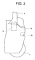
Fig. 3 is a fragmentary side view of a rear part of the battery forklift truck ofFig. 1 ; and -
Fig. 4 is a sectional view of the rear part ofFig. 3 . - The following will describe a preferred embodiment of the present invention with reference to
Figs. 1 through 4 . As shown inFigs. 1 and2 , an industrial vehicle according to the preferred embodiment is a three-wheel battery forklift truck. - Referring to
Figs. 1 and2 , the battery forklift truck includes avehicle body 1, a pair of left andright drive wheels 2 arranged at the front of thevehicle body 1 and a steeredwheel 3 arranged at the rear center of thevehicle body 1 and having two wheels. The battery forklift includes amast assembly 4 arranged forward of thevehicle body 1, an operator'sseat 5 on thevehicle body 1, abattery case 9 below the operator'sseat 5 for storing a battery, asteering wheel 6 forward of the operator'sseat 5 and front andrear pillars seat 5. - Referring to
Figs. 3 and4 , the battery forklift further includes acounterweight 10 having atop surface 10A and mounted on thevehicle body 1 at the rear end thereof. Acap 11 made of a resin material is detachably mounted to thecounterweight 10 at the top thereof so as to seal thecounterweight 10, as shown inFigs. 2 and4 . Removing thecap 11, thetop surface 10A of thecounterweight 10 is exposed outside, and thecounterweight 10 can be lifted using alift bar 10B. - As shown in
Fig. 4 , thetop surface 10A of thecounterweight 10 is slanted slightly downward toward the rear. This prevents any water flowing to thetop surface 10A of thecounterweight 10 through any clearance between thecap 11 and thecounterweight 10 from flowing to acontroller 13 as an electric component for controlling an operation of the buttery forklift truck located forward of thecounterweight 10. - The
counterweight 10 has ahole 10C formed therethrough extending linearly downwardly from the rear center of thetop surface 10A. Adrawbar 12 for engaging a hook is suspended in thehole 10C with the top portion thereof engaged with thetop surface 10A of thecounterweight 10. - A
space 10D is formed forward of thecounterweight 10, and thecontroller 13 is arranged forward of thespace 10D for controlling traveling and loading operations of the forklift truck and mounted on thevehicle body 1. In other words, thespace 10D is formed between thecounterweight 10 and thecontroller 13, or behind thecounterweight 10. Acover member 14 is provided above thecontroller 13 and, with thecover member 14 opened, thecontroller 13 is removable. - The rear end surface of the
counterweight 10 is formed extending substantially vertically. Thecounterweight 10 has arecess 20 extending substantially horizontally forwardly from the center of the rear end surface thereof. Thetop surface 20A of therecess 20 extends substantially horizontally. Thecounterweight 10 further has anair passage 30 formed therein extending upwardly toward thecontroller 13. Theair passage 30 has at the bottom end thereof an opening 30A formed at or opened on the center of thetop surface 20A of therecess 20 in the front-and-rear direction of thevehicle body 1, or theair passage 30 is formed extending forwardly upwardly from the opening 30A through thecounterweight 10. Therecess 20 has a closedend 20B at a position that is forward of the opening 30A. - The
hole 10C accommodating therein thedrawbar 12 is in communication with therecess 20 through the opening 30A of theair passage 30. Thedrawbar 12 is exposed outside in therecess 20 or accessible through therecess 20. - According to the battery forklift truck of the present invention, ambient air may flow through the
air passage 30 and be supplied to thecontroller 13, thereby cooling thecontroller 13 effectively. - The
air passage 30 which is formed extending upwardly makes it difficult for washing water W to flow through theair passage 30 if wash water W is sprayed from the rear of the forklift truck for washing. Thus, thecontroller 13 is protected from electrical leakage. - The
air passage 30 has at the bottom end thereof the opening 30A formed at thetop surface 20A of therecess 20, and therecess 20 has the closedend 20B at a position that is forward of the opening 30A. Thus, if water W is sprayed strongly against the rear of the forklift truck for washing, the sprayed water W strikes the closedend 20B of therecess 20, and therefore, hardly flows directly into theair passage 30 from the opening 30A. The water W sprayed directly against the closedend 20B is splashed and a part of the splashed water W may flow into theair passage 30 through the opening 30A, but flows down theair passage 30 due to gravity. Thus, the water W hardly passes through theentire air passage 30. - In the battery forklift truck according to the preferred embodiment of the present invention, the
drawbar 12 is arranged in thecounterweight 10, and therecess 20 is used as a space in which a hook (not shown) is engaged with thedrawbar 12. Thus, this structure of the battery forklift truck is utilized effectively. - As is apparent from the foregoing, electric leakage of the
controller 13 is prevented effectively without mounting a complete water-proofing mechanism on thecontroller 13, thereby reducing the manufacturing cost of the battery forklift truck. - In the battery forklift truck, the
recess 20 extends substantially horizontally, and the opening 30A of theair passage 30 is formed at thetop surface 20A of therecess 20 which is hardly visible from a person standing in a normal posture. That is, the battery forklift truck is advantageous in appearance in that the opening 30A of theair passage 30 for cooling thecontroller 13 is normally invisible. - The present invention is not limited to the above-described preferred embodiment, but it may be modified in various ways as exemplified below. Thought the present invention is applied to a three-wheel forklift truck in the preferred embodiment, the present invention is applicable to a four-wheel forklift truck.
- An industrial vehicle includes a vehicle body, an electric component and a counterweight. The electric component of the industrial vehicle is mounted on the vehicle body. The counterweight is mounted on the vehicle body at the rear end and rearward of the electric component. The counterweight has a recess formed extending forwardly of the vehicle body from the rear end surface of the counterweight and an air passage formed extending upwardly of the vehicle body toward the electric component from an opening formed at the top surface of the recess. The recess has a closed end at a position forward of the opening of the air passage.
Claims (10)
- An industrial vehicle comprising;
a vehicle body (1);
an electric component (13) of the industrial vehicle mounted on the vehicle body (1); and
a counterweight (10) mounted on the vehicle body (1) at the rear end and rearward of the electric component (13),
characterized in that the counterweight (10) has a recess (20) extending forwardly of the vehicle body (1) from the rear end surface of the counterweight (10) and an air passage (30) extending upwardly of the vehicle body (1) toward the electric component (13) from an opening (30A) formed at the top surface (20A) of the recess (20), and the recess (20) has a closed end (20B) at a position forward of the opening (30A) of the air passage (30). - The industrial vehicle according to claim 1, wherein the rear end surface of the counterweight (10) is formed extending vertically of the vehicle body (1), and the recess (20) of the counterweight (10) is formed extending horizontally of the vehicle body (1) from the center of the rear end surface of the counterweight (10).
- The industrial vehicle according to claim 1 or 2, wherein the top surface (20A) of the recess (20) is formed extending horizontally of the vehicle body (1), and the opening (30A) of the air passage (30) is formed at the middle of the top surface (20A) of the recess (20) in the front-and-rear direction of the vehicle body (1).
- The industrial vehicle according to any one of claims 1 through 3, wherein the air passage (30) is formed through the counterweight (10) extending forwardly of the vehicle body (1) from the opening (30A).
- The industrial vehicle according to any one of claims 1 through 4, wherein the top surface (10A) of the counterweight (10) is slanted downward of the vehicle body (1) toward the rear of the industrial vehicle.
- The industrial vehicle according to any one of claims 1 through 5, wherein a cap (11) is mounted to the counterweight (10) at the top of the counterweight (10) so as to seal the counterweight (10).
- The industrial vehicle according to any one of claims 1 through 6, wherein a space (10D) is formed between the electric component (13) and the counterweight (10).
- The industrial vehicle according to any one of claims 1 through 7, wherein a drawbar (12) for engaging a hook is arranged in the counterweight (10).
- The industrial vehicle according to claim 8, wherein a hole (10C) is formed through the counterweight (10) extending downwardly of the vehicle body (1) from the top surface (10A) of the counterweight (10), and the drawbar (12) is suspended in the hole (10C) with the top portion of the drawbar (12) engaged with the top surface (10A) of the counterweight (10).
- The industrial vehicle according to claim 9, wherein the hole (10C) is in communication with the recess (20) through the opening (30A) of the air passage (30).
Applications Claiming Priority (1)
| Application Number | Priority Date | Filing Date | Title |
|---|---|---|---|
| JP2008328546A JP4905446B2 (en) | 2008-12-24 | 2008-12-24 | Industrial vehicle |
Publications (2)
| Publication Number | Publication Date |
|---|---|
| EP2202195A2 true EP2202195A2 (en) | 2010-06-30 |
| EP2202195A3 EP2202195A3 (en) | 2010-08-04 |
Family
ID=42105842
Family Applications (1)
| Application Number | Title | Priority Date | Filing Date |
|---|---|---|---|
| EP09180546A Withdrawn EP2202195A3 (en) | 2008-12-24 | 2009-12-23 | Industrial vehicle |
Country Status (4)
| Country | Link |
|---|---|
| US (1) | US20100156079A1 (en) |
| EP (1) | EP2202195A3 (en) |
| JP (1) | JP4905446B2 (en) |
| CN (1) | CN101758773A (en) |
Families Citing this family (9)
| Publication number | Priority date | Publication date | Assignee | Title |
|---|---|---|---|---|
| CN102006489B (en) * | 2009-08-27 | 2015-02-04 | 晨星软件研发(深圳)有限公司 | Frame rate conversion apparatus for 3D display and associated method |
| US8616603B2 (en) | 2010-04-23 | 2013-12-31 | The Raymond Corporation | Operator ride enhancement system |
| JP2012106836A (en) * | 2010-11-17 | 2012-06-07 | Tcm Corp | Diesel particulate filter mounting structure for industrial vehicle |
| JP5649463B2 (en) * | 2011-01-14 | 2015-01-07 | 日立建機株式会社 | Construction machinery |
| US8919813B2 (en) | 2012-05-09 | 2014-12-30 | Schiller Grounds Care, Inc. | Tractor weight transfer mechanism |
| JP5692539B2 (en) * | 2012-09-18 | 2015-04-01 | 株式会社豊田自動織機 | Industrial vehicle |
| JP6194905B2 (en) * | 2015-02-04 | 2017-09-13 | 株式会社豊田自動織機 | Industrial vehicle |
| CN104735961B (en) * | 2015-03-12 | 2017-07-11 | 广东亿纬赛恩斯新能源系统有限公司 | The waterproof radiating structure of electric-controlled parts and the electric motor car with waterproof radiating structure |
| DE112015000056T5 (en) * | 2015-06-22 | 2016-01-14 | Komatsu Ltd. | Battery operated work vehicle and work vehicle battery |
Family Cites Families (11)
| Publication number | Priority date | Publication date | Assignee | Title |
|---|---|---|---|---|
| US3023024A (en) * | 1959-05-25 | 1962-02-27 | Clark Equipment Co | Removable weight for vehicle |
| DE2655441A1 (en) * | 1976-12-07 | 1978-06-08 | Linde Ag | LIFT LOADER WITH INTERNAL COMBUSTION ENGINE |
| JPS578491Y2 (en) * | 1977-04-19 | 1982-02-18 | ||
| US4093259A (en) * | 1977-05-02 | 1978-06-06 | Caterpillar Tractor Co. | Vehicle having resiliently mounted counterweight |
| JPS53143312A (en) * | 1977-05-20 | 1978-12-13 | Fuji Photo Film Co Ltd | Photographic film scanner |
| JPH01285424A (en) * | 1988-05-10 | 1989-11-16 | Toyota Autom Loom Works Ltd | Radiation structure of controller in industrial vehicle |
| JPH08282985A (en) * | 1995-04-19 | 1996-10-29 | Toyota Autom Loom Works Ltd | Counter weight supporting device for industrial vehicle |
| JPH09208193A (en) * | 1996-02-07 | 1997-08-12 | Nissan Motor Co Ltd | Seal structure of balance weight part in fork lift |
| JP4306939B2 (en) * | 2000-09-01 | 2009-08-05 | 株式会社小松製作所 | Air cleaner intake structure |
| US7849951B2 (en) * | 2007-02-28 | 2010-12-14 | Crown Equipment Corporation | Materials handling vehicle having at least one controller coupled to a front wall of a frame |
| JP2009274651A (en) * | 2008-05-16 | 2009-11-26 | Toyota Industries Corp | Hybrid industrial vehicle |
-
2008
- 2008-12-24 JP JP2008328546A patent/JP4905446B2/en not_active Expired - Fee Related
-
2009
- 2009-12-18 US US12/642,211 patent/US20100156079A1/en not_active Abandoned
- 2009-12-23 CN CN200910262082A patent/CN101758773A/en active Pending
- 2009-12-23 EP EP09180546A patent/EP2202195A3/en not_active Withdrawn
Non-Patent Citations (1)
| Title |
|---|
| None |
Also Published As
| Publication number | Publication date |
|---|---|
| JP4905446B2 (en) | 2012-03-28 |
| EP2202195A3 (en) | 2010-08-04 |
| JP2010149972A (en) | 2010-07-08 |
| CN101758773A (en) | 2010-06-30 |
| US20100156079A1 (en) | 2010-06-24 |
Similar Documents
| Publication | Publication Date | Title |
|---|---|---|
| EP2202195A2 (en) | Industrial vehicle | |
| US7455052B2 (en) | Fuel supply device | |
| JP2008062736A (en) | Four-wheel travel vehicle for irregular ground | |
| US9352799B2 (en) | Motorcycle | |
| EP2703265B1 (en) | Saddle type vehicle | |
| JP2008044551A (en) | Engine compartment cooling structure of off-road traveling four-wheel vehicle | |
| EP3006317B1 (en) | Article storage structure for automatic two-wheeled vehicles | |
| WO2011078236A1 (en) | Structure for reducing agent tank | |
| JP2006248490A (en) | Work vehicle tank structure | |
| JP2008149767A (en) | Tractor | |
| JP6016191B2 (en) | In-vehicle structure of vehicle battery pack | |
| CN102398650A (en) | Leg shield structure of saddle-ride-type vehicle | |
| JP4900737B2 (en) | Counterweight structure in a three-wheel forklift | |
| JP5205134B2 (en) | Work vehicle | |
| JP4686908B2 (en) | Battery powered vehicle | |
| JP2019011187A (en) | Battery-type forklift and battery attachment/detachment method of battery-type forklift | |
| JP2009091091A (en) | Battery hood of cargo handling vehicle | |
| JPH0624274A (en) | Industrial vehicle | |
| JP2006264940A (en) | Battery loading chamber of battery forklift | |
| JP5091772B2 (en) | Work vehicle | |
| JP4278045B2 (en) | Battery powered industrial vehicle | |
| JP4455845B2 (en) | Motorcycle fuel tank | |
| JP2010280449A (en) | Counter balance type forklift | |
| EP3778360B1 (en) | Usb terminal unit arrangement structure for saddle riding-type vehicle | |
| JP2541742Y2 (en) | Breather device |
Legal Events
| Date | Code | Title | Description |
|---|---|---|---|
| PUAI | Public reference made under article 153(3) epc to a published international application that has entered the european phase |
Free format text: ORIGINAL CODE: 0009012 |
|
| 17P | Request for examination filed |
Effective date: 20091223 |
|
| AK | Designated contracting states |
Kind code of ref document: A2 Designated state(s): AT BE BG CH CY CZ DE DK EE ES FI FR GB GR HR HU IE IS IT LI LT LU LV MC MK MT NL NO PL PT RO SE SI SK SM TR |
|
| PUAL | Search report despatched |
Free format text: ORIGINAL CODE: 0009013 |
|
| AK | Designated contracting states |
Kind code of ref document: A3 Designated state(s): AT BE BG CH CY CZ DE DK EE ES FI FR GB GR HR HU IE IS IT LI LT LU LV MC MK MT NL NO PL PT RO SE SI SK SM TR |
|
| RIC1 | Information provided on ipc code assigned before grant |
Ipc: B60K 13/06 20060101ALI20100630BHEP Ipc: B66F 9/075 20060101AFI20100427BHEP Ipc: B60D 1/145 20060101ALI20100630BHEP Ipc: B60D 1/00 20060101ALI20100630BHEP |
|
| RIC1 | Information provided on ipc code assigned before grant |
Ipc: B60K 11/06 20060101ALI20130911BHEP Ipc: B60D 1/145 20060101ALI20130911BHEP Ipc: B60D 1/00 20060101ALI20130911BHEP Ipc: B66F 9/075 20060101AFI20130911BHEP Ipc: B60K 13/06 20060101ALI20130911BHEP |
|
| GRAP | Despatch of communication of intention to grant a patent |
Free format text: ORIGINAL CODE: EPIDOSNIGR1 |
|
| INTG | Intention to grant announced |
Effective date: 20131018 |
|
| STAA | Information on the status of an ep patent application or granted ep patent |
Free format text: STATUS: THE APPLICATION IS DEEMED TO BE WITHDRAWN |
|
| 18D | Application deemed to be withdrawn |
Effective date: 20140301 |