EP2202051B1 - Infrarotschweißvorrichtung mit austauschbarem Schweissmodul - Google Patents
Infrarotschweißvorrichtung mit austauschbarem Schweissmodul Download PDFInfo
- Publication number
- EP2202051B1 EP2202051B1 EP20090180109 EP09180109A EP2202051B1 EP 2202051 B1 EP2202051 B1 EP 2202051B1 EP 20090180109 EP20090180109 EP 20090180109 EP 09180109 A EP09180109 A EP 09180109A EP 2202051 B1 EP2202051 B1 EP 2202051B1
- Authority
- EP
- European Patent Office
- Prior art keywords
- infrared
- machine frame
- welding
- workpieces
- tool holder
- Prior art date
- Legal status (The legal status is an assumption and is not a legal conclusion. Google has not performed a legal analysis and makes no representation as to the accuracy of the status listed.)
- Not-in-force
Links
Images

Classifications
-
- B—PERFORMING OPERATIONS; TRANSPORTING
- B29—WORKING OF PLASTICS; WORKING OF SUBSTANCES IN A PLASTIC STATE IN GENERAL
- B29C—SHAPING OR JOINING OF PLASTICS; SHAPING OF MATERIAL IN A PLASTIC STATE, NOT OTHERWISE PROVIDED FOR; AFTER-TREATMENT OF THE SHAPED PRODUCTS, e.g. REPAIRING
- B29C66/00—General aspects of processes or apparatus for joining preformed parts
- B29C66/80—General aspects of machine operations or constructions and parts thereof
-
- B—PERFORMING OPERATIONS; TRANSPORTING
- B29—WORKING OF PLASTICS; WORKING OF SUBSTANCES IN A PLASTIC STATE IN GENERAL
- B29C—SHAPING OR JOINING OF PLASTICS; SHAPING OF MATERIAL IN A PLASTIC STATE, NOT OTHERWISE PROVIDED FOR; AFTER-TREATMENT OF THE SHAPED PRODUCTS, e.g. REPAIRING
- B29C65/00—Joining or sealing of preformed parts, e.g. welding of plastics materials; Apparatus therefor
- B29C65/02—Joining or sealing of preformed parts, e.g. welding of plastics materials; Apparatus therefor by heating, with or without pressure
- B29C65/14—Joining or sealing of preformed parts, e.g. welding of plastics materials; Apparatus therefor by heating, with or without pressure using wave energy, i.e. electromagnetic radiation, or particle radiation
- B29C65/1403—Joining or sealing of preformed parts, e.g. welding of plastics materials; Apparatus therefor by heating, with or without pressure using wave energy, i.e. electromagnetic radiation, or particle radiation characterised by the type of electromagnetic or particle radiation
- B29C65/1412—Infrared [IR] radiation
-
- B—PERFORMING OPERATIONS; TRANSPORTING
- B29—WORKING OF PLASTICS; WORKING OF SUBSTANCES IN A PLASTIC STATE IN GENERAL
- B29C—SHAPING OR JOINING OF PLASTICS; SHAPING OF MATERIAL IN A PLASTIC STATE, NOT OTHERWISE PROVIDED FOR; AFTER-TREATMENT OF THE SHAPED PRODUCTS, e.g. REPAIRING
- B29C65/00—Joining or sealing of preformed parts, e.g. welding of plastics materials; Apparatus therefor
- B29C65/02—Joining or sealing of preformed parts, e.g. welding of plastics materials; Apparatus therefor by heating, with or without pressure
- B29C65/14—Joining or sealing of preformed parts, e.g. welding of plastics materials; Apparatus therefor by heating, with or without pressure using wave energy, i.e. electromagnetic radiation, or particle radiation
- B29C65/1429—Joining or sealing of preformed parts, e.g. welding of plastics materials; Apparatus therefor by heating, with or without pressure using wave energy, i.e. electromagnetic radiation, or particle radiation characterised by the way of heating the interface
- B29C65/1432—Joining or sealing of preformed parts, e.g. welding of plastics materials; Apparatus therefor by heating, with or without pressure using wave energy, i.e. electromagnetic radiation, or particle radiation characterised by the way of heating the interface direct heating of the surfaces to be joined
-
- B—PERFORMING OPERATIONS; TRANSPORTING
- B29—WORKING OF PLASTICS; WORKING OF SUBSTANCES IN A PLASTIC STATE IN GENERAL
- B29C—SHAPING OR JOINING OF PLASTICS; SHAPING OF MATERIAL IN A PLASTIC STATE, NOT OTHERWISE PROVIDED FOR; AFTER-TREATMENT OF THE SHAPED PRODUCTS, e.g. REPAIRING
- B29C65/00—Joining or sealing of preformed parts, e.g. welding of plastics materials; Apparatus therefor
- B29C65/78—Means for handling the parts to be joined, e.g. for making containers or hollow articles, e.g. means for handling sheets, plates, web-like materials, tubular articles, hollow articles or elements to be joined therewith; Means for discharging the joined articles from the joining apparatus
- B29C65/7841—Holding or clamping means for handling purposes
-
- B—PERFORMING OPERATIONS; TRANSPORTING
- B29—WORKING OF PLASTICS; WORKING OF SUBSTANCES IN A PLASTIC STATE IN GENERAL
- B29C—SHAPING OR JOINING OF PLASTICS; SHAPING OF MATERIAL IN A PLASTIC STATE, NOT OTHERWISE PROVIDED FOR; AFTER-TREATMENT OF THE SHAPED PRODUCTS, e.g. REPAIRING
- B29C66/00—General aspects of processes or apparatus for joining preformed parts
- B29C66/01—General aspects dealing with the joint area or with the area to be joined
- B29C66/05—Particular design of joint configurations
- B29C66/10—Particular design of joint configurations particular design of the joint cross-sections
- B29C66/11—Joint cross-sections comprising a single joint-segment, i.e. one of the parts to be joined comprising a single joint-segment in the joint cross-section
- B29C66/112—Single lapped joints
-
- B—PERFORMING OPERATIONS; TRANSPORTING
- B29—WORKING OF PLASTICS; WORKING OF SUBSTANCES IN A PLASTIC STATE IN GENERAL
- B29C—SHAPING OR JOINING OF PLASTICS; SHAPING OF MATERIAL IN A PLASTIC STATE, NOT OTHERWISE PROVIDED FOR; AFTER-TREATMENT OF THE SHAPED PRODUCTS, e.g. REPAIRING
- B29C66/00—General aspects of processes or apparatus for joining preformed parts
- B29C66/01—General aspects dealing with the joint area or with the area to be joined
- B29C66/05—Particular design of joint configurations
- B29C66/10—Particular design of joint configurations particular design of the joint cross-sections
- B29C66/13—Single flanged joints; Fin-type joints; Single hem joints; Edge joints; Interpenetrating fingered joints; Other specific particular designs of joint cross-sections not provided for in groups B29C66/11 - B29C66/12
- B29C66/131—Single flanged joints, i.e. one of the parts to be joined being rigid and flanged in the joint area
-
- B—PERFORMING OPERATIONS; TRANSPORTING
- B29—WORKING OF PLASTICS; WORKING OF SUBSTANCES IN A PLASTIC STATE IN GENERAL
- B29C—SHAPING OR JOINING OF PLASTICS; SHAPING OF MATERIAL IN A PLASTIC STATE, NOT OTHERWISE PROVIDED FOR; AFTER-TREATMENT OF THE SHAPED PRODUCTS, e.g. REPAIRING
- B29C66/00—General aspects of processes or apparatus for joining preformed parts
- B29C66/01—General aspects dealing with the joint area or with the area to be joined
- B29C66/05—Particular design of joint configurations
- B29C66/302—Particular design of joint configurations the area to be joined comprising melt initiators
- B29C66/3022—Particular design of joint configurations the area to be joined comprising melt initiators said melt initiators being integral with at least one of the parts to be joined
- B29C66/30223—Particular design of joint configurations the area to be joined comprising melt initiators said melt initiators being integral with at least one of the parts to be joined said melt initiators being rib-like
-
- B—PERFORMING OPERATIONS; TRANSPORTING
- B29—WORKING OF PLASTICS; WORKING OF SUBSTANCES IN A PLASTIC STATE IN GENERAL
- B29C—SHAPING OR JOINING OF PLASTICS; SHAPING OF MATERIAL IN A PLASTIC STATE, NOT OTHERWISE PROVIDED FOR; AFTER-TREATMENT OF THE SHAPED PRODUCTS, e.g. REPAIRING
- B29C66/00—General aspects of processes or apparatus for joining preformed parts
- B29C66/50—General aspects of joining tubular articles; General aspects of joining long products, i.e. bars or profiled elements; General aspects of joining single elements to tubular articles, hollow articles or bars; General aspects of joining several hollow-preforms to form hollow or tubular articles
- B29C66/51—Joining tubular articles, profiled elements or bars; Joining single elements to tubular articles, hollow articles or bars; Joining several hollow-preforms to form hollow or tubular articles
- B29C66/54—Joining several hollow-preforms, e.g. half-shells, to form hollow articles, e.g. for making balls, containers; Joining several hollow-preforms, e.g. half-cylinders, to form tubular articles
- B29C66/545—Joining several hollow-preforms, e.g. half-shells, to form hollow articles, e.g. for making balls, containers; Joining several hollow-preforms, e.g. half-cylinders, to form tubular articles one hollow-preform being placed inside the other
-
- B—PERFORMING OPERATIONS; TRANSPORTING
- B29—WORKING OF PLASTICS; WORKING OF SUBSTANCES IN A PLASTIC STATE IN GENERAL
- B29C—SHAPING OR JOINING OF PLASTICS; SHAPING OF MATERIAL IN A PLASTIC STATE, NOT OTHERWISE PROVIDED FOR; AFTER-TREATMENT OF THE SHAPED PRODUCTS, e.g. REPAIRING
- B29C66/00—General aspects of processes or apparatus for joining preformed parts
- B29C66/70—General aspects of processes or apparatus for joining preformed parts characterised by the composition, physical properties or the structure of the material of the parts to be joined; Joining with non-plastics material
- B29C66/73—General aspects of processes or apparatus for joining preformed parts characterised by the composition, physical properties or the structure of the material of the parts to be joined; Joining with non-plastics material characterised by the intensive physical properties of the material of the parts to be joined, by the optical properties of the material of the parts to be joined, by the extensive physical properties of the parts to be joined, by the state of the material of the parts to be joined or by the material of the parts to be joined being a thermoplastic or a thermoset
- B29C66/739—General aspects of processes or apparatus for joining preformed parts characterised by the composition, physical properties or the structure of the material of the parts to be joined; Joining with non-plastics material characterised by the intensive physical properties of the material of the parts to be joined, by the optical properties of the material of the parts to be joined, by the extensive physical properties of the parts to be joined, by the state of the material of the parts to be joined or by the material of the parts to be joined being a thermoplastic or a thermoset characterised by the material of the parts to be joined being a thermoplastic or a thermoset
- B29C66/7392—General aspects of processes or apparatus for joining preformed parts characterised by the composition, physical properties or the structure of the material of the parts to be joined; Joining with non-plastics material characterised by the intensive physical properties of the material of the parts to be joined, by the optical properties of the material of the parts to be joined, by the extensive physical properties of the parts to be joined, by the state of the material of the parts to be joined or by the material of the parts to be joined being a thermoplastic or a thermoset characterised by the material of the parts to be joined being a thermoplastic or a thermoset characterised by the material of at least one of the parts being a thermoplastic
- B29C66/73921—General aspects of processes or apparatus for joining preformed parts characterised by the composition, physical properties or the structure of the material of the parts to be joined; Joining with non-plastics material characterised by the intensive physical properties of the material of the parts to be joined, by the optical properties of the material of the parts to be joined, by the extensive physical properties of the parts to be joined, by the state of the material of the parts to be joined or by the material of the parts to be joined being a thermoplastic or a thermoset characterised by the material of the parts to be joined being a thermoplastic or a thermoset characterised by the material of at least one of the parts being a thermoplastic characterised by the materials of both parts being thermoplastics
-
- B—PERFORMING OPERATIONS; TRANSPORTING
- B29—WORKING OF PLASTICS; WORKING OF SUBSTANCES IN A PLASTIC STATE IN GENERAL
- B29C—SHAPING OR JOINING OF PLASTICS; SHAPING OF MATERIAL IN A PLASTIC STATE, NOT OTHERWISE PROVIDED FOR; AFTER-TREATMENT OF THE SHAPED PRODUCTS, e.g. REPAIRING
- B29C66/00—General aspects of processes or apparatus for joining preformed parts
- B29C66/80—General aspects of machine operations or constructions and parts thereof
- B29C66/81—General aspects of the pressing elements, i.e. the elements applying pressure on the parts to be joined in the area to be joined, e.g. the welding jaws or clamps
- B29C66/816—General aspects of the pressing elements, i.e. the elements applying pressure on the parts to be joined in the area to be joined, e.g. the welding jaws or clamps characterised by the mounting of the pressing elements, e.g. of the welding jaws or clamps
- B29C66/8167—Quick change joining tools or surfaces
-
- B—PERFORMING OPERATIONS; TRANSPORTING
- B29—WORKING OF PLASTICS; WORKING OF SUBSTANCES IN A PLASTIC STATE IN GENERAL
- B29C—SHAPING OR JOINING OF PLASTICS; SHAPING OF MATERIAL IN A PLASTIC STATE, NOT OTHERWISE PROVIDED FOR; AFTER-TREATMENT OF THE SHAPED PRODUCTS, e.g. REPAIRING
- B29C66/00—General aspects of processes or apparatus for joining preformed parts
- B29C66/80—General aspects of machine operations or constructions and parts thereof
- B29C66/84—Specific machine types or machines suitable for specific applications
- B29C66/841—Machines or tools adaptable for making articles of different dimensions or shapes or for making joints of different dimensions
-
- B—PERFORMING OPERATIONS; TRANSPORTING
- B29—WORKING OF PLASTICS; WORKING OF SUBSTANCES IN A PLASTIC STATE IN GENERAL
- B29C—SHAPING OR JOINING OF PLASTICS; SHAPING OF MATERIAL IN A PLASTIC STATE, NOT OTHERWISE PROVIDED FOR; AFTER-TREATMENT OF THE SHAPED PRODUCTS, e.g. REPAIRING
- B29C66/00—General aspects of processes or apparatus for joining preformed parts
- B29C66/90—Measuring or controlling the joining process
- B29C66/95—Measuring or controlling the joining process by measuring or controlling specific variables not covered by groups B29C66/91 - B29C66/94
-
- B—PERFORMING OPERATIONS; TRANSPORTING
- B29—WORKING OF PLASTICS; WORKING OF SUBSTANCES IN A PLASTIC STATE IN GENERAL
- B29C—SHAPING OR JOINING OF PLASTICS; SHAPING OF MATERIAL IN A PLASTIC STATE, NOT OTHERWISE PROVIDED FOR; AFTER-TREATMENT OF THE SHAPED PRODUCTS, e.g. REPAIRING
- B29C66/00—General aspects of processes or apparatus for joining preformed parts
- B29C66/90—Measuring or controlling the joining process
- B29C66/96—Measuring or controlling the joining process characterised by the method for implementing the controlling of the joining process
-
- B—PERFORMING OPERATIONS; TRANSPORTING
- B29—WORKING OF PLASTICS; WORKING OF SUBSTANCES IN A PLASTIC STATE IN GENERAL
- B29C—SHAPING OR JOINING OF PLASTICS; SHAPING OF MATERIAL IN A PLASTIC STATE, NOT OTHERWISE PROVIDED FOR; AFTER-TREATMENT OF THE SHAPED PRODUCTS, e.g. REPAIRING
- B29C66/00—General aspects of processes or apparatus for joining preformed parts
- B29C66/90—Measuring or controlling the joining process
- B29C66/96—Measuring or controlling the joining process characterised by the method for implementing the controlling of the joining process
- B29C66/967—Measuring or controlling the joining process characterised by the method for implementing the controlling of the joining process involving special data inputs or special data outputs, e.g. for monitoring purposes
- B29C66/9672—Measuring or controlling the joining process characterised by the method for implementing the controlling of the joining process involving special data inputs or special data outputs, e.g. for monitoring purposes involving special data inputs, e.g. involving barcodes, RFID tags
-
- B—PERFORMING OPERATIONS; TRANSPORTING
- B29—WORKING OF PLASTICS; WORKING OF SUBSTANCES IN A PLASTIC STATE IN GENERAL
- B29C—SHAPING OR JOINING OF PLASTICS; SHAPING OF MATERIAL IN A PLASTIC STATE, NOT OTHERWISE PROVIDED FOR; AFTER-TREATMENT OF THE SHAPED PRODUCTS, e.g. REPAIRING
- B29C35/00—Heating, cooling or curing, e.g. crosslinking or vulcanising; Apparatus therefor
- B29C35/02—Heating or curing, e.g. crosslinking or vulcanizing during moulding, e.g. in a mould
- B29C35/08—Heating or curing, e.g. crosslinking or vulcanizing during moulding, e.g. in a mould by wave energy or particle radiation
- B29C35/0805—Heating or curing, e.g. crosslinking or vulcanizing during moulding, e.g. in a mould by wave energy or particle radiation using electromagnetic radiation
- B29C2035/0822—Heating or curing, e.g. crosslinking or vulcanizing during moulding, e.g. in a mould by wave energy or particle radiation using electromagnetic radiation using IR radiation
-
- B—PERFORMING OPERATIONS; TRANSPORTING
- B29—WORKING OF PLASTICS; WORKING OF SUBSTANCES IN A PLASTIC STATE IN GENERAL
- B29C—SHAPING OR JOINING OF PLASTICS; SHAPING OF MATERIAL IN A PLASTIC STATE, NOT OTHERWISE PROVIDED FOR; AFTER-TREATMENT OF THE SHAPED PRODUCTS, e.g. REPAIRING
- B29C65/00—Joining or sealing of preformed parts, e.g. welding of plastics materials; Apparatus therefor
- B29C65/02—Joining or sealing of preformed parts, e.g. welding of plastics materials; Apparatus therefor by heating, with or without pressure
- B29C65/14—Joining or sealing of preformed parts, e.g. welding of plastics materials; Apparatus therefor by heating, with or without pressure using wave energy, i.e. electromagnetic radiation, or particle radiation
- B29C65/1496—Joining or sealing of preformed parts, e.g. welding of plastics materials; Apparatus therefor by heating, with or without pressure using wave energy, i.e. electromagnetic radiation, or particle radiation making use of masks
Definitions
- the invention relates to an infrared welding apparatus, comprising a machine frame with at least two workpiece carriers for two workpieces, the distance is variable, and at least one infrared radiator, which is fixed to a movable tool holder of the machine frame and introduced into the gap formed by the distance of the workpiece carrier of the workpieces and therefrom is removable.
- the InFrarotschw dervorraum arrives at the mutual welding of large-sized, thermoplastic plastic parts used, for example, in the manufacture of interior trim parts of motor vehicles used.
- An infrared welding device of the type mentioned is from the DE 20 2006 003 323 U1 known.
- the plastic parts produced in a separate step by injection molding, blow molding, stamping, thermoforming or similar are inserted into the workpiece holders and positioned in relation to the one or more infrared radiators so that the partial surfaces to be welded soften until they reach a molten state.
- the at least one infrared radiator is removed from the intermediate space between the partial surfaces and the partial surfaces are fused and connected by mutual approach and subsequent compression into one another.
- the compound is stable after the subsequent cooling, so that the finished connected plastic parts can be removed and fed to their use.
- the US 2003/0221783 A1 discloses an infrared welding device according to the preamble of claim 1.
- the web site http://www.forwardtech.com/plastic-assembly/infrared-welders/aboutinfrared-welding discloses an infrared welding apparatus comprising two workpiece carriers and a tool holder that are portable together.
- the tool of this infrared welding device is exchangeable by means of a quick-change mechanism.
- the GB 2 345 459 A discloses a welding apparatus having upper and lower jigs and a standby hot plate which can be slid between the jigs.
- the invention is based on the object to further develop such an infrared welding device such that it significantly reduces the time required for a possible workpiece change both in terms of conversion from also with regard to the control of the movements and the operation of the infrared radiator.
- the inventive infrared welding device comprises a machine frame with at least two workpiece carriers whose spacing varies, and at least one infrared radiator which is fixed to a movable tool holder of the machine frame and can be introduced into the intermediate space of the workpieces formed by the spacing of the workpiece carriers ,
- the distance between the workpiece carrier and thus the workpieces of each other and the relative assignment of the tool holder can be changed by a program control and the workpiece carrier and the tool holder can be moved together to a transportable as a closed unit welding module and connectable with quick couplings with the machine frame.
- a possible tool change can be achieved in a few minutes.
- the workpiece carrier and / or the tool holder can be provided with spacers and be immovably supported by the spacers 5 within the welding module 7.
- the self-contained welding module can therefore be moved as a self-contained and intrinsically stable unit without the risk of unintentional damage to the infrared radiator or consists.
- the infrared radiators are during storage and transport rather through the workpiece carrier specially protected, without the need for extra effort. It is therefore possible to use any and also particularly mechanically sensitive infrared radiators, for example quartz radiators and / or thermal foils.
- the individual parts are positioned so that they can be brought into direct engagement without extensive manipulation with the respective quick couplings of the machine frame. This speeds up a tool change.
- the workpieces to be welded are additionally located between the workpiece carriers and the tool holder or the infrared radiator attached thereto, which precludes the spacers from coming into contact with the system during normal use of the welding module and hindering the achievement of a correct welding process.
- the compression necessary to achieve a good welding of the parts to be joined can therefore be effected without the spacers getting into mutual contact with each other.
- the program control can be carried out in the simplest case by a following step control, which can also be designed as a pneumatic control. It may comprise an additional module for switching on and off the at least one infrared radiator. If multiple infrared radiators are provided to create different welding zones, it may be useful to use different size infrared radiators. Nevertheless, in order to obtain a good welding result when simultaneously joining the workpieces in all welding zones, it is necessary to achieve the ideal welding temperatures in all welding zones at the same time. The infrared radiators are activated accordingly. You can not in be heated areas to be covered by panels to produce separate welding zones with only one infrared radiator.
- the infrared radiators can also be directed in conjunction with mirrors on difficult to reach places of the workpieces. Furthermore, infrared radiators can be used, which heat the opposite welding zones with only one heat source.
- the distances of the workpiece holder are accordingly adjusted by means of the controller.
- the tool change can be further accelerated if the program control includes an additional locking module for the quick couplings. This results in the additional advantage that a start-up is particularly easy to block, if not all quick-release couplings are operated properly. Inadvertent damage to the infrared welding device is thereby prevented.
- the welding module can be inserted from behind into the machine frame and can only be connected to the machine frame 1 by means of laterally attached quick-release couplings.
- the feeding of the infrared welding device from the front with workpieces is thus not required for a tool change, which makes it possible to roll conveyors or the like on the front side of the infrared welding device. provided to facilitate the supply and removal of the workpieces.
- the welding module can be suitably charged only from the direction of the front side of the machine frame with the workpieces to be welded, wherein the welded workpieces are removable only in the direction of the front.
- At least one workpiece carrier is pivotally connected to the machine frame.
- the mutual, temporary connection of the workpieces with the workpiece adapters can be carried out by suction cups and the positioning of the workpieces can be substantially facilitated if an overhead feed is avoided.
- At least the upper workpiece holder should therefore be swivelable at least in a vertical position, even better in an at least approximately table-like position.
- the tool holder in the machine frame is displaceable or pivotable relative to the workpiece carriers.
- the machine frame can be assigned a memory for at least two welding modules, with means being provided for alternatively inserting the welding modules received in the memory into the machine frame and engaging them with the quick-release couplings.
- the memory may be formed by a ring memory or a high-bay warehouse.
- a tool change can also be fully automatic. At least in the machine frame to skids and / or roller conveyors may be provided for facilitated introduction and removal of the welding module.
- the program control is contained in a computer, if the identifiers are identifiable by sensors of the machine frame, the workpiece carrier and / or the tool holder, if the sensors are signal conductively connected to the computer and if the workpiece carrier in that the tool holder and the at least one infrared radiator 3 are moved and / or actuated by the computer as a function of the respective identification mark.
- Fig. 1 shows an exemplary embodiment of the infrared welding device in a front view. It comprises a machine frame 1 with a retracted therein welding module 7 of two workpiece carriers 2 for two workpieces 10.1, 10.2, whose distance is variable, and two infrared radiators 3, which are fixed to a movable tool holder 4 of the machine frame 1 and in by the distance of the workpiece carrier 2 formed gap of the workpieces 10.1, 10.2 can be introduced.
- the infrared radiator 3 consist of high-performance quartz radiators, which are effective in the short-wave infrared range and cause rapid heating of the workpieces to be welded 10.1, 10.2.
- the workpiece carrier 2 and the tool holder 4 are connected by quick couplings 6 independently of each other with the machine frame 1 and displaceable relative to each other in the vertical and horizontal directions.
- the workpiece carrier 2 and the tool holder 4 are vertically and / or horizontally so far away from each other and possibly pivoted that the workpieces 10.1, 10.2 ergonomically inserted and removed comfortably. This is in Fig. 3 indicated in the side view.
- the infrared radiators 3 are removed with the aid of the tool carrier 4 from the intermediate space of the workpieces 10.1, 10.2 and the workpieces 10.1, 10.2 pressed together with a precisely predetermined force with mutual approach of the workpiece carrier 2 in the region of the zones to be welded.
- the material of the workpieces 10.1, 10.2 flows into each other in the softened zones, resulting in a mutual weld connection of the workpieces 10.1, 10.2. This is mechanically strong and stable after the subsequent cooling of the material.
- the two workpieces 10.1, 10.2 are then firmly connected to a unit.
- the infrared radiators are used very selectively and only thermally soften the zones to be welded. This is achieved by a targeted selection, positioning and optionally by covering the workpieces 10.1, 10.2 and / or the infrared radiator by masks in areas of the workpieces 10.1, 10.2, which are not to heat and to weld. Damage to the workpieces 10.1, 10.2 is therefore not to be feared in such areas by the welding. They can therefore be designed as desired and there also be equipped with heat-sensitive additional parts.
- the individual process steps at least the heating of the welding zones of the workpieces 10.1, 10.2 and their compression must be exactly matched to each other and carried out quickly.
- the distance of the workpiece carrier 2 from each other and the relative assignment of the tool holder 4 are for this purpose changed by a program control and the workpiece carrier 2 and the tool holder 4 are movable together to a transportable as a closed unit welding module 7, as in Fig. 2 shown.
- the workpiece carrier 2 and the tool holder 4 are connected by quick couplings 6 to the machine frame 1.
- the quick couplings 6 contain, in addition to the mechanical connections of the workpiece carriers 2 and the tool holder 4, the electrical connections of the infrared radiators 3.
- the workpiece carrier 2 and the tool holder 4 are provided with spacers 5 and immovably supported within the welding module 7 by the spacers 5 on each other.
- the welding module 7 can be manipulated as a closed unit, transportable and storable.
- the machine frame 1 comprises a program control with an additional module for the correct switching on and connecting the two infrared radiators 3. This makes it possible to heat differently activatable welding zones so that they reach the same time the optimum welding temperature as a prerequisite that after removal of the Infrared radiator 3 and the compression of the welding zones results in an optimal mutual welding in all sub-areas, ie an optimal merging into one another merging of the two materials to be welded workpieces 10.1, 10.2 in the zones to be welded.
- the program control includes an additional locking module for the quick couplings 6. Before a correct locking of all quick couplings 6 commissioning and damage to the infrared welding device is therefore excluded.
- the welding module 7 can only be inserted into the machine frame 1 from behind and can only be connected to the machine frame 1 by means of laterally attached quick-release couplings 6. This facilitates a quick tool change.
- the tool holder 4 is slidably mounted in the machine frame 1 relative to the workpiece carriers 2 in order not to hinder the insertion or removal of workpieces.
- the machine frame 1 is at the back of a memory 8 for at least two welding modules 7, assigned here for five welding modules 7, wherein means are provided which allow the recorded in the memory 8 welding modules 7 alternatively introduce into the machine frame 1 and with the quick couplings 6 in To interfere.
- the memory 8 is designed in the manner of a high-bay warehouse and comprises a plurality of superimposed storage bins on which a plurality of welding modules 7 can be parked independently of each other, which are directly available as needed in single access and transferred into the machine frame 1 can be. To facilitate this, skids for the welding module 7 are provided in the machine frame 1 and the accumulator 8.
- the high-bay warehouse is vertically displaceable in order to position each storage space as needed immediately behind the rear insertion opening of the machine frame 1 can. Alternatively, it is possible to provide a gap between the high-bay warehouse and the machine frame 1, in which a tool manipulator, not shown, is arranged. Such manipulators are known from high-bay warehouse technology.
- the welding module 7 can be loaded only from the direction of the front side 9 of the machine frame 1 with the workpieces 10.1, 10.2 to be welded. In the same direction, the welded workpieces 10 can be removed only in the direction of the front side 9.
- the welding modules 7 carry identically affixed identification marks, wherein the identification marks can be input manually into the program control and wherein the workpiece carriers 2, the tool holder 4 and the two infrared radiators 3 can be actuated by the program control as a function of the respective identification mark. This saves after a tool change separate adjustments and it is particularly unnecessary to entrust specialized personnel with the loading, commissioning or a tool change.
- the program control is presently contained in a computer, not shown, wherein the identification marks are identifiable by sensors of the machine frame 1, the workpiece carrier 2 and / or the tool holder 4, wherein the sensors are connected signal conducting to the computer and wherein the workpiece carrier 2, the tool holder and the two infrared radiators 3 are actuated by the computer depending on the respective identification mark.
- a misoperation is completely excluded.
- a particularly certainly identifiable identification mark consists of a bar code, to which the invention is naturally not specified.
- Fig. 4 shows two exemplary workpieces to be welded
- Fig. 4 two exemplary workpieces to be welded in a cross-sectional representation. They are large-size injection-molded parts which are intended for use as a carrier in a dashboard for a motor vehicle and which are to be welded only in a partial area and then enclose a large-sized cavity.
- the one of the workpieces 10.1 is provided with a vertically projecting to the welding plane, integrally molded bar to have a sufficiently large volume of weldable mass in the weld zone available, which can be thermally softened, without compromising the stability and Dimensional stability of the workpiece 10.1 per se to endanger.
- At least the strip of one workpiece 10.1 and its opposite welding zone of the other workpiece 10.2 are heated parallel to each other by infrared rays to welding temperature, in which the tool holder 4 with the attached and effective in both directions infrared emitters 3 temporarily into the gap of the workpieces to be thrown 10.1 , 10.2 and activated so that both workpieces simultaneously reach the optimum welding temperature.
- the tool carrier 4 is quickly moved out of the intermediate space in the transverse direction and the two workpieces 10.1, 10.2 are pressed together in the area of the zones to be spliced and the weld zone is solidified by cooling.
- Fig. 5 shows the workpieces 10.1, 10.2 according to Fig. 4 following the mutual welding. They are united into a single molded part 10, which is held together only in the area of a welding zone and can be supplied for further use. Of course, several welding zones can be provided, which connect the workpieces.
Landscapes
- Engineering & Computer Science (AREA)
- Mechanical Engineering (AREA)
- Physics & Mathematics (AREA)
- Electromagnetism (AREA)
- Health & Medical Sciences (AREA)
- Toxicology (AREA)
- Lining Or Joining Of Plastics Or The Like (AREA)
Description
- Die Erfindung betrifft eine Infrarotschweißvorrichtung, umfassend ein Maschinengestell mit zumindest zwei Werkstückträgern für zwei Werkstücke, deren Abstand veränderlich ist, sowie zumindest einem Infrarotstrahler, der an einem beweglichen Werkzeughalter des Maschinengestells festgelegt und in den durch den Abstand der Werkstückträger gebildeten Zwischenraum der Werkstücke einbringbar und daraus entfernbar ist. Die InFrarotschweißvorrichtung gelangt bei der gegenseitigen Verschweißung von großformatigen, thermoplastischen Kunststoffteilen zur Anwendung, die beispielsweise bei der Herstellung von Innraumverkleidungsteilen von Kraftfahrzeugen zur Anwendung gelangen.
- Eine Infrarotschweißvorrichtung der eingangs genannten Art ist aus der
DE 20 2006 003 323 U1 bekannt. Dabei werden die in einem gesonderten Arbeitsschritt durch Spritzgießen, Blasformen, Stanzen, Warmformen oder ähnlich hergestellten Kunststoffteile in die Werkstückaufnahmen eingelegt und in Bezug auf den oder die Infrarotstrahler so positioniert, dass die zu verschweißenden Teilflächen bis zum Erreichen eines schmelzflüssigen Zustandes erweichen. Im Anschluss daran wird der mindestens eine Infrarotstrahler aus dem Zwischenraum zwischen den Teilflächen entfernt und die Teilflächen werden durch gegenseitige Annäherung und nachfolgende Verpressung ineinanderübergehend verschmolzen und verbunden. Die Verbindung ist nach der sich anschließenden Abkühlung beständig, so dass die fertig verbundenen Kunststoffteile entnommen und Ihrer Verwendung zugeführt werden können. - Die Erzielung eines guten Arbeitsergebnisses setzt eine exakte Betätigung des Infrarotstrahlers voraus, was mit einem erheblichen Zeitaufwand bezüglich der Ansteuerung verbunden ist. Auch sind die Umrüstarbeiten in Bezug auf eine Verschweißung abweichend gestalteter Werkstücke sehr aufwendig, weil die Werkstückhalter und der Werkzeugzeughatter mit dem Maschinengestell verschraubt und speziell angepasst sind. Es ist daher erforderlich, in eine Umrüstung auf ein anders Werkstück jeweils einen erheblichen Zeitaufwand zu investieren.
- Die
US 2003/0221783 A1 offenbart eine Infrarotschweißvorrichtung gemäß dem Oberbegriff des Anspruchs 1. - Die Internetseite http://www.forwardtech.com/plastic-assembly/infrared-welders/aboutinfrared-welding offenbart eine Infrarotschweißvorrichtung umfassend zwei Werkstückträger und ein Werkzeughalter, die zusammen transportabel sind. Das Werkzeug dieser Infrarotschweißvorrichtung ist mittels eines Schnellwechsel-Mechanismus austauschbar.
- Die
GB 2 345 459 A - Der Erfindung liegt die Aufgabe zu Grunde, eine solche Infrarotschweißvorrichtung derart weiter zu entwickeln, dass sie der Zeitaufwand bei einem eventuellen Werkstückwechsel sowohl hinsichtlich der Umrüstung aus auch hinsichtlich der Ansteuerung der Bewegungen und der Betätigung des Infrarotstrahlers erheblich reduziert.
- Diese Aufgabe wird erfindungsgemäß mit den kennzeichnenden Merkmalen von Anspruch 1 gelöst. Auf vorteilhafte Ausgestaltungen nehmen die Unteransprüche Bezug.
- Die erfindungsgemäße Infrarotschweißvorrichtung umfasst zur Lösung dieser Aufgabe ein Maschinengestell mit zumindest zwei Werkstückträgern für zwei Werkstücke, deren Abstand veränderlich ist, sowie zumindest einem Infrarotstrahler, der an einem beweglichen Werkzeughalter des Maschinengestells festgelegt und in den durch den Abstand der Werkstückträger gebildeten Zwischenraum der Werkstücke einbringbar ist. Der Abstand der Werkstückträger und damit der Werkstücke von einander und die relative Zuordnung des Werkzeughalters sind durch eine Programmsteuerung veränderbar und die Werkstückträger und der Werkzeughalter sind zu einem als geschlosssene Baueinheit transportablen Schweißmodul zusammenfahrbar und durch Schnellkupplungen mit dem Maschinengestell verbindbar. Ein eventueller Werkzeugwechsel lässt sich dadurch in wenigen Minuten bewirken.
- Die Werkstückträger und/oder der Werkzeughalter können mit Abstandhaltern versehen und innerhalb des Schweißmoduls 7 durch die Abstandhalter 5 unverrückbar aufeinander abgestützt sein. Der in sich geschlossene Schweißmodul kann daher als in sich geschlossene und eigenstabile Baueinheit verlagert werden, ohne dass die Gefahr einer unbeabsichtigten Beschädigung des oder der Infrarotstrahler besteht. Die Infrarotstrahler werden während der Lagerung und des Transports vielmehr durch die Werkstückträger besonders geschützt, ohne dass es hierfür eines zusätzlichen Aufwands bedarf. Es können daher beliebige und auch mechanisch besonders empfindliche Infrarotstrahler verwendet werden, beispielsweise Quarzstrahler und / oder Wärmefolien.
- Innerhalb des zusammengefahrenen, transportfähigen Schweißmoduls sind die einzelnen Teile so positioniert, dass sie ohne aufwendige Manipulationen mit den jeweiligen Schnellkupplungen des Maschinengestells in direkten Eingriff gebracht werden können. Dies beschleunigt einen Werkzeugwechsel.
- Während der normalen Verwendung befinden sich zwischen den Werkstückträgern und dem Werkzeughalter bzw. dem daran festgelegten Infrarotstrahler zusätzlich die zu verschweißenden Werkstücke, was es ausschließt, dass die Abstandhalter während der normalen Verwendung des Schweißmoduls in eine Anlageberührung gelangen und die Erzielung eines korrekten Schweißprozesses behindern können. Die zur Erzielung einer guten Verschweißung der zu verbindenden Teile notwendige Verpressung kann daher bewirkt werden, ohne dass die Abstandhalter in eine gegenseitige Anlageberührung gelangen.
- Die Programmsteuerung kann im einfachsten Fall durch eine Folgeschrittsteuerung erfolgen, die auch als pneumatische Steuerung ausgelegt sein kann. Sie kann einen zusätzlichen Modul zur Ein- und Ausschaltung des mindestens einen Infrarotstrahlers umfassen. Wenn mehrere Infrarotstrahler zur Erzeugung von unterschiedlichen Schweißzonen vorgesehen sind, kann es sachdienlich sein, Infrarotstrahler mit unterschiedlicher Leistung zu verwenden. Um dennoch beim gleichzeitigen Zusammenfügen der Werkstücke in allen Schweißzonen ein gutes Schweißergebnis zu erhalten, ist es dabei notwendig, die idealen Schweißtemperaturen in allen Schweißzonen gleichzeitig zu erzielen. Die Infrarotstrahler werden demgemäss aktiviert. Sie können in nicht zu erwärmenden Bereichen durch Blenden abgedeckt sein, um von einander getrennte Schweißzonen mit nur einem Infrarotstrahler zu erzeugen.
- Die Infrarotstrahler können ferner in Verbindung mit Spiegeln auch auf schwierig zu erreichende Stellen der Werkstücke gerichtet sein. Ferner können Infrarotstrahler verwendet werden, die die einander gegenüberliegenden Schweißzonen mit nur einer Wärmquelle erwärmen.
- Je nach Art des Infrarotstrahlers kann es wichtig sein, ihn während seiner Aktivierung in einen bestimmten Abstand von der zu erwärmenden Zone anzuordnen. Die Abstände der Werkstückhalter werden demgemäss mit Hilfe der Steuerung justiert.
- Der Werkzeugwechsel lässt sich weiter beschleunigen, wenn die Programmsteuerung einen zusätzlichen Verriegelungsmodul für die Schnellkupplungen umfasst. Dabei ergibt sich der zusätzliche Vorteil, dass eine Inbetriebnahme besonders einfach blockierbar ist, wenn nicht alle Schnellkupplungen ordnungsgemäß betätigt sind. Einer unbeabsichtigten Beschädigung der Infrarotschweißvorrichtung wird dadurch vorgebeugt.
- Als besonders vorteilhaft hat es sich erwiesen, wenn der Schweißmodul von hinten in das Maschinengestell einführbar und nur durch seitlich angebrachte Schnellkupplungen mit dem Maschinengestell 1 verbindbar ist. Die zur Beschickung der Infrarotschweißvorrichtung von vorn mit Werkstücken wird dadurch für einen Werkzeugwechsel nicht benötigt, was es ermöglicht, an der Vorderseite der Infrarotschweißvorrichtung Rollenbahnen o.ä. vorzusehen, um die Zu- und Abführung der Werkstücke zu erleichtern. Der Schweißmodul ist demgemäss zweckmäßig nur aus der Richtung der Vorderseite des Maschinengestells mit den zu verschweißenden Werkstücken beschickbar, wobei die verschweißten Werkstücke nur in Richtung der Vorderseite entnehmbar sind.
- Aus ergonomischen Gründen hat es sich als zweckmäßig erwiesen, wenn zumindest ein Werkstückträger schwenkbar mit dem Maschinengestell verbindbar ist. Die gegenseitige, temporäre Verbindung der Werkstücke mit den Werkstückhaftern kann durch Saugnäpfe erfolgen und die Positionierung der Werkstücke lässt sich wesentlich erleichtern, wenn eine Zuführung über Kopf vermieden wird. Zumindest der obere Werkstückhalter sollte daher zumindest in eine senkrechte Lage, noch besser in eine zumindest angenähert tischartige Lage umschwenkbar sein.
- Um das Einlegen und Entnehmen der Werkstücke nicht zu behindern, kann es ferner zweckmäßig sein, wenn der Werkzeughalter in dem Maschinengestell relativ zu den Werkstückträgern verschiebbar oder schwenkbar ist.
- Um den Werkzeugwechsel weiter zu beschleunigen kann dem Maschinengestell rückseitig ein Speicher für zumindest zwei Schweißmodule zugeordnet sein, wobei Mittel vorgesehen sind, die es ermöglichen, die in dem Speicher aufgenommenen Schweißmodule alternativ in das Maschinengestell einzuführen und mit den Schnellkupplungen in Eingriff zu bringen. Der Speicher kann durch einen Ringspeicher oder ein Hochregallager gebildet sein. Ein Werkzeugwechsel kann dabei auch vollautomatisch erfolgen. Zumindest in dem Maschinengestell können dazu Gleitkufen und / oder Rollenbahnen zur erleichterten Einführung und Entnahme des Schweißmoduls vorgesehen sein.
- Wenn zumindest zwei Schweißmodule vorgesehen sind, die übereinstimmend angebrachte Identifizierungskennzeichen tragen, besteht ferner die Möglichkeit, die Identifzierungskennzeichen in die Programmsteuerung eingebbar zu gestalten, wobei die Werkstückträger, der Werkzeughalter und der mindestens eine Infrarotstrahler in Abhängigkeit von dem jeweiligen ldentifizierungskennzeichen durch die Programmsteuerung betätigbar sind. Im Anschluss an einen Werkzeugwechsel ist dadurch eine erneute Justierung der Werkzeugbewegungen und der Einschaltzeiten und -zeitpunkte des mindestens einen Infrarotstrahlers entbehrlich und es kann unter Verwendung der bereits vorab hierzu gespeicherten Daten sofort wieder mit dem echten Produktionsbetrieb begonnen werden.
- Zu solchen Zwecken hat es sich als zweckmäßig erwiesen, wenn die Programmsteuerung in einem Computer enthalten ist, wenn die Identifizierungskennzeichen durch Sensoren des Maschinengestells, der Werkstückträger und / oder des Werkzeughalters identifizierbar sind, wenn die Sensoren signalleitend mit dem Computer verbunden sind und wenn die Werkstückträger, der Werkzeughalter und der mindestens eine Infrarotstrahler 3 in Abhängigkeit von dem jeweiligen Identifizierungskennzeichen durch den Computer bewegt und /oder betätigbar sind.
- Die Erfindung wird nachfolgend an Hand der Zeichnung weiter verdeutlicht. Es zeigen:
-
Fig. 1 eine beispielhafte Ausführung der Infrarotschweißvorrichtung in einer Ansicht von vorn. -
Fig. 2 einen zu einer Transporteinheit zusammengefahrenen Infrarotschweißmodul in einer Ansicht von vorn -
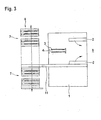
Fig. 3 Eine Infrarotschweißvorrichtung von der Seite mit einem an der Rückseite angeordneten Speicher für mehrere Infrarotschweißmodule -
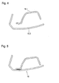
Fig. 4 zwei zu verschweißende, beispielhafte Werkstücke in quergeschnittener Darstellung -
Fig. 5 die Werkstücke gemäßFig. 4 in Anschluss an die gegenseitige Verschweißung - Übereinstimmende Bezugszeichen bezeichnen in den verschiedenen Zeichnungen identische Teile.
-
Fig. 1 zeigt eine beispielhafte Ausführung der Infrarotschweißvorrichtung in einer Ansicht von vorn. Sie umfasst ein Maschinengestell 1 mit einem darin eingefahrenen Schweißmodul 7 aus zwei Werkstückträgern 2 für zwei Werkstücke 10.1, 10.2, deren Abstand veränderlich ist, sowie zwei Infrarotstrahlern 3, die an einem beweglichen Werkzeughalter 4 des Maschinengestells 1 festgelegt und in den durch den Abstand der Werkstückträger 2 gebildeten Zwischenraum der Werkstücke 10.1, 10.2 einbringbar ist. Die Infrarotstrahler 3 bestehen aus Hochleistungsquarzstrahlern, die im kurzwelligen Infrarotbereich wirksam sind und eine schnelle Aufheizung der zu verschweißenden Werkstücke 10.1, 10.2 bewirken. Hierfür nicht benötigte Bereiche der Infrarotstrahler 3 sind gegenüber den Werkstücken10.1, 10.2 durch nicht dargestellte Blenden abgedeckt. Die Werkstückträger 2 und der Werkzeughalter 4 sind durch Schnellkupplungen 6 unabhängig voneinander mit dem Maschinengestell 1 verbunden und relativ zu einander in vertikaler und horizontaler Richtung verschiebbar. Zum Einlegen der zu verschweißenden Werkstücke 10.1, 10.2 werden die Werkstückträger 2 und der Werkzeughalter 4 vertikal und / oder horizontal so weit voneinander entfernt und eventuell verschwenkt, dass die Werkstücke 10.1, 10.2 ergonomisch bequem eingelegt und entnommen werden können. Dies ist inFig. 3 in der Seitenansicht angedeutet. Zur Durchführung einer Verschweißung der Werkstücke 10.1, 10.2 werden sie in einem exakt vorherbestimmten Abstand so angeordnet, dass die Infrarotstrahler eine hinreichende, thermische Erweichung des Werkstoffes der zu verweißenden Werkstücke 10.1, 10.2 in den zu verschweißenden Teilzonen bewirken. Ist der richtige Erweichungszustand erreicht, bei dem es sich gewöhnlich um einen schmelzflüssigen Zustand der Oberfläche der Werkstücke 10.1, 10.2 im Bereich der zu verschweißenden Zonen handelt, dann werden die Infrarotstrahler 3 mit Hilfe des Werkzeugträgers 4 aus dem Zwischenraum der Werkstücke 10.1, 10.2 entfernt und die Werkstücke 10.1, 10.2 mit einer exakt vorherbestimmten Kraft unter gegenseitiger Annäherung der Werkstückträger 2 im Bereich der zu verschweißenden Zonen miteinander verpresst. Der Werkstoff der Werkstücke 10.1, 10.2 fließt dabei in den erweichten Zonen ineinander über, wobei sich eine gegenseitige Schweißverbindung der Werkstücke 10.1, 10.2 ergibt. Diese ist nach der sich anschließenden Abkühlung des Werkstoffes mechanisch fest und stabil. Die beiden Werkstücke 10.1, 10.2 sind dadurch anschließend zu einer Einheit fest verbunden. - Von wesentlicher Bedeutung ist es für die praktische Anwendung, dass die Infrarotstrahler sehr gezielt eingesetzt werden und nur die zu verschweißenden Zonen thermisch erweichen. Dies gelingt durch eine gezielte Auswahl, Positionierung und gegebenenfalls durch eine Abdeckung der Werkstücke 10.1, 10.2 und/oder der Infrarotstrahler durch Masken in Bereichen der Werkstücke 10.1, 10.2 , die nicht zu erwärmen und zu verschweißen sind. Eine Beschädigung der Werkstücke 10.1, 10.2 ist daher in solchen Bereichen nicht durch die Verschweißung zu befürchten. Sie können demgemäss beliebig gestaltet und dort auch mit wärmeempfindlichen Zusatzteilen ausgestattet sein.
- Um eine gute Verschweißung der Werkstücke 10.1, 10.2 zu erzielen, müssen die einzelnen Prozessschritte zumindest der Erwärmung der Schweißzonen der Werkstücke 10.1, 10.2 und deren Zusammenpressung exakt aufeinander abgestimmt sein und zügig durchgeführt werden. Der Abstand der Werkstückträger 2 von einander und die relative Zuordnung des Werkzeughalters 4 sind zu diesem Zweck durch eine Programmsteuerung veränderbar und die Werkstückträger 2 und der Werkzeughalter 4 sind zu einem als geschlossene Baueinheit transportablen Schweißmodul 7 zusammenfahrbar, wie in
Fig. 2 gezeigt. Die Werkstückträger 2 und der Werkzeughalter 4 sind durch Schnellkupplungen 6 mit dem Maschinengestell 1 verbindbar. Die Schnellkupplungen 6 enthalten neben den mechanischen Anschlüssen der Werkstückträger 2 und des Werkzeughalters 4 die elektrischen Anschlüsse der Infrarotstrahler 3. - Die Werkstückträger 2 und der Werkzeughalter 4 sind mit Abstandhaltern 5 versehen und innerhalb des Schweißmoduls 7 durch die Abstandhalter 5 unverrückbar aufeinander abgestützt. Der Schweißmodul 7 ist dadurch als geschlossene Einheit manipulierbar, transport- und lagerfähig.
- Das Maschinengestell 1 umfasst eine Programmsteuerung mit einem zusätzlichen Modul zur korrekten Ein- und Aufschaltung der beiden Infrarotstrahler 3. Dies ermöglicht es, auch unterschiedlich aktivierbare Schweißzonen so zu erwärmen, dass sie zeitgleich die optimale Schweißtemperatur erreichen als Voraussetzung dafür, dass sich nach der Entfernung der Infrarotstrahler 3 und dem Zusammenpressen der Schweißzonen eine optimale gegenseitige Verschweißung in allen Teilbereichen ergibt, d. h. ein optimales, ineinanderübergehendes Verschmelzen der beiden Werkstoffe der zu verschweißenden Werkstücke 10.1, 10.2 in den zu verschweißenden Zonen.
- Die Programmsteuerung umfasst einen zusätzlichen Verriegelungsmodul für die Schnellkupplungen 6. Vor einer korrekten Verriegelung aller Schnellkupplungen 6 ist eine Inbetriebnahme und Beschädigung der Infrarotschweißvorrichtung daher ausgeschlossen.
- Der Schweißmodul 7 ist nur von hinten in das Maschinengestell 1 einführbar und nur durch seitlich angebrachte Schnellkupplungen 6 mit dem Maschinengestell 1 verbindbar. Dies erleichtert einen schnellen Werkzeugwechsel.
- Die beiden in das Maschinengestell 1 eingefahrenen Werkstückträger 2 sind bei der Ausführung nach
Fig. 1 schwenkbar mit dem Maschinengestell 1 verbunden, wie inFig. 3 durch Pfeile angedeutet. Ihre Beschickung mit Werkstücken 10.1, 10.2 ist dadurch stark vereinfacht. Sie erfordert insbesondere keine Zuführung und Entnahme von Werkstücken 10.1, 10.2 in / aus einer ergonomisch ungünstigen Überkopflage. - Der Werkzeughalter 4 ist in dem Maschinengestell 1 relativ zu den Werkstückträgern 2 verschiebbar angebracht, um das Einlegen oder Entnehmen vorn Werkstücken nicht zu behindern.
- Dem Maschinengestell 1 ist rückseitig ein Speicher 8 für zumindest zwei Schweißmodule 7, vorliegend für fünf Schweißmodule 7 zugeordnet, wobei Mittel vorgesehen sind, die es ermöglichen, die in dem Speicher 8 aufgenommenen Schweißmodule 7 alternativ in das Maschinengestell 1 einzuführen und mit den Schnellkupplungen 6 in Eingriff zu bringen. Der Speicher 8 ist nach Art eines Hochregallagers gestaltet und umfasst mehrere übereinander angeordnete Lagerplätze, auf denen mehrere Schweißmodule 7 unabhängig voneinander abgestellt werden können, die bei Bedarf im Einzelzugriff direkt verfügbar sind und in das Maschinengestell 1 überführt werden können. Um dieses zu erleichtern sind in dem Maschinengestell 1 und dem Speicher 8 Gleitkufen für den Schweißmodul 7 vorgesehen. Das Hochregallager ist vertikal verschiebbar, um jeden Lagerplatz nach Bedarf unmittelbar hinter der rückseitigen Einführöffnung des Maschinengestells 1 positionieren zu können. Alternativ ist es möglich, einen Zwischenraum zwischen dem Hochregallager und dem Maschinengestell 1 vorzusehen, in dem ein nicht dargestellter Werkzeugmanipulator angeordnet ist. Derartige Manipulatoren sind aus der Hochregallagertechnik bekannt.
- Der Schweißmodul 7 ist nur aus der Richtung der Vorderseite 9 des Maschinengestells 1 mit den zu verschweißenden Werkstücken 10.1, 10.2 beschickbar. In der gleichen Richtung sind die verschweißten Werkstücke 10 nur in Richtung der Vorderseite 9 entnehmbar.
- Die Schweißmodule 7 tragen übereinstimmend angebrachte Identifizierungskennzeichen, wobei die Identifizierungskennzeichen in die Programmsteuerung manuell eingebbar eingebbar sind und wobei die Werkstückträger 2, der Werkzeughalter 4 und die beiden Infrarotstrahler 3 in Abhängigkeit von dem jeweiligen Identifizierungskennzeichen durch die Programmsteuerung betätigbar sind. Dies erspart nach einem Werkzeugwechsel gesonderte Einstellarbeiten und es ist insbesondere entbehrlich, Fachpersonal mit der Beschickung, Inbetriebnahme oder einem Werkzeugwechsel zu betrauen.
- Die Programmsteuerung ist vorliegend in einem nicht dargestellten Computer enthalten, wobei die Identifizierungskennzeichen durch Sensoren des Maschinengestells 1, der Werkstückträger 2 und / oder des Werkzeughalters 4 identifizierbar sind, wobei die Sensoren signalleitend mit dem Computer verbunden sind und wobei die Werkstückträger 2, der Werkzeughalter 4 und die beiden Infrarotstrahler 3 in Abhängigkeit von dem jeweiligen Identifizierungskennzeichen durch den Computer betätigbar sind. Eine Fehlbetätigung ist dadurch völlig ausgeschlossen. Ein besonders sicher identifizierbares Identifizierungskennzeichen besteht aus einem Balkencode, worauf die Erfindung naturgemäß nicht festgelegt ist.
-
Fig. 4 zeigt zwei zu verschweißende, beispielhafte WerkstückeFig. 4 zwei zu verschweißende, beispielhafte Werkstücke in quergeschnittener Darstellung. Es handelt sich bei ihnen um großformatige Spritzgießteile, die zur Verwendung als Träger in einer Armaturentafel für ein Kraftfahrzeug bestimmt sind und die nur in einem Teilbereich zu verschweißen sind und anschließend einen großdimensionierten Hohlraum umschließen. - In dem zu verschweißenden Teilbereich ist das eine der Werkstücke 10.1 mit einer vertikal zur Schweißebene vorspringenden, einstückig angeformten Leiste versehen, um ein hinreichend großen Volumen an verschweißbarer Masse in der Schweißzone zu Verfügung zu haben, die thermisch erweicht werden kann, ohne zugleich die Stabilität und Formbeständigkeit des Werkstücks 10.1 an sich zu gefährden. Zumindest die Leiste des einen Werkstücks 10.1 und die ihr gegenüberliegende Schweißzone des anderen Werkstücks 10.2 werden parallel zueinander durch Infrarotstrahlen auf Schweißtemperatur erwärmt, in dem der Werkszeugträger 4 mit den daran befestigten und in beiden Richtungen wirksamen Infrarotstrahlern 3 temporär in den Zwischenraum der zu verweißenden Werkstücke 10.1, 10.2 eingefahren und so aktiviert wird, dass beide Werkstücke zugleich die optimale Schweißtemperatur erreichen. Im Anschluss daran wird der Werkzeugträger 4 schnell in Querrichtung aus dem Zwischenraum herausbewegt und die beiden Werkstücke 10.1, 10.2 werden im Bereich der zu verscheißenden Zonen miteinander verpresst und die Schweißzone durch Abkühlen verfestigt.
-
Fig. 5 zeigt die Werkstücke 10.1, 10.2 gemäßFig. 4 in Anschluss an die gegenseitige Verschweißung. Sie sind zu einem einzigen Formteil 10 vereint, das nur im Bereich von einer Schweißzone zusammengehalten ist und der weiteren Verwendung zugeführt werden kann. Natürlich können auch mehrere Schweißzonen vorgesehen sein, die die Werkstücke verbinden.
Claims (12)
- Infrarotschweißvorrichtung, umfassend ein Maschinengestell (1), mit zumindest zwei Werkstückträgern (2) für zwei Werkstücke, deren Abstand veränderlich ist, sowie zumindest einem Infrarotstrahler (3), der an einem beweglichen Werkzeughalter (4) des Maschinengestells (1) festgelegt und in den durch den Abstand der Werkstückträger (2) gebildeten Zwischenraum der Werkstücke einbringbar ist, wobei der Abstand der Werkstückträger (2) von einander und die relative Zuordnung des Werkzeughalters (4) durch eine Programmsteuerung veränderbar sind, dadurch gekennzeichnet, dass die Werkstückträger (2) und der Werkzeughalter (4) zu einem als geschlossene Baueinheit transportablen Schweißmodul (7) zusammenfahrbar und durch Schnellkupplungen (6) mit dem Maschinengestell (1) verbindbar sind.
- Infrarotschweißvorrichtung nach Anspruch 1, dadurch gekennzeichnet, dass die Werkstückträger (2) und/oder der Werkzeughalter (4) mit Abstandhaltern (5) versehen und innerhalb des Schweißmoduls (7) durch die Abstandhalter (5) unverrückbar aufeinander abgestützt sind.
- Infrarotschweißvorrichtung nach Anspruch 1 oder 2, dadurch gekennzeichnet, dass die Programmsteuerung einen zusätzlichen Modul zur Ein- und Ausschaltung des mindestens einen Infrarotstrahlers (3) umfasst.
- Infrarotschweißvorrichtung nach einem der Ansprüche 1 bis 3, dadurch gekennzeichnet, dass die Programmsteuerung einen zusätzlichen Verriegelungsmodul für die Schnellkupplungen (6) umfasst.
- Infrarotschweißvorrichtung nach einem der Ansprüche 1 bis 4, dadurch gekennzeichnet, dass der Schweißmodul (7) von hinten in das Maschinengestell (1) einführbar und nur durch seitlich angebrachte Schnellkupplungen (6) mit dem Maschinengestell (1) verbindbar ist.
- Infrarotschweißvorrichtung nach einem der Ansprüche 1 bis 5, dadurch gekennzeichnet, dass zumindest ein Werkstückträger (2) schwenkbar mit dem Maschinengestells (1) verbindbar ist.
- Infrarotschweißvorrichtung nach einem der Ansprüche 1 bis 6, dadurch gekennzeichnet, dass der Werkzeughalter (4) in dem Maschinengestell (1) relativ zu den Werkstückträgern (2) verschiebbar oder schwenkbar ist.
- Infrarotschweißvorrichtung nach einem der Ansprüche 1 bis 7, dadurch gekennzeichnet, dass dem Maschinengestell (1) rückseitig ein Speicher (8) für zumindest zwei Schweißmodule (7) zugeordnet ist und dass Mittel vorgesehen sind, die es ermöglichen, die in dem Speicher (8) aufgenommenen Schweißmodule 7 alternativ in das Maschinengestell (1) einzuführen und mit den Schnellkupplungen (6) in Eingriff zu bringen.
- Infrarotschweißvorrichtung nach einem der Ansprüche 1 bis 8, dadurch gekennzeichnet, dass der Schweißmodul (7) aus der Richtung der Vorderseite (9) des Maschinengestells (1) mit den zu verschweißenden Werkstücken (10.1, 10.2) beschickbar ist und dass die verschweißten Werkstücke (10) in Richtung der Vorderseite (9) entnehmbar sind.
- Infrarotschweißvorrichtung nach Anspruch 1 bis 9, dadurch gekennzeichnet, dass zumindest zwei Schweißmodule (7) vorgesehen sind, die übereinstimmend angebrachte Identifizierungskennzeichen tragen, dass die Identifizierungskennzeichen in die Programmsteuerung eingebbar eingebbar sind und dass die Werkstückträger (2), der Werkzeughalter (4) und der mindestens eine Infrarotstrahler (3) in Abhängigkeit von dem jeweiligen Identifizierungskennzeichen durch die Programmsteuerung betätigbar sind.
- Infrarotschweißvorrichtung nach Anspruch 10, dadurch gekennzeichnet, dass die Programmsteuerung in einem Computer enthalten ist, dass die Identifizierungskennzeichen durch Sensoren des Maschinengestells (1), der Werkstückträger (2) und / oder des Werkzeughalters (4) identifizierbar sind und dass die Sensoren signalleitend mit dem Computer verbunden sind und dass die Werkstückträger (2), der Werkzeughalter (4) und der mindestens eine Infrarotstrahler (3) in Abhängigkeit von dem jeweiligen Identifizierungskennzeichen durch den Computer betätigbar sind.
- Infrarotschweißvorrichtung nach einem der Ansprüche 1 bis 11, dadurch gekennzeichnet, dass zumindest in dem Maschinengestell (1) Gleitkufen und / oder Rollenbahnen zur erleichterten Einführung und Entnahme des Schweißmoduls (7) vorgesehen sind.
Applications Claiming Priority (1)
| Application Number | Priority Date | Filing Date | Title |
|---|---|---|---|
| DE102008063177.9A DE102008063177B4 (de) | 2008-12-29 | 2008-12-29 | Infrarotschweißvorrichtung |
Publications (2)
| Publication Number | Publication Date |
|---|---|
| EP2202051A1 EP2202051A1 (de) | 2010-06-30 |
| EP2202051B1 true EP2202051B1 (de) | 2012-03-14 |
Family
ID=42115480
Family Applications (1)
| Application Number | Title | Priority Date | Filing Date |
|---|---|---|---|
| EP20090180109 Not-in-force EP2202051B1 (de) | 2008-12-29 | 2009-12-21 | Infrarotschweißvorrichtung mit austauschbarem Schweissmodul |
Country Status (4)
| Country | Link |
|---|---|
| US (1) | US8302649B2 (de) |
| EP (1) | EP2202051B1 (de) |
| AT (1) | ATE549149T1 (de) |
| DE (1) | DE102008063177B4 (de) |
Families Citing this family (5)
| Publication number | Priority date | Publication date | Assignee | Title |
|---|---|---|---|---|
| DE102013221724B4 (de) * | 2013-10-25 | 2020-10-15 | Magna Exteriors Gmbh | Verfahren zur Verbindung von thermoplastischen, lackierten Bauteilen sowie Kunststoff-Bauteil |
| US20150273808A1 (en) * | 2014-03-28 | 2015-10-01 | Sogefi Engine Systems Usa, Inc. | System and method for direct infrared (ir) laser welding |
| DE102015202014B4 (de) | 2015-02-05 | 2020-02-06 | Adidas Ag | Verfahren und Vorrichtung zur Herstellung eines Schuhs und damit hergestellter Schuh |
| DE102015202013B4 (de) | 2015-02-05 | 2019-05-09 | Adidas Ag | Verfahren zur Herstellung eines Kunststoffformteils, Kunststoffformteil und Schuh |
| DE102016225623B4 (de) | 2016-12-20 | 2023-02-16 | Adidas Ag | Verfahren zum Verbinden von Komponenten eines Sportschuhs und Sportschuh davon sowie Vorrichtung zum Durchführen des Verfahrens |
Family Cites Families (5)
| Publication number | Priority date | Publication date | Assignee | Title |
|---|---|---|---|---|
| US4960478A (en) * | 1987-05-14 | 1990-10-02 | Tape Inc. | Apparatus and process for the fusion bonding of thermoplastic articles |
| GB8802276D0 (en) * | 1988-02-02 | 1988-03-02 | Tbs Eng Cheltenham | Apparatus for use in manufacture of batteries |
| JP3718600B2 (ja) | 1999-01-06 | 2005-11-24 | 株式会社小糸製作所 | 熱板溶着方法及び熱板溶着装置 |
| US20030221783A1 (en) | 2000-05-10 | 2003-12-04 | Swagelok Company | Ir welding of fluoropolymers |
| DE202006003323U1 (de) | 2006-02-18 | 2006-08-03 | Hermann Lühr GmbH | Vorrichtung zum Verschweißen von zwei Kunststoffteilen |
-
2008
- 2008-12-29 DE DE102008063177.9A patent/DE102008063177B4/de not_active Expired - Fee Related
-
2009
- 2009-12-21 EP EP20090180109 patent/EP2202051B1/de not_active Not-in-force
- 2009-12-21 AT AT09180109T patent/ATE549149T1/de active
- 2009-12-23 US US12/655,202 patent/US8302649B2/en not_active Expired - Fee Related
Also Published As
| Publication number | Publication date |
|---|---|
| US8302649B2 (en) | 2012-11-06 |
| ATE549149T1 (de) | 2012-03-15 |
| EP2202051A1 (de) | 2010-06-30 |
| DE102008063177A1 (de) | 2010-07-01 |
| US20100181026A1 (en) | 2010-07-22 |
| DE102008063177B4 (de) | 2020-06-04 |
Similar Documents
| Publication | Publication Date | Title |
|---|---|---|
| EP1798019B1 (de) | Vorrichtung zur Durchführung von Stanz- und/oder Fräs-, Schweiss- und/oder Klebearbeiten an grossflächigen, dreidimensionalen Kunststoffteilen | |
| EP2243619B2 (de) | Vorrichtung und Verfahren zum Beschichten von Werkstücken | |
| EP0728561A1 (de) | Einrichtung zur Durchführung von Bearbeitungsvorgängen an plattenförmigen Werkstücken | |
| DE102004029665A1 (de) | Modulares Transfersystem für Werkstücke | |
| EP3710234A1 (de) | Vorrichtung zum thermischen verschweissen von kunststoffteilen sowie anordnung enthaltend eine solche vorrichtung | |
| DE102008063177B4 (de) | Infrarotschweißvorrichtung | |
| EP1306196A1 (de) | Haltevorrichtung, Vorrichtung zum Verschweissen von Werkstücken und Verfahren zum Bereitstellen einer Haltevorrichtung | |
| EP3030397B1 (de) | Verfahren zum umbugen eines randes einer dekorlage, umbuganlage, verfahren zum umrüsten einer umbuganlage und innenverkleidungsteil | |
| DE102004014052B3 (de) | Anlage zum automatisierten Applizieren von selbsthaftender Schutzfolie auf Fahrzeugkarosserien | |
| WO2016083498A1 (de) | Vorrichtung zur ausbildung von volumenkörpern | |
| DE102005039214A1 (de) | Verfahren zum Verbinden des Stoß von Dichtungsprofilen sowie Vorrichtung zu dessen Durchführung | |
| DE3432700C2 (de) | ||
| DE4235192C2 (de) | Verfahren und Vorrichtung zur Verformung, insbesondere zum Biegen, von im wesentlichen flächigen Gegenständen | |
| EP1693149B1 (de) | Bearbeitungsvorrichtung mit einem eine Werkstückaufnahme und ein Bearbeitungswerkzeug aufweisenden Wechselmodul | |
| DE102016122060B3 (de) | Laserpressschweißen | |
| DE10009304A1 (de) | Vorrichtung zum Herstellen eines zumindest einseitig mit einem Textil versehenen Kunststoff-Spritzgussteils | |
| EP2803471A1 (de) | Umformeinrichtung, Bearbeitungsmaschine und Verfahren zum Thermoformen eines thermoplastisch verformbaren Werkstückes | |
| DE69525199T2 (de) | Formvorrichtung | |
| EP3795339B1 (de) | Heizelement zur erwärmung von kunststoffprofilen und verfahren zur entfernung von material ausserhalb der schweisszone | |
| WO2015035980A1 (de) | Vorrichtung zum wechsel von spritzgussformen | |
| DE29713665U1 (de) | Vorrichtung zum thermischen Formen von Kunststoffolien | |
| DE4406057C2 (de) | Anlage zur Herstellung und Fertigbearbeitung von Kunststoff-Formteilen | |
| DE19733126A1 (de) | Verfahren und Vorrichtung zum thermischen Formen von Kunststoffolien | |
| EP2848389B1 (de) | Formungsvorrichtung und Thermoformverfahren | |
| DE4308391C2 (de) | Verfahren und Vorrichtung zur Herstellung von Gehäusen oder dergleichen sowie derartige Gehäuse oder dergleichen |
Legal Events
| Date | Code | Title | Description |
|---|---|---|---|
| PUAI | Public reference made under article 153(3) epc to a published international application that has entered the european phase |
Free format text: ORIGINAL CODE: 0009012 |
|
| AK | Designated contracting states |
Kind code of ref document: A1 Designated state(s): AT BE BG CH CY CZ DE DK EE ES FI FR GB GR HR HU IE IS IT LI LT LU LV MC MK MT NL NO PL PT RO SE SI SK SM TR |
|
| AX | Request for extension of the european patent |
Extension state: AL BA RS |
|
| RTI1 | Title (correction) |
Free format text: INFRARED WELDING DEVICE WITH INTERCHANGEABLE WELDING MODULE |
|
| 17P | Request for examination filed |
Effective date: 20100810 |
|
| GRAP | Despatch of communication of intention to grant a patent |
Free format text: ORIGINAL CODE: EPIDOSNIGR1 |
|
| RIC1 | Information provided on ipc code assigned before grant |
Ipc: B29C 65/14 20060101AFI20110714BHEP Ipc: B29C 65/78 20060101ALN20110714BHEP |
|
| GRAS | Grant fee paid |
Free format text: ORIGINAL CODE: EPIDOSNIGR3 |
|
| GRAA | (expected) grant |
Free format text: ORIGINAL CODE: 0009210 |
|
| AK | Designated contracting states |
Kind code of ref document: B1 Designated state(s): AT BE BG CH CY CZ DE DK EE ES FI FR GB GR HR HU IE IS IT LI LT LU LV MC MK MT NL NO PL PT RO SE SI SK SM TR |
|
| REG | Reference to a national code |
Ref country code: GB Ref legal event code: FG4D Free format text: NOT ENGLISH |
|
| REG | Reference to a national code |
Ref country code: AT Ref legal event code: REF Ref document number: 549149 Country of ref document: AT Kind code of ref document: T Effective date: 20120315 Ref country code: CH Ref legal event code: EP |
|
| REG | Reference to a national code |
Ref country code: IE Ref legal event code: FG4D Free format text: LANGUAGE OF EP DOCUMENT: GERMAN |
|
| REG | Reference to a national code |
Ref country code: DE Ref legal event code: R096 Ref document number: 502009003019 Country of ref document: DE Effective date: 20120516 |
|
| REG | Reference to a national code |
Ref country code: NL Ref legal event code: VDEP Effective date: 20120314 |
|
| PG25 | Lapsed in a contracting state [announced via postgrant information from national office to epo] |
Ref country code: NO Free format text: LAPSE BECAUSE OF FAILURE TO SUBMIT A TRANSLATION OF THE DESCRIPTION OR TO PAY THE FEE WITHIN THE PRESCRIBED TIME-LIMIT Effective date: 20120614 Ref country code: LT Free format text: LAPSE BECAUSE OF FAILURE TO SUBMIT A TRANSLATION OF THE DESCRIPTION OR TO PAY THE FEE WITHIN THE PRESCRIBED TIME-LIMIT Effective date: 20120314 Ref country code: HR Free format text: LAPSE BECAUSE OF FAILURE TO SUBMIT A TRANSLATION OF THE DESCRIPTION OR TO PAY THE FEE WITHIN THE PRESCRIBED TIME-LIMIT Effective date: 20120314 |
|
| LTIE | Lt: invalidation of european patent or patent extension |
Effective date: 20120314 |
|
| PG25 | Lapsed in a contracting state [announced via postgrant information from national office to epo] |
Ref country code: FI Free format text: LAPSE BECAUSE OF FAILURE TO SUBMIT A TRANSLATION OF THE DESCRIPTION OR TO PAY THE FEE WITHIN THE PRESCRIBED TIME-LIMIT Effective date: 20120314 Ref country code: LV Free format text: LAPSE BECAUSE OF FAILURE TO SUBMIT A TRANSLATION OF THE DESCRIPTION OR TO PAY THE FEE WITHIN THE PRESCRIBED TIME-LIMIT Effective date: 20120314 Ref country code: GR Free format text: LAPSE BECAUSE OF FAILURE TO SUBMIT A TRANSLATION OF THE DESCRIPTION OR TO PAY THE FEE WITHIN THE PRESCRIBED TIME-LIMIT Effective date: 20120615 |
|
| PG25 | Lapsed in a contracting state [announced via postgrant information from national office to epo] |
Ref country code: CY Free format text: LAPSE BECAUSE OF FAILURE TO SUBMIT A TRANSLATION OF THE DESCRIPTION OR TO PAY THE FEE WITHIN THE PRESCRIBED TIME-LIMIT Effective date: 20120314 |
|
| PG25 | Lapsed in a contracting state [announced via postgrant information from national office to epo] |
Ref country code: IS Free format text: LAPSE BECAUSE OF FAILURE TO SUBMIT A TRANSLATION OF THE DESCRIPTION OR TO PAY THE FEE WITHIN THE PRESCRIBED TIME-LIMIT Effective date: 20120714 Ref country code: SE Free format text: LAPSE BECAUSE OF FAILURE TO SUBMIT A TRANSLATION OF THE DESCRIPTION OR TO PAY THE FEE WITHIN THE PRESCRIBED TIME-LIMIT Effective date: 20120314 Ref country code: CZ Free format text: LAPSE BECAUSE OF FAILURE TO SUBMIT A TRANSLATION OF THE DESCRIPTION OR TO PAY THE FEE WITHIN THE PRESCRIBED TIME-LIMIT Effective date: 20120314 Ref country code: EE Free format text: LAPSE BECAUSE OF FAILURE TO SUBMIT A TRANSLATION OF THE DESCRIPTION OR TO PAY THE FEE WITHIN THE PRESCRIBED TIME-LIMIT Effective date: 20120314 Ref country code: RO Free format text: LAPSE BECAUSE OF FAILURE TO SUBMIT A TRANSLATION OF THE DESCRIPTION OR TO PAY THE FEE WITHIN THE PRESCRIBED TIME-LIMIT Effective date: 20120314 Ref country code: PL Free format text: LAPSE BECAUSE OF FAILURE TO SUBMIT A TRANSLATION OF THE DESCRIPTION OR TO PAY THE FEE WITHIN THE PRESCRIBED TIME-LIMIT Effective date: 20120314 Ref country code: SI Free format text: LAPSE BECAUSE OF FAILURE TO SUBMIT A TRANSLATION OF THE DESCRIPTION OR TO PAY THE FEE WITHIN THE PRESCRIBED TIME-LIMIT Effective date: 20120314 |
|
| PG25 | Lapsed in a contracting state [announced via postgrant information from national office to epo] |
Ref country code: SK Free format text: LAPSE BECAUSE OF FAILURE TO SUBMIT A TRANSLATION OF THE DESCRIPTION OR TO PAY THE FEE WITHIN THE PRESCRIBED TIME-LIMIT Effective date: 20120314 Ref country code: PT Free format text: LAPSE BECAUSE OF FAILURE TO SUBMIT A TRANSLATION OF THE DESCRIPTION OR TO PAY THE FEE WITHIN THE PRESCRIBED TIME-LIMIT Effective date: 20120716 |
|
| PLBE | No opposition filed within time limit |
Free format text: ORIGINAL CODE: 0009261 |
|
| STAA | Information on the status of an ep patent application or granted ep patent |
Free format text: STATUS: NO OPPOSITION FILED WITHIN TIME LIMIT |
|
| PG25 | Lapsed in a contracting state [announced via postgrant information from national office to epo] |
Ref country code: NL Free format text: LAPSE BECAUSE OF FAILURE TO SUBMIT A TRANSLATION OF THE DESCRIPTION OR TO PAY THE FEE WITHIN THE PRESCRIBED TIME-LIMIT Effective date: 20120314 Ref country code: DK Free format text: LAPSE BECAUSE OF FAILURE TO SUBMIT A TRANSLATION OF THE DESCRIPTION OR TO PAY THE FEE WITHIN THE PRESCRIBED TIME-LIMIT Effective date: 20120314 |
|
| 26N | No opposition filed |
Effective date: 20121217 |
|
| PG25 | Lapsed in a contracting state [announced via postgrant information from national office to epo] |
Ref country code: IT Free format text: LAPSE BECAUSE OF FAILURE TO SUBMIT A TRANSLATION OF THE DESCRIPTION OR TO PAY THE FEE WITHIN THE PRESCRIBED TIME-LIMIT Effective date: 20120314 |
|
| REG | Reference to a national code |
Ref country code: DE Ref legal event code: R097 Ref document number: 502009003019 Country of ref document: DE Effective date: 20121217 |
|
| PG25 | Lapsed in a contracting state [announced via postgrant information from national office to epo] |
Ref country code: ES Free format text: LAPSE BECAUSE OF FAILURE TO SUBMIT A TRANSLATION OF THE DESCRIPTION OR TO PAY THE FEE WITHIN THE PRESCRIBED TIME-LIMIT Effective date: 20120625 |
|
| BERE | Be: lapsed |
Owner name: FRIMO GROUP G.M.B.H. Effective date: 20121231 |
|
| PG25 | Lapsed in a contracting state [announced via postgrant information from national office to epo] |
Ref country code: BG Free format text: LAPSE BECAUSE OF FAILURE TO SUBMIT A TRANSLATION OF THE DESCRIPTION OR TO PAY THE FEE WITHIN THE PRESCRIBED TIME-LIMIT Effective date: 20120614 Ref country code: MC Free format text: LAPSE BECAUSE OF NON-PAYMENT OF DUE FEES Effective date: 20121231 |
|
| REG | Reference to a national code |
Ref country code: IE Ref legal event code: MM4A |
|
| REG | Reference to a national code |
Ref country code: FR Ref legal event code: ST Effective date: 20130830 |
|
| PG25 | Lapsed in a contracting state [announced via postgrant information from national office to epo] |
Ref country code: BE Free format text: LAPSE BECAUSE OF NON-PAYMENT OF DUE FEES Effective date: 20121231 |
|
| PG25 | Lapsed in a contracting state [announced via postgrant information from national office to epo] |
Ref country code: IE Free format text: LAPSE BECAUSE OF NON-PAYMENT OF DUE FEES Effective date: 20121221 |
|
| PG25 | Lapsed in a contracting state [announced via postgrant information from national office to epo] |
Ref country code: FR Free format text: LAPSE BECAUSE OF NON-PAYMENT OF DUE FEES Effective date: 20130102 Ref country code: MT Free format text: LAPSE BECAUSE OF FAILURE TO SUBMIT A TRANSLATION OF THE DESCRIPTION OR TO PAY THE FEE WITHIN THE PRESCRIBED TIME-LIMIT Effective date: 20120314 |
|
| PG25 | Lapsed in a contracting state [announced via postgrant information from national office to epo] |
Ref country code: TR Free format text: LAPSE BECAUSE OF FAILURE TO SUBMIT A TRANSLATION OF THE DESCRIPTION OR TO PAY THE FEE WITHIN THE PRESCRIBED TIME-LIMIT Effective date: 20120314 |
|
| PG25 | Lapsed in a contracting state [announced via postgrant information from national office to epo] |
Ref country code: LU Free format text: LAPSE BECAUSE OF NON-PAYMENT OF DUE FEES Effective date: 20121221 Ref country code: SM Free format text: LAPSE BECAUSE OF FAILURE TO SUBMIT A TRANSLATION OF THE DESCRIPTION OR TO PAY THE FEE WITHIN THE PRESCRIBED TIME-LIMIT Effective date: 20120314 |
|
| PG25 | Lapsed in a contracting state [announced via postgrant information from national office to epo] |
Ref country code: HU Free format text: LAPSE BECAUSE OF FAILURE TO SUBMIT A TRANSLATION OF THE DESCRIPTION OR TO PAY THE FEE WITHIN THE PRESCRIBED TIME-LIMIT Effective date: 20091221 |
|
| REG | Reference to a national code |
Ref country code: CH Ref legal event code: PL |
|
| GBPC | Gb: european patent ceased through non-payment of renewal fee |
Effective date: 20131221 |
|
| PG25 | Lapsed in a contracting state [announced via postgrant information from national office to epo] |
Ref country code: CH Free format text: LAPSE BECAUSE OF NON-PAYMENT OF DUE FEES Effective date: 20131231 Ref country code: LI Free format text: LAPSE BECAUSE OF NON-PAYMENT OF DUE FEES Effective date: 20131231 |
|
| PG25 | Lapsed in a contracting state [announced via postgrant information from national office to epo] |
Ref country code: GB Free format text: LAPSE BECAUSE OF NON-PAYMENT OF DUE FEES Effective date: 20131221 |
|
| PG25 | Lapsed in a contracting state [announced via postgrant information from national office to epo] |
Ref country code: MK Free format text: LAPSE BECAUSE OF FAILURE TO SUBMIT A TRANSLATION OF THE DESCRIPTION OR TO PAY THE FEE WITHIN THE PRESCRIBED TIME-LIMIT Effective date: 20120314 |
|
| REG | Reference to a national code |
Ref country code: AT Ref legal event code: MM01 Ref document number: 549149 Country of ref document: AT Kind code of ref document: T Effective date: 20141221 |
|
| PG25 | Lapsed in a contracting state [announced via postgrant information from national office to epo] |
Ref country code: AT Free format text: LAPSE BECAUSE OF NON-PAYMENT OF DUE FEES Effective date: 20141221 |
|
| PGFP | Annual fee paid to national office [announced via postgrant information from national office to epo] |
Ref country code: DE Payment date: 20220615 Year of fee payment: 14 |
|
| P01 | Opt-out of the competence of the unified patent court (upc) registered |
Effective date: 20230524 |
|
| REG | Reference to a national code |
Ref country code: DE Ref legal event code: R119 Ref document number: 502009003019 Country of ref document: DE |
|
| PG25 | Lapsed in a contracting state [announced via postgrant information from national office to epo] |
Ref country code: DE Free format text: LAPSE BECAUSE OF NON-PAYMENT OF DUE FEES Effective date: 20240702 |
|
| PG25 | Lapsed in a contracting state [announced via postgrant information from national office to epo] |
Ref country code: DE Free format text: LAPSE BECAUSE OF NON-PAYMENT OF DUE FEES Effective date: 20240702 |