EP2202012A1 - Verfahren zur Herstellung einer Armatur für Flüssigkeiten - Google Patents
Verfahren zur Herstellung einer Armatur für Flüssigkeiten Download PDFInfo
- Publication number
- EP2202012A1 EP2202012A1 EP09178959A EP09178959A EP2202012A1 EP 2202012 A1 EP2202012 A1 EP 2202012A1 EP 09178959 A EP09178959 A EP 09178959A EP 09178959 A EP09178959 A EP 09178959A EP 2202012 A1 EP2202012 A1 EP 2202012A1
- Authority
- EP
- European Patent Office
- Prior art keywords
- bolt
- carried out
- punching
- cylindrical
- previous
- Prior art date
- Legal status (The legal status is an assumption and is not a legal conclusion. Google has not performed a legal analysis and makes no representation as to the accuracy of the status listed.)
- Withdrawn
Links
Images


Classifications
-
- F—MECHANICAL ENGINEERING; LIGHTING; HEATING; WEAPONS; BLASTING
- F16—ENGINEERING ELEMENTS AND UNITS; GENERAL MEASURES FOR PRODUCING AND MAINTAINING EFFECTIVE FUNCTIONING OF MACHINES OR INSTALLATIONS; THERMAL INSULATION IN GENERAL
- F16L—PIPES; JOINTS OR FITTINGS FOR PIPES; SUPPORTS FOR PIPES, CABLES OR PROTECTIVE TUBING; MEANS FOR THERMAL INSULATION IN GENERAL
- F16L41/00—Branching pipes; Joining pipes to walls
- F16L41/005—Branching pipes; Joining pipes to walls adjustable and comprising a hollow threaded part in an opening
-
- B—PERFORMING OPERATIONS; TRANSPORTING
- B21—MECHANICAL METAL-WORKING WITHOUT ESSENTIALLY REMOVING MATERIAL; PUNCHING METAL
- B21K—MAKING FORGED OR PRESSED METAL PRODUCTS, e.g. HORSE-SHOES, RIVETS, BOLTS OR WHEELS
- B21K1/00—Making machine elements
- B21K1/44—Making machine elements bolts, studs, or the like
- B21K1/46—Making machine elements bolts, studs, or the like with heads
Definitions
- the present invention relates to an improved method of manufacturing a hydraulic fitting that allows the passage of a fluid from a pipe to a separate container, and that upon installation of said fitting allows it to be set in any position in a plane at right angles to an axis generally passing through said container, following a variable 360° direction around said axis.
- Fittings for fluids, particularly oil, as illustrated generally in Figures 1 to 4 are known in the art.
- Such types of fittings are known in the art as “banjos” or “banjo fittings”, as will also be defined hereunder.
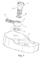
- Fig. 1 is an exploded view of two components of a banjo-type fitting.
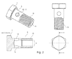
- Figures 2 , 2A and 2B illustrate, respectively, a side view, an axial section, and an external perspective view of a banjo bolt according to the known art.
- Fig. 3 illustrates an axial cross section of a banjo bolt generally according to the previous figures, installed in its final position.
- Said bolt is internally hollow, except for the head, and its internal cavity 8 opens outwardly with a hole 9 from the circular end of said body opposite said head 7; in addition, it is sized so as to perfectly fit in an airtight manner, preferably through suitable gaskets 10, 11, in said openings 3, 4.
- Said bolt is provided on its lateral cylindrical surface with one or more passages 12, 13 that put the exterior environment in communication with said internal cavity.
- said bolt Upon installation, as shown in Fig. 3 , said bolt is inserted into the corresponding eyelet so that an annular space 14 is created between the empty inside volume of the eyelet and the cylindrical external surface of the bolt.
- Said bolt is initially inserted through said openings 3, 4 of the eyebolt, and then it is screwed in with its corresponding screw thread 16 in a corresponding thread in the supporting container 17 on which it is applied.
- said annular space 14 is thus put automatically into communication with both the duct 15 inside said lateral extension 5 and, through said passages 12, 13, with said internal cavity 8, and therefore, through said hole 9, with the external environment of its intended use.
- said bolt is formed using known material deformation processes, including in particular cold forging.
- the head 20 of the bolt itself is initially formed from a first pressing or forging operation, and said head 20 is subsequently shaped as desired, usually in a square or hexagonal shape.
- the duration of the machining "step”, that is, the sum of the machining time and the time for transferring the components from one station to the next must naturally be the same.
- step of the transfer machine must be compatible with the speed or pace of the machine or of the slower machining step.
- drilling too is a rather long operation compared to the other machining processes.
- the drilling operation requires an overall average time of more than 3 seconds.
- the productivity of the whole processing line drops drastically to a value of not more than 10-20% of the rate theoretically achievable if drilling was not required.
- the main objective of the present invention is therefore to realize a method for the production of bolts to be used in said fittings for fluids known as "banjo fittings" that eliminates the drawback and the limit of productivity described above in a simple and safe manner, and preferably using widely known and tested techniques and processing methods.
- the present description refers specifically to a bolt or a part of a fitting of banjo type, but it is understood that the invention applies to all those cases in which there is a necessity to create one or more holes on the side wall of a hollow cylindrical element, and to maintain the outside diameter of the same element within defined limits.
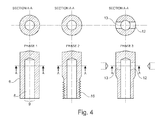
- Said machining phase is carried out, according to the teaching of the invention, preferably by means of a known through punching method, so as to eliminate in the punching area a small slug or cylinder 22, which falls spontaneously away from the bolt.
- Said punching operation can be achieved in a suitably equipped and controlled workstation, and moreover it can normally be carried out in the same transfer line that performs the other operations required to form the internal cavity 8 and the screw thread.
- portion "R" on which rolling is carried out are formed the thread grooves desired, but in the portions between one groove and the next the material, squeezed by said pressure, is shifted and concentrates in a configuration of creased type having a cross section of triangular type.
- a known method and practice is to carry out a preliminary work phase 3A in which the outside diameter of the portion of the bolt, in said portion "R" on which the threading is to be formed, is suitably reduced; obviously, such operation must take place before rolling, naturally in order not to ruin the newly rolled threads.
- the present improvement proposes to apply, during the production cycle of the bolt according to the invention, an operation to reduce the diameter 3A of the external surface of the portion "R” of the bolt concerned, and a subsequent rolling operation 4A on the same portion "R", whose outside diameter has just been reduced, in order to create the desired threading.
- said reduction operation can also be achieved on the same transfer line used for the other previously described operations, and can also be carried out through a normal well-known drawing operation.
- a further and readily appreciable improvement can also be achieved by applying the above-described operation 3A of reducing the diameter of the portion of the bolt involved "R", in a phase following the punching phase 2A explained earlier; otherwise, in fact, the newly punched out slug 22 within the cavity 8 of the bolt could be prevented from falling outside the bolt due to the hindrance caused by the reduction of the diameter of the exit hole 9 from said cavity 8.
- the present invention teaches how to manufacture a fitting of banjo type, in which:
- a further improvement of the process consists of the following: with reference to the same Fig. 5 , it may happen that the punching of the bolt could cause an undesirable permanent deformation of the bolt walls, obviously toward the inside; in addition, if the walls are not absolutely rigid, the elastic deformation of the same walls toward the inside during punching could be to an extent such as to prejudice the effectiveness and the quality of the punching process, that is, the perforation of the bolt.
- a rigid and substantially cylindrical element 25, if necessary slightly flared, of a size that allows it to be readily inserted into said opening 9 and to fill almost completely the entrance cross section is inserted into said cavity 8.
- Such operation is naturally facilitated by forming the head 26 of said rigid element 25 in a flared shape.
- said rigid element 25 serves as an anvil, on which the external annular wall of the bolt rests during the punching phase and that thus substantially prevents any temporary or permanent deformation of the external wall of the bolt.
- said slugs could remain trapped inside the fitting and, when it is installed, they could be carried directly in the flow of circulating liquid, thus creating serious risks, including the plugging of the circuit itself.
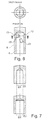
- said passages 12 and 13 are formed not by means of the above-described punching operation, but means of a shearing operation, in which two portions of the cylindrical shank 6 of the bolt are "sheared" by respective suitable tools 30, 31, so as to still form said passages 12, 13.
- Said shearing operation must however be carried out with wedge-shaped tools so as to only shear an external profile that is not closed, that is, with an open perimeter approximately in the shape of a "U”, as shown in Fig. 9B .
- the shape of said tools 30, 31 must be such as to make it possible to cut only one part of the external surface of the bolt shank 6, so as to create respective flaps 32, 33 that are bent inwardly in the internal cavity 8 of the bolt, and that still remain firmly connected to the body 6 of the bolt through the portions 34, 35 that are not affected by the shearing operation, but are only bent.
- said tools must be inserted to a sufficient depth to suitably open the two passages 12, 13 from outside to said internal cavity 8, to allow the normal outflow of the liquid.
- the size and geometry of the elements involved will be such that said bending portions 34, 35 are of suitable width, and bent sufficiently little to ensure that said flaps 32, 33 cannot absolutely become detached even in the worst conditions of use; the optimal parameters of said characteristics are however easily recognized by a person skilled in the art.
- said rigid element 25 can also be used with advantageous effects in this embodiment.
Landscapes
- Engineering & Computer Science (AREA)
- Mechanical Engineering (AREA)
- General Engineering & Computer Science (AREA)
- Self-Closing Valves And Venting Or Aerating Valves (AREA)
- Forging (AREA)
Applications Claiming Priority (1)
| Application Number | Priority Date | Filing Date | Title |
|---|---|---|---|
| IT000095A ITPN20080095A1 (it) | 2008-12-24 | 2008-12-24 | Procedimento perfezionato per la realizzazione di un raccordo per fluidi, e raccordo cosi' prodotto. |
Publications (1)
| Publication Number | Publication Date |
|---|---|
| EP2202012A1 true EP2202012A1 (de) | 2010-06-30 |
Family
ID=41075567
Family Applications (1)
| Application Number | Title | Priority Date | Filing Date |
|---|---|---|---|
| EP09178959A Withdrawn EP2202012A1 (de) | 2008-12-24 | 2009-12-11 | Verfahren zur Herstellung einer Armatur für Flüssigkeiten |
Country Status (2)
| Country | Link |
|---|---|
| EP (1) | EP2202012A1 (de) |
| IT (1) | ITPN20080095A1 (de) |
Cited By (1)
| Publication number | Priority date | Publication date | Assignee | Title |
|---|---|---|---|---|
| EP2899443A1 (de) * | 2014-01-22 | 2015-07-29 | Hung-I Hsu | Rohrleitungsbefestigungsmittel |
Citations (5)
| Publication number | Priority date | Publication date | Assignee | Title |
|---|---|---|---|---|
| US1521866A (en) * | 1923-11-30 | 1925-01-06 | Rockwood Sprinkler Co | Device for punching side holes in tubular articles |
| US3156285A (en) * | 1960-03-31 | 1964-11-10 | Layne & Bowler Inc | Apparatus for providing openings in a tubular work piece |
| DE2531711A1 (de) * | 1975-07-16 | 1977-01-20 | Berg Kg | Anschlusshohlschraube |
| DE2540096A1 (de) * | 1975-09-09 | 1977-03-17 | Selzer & Co Kg | Hohlschraube fuer den anschluss von stroemungsmittelleitungen und verfahren zu ihrer herstellung |
| GB2318313A (en) * | 1996-10-16 | 1998-04-22 | Honda Motor Co Ltd | Combined processing apparatus |
-
2008
- 2008-12-24 IT IT000095A patent/ITPN20080095A1/it unknown
-
2009
- 2009-12-11 EP EP09178959A patent/EP2202012A1/de not_active Withdrawn
Patent Citations (5)
| Publication number | Priority date | Publication date | Assignee | Title |
|---|---|---|---|---|
| US1521866A (en) * | 1923-11-30 | 1925-01-06 | Rockwood Sprinkler Co | Device for punching side holes in tubular articles |
| US3156285A (en) * | 1960-03-31 | 1964-11-10 | Layne & Bowler Inc | Apparatus for providing openings in a tubular work piece |
| DE2531711A1 (de) * | 1975-07-16 | 1977-01-20 | Berg Kg | Anschlusshohlschraube |
| DE2540096A1 (de) * | 1975-09-09 | 1977-03-17 | Selzer & Co Kg | Hohlschraube fuer den anschluss von stroemungsmittelleitungen und verfahren zu ihrer herstellung |
| GB2318313A (en) * | 1996-10-16 | 1998-04-22 | Honda Motor Co Ltd | Combined processing apparatus |
Cited By (1)
| Publication number | Priority date | Publication date | Assignee | Title |
|---|---|---|---|---|
| EP2899443A1 (de) * | 2014-01-22 | 2015-07-29 | Hung-I Hsu | Rohrleitungsbefestigungsmittel |
Also Published As
| Publication number | Publication date |
|---|---|
| ITPN20080095A1 (it) | 2010-06-25 |
Similar Documents
| Publication | Publication Date | Title |
|---|---|---|
| DE102005052360B4 (de) | Stanzniet | |
| EP2655202B1 (de) | Ausgiesser, verfahren zum herstellen eines ausgiessers und behälter umfassend einen derartigen ausgiesser | |
| EP1979108B1 (de) | Stanze und verfahren zur herstellung einander gegenüberliegender löcher in einem hohlen teil und damit hergestelltes teil | |
| JPH03242408A (ja) | 中空エンジンバルブの製造方法 | |
| DE19647962C1 (de) | Verfahren und Einrichtung zum Herstellen von Löchern am Umfang eines Hohlprofiles | |
| DE68914129T2 (de) | Matrize zum Strangpressen von Metallen. | |
| DE102015109255A1 (de) | Verfahren zum Befestigen eines Nietelements und entsprechendes Befestigungssystem | |
| KR20140061427A (ko) | 블라인드 리벳 및 공작물 배열 | |
| EP2181783A1 (de) | Stange und Verfahren zu ihrer Herstellung | |
| EP0957273A1 (de) | Befestigungselement und Verfahren zu dessen Herstellung | |
| EP2202012A1 (de) | Verfahren zur Herstellung einer Armatur für Flüssigkeiten | |
| EP3009695B1 (de) | Verformbare hülsenmutter und verfahren zur herstellung davon | |
| JPWO2006126622A1 (ja) | 孔開け加工方法及び孔開け加工装置 | |
| EP3366384A1 (de) | Verfahren zum herstellen eines blindniets, blindniet und befestigungsanordnung | |
| US8978431B1 (en) | Punch and method for piercing holes with a retention structure | |
| DE19859208A1 (de) | Metallisches Befestigungsteil und Verfahren zu seiner Herstellung | |
| EP3936730B1 (de) | Funktionselement | |
| EP3302848A1 (de) | VERFAHREN UND FÜGEELEMENT ZUM FÜGEN WENIGSTENS ZWEIER BAUTEILE MITTELS EINER FLIEßFORMNIETHÜLSE | |
| EP3875888B1 (de) | Zerlegergeschoss | |
| EP3880977B1 (de) | Vollstanzniet | |
| EP1995475B1 (de) | Unrunde Stanzmutter | |
| DE102019116338B3 (de) | Verfahren zur Herstellung eines Schraubelementrohlings sowie eines Schraubelements und Schraubelementrohling sowie Schraubelement | |
| US20250326026A1 (en) | Method of manufacturing banjo bolt | |
| DE102005035838A1 (de) | Käfig eines Rollenlagers | |
| EP2296835B1 (de) | Verfahren zur erzeugung einer öffnung in einem hohlkörperelement und vorrichtung zur durchfürung des verfahrens |
Legal Events
| Date | Code | Title | Description |
|---|---|---|---|
| PUAI | Public reference made under article 153(3) epc to a published international application that has entered the european phase |
Free format text: ORIGINAL CODE: 0009012 |
|
| AK | Designated contracting states |
Kind code of ref document: A1 Designated state(s): AT BE BG CH CY CZ DE DK EE ES FI FR GB GR HR HU IE IS IT LI LT LU LV MC MK MT NL NO PL PT RO SE SI SK SM TR |
|
| AX | Request for extension of the european patent |
Extension state: AL BA RS |
|
| STAA | Information on the status of an ep patent application or granted ep patent |
Free format text: STATUS: THE APPLICATION IS DEEMED TO BE WITHDRAWN |
|
| 18D | Application deemed to be withdrawn |
Effective date: 20101231 |