EP2201854B1 - Sole - Google Patents
Sole Download PDFInfo
- Publication number
- EP2201854B1 EP2201854B1 EP09179920.5A EP09179920A EP2201854B1 EP 2201854 B1 EP2201854 B1 EP 2201854B1 EP 09179920 A EP09179920 A EP 09179920A EP 2201854 B1 EP2201854 B1 EP 2201854B1
- Authority
- EP
- European Patent Office
- Prior art keywords
- sole
- bending element
- bending
- shoe
- blocks
- Prior art date
- Legal status (The legal status is an assumption and is not a legal conclusion. Google has not performed a legal analysis and makes no representation as to the accuracy of the status listed.)
- Active
Links
- 238000005452 bending Methods 0.000 claims description 220
- 238000007373 indentation Methods 0.000 claims description 37
- 210000002683 foot Anatomy 0.000 claims description 29
- 239000000463 material Substances 0.000 claims description 19
- 210000004744 fore-foot Anatomy 0.000 claims description 16
- 210000001872 metatarsal bone Anatomy 0.000 description 10
- 238000001746 injection moulding Methods 0.000 description 8
- 230000000903 blocking effect Effects 0.000 description 6
- 210000003371 toe Anatomy 0.000 description 6
- 238000013016 damping Methods 0.000 description 4
- 238000004519 manufacturing process Methods 0.000 description 4
- 238000000034 method Methods 0.000 description 4
- 239000000243 solution Substances 0.000 description 4
- 230000007704 transition Effects 0.000 description 4
- 210000000452 mid-foot Anatomy 0.000 description 3
- 230000003014 reinforcing effect Effects 0.000 description 3
- 208000027418 Wounds and injury Diseases 0.000 description 2
- 230000006378 damage Effects 0.000 description 2
- 230000002950 deficient Effects 0.000 description 2
- 208000014674 injury Diseases 0.000 description 2
- 230000001105 regulatory effect Effects 0.000 description 2
- 206010024453 Ligament sprain Diseases 0.000 description 1
- 208000010040 Sprains and Strains Diseases 0.000 description 1
- 239000003086 colorant Substances 0.000 description 1
- 239000002131 composite material Substances 0.000 description 1
- 230000007423 decrease Effects 0.000 description 1
- 230000001419 dependent effect Effects 0.000 description 1
- 230000010354 integration Effects 0.000 description 1
- 230000003287 optical effect Effects 0.000 description 1
- 229920002647 polyamide Polymers 0.000 description 1
- 230000002787 reinforcement Effects 0.000 description 1
- 238000010008 shearing Methods 0.000 description 1
- 238000005728 strengthening Methods 0.000 description 1
- 239000012780 transparent material Substances 0.000 description 1
Images


Classifications
-
- A—HUMAN NECESSITIES
- A43—FOOTWEAR
- A43B—CHARACTERISTIC FEATURES OF FOOTWEAR; PARTS OF FOOTWEAR
- A43B13/00—Soles; Sole-and-heel integral units
- A43B13/14—Soles; Sole-and-heel integral units characterised by the constructive form
- A43B13/141—Soles; Sole-and-heel integral units characterised by the constructive form with a part of the sole being flexible, e.g. permitting articulation or torsion
Definitions
- the present invention relates to a sole for a shoe, in particular for football shoes.
- Sports shoes not only fulfil a particular function in a respective discipline by supporting a particular movement or by providing a good ground contact. They also have to protect the foot from exterior impact or prevent wrong movements, in order to avoid injuries.
- German utility model DE 19 73 891 describes a football shoe which provides grooves in the metatarsal area whose side walls are provided with a layer which is harder than the material of the sole (cf. Fig. 1 to 4 ). It is further suggested to also improve rigidity in the forefoot area by providing an extension away from the sole transversal to the longitudinal direction of the sole. Another sole with grooves in the metatarsal area is described in the German patent application DE 2 022 974 .
- German patent D 32 19 652 describes a football shoe whose sole has areas with different degrees of hardness and which are arranged in the forefoot area. Recesses or grooves transversal to the sole are provided in order to save weight.
- EP 1 074 194 discloses a structure for a sole in which alternating soft and hard elements are arranged as transversal grooves in a layer of a sole.
- German patent application DE 10 2008 020 890 A1 describes a sole with a strengthening element comprising several plates which are connected by hinges.
- US patent US 6,715,218 describes a support device which is flexible in one direction and which is rigid in a different direction. This device can be incorporated into a variety of articles of sports equipment, such as sports shoes.
- German patent application DE 35 16 545 describes a goal keeper glove with elements on the backside of the hand, in order to avoid a hyperextension of the fingers to the back side.
- the present invention solves this problem in a first embodiment with a sole for a shoe, according to claim 1.
- the definitions of plantar bending of the sole and dorsal bending of the sole given above apply throughout the specification and are hereafter designated simply as plantar bending and dorsal bending.
- the present invention not only provides protection against a hyperextension of the foot but also high movability for a user of the shoe.
- Applicant of the present invention has recognized the problem that the known solutions impede the movability of the user of the shoe since the known elements for enforcing a sole comprise a significant part of the width of the sole and thereby hamper a lateral rolling-up of the foot.
- Such lateral movements occur in particular during lateral sports such as football, for example when the player performs many directional changes of his movement during dribbling.
- the directional changes require lateral rolling-up of the foot from a medial edge to a lateral edge of the foot and vice versa.
- a "slim" bending element which extends across less than half of the width of the sole enables also a lateral rolling-up of the foot since the sole is less rigid than the bending element.
- the arrangement of the bending element in the forefoot area protects this particularly sensitive area of the foot against hyperextension.
- the bending element is located along a centreline of the sole.
- a central arrangement enables a uniform lateral rolling-up on both sides of the centreline.
- a sole fulfils the requirements of avoiding a hyperextension of the foot and rolling-up in along a longitudinal axis of the sole.
- the width of the bending element comprises less than a third of the width of the sole.
- lateral rolling-up is in addition improved by further reducing the width of the bending element.
- the reduced elasticity of the sole in the area where the bending element is arranged is limited correspondingly.
- the width of the bending element varies along a longitudinal axis of the sole.
- the bending element extends to an area of the toes of the sole.
- the flexibility leads to the particular risk of plantar hyperextension of the sensitive toes. Extending the bending element to the area of the toes therefore improves the protection of the toes and simultaneously enables lateral rolling-up of the sole also in this area.
- the unidirectional bending element is arranged at a first layer of the sole and vertically projects from the first layer.
- the bending element is arranged on a side of the first layer away from the foot.
- the width of the bending element comprises less than half of the width of the sole. This leads to the same advantages described above in connection with the first embodiment.
- the bending element is arranged in a recess or opening of the first layer.
- the bending element can be separately manufactured and subsequently arranged in a mould for injection moulding.
- the first layer of the sole is then manufactured by injection moulding around the bending element. In this way, the bending element itself serves as a mould for the recess or opening in the first layer of the sole.
- the sole may be an inlay sole, an insole or an intermediate sole.
- the sole is an outsole, wherein the bending element is preferably covered by a transparent material, in order to protect the bending element.
- the sole comprises a second layer, wherein the second layer comprises an indentation for the bending element.
- the bending element can be integrated into the sole.
- this only requires an indentation in a second layer of the sole. This is significantly simpler than a design in which a whole layer of a sole is designed as a reinforcing element.
- the indentation has a shape corresponding to the bending element. This facilitates fixing the first layer with the bending element connected thereto to the second layer and avoids slipping.
- the first layer is an inlay sole or an insole and the second layer is an insole or an intermediate sole.
- the first layer is an insole or an intermediate sole and the second layer is an outsole.
- the outsole comprises a transparent area through which the bending element is visible. This allows an optical control of the function of the bending element and to check the selection of the bending element in case the bending element is exchangeable. For example, different colours may index different properties of the exchangeable bending elements and enable identification.
- the transparent area enables recognition of the specific bending element in use.
- the bending element is releasably attached (for example using a clip system) to the outside of the outsole. In this embodiment it is particularly simple to exchange the bending element from the outside without having to take off the shoe.
- the bending element comprises blocks which are separated by indentations.
- the indentations preferably run orthogonal to a longitudinal axis of the bending element.
- the bending element further comprises a plastic plate to which the blocks are attached. The indentations therefore act as hinges between the blocks and enable bending of the bending element.
- the distances between the indentations in the direction of the longitudinal axis of the bending element are smaller than the widths of the blocks in the direction orthogonal to the longitudinal axis of the bending element. This causes stability in the direction orthogonal to the longitudinal axis of the bending element and further ensures that the bending of the bending element is essentially limited to a bending plane which runs orthogonal to the plane of the bending element along the longitudinal axis of the bending element.
- angles between the indentations and the longitudinal axis are not equal to 90° and / or are different from each other.
- the bending of the bending element deviates from the previously described bending plane and leads to a torsion away from the bending plane. This can be advantageous to support but also to limit particular movements. For example, a natural rolling-up of the foot in one direction can be supported, and an undesired contortion of the foot (sprain) in a different direction can be avoided.
- the blocks of the bending element comprise materials with different properties, in particular elasticity. This avoids a sudden blocking of the plantar bending of bending element but rather leads to first moderating the plantar bending before blocking it. This bending process can be regulated by properties of the material.
- the distances between the indentations between the blocks are different.
- single blocks of the bending element may comprise a higher elasticity than others which results in a soft transition between the movement range in which the bending element is bendable and the movement range in which it blocks.
- a further embodiment relates to a corresponding shoe which comprises an indentation for a bending element of an inlay sole. In this way, a shoe can be equipped in a particularly simple way with a bending element. Since it is an inlay sole, the bending element can be easily exchanged together with the inlay sole. This allows the selection of a bending element from bending elements having different bending properties.
- a sole for a shoe in particular for a football shoe.
- the present invention is not limited to a sole for a football shoe but can be applied to other sports shoes and non-sporting shoes, in order to avoid a plantar hyperextension of the foot (bending of the foot in the direction downward and towards the ground) without limiting the movability during use of the shoe.
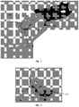
- Fig. 1 shows a perspective bottom view of an embodiment of sole 100 for a shoe having a bending element.
- an insole for a football shoe with a forefoot area 110, a metatarsal area 120 and a heel area 130 can be recognized.
- the insole is designated as sole 100 in the following.
- a bending element 150 is arranged which essentially extends along a centre line of sole 100. The centre line runs in a longitudinal direction of sole 100 and has an essentially equal distance to both edges of sole 100.
- the bending element is arranged in other areas of the sole, for example in metatarsal area 120, or extends across several areas, for example across metatarsal area 120 and forefoot area 110. Further, bending element 150 can be shifted and/or skewed with respect to the centre line of the sole.
- the width of the bending 150 is substantially smaller than the width of sole 100 at the same point.
- the width of bending element 150 is less than half of the width of sole 100.
- the width of bending element 150 is less than a third of the width of sole 100. Since sole 100 is less rigid than bending element 150, this facilitates bending in a transversal direction of the sole. This enables a lateral rolling-up of the foot when a shoe having this sole (which significantly improves the movability of the foot) is used.
- bending element 150 comprises a plurality of blocks 151 separated by indentations 152.
- Indentations 152 are essentially straight and run orthogonal to a longitudinal axis of bending element 150. Indentations 152 ensure that bending element 150 and sole 100 attached thereto can be bent in the dorsal direction, i.e. in the direction upward and towards the foot (in fig. 1 downwards). Bending in the opposite, i.e. plantar direction (in fig. 1 upwards) is, however, not possible since the side walls of blocks 151 contact each other during bending in the plantar direction and therefore block further bending.
- the distances of the indentations 152 between the blocks 151 in the direction of the longitudinal axis of bending element 150 are smaller, preferably multiple times smaller than the widths of blocks 151 in the direction orthogonal to the longitudinal axis of bending element 150, as can also be recognized in Fig. 1 .
- This causes stability of bending element 150 orthogonal to its longitudinal axis and further ensures that bending of bending element 150 is essentially limited to a bending plane which runs orthogonal to the plane of bending element 150 along the longitudinal axis of bending element 150.
- indentations 152 are essentially not orthogonal to the longitudinal axis of bending element 150. Further, the angle between indentations 152 and the longitudinal axis of bending element 150 can be different from each other. In these embodiments the bending of bending element 150 deviates from the previously described bending plane and leads in particular to a torsion beyond the bending plane. This can be advantageous for a support but also a limitation of particular movements. In further embodiments (see below in fig. 8 ) the indentations of the bending element are curved in a bottom view or a top view. The curved indentations reduce the risk of shearing during torsion.
- blocks 151 of bending element 150 comprise materials of different properties, in particular of different elasticity. Elasticity and weight of the bending element may influence, for example, the power of shot.
- An example for a particularly well suited material is Polyamid PA 6. This allows controlled deceleration and blocking of bending element 150 during plantar bending of sole 100.
- single blocks 151 of bending element 150 may be more elastic than other blocks so that there is a soft transition between the movement range in which bending element 150 is bendable and the movement range in which it blocks.
- Fig. 1 further shows that the width of bending element 150 varies along the longitudinal axis of sole 100.
- bending element 150 has a larger width in areas of a larger sole width, and bending element 150 has a smaller width in areas of a smaller sole width.
- Fig. 1 further shows that bending element 150 vertically projects from the first layer of sole 100.
- the second layer has to comprise an indentation which preferably corresponds to the shape of bending element 150.
- sole 100 illustrated in Fig. 1 may be an insole, an intermediate sole or an outsole. If it is an outsole, the bending element can be arranged in one embodiment on the side of the outsole away from the foot. In this case, the bending element is protected by a preferably transparent cover. In a further embodiment, the bending element is arranged on the side of the outsole directed towards the foot. In this case, the sole layer arranged on the side of the bending element comprises an indentation for receiving the bending element.
- Fig. 2 is a perspective view of the bending element of fig. 1 .
- the bending element 150 with blocks 151 and indentations 152 between blocks 151 can be recognized.
- a plastic plate 155 can be recognized to which blocks 151 are attached.
- Plastic plate 155 extends beyond the area of blocks 151 and can be used for connection with a sole, as explained in more detail in the following in connection with fig. 3 .
- Fig. 2 also shows that bending element 150 is curved in the initial state shown in this figure.
- the blocks are connected to each other by a circumferential plastic strap.
- Bending element 150 is injection-moulded in one piece. This may comprise one-component injection moulding or multi-component (different materials) injection moulding.
- the pre-curvature of the bending element is possible due to the method of manufacture in which the indentations can be generated by mould slides (in the curved state the indentations are "open").
- the mould slides can be arranged in parallel and may therefore be taken out in a single direction.
- the dorsal pre-tension further supports the rolling-up properties of the sole and minimizes a blocking tolerance. This will be explained in more detail in connection with fig. 3 .
- Fig. 3 is a further side view of the bending element from Fig. 1 and Fig. 2 .
- Bending element 150 with blocks 151 and indentations 152 as well as plastic plate 155 can be recognized in fig. 3 . In this view it is clearly visible that bending element 150 is curved in its initial state.
- indentations 152 are essentially parallel in their initial state in the side view of fig. 3 .
- Bending element 150 may therefore be manufactured in a simple way by an appropriate method using a mould. Indentations 152 are formed by placing mould slides inside the mould. The result is a bending element 150 which is curved in its initial state.
- Fig. 3 further shows that plastic plate 155 is graded and comprises an area 156 with a larger thickness.
- the thickness of graded area 156 varies along bending element 150 and increases in particular from the forefoot area to the midfoot area (i.e., from left to right in fig. 3 ). This property is relevant when connecting the bending element to a sole, for example an insole, as explained in the following.
- Bending element 150 can be arranged in an indentation of a sole, for example an inlay sole, an insole, an intermediate sole or an outsole, and attached to the sole.
- the sole is manufactured around bending element 150, using an appropriate method, for example injection moulding, so that bending element 150 itself forms a mould for the indentation.
- plastic plate 155 forms part of the surface of sole 100, and the thickness of sole 100 corresponds to the thickness of the graded area 156. Therefore, the area of plastic plate 155 up to graded area 156 is available as a surface for connection to the sole 100 and therefore provides a good bonding. A variable thickness of graded area 156 therefore leads to a correspondingly varying thickness of sole 100. Bending element 150 shown in Fig. 3 would lead to a thickness of a sole (attached thereto) which increases from forefoot area to the midfoot area, corresponding to the thickness of graded area 156.
- Fig. 4 is a perspective bottom view of a further embodiment of a sole 400 for a shoe with a bending element.
- the figure shows an inlay sole, in particular for a football shoe, having a forefoot area 410, a metatarsal area 420 and a heel area 430.
- a bending element 450 is arranged in forefoot area 410 of the inlay sole. Bending element 450 extends on the one side to the area of the toes and on the other side to metatarsal area 420. Bending element 450 is curved towards the lateral side of inlay sole 400.
- bending element 450 is arranged in other areas of sole 400, for example in metatarsal area 420, or it extends across several areas, for example across metatarsal area 420 and forefoot area 410. Further, the bending element can be curved differently and can be arranged, for example, along a centreline of the inlay sole.
- the width of bending element 450 is substantially smaller than the width of inlay sole at the same point.
- the statements on the widths of bending element 150 with respect to fig. 1 to 3 also apply to the embodiment of fig. 4 .
- Fig. 4 also shows that bending element 450 comprises a plurality of blocks 451, 461 which are separated by indentations 452. Also here the statements on blocks 151 and indentations 152 made with respect to fig. 1 to 3 apply. However, in contrast to fig. 1 , the distances between indentations 452 in the direction along the longitudinal axis of the bending element 450 are different. In other words, there are shorter blocks 461 and longer blocks 451. Further, a plastic plate 455 can be seen to which blocks 451, 461 are attached.
- Bending element 450 can be manufactured by multi-component injection moulding so that bending element is made from one piece. Alternatively, the bending element could be made from two pieces moulded separately which are attached to each other after injection moulding. This is described, for example, in US patent 6,725, 218 of applicant mentioned in the introduction.
- the different sizes of the blocks 451, 461 play a role when using materials with different properties for the blocks for regulating the damping of bending element 450.
- shorter blocks 461 may comprise a material having a larger elasticity than the material of the longer blocks 451. In this way, the transition between the movement range in which bending element 450 is bendable and the movement range in which it blocks is dampened. If longer blocks 451 are made from a material having a larger elasticity than the material of shorter blocks 461, then the damping is even increased.
- a bending element 450 with blocks made from different materials can be manufactured in a simple way by multi-component injection moulding.
- plastic plate 455 and blocks 461 may comprise a first material
- blocks 451 may comprise a second material.
- a damping element 490 is arranged in heel area 430.
- a further embodiment of the invention (not illustrated) relates to a corresponding shoe which comprises an insole with an indentation for a bending element of an inlay sole.
- a shoe can be equipped in a particularly simple way with a bending element. Since it is an inlay sole, the inlay sole together with the bending element can be easily exchanged. Depending on needs and personal preferences, bending elements having different properties with respect to weight, stiffness, size etc. can be used. Similarly, defective bending elements can be exchanged at low cost. It is also conceivable that the bending element is releasably attached to the inlay sole so that, depending on the needs, the bending element or the inlay sole can be exchanged.
- Fig. 5 shows a bottom view of a football shoe with a sole 500 and a bending element 550.
- a transparent area 540 can be recognized which is arranged in forefoot area 510 of the second layer of sole 500 and which provides a view on bending element 550 arranged under transparent area 540.
- Fig. 6 shows schematic representations of an embodiment of a shoe with a sole and a bending element. Specifically, a bottom view of a football shoe having a sole 600 and a bending element 650 are shown. Fig. 6 further shows a cross section of the football shoe and of bending element 650.
- Fig. 7 illustrates a further schematic representation of a football shoe.
- fig. 7 shows a schematic longitudinal section of a sole 700 having a bending element 750.
- the thickness of bending element 750 varies along the longitudinal axis of the shoe. Specifically, the thickness initially increases from the midfoot area to the forefoot area and then decreases again.
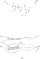
- Fig. 8 shows schematic representations of a further embodiment of a sole 800 having a bending element 850, in particular a cross section 801 along line B-B, a side view 802, and a bottom view 803.
- Bending element 850 which is shown in all views is arranged in the forefoot area and extends to the toe area.
- Sole 850 can be made of two materials which are shown in cross section 801 to be connected along a transition /overlap zone. The overlap of the two materials is dimensioned with 0,6 mm and 0,5 mm.
- the bending element 850 is dimensioned with 1,80 mm and 3,92 mm.
- the bending element is arranged in a recess of the sole with a depth of 0,41 mm.
- the side view 802 shows that bending element 850 projects from sole 800, wherein the thickness of bending element 850 essentially remains constant.
- the bottom view 803 of sole 800 shows that indentations 852 of bending element 850 are curved.
- the dimensions depicted in Fig. 8 are only examples and may vary in other embodiments.
- the bending elements in a sole can be exchanged, in order to facilitate customising the shoe to particular requirements of movements or in order to exchange defective elements.
- a selection between bending elements with different bending properties is possible, as for example explained above in connection with the use of different materials of a bending element.
- bending properties can also be influenced by various mechanical properties, for example different sizes of the blocks of a bending element, different distances between the indentations between the blocks, or a varying thickness of the bending element.
- the bending elements may be designed so that they facilitate customising the elasticity of the bending element, for example by a screw which adapts an elasticity area of an elastic element of the bending element.
- the movement of a user of a shoe is detected by a control system using sensors, which in response correspondingly adapts the elasticity of the bending element.
- the control system could detect the difference between a running movement and a movement for shooting a ball and correspondingly increase the elasticity during running and reduce the elasticity during a shot.
Description
- The present invention relates to a sole for a shoe, in particular for football shoes.
- Sports shoes not only fulfil a particular function in a respective discipline by supporting a particular movement or by providing a good ground contact. They also have to protect the foot from exterior impact or prevent wrong movements, in order to avoid injuries.
- Risks of this kind arise in football when the player comes into contact with a ball. During this contact, enormous forces may act on the instep of the foot which hyperextend the foot in the direction of the sole (plantar), for example during a shot or when the opponent blocks the ball. In an extreme case a player with a high running speed may get his foot stuck in the ground. This leads to a sudden blocking of this high speed movement. The blocking may cause a plantar hyperextension of the foot and may lead to a painful injury.
- The risk of such a plantar hyperextension could be effectively avoided with a rigid sole; on the other hand, this would disable the football shoe for fast movements since a rigid sole impedes an elastic rolling-up of the foot.
- Several attempts have been have in the prior art to provide a sole which is rigid against plantar hyperextension while simultaneously enabling rolling-up of the foot. Such attempts are also known for other areas of the shoe or for gloves.
- The German utility model
DE 19 73 891 describes a football shoe which provides grooves in the metatarsal area whose side walls are provided with a layer which is harder than the material of the sole (cf.Fig. 1 to 4 ). It is further suggested to also improve rigidity in the forefoot area by providing an extension away from the sole transversal to the longitudinal direction of the sole. Another sole with grooves in the metatarsal area is described in the German patent applicationDE 2 022 974 . - Similarly, the German patent D
32 19 652 describes a football shoe whose sole has areas with different degrees of hardness and which are arranged in the forefoot area. Recesses or grooves transversal to the sole are provided in order to save weight. - The European patent application
EP 1 074 194 discloses a structure for a sole in which alternating soft and hard elements are arranged as transversal grooves in a layer of a sole. - The German patent application
DE 10 2008 020 890 A1 describes a sole with a strengthening element comprising several plates which are connected by hinges. - The patent application
US 2007/0107265 discloses a flexible sole with segments in the metatarsal area which can be articulated. However, this application is based on a problem opposite to that of the present application, namely to support a strong bending of the arch of the foot, for example during dancing. - Further, US patent
US 6,715,218 describes a support device which is flexible in one direction and which is rigid in a different direction. This device can be incorporated into a variety of articles of sports equipment, such as sports shoes. - The German patent application
DE 35 16 545 describes a goal keeper glove with elements on the backside of the hand, in order to avoid a hyperextension of the fingers to the back side. - A further sole with tension elements which protect against hyperextension is described in the German utility model
DE 201 10 084 U1 . European patent applicationEP1074194 describes a sole with a composite structure situated in the forefoot region, which protects against counter-bending of the sole. The previous solutions which are aimed at preventing plantar hyperextension of the foot are not satisfactory since they impede the movability of the wearer of the shoe and do not fulfil general biomechanical requirements to smooth movements. Further, the manufacture of the described devices is complex. It is therefore the problem of the present invention to overcome the disadvantages of the prior art and to provide in particular a sole which avoids plantar hyperextension of the foot without limiting the movability of the shoe during use. Further, the sole should be manufactured easily. - The present invention solves this problem in a first embodiment with a sole for a shoe, according to claim 1. Similarly, the definitions of plantar bending of the sole and dorsal bending of the sole given above apply throughout the specification and are hereafter designated simply as plantar bending and dorsal bending.
- In contrast to the solutions in the prior art, the present invention not only provides protection against a hyperextension of the foot but also high movability for a user of the shoe. Applicant of the present invention has recognized the problem that the known solutions impede the movability of the user of the shoe since the known elements for enforcing a sole comprise a significant part of the width of the sole and thereby hamper a lateral rolling-up of the foot. Such lateral movements occur in particular during lateral sports such as football, for example when the player performs many directional changes of his movement during dribbling. The directional changes require lateral rolling-up of the foot from a medial edge to a lateral edge of the foot and vice versa.
- In contrast to the prior art, a "slim" bending element which extends across less than half of the width of the sole enables also a lateral rolling-up of the foot since the sole is less rigid than the bending element. The arrangement of the bending element in the forefoot area protects this particularly sensitive area of the foot against hyperextension.
- Preferably, the bending element is located along a centreline of the sole. Such a central arrangement enables a uniform lateral rolling-up on both sides of the centreline. Further, such a sole fulfils the requirements of avoiding a hyperextension of the foot and rolling-up in along a longitudinal axis of the sole.
- In a preferred embodiment, the width of the bending element comprises less than a third of the width of the sole. In this narrow embodiment lateral rolling-up is in addition improved by further reducing the width of the bending element. Thereby the reduced elasticity of the sole in the area where the bending element is arranged is limited correspondingly.
- Preferably, the width of the bending element varies along a longitudinal axis of the sole. By adjusting the width of the bending element to the width of the sole in this way, a uniform lateral rolling-up is enabled.
- It is further preferred that the bending element extends to an area of the toes of the sole. In order to provide high movability during sports, it is on the one hand desirable to have a high elasticity of a shoe. On the other hand, the flexibility leads to the particular risk of plantar hyperextension of the sensitive toes. Extending the bending element to the area of the toes therefore improves the protection of the toes and simultaneously enables lateral rolling-up of the sole also in this area.
- In a preferred embodiment the unidirectional bending element is arranged at a first layer of the sole and vertically projects from the first layer. Preferably, the bending element is arranged on a side of the first layer away from the foot.
- The particular advantage of this preferred embodiment results from a unidirectional bending element enabling a modular assembly of a sole. In the prior art it is only known to modify a whole layer of a sole to act as a reinforcing element which in turn requires a complex manufacture. In contrast to this, applicant has searched for a solution enabling a modular manufacture. This is made possible by arranging the bending element on a first layer of the sole, wherein the bending element vertically projects from the first layer. In this way, the bending element can be separately manufactured and subsequently attached to a layer of a sole. Since the bending element vertically projects from the first layer, the layer itself can be significantly thinner than the bending element. Therefore, neither a particular reinforcement of the sole is required in order to make it a reinforcing element, nor does the sole have to have a minimum thickness. This is particularly advantageous if the layer of the sole is an insole which therefore can be significantly thinner than the bending element.
- In this embodiment it is also preferred that the width of the bending element comprises less than half of the width of the sole. This leads to the same advantages described above in connection with the first embodiment.
- Preferably, the bending element is arranged in a recess or opening of the first layer. This enables a proper integration of the bending element with the first layer. For example, the bending element can be separately manufactured and subsequently arranged in a mould for injection moulding. The first layer of the sole is then manufactured by injection moulding around the bending element. In this way, the bending element itself serves as a mould for the recess or opening in the first layer of the sole.
- In various embodiments, the sole may be an inlay sole, an insole or an intermediate sole. In a further embodiment, the sole is an outsole, wherein the bending element is preferably covered by a transparent material, in order to protect the bending element.
- It is further preferred that the sole comprises a second layer, wherein the second layer comprises an indentation for the bending element. In this way, the bending element can be integrated into the sole. In contrast to the prior art, this only requires an indentation in a second layer of the sole. This is significantly simpler than a design in which a whole layer of a sole is designed as a reinforcing element.
- Preferably, the indentation has a shape corresponding to the bending element. This facilitates fixing the first layer with the bending element connected thereto to the second layer and avoids slipping.
- In a preferred embodiment, the first layer is an inlay sole or an insole and the second layer is an insole or an intermediate sole. In an alternative embodiment, the first layer is an insole or an intermediate sole and the second layer is an outsole. These examples show that the claimed sole can be realized in many different ways.
- If the second layer is an outsole, it is further preferred that the outsole comprises a transparent area through which the bending element is visible. This allows an optical control of the function of the bending element and to check the selection of the bending element in case the bending element is exchangeable. For example, different colours may index different properties of the exchangeable bending elements and enable identification. The transparent area enables recognition of the specific bending element in use. Further, it is conceivable that the bending element is releasably attached (for example using a clip system) to the outside of the outsole. In this embodiment it is particularly simple to exchange the bending element from the outside without having to take off the shoe.
- In a further embodiment, the bending element comprises blocks which are separated by indentations. The indentations preferably run orthogonal to a longitudinal axis of the bending element. Preferably, the bending element further comprises a plastic plate to which the blocks are attached. The indentations therefore act as hinges between the blocks and enable bending of the bending element.
- It is preferred that the distances between the indentations in the direction of the longitudinal axis of the bending element are smaller than the widths of the blocks in the direction orthogonal to the longitudinal axis of the bending element. This causes stability in the direction orthogonal to the longitudinal axis of the bending element and further ensures that the bending of the bending element is essentially limited to a bending plane which runs orthogonal to the plane of the bending element along the longitudinal axis of the bending element.
- In further embodiments the angles between the indentations and the longitudinal axis are not equal to 90° and / or are different from each other. In these embodiments, the bending of the bending element deviates from the previously described bending plane and leads to a torsion away from the bending plane. This can be advantageous to support but also to limit particular movements. For example, a natural rolling-up of the foot in one direction can be supported, and an undesired contortion of the foot (sprain) in a different direction can be avoided.
- In a further embodiment the blocks of the bending element comprise materials with different properties, in particular elasticity. This avoids a sudden blocking of the plantar bending of bending element but rather leads to first moderating the plantar bending before blocking it. This bending process can be regulated by properties of the material.
- It is further preferred that the distances between the indentations between the blocks are different. In particular, in combination with the use of materials having different properties, this results in further possibilities to regulate the damping of the bending element during a plantar movement. For example, single blocks of the bending element may comprise a higher elasticity than others which results in a soft transition between the movement range in which the bending element is bendable and the movement range in which it blocks. A further embodiment relates to a corresponding shoe which comprises an indentation for a bending element of an inlay sole. In this way, a shoe can be equipped in a particularly simple way with a bending element. Since it is an inlay sole, the bending element can be easily exchanged together with the inlay sole. This allows the selection of a bending element from bending elements having different bending properties.
- Further preferred embodiments are described in further dependent patent claims.
- In the following aspects of embodiments of the present invention are described in more detail with respect to the accompanying figures. These figures show:
- Fig. 1:
- A perspective bottom view of an embodiment of a sole for a shoe with a bending element;
- Fig. 2:
- a perspective view of the bending element from
fig. 1 ; - Fig. 3:
- a further perspective view of the bending element from
fig. 1 ; - Fig. 4:
- a perspective bottom view of a further embodiment of a sole for a shoe with a bending element;
- Fig. 5:
- a bottom view of a football shoe with a sole having a bending element;
- Fig. 6:
- schematic section and representation of an embodiment of a shoe with a sole having a bending element;
- Fig. 7:
- schematic representation of an embodiment of a shoe with a sole having a bending element; and
- Fig. 8:
- schematic representations of an embodiment of a sole with a bending element.
- In the following embodiments of the present invention are described in more detail with respect to an example of a sole for a shoe, in particular for a football shoe. However, it is to be understood that the present invention is not limited to a sole for a football shoe but can be applied to other sports shoes and non-sporting shoes, in order to avoid a plantar hyperextension of the foot (bending of the foot in the direction downward and towards the ground) without limiting the movability during use of the shoe.
-
Fig. 1 shows a perspective bottom view of an embodiment of sole 100 for a shoe having a bending element. In the figure, an insole for a football shoe with aforefoot area 110, ametatarsal area 120 and aheel area 130 can be recognized. For simplicity, the insole is designated as sole 100 in the following. In theforefoot area 110 of sole 100 abending element 150 is arranged which essentially extends along a centre line of sole 100. The centre line runs in a longitudinal direction of sole 100 and has an essentially equal distance to both edges of sole 100. In alternative embodiments (not illustrated) the bending element is arranged in other areas of the sole, for example inmetatarsal area 120, or extends across several areas, for example acrossmetatarsal area 120 andforefoot area 110. Further, bendingelement 150 can be shifted and/or skewed with respect to the centre line of the sole. - At every point of the
bending element 150, the width of the bending 150 is substantially smaller than the width of sole 100 at the same point. In the view offig. 1 it can be recognized that the width of bendingelement 150 is less than half of the width of sole 100. In a further embodiment (not illustrated), the width of bendingelement 150 is less than a third of the width of sole 100. Since sole 100 is less rigid than bendingelement 150, this facilitates bending in a transversal direction of the sole. This enables a lateral rolling-up of the foot when a shoe having this sole (which significantly improves the movability of the foot) is used. -
Fig. 1 further shows that bendingelement 150 comprises a plurality of blocks 151 separated byindentations 152.Indentations 152 are essentially straight and run orthogonal to a longitudinal axis of bendingelement 150.Indentations 152 ensure that bendingelement 150 and sole 100 attached thereto can be bent in the dorsal direction, i.e. in the direction upward and towards the foot (infig. 1 downwards). Bending in the opposite, i.e. plantar direction (infig. 1 upwards) is, however, not possible since the side walls of blocks 151 contact each other during bending in the plantar direction and therefore block further bending. - The distances of the
indentations 152 between the blocks 151 in the direction of the longitudinal axis of bendingelement 150 are smaller, preferably multiple times smaller than the widths of blocks 151 in the direction orthogonal to the longitudinal axis of bendingelement 150, as can also be recognized inFig. 1 . This causes stability of bendingelement 150 orthogonal to its longitudinal axis and further ensures that bending of bendingelement 150 is essentially limited to a bending plane which runs orthogonal to the plane of bendingelement 150 along the longitudinal axis of bendingelement 150. - In alternative embodiments (not illustrated)
indentations 152 are essentially not orthogonal to the longitudinal axis of bendingelement 150. Further, the angle betweenindentations 152 and the longitudinal axis of bendingelement 150 can be different from each other. In these embodiments the bending of bendingelement 150 deviates from the previously described bending plane and leads in particular to a torsion beyond the bending plane. This can be advantageous for a support but also a limitation of particular movements. In further embodiments (see below infig. 8 ) the indentations of the bending element are curved in a bottom view or a top view. The curved indentations reduce the risk of shearing during torsion. - In further embodiments blocks 151 of bending
element 150 comprise materials of different properties, in particular of different elasticity. Elasticity and weight of the bending element may influence, for example, the power of shot. An example for a particularly well suited material is Polyamid PA 6. This allows controlled deceleration and blocking of bendingelement 150 during plantar bending of sole 100. For example, single blocks 151 of bendingelement 150 may be more elastic than other blocks so that there is a soft transition between the movement range in whichbending element 150 is bendable and the movement range in which it blocks. -
Fig. 1 further shows that the width of bendingelement 150 varies along the longitudinal axis of sole 100. In particular, bendingelement 150 has a larger width in areas of a larger sole width, and bendingelement 150 has a smaller width in areas of a smaller sole width. By adjusting the width of bendingelement 150 in this way to the width of sole 100, a uniform lateral rolling-up is enabled since the portion of the sole width free from the bendingelement 150 and which is more elastic than the area of bendingelement 150, remains approximately constant. -
Fig. 1 further shows that bendingelement 150 vertically projects from the first layer of sole 100. When connecting sole 100 to a second layer of the sole, i.e. an intermediate sole or an outsole, the second layer has to comprise an indentation which preferably corresponds to the shape of bendingelement 150. - In various embodiments (not shown), sole 100 illustrated in
Fig. 1 may be an insole, an intermediate sole or an outsole. If it is an outsole, the bending element can be arranged in one embodiment on the side of the outsole away from the foot. In this case, the bending element is protected by a preferably transparent cover. In a further embodiment, the bending element is arranged on the side of the outsole directed towards the foot. In this case, the sole layer arranged on the side of the bending element comprises an indentation for receiving the bending element. -
Fig. 2 is a perspective view of the bending element offig. 1 . The bendingelement 150 with blocks 151 andindentations 152 between blocks 151 can be recognized. Further, aplastic plate 155 can be recognized to which blocks 151 are attached.Plastic plate 155 extends beyond the area of blocks 151 and can be used for connection with a sole, as explained in more detail in the following in connection withfig. 3 .Fig. 2 also shows that bendingelement 150 is curved in the initial state shown in this figure. In an alternative embodiment (not illustrated) the blocks are connected to each other by a circumferential plastic strap. -
Bending element 150 is injection-moulded in one piece. This may comprise one-component injection moulding or multi-component (different materials) injection moulding. The pre-curvature of the bending element is possible due to the method of manufacture in which the indentations can be generated by mould slides (in the curved state the indentations are "open"). The mould slides can be arranged in parallel and may therefore be taken out in a single direction. The dorsal pre-tension further supports the rolling-up properties of the sole and minimizes a blocking tolerance. This will be explained in more detail in connection withfig. 3 . -
Fig. 3 is a further side view of the bending element fromFig. 1 and Fig. 2 .Bending element 150 with blocks 151 andindentations 152 as well asplastic plate 155 can be recognized infig. 3 . In this view it is clearly visible that bendingelement 150 is curved in its initial state. - It is further illustrated that
indentations 152 are essentially parallel in their initial state in the side view offig. 3 .Bending element 150 may therefore be manufactured in a simple way by an appropriate method using a mould.Indentations 152 are formed by placing mould slides inside the mould. The result is abending element 150 which is curved in its initial state. - Therefore, in order to flatten bending
element 150, an external force is required. Conversely, in the flat state a force acts to return thebending element 150 to its curved state. As a result, rolling-up of the foot is supported along the longitudinal axis of bendingelement 150. -
Fig. 3 further shows thatplastic plate 155 is graded and comprises an area 156 with a larger thickness. The thickness of graded area 156 varies along bendingelement 150 and increases in particular from the forefoot area to the midfoot area (i.e., from left to right infig. 3 ). This property is relevant when connecting the bending element to a sole, for example an insole, as explained in the following. -
Bending element 150 can be arranged in an indentation of a sole, for example an inlay sole, an insole, an intermediate sole or an outsole, and attached to the sole. In one embodiment, the sole is manufactured around bendingelement 150, using an appropriate method, for example injection moulding, so that bendingelement 150 itself forms a mould for the indentation. - In one embodiment,
plastic plate 155 forms part of the surface of sole 100, and the thickness of sole 100 corresponds to the thickness of the graded area 156. Therefore, the area ofplastic plate 155 up to graded area 156 is available as a surface for connection to the sole 100 and therefore provides a good bonding. A variable thickness of graded area 156 therefore leads to a correspondingly varying thickness of sole 100.Bending element 150 shown inFig. 3 would lead to a thickness of a sole (attached thereto) which increases from forefoot area to the midfoot area, corresponding to the thickness of graded area 156. -
Fig. 4 is a perspective bottom view of a further embodiment of a sole 400 for a shoe with a bending element. The figure shows an inlay sole, in particular for a football shoe, having aforefoot area 410, ametatarsal area 420 and aheel area 430. A bendingelement 450 is arranged inforefoot area 410 of the inlay sole.Bending element 450 extends on the one side to the area of the toes and on the other side tometatarsal area 420.Bending element 450 is curved towards the lateral side ofinlay sole 400. In alternative embodiments (not illustrated) bendingelement 450 is arranged in other areas of sole 400, for example inmetatarsal area 420, or it extends across several areas, for example acrossmetatarsal area 420 andforefoot area 410. Further, the bending element can be curved differently and can be arranged, for example, along a centreline of the inlay sole. - At every point of bending
element 450, the width of bendingelement 450 is substantially smaller than the width of inlay sole at the same point. The statements on the widths of bendingelement 150 with respect tofig. 1 to 3 also apply to the embodiment offig. 4 . -
Fig. 4 also shows that bendingelement 450 comprises a plurality ofblocks indentations 452. Also here the statements on blocks 151 andindentations 152 made with respect tofig. 1 to 3 apply. However, in contrast tofig. 1 , the distances betweenindentations 452 in the direction along the longitudinal axis of thebending element 450 are different. In other words, there areshorter blocks 461 and longer blocks 451. Further, aplastic plate 455 can be seen to which blocks 451, 461 are attached. -
Bending element 450 can be manufactured by multi-component injection moulding so that bending element is made from one piece. Alternatively, the bending element could be made from two pieces moulded separately which are attached to each other after injection moulding. This is described, for example, inUS patent 6,725, 218 of applicant mentioned in the introduction. - The different sizes of the
blocks element 450. For example,shorter blocks 461 may comprise a material having a larger elasticity than the material of the longer blocks 451. In this way, the transition between the movement range in whichbending element 450 is bendable and the movement range in which it blocks is dampened. If longer blocks 451 are made from a material having a larger elasticity than the material ofshorter blocks 461, then the damping is even increased. - A bending
element 450 with blocks made from different materials can be manufactured in a simple way by multi-component injection moulding. For example,plastic plate 455 and blocks 461 may comprise a first material, and blocks 451 may comprise a second material. - Further, it can be recognized in
fig. 4 that a dampingelement 490 is arranged inheel area 430. - A further embodiment of the invention (not illustrated) relates to a corresponding shoe which comprises an insole with an indentation for a bending element of an inlay sole. In this way, a shoe can be equipped in a particularly simple way with a bending element. Since it is an inlay sole, the inlay sole together with the bending element can be easily exchanged. Depending on needs and personal preferences, bending elements having different properties with respect to weight, stiffness, size etc. can be used. Similarly, defective bending elements can be exchanged at low cost. It is also conceivable that the bending element is releasably attached to the inlay sole so that, depending on the needs, the bending element or the inlay sole can be exchanged.
-
Fig. 5 shows a bottom view of a football shoe with a sole 500 and abending element 550. Atransparent area 540 can be recognized which is arranged inforefoot area 510 of the second layer of sole 500 and which provides a view on bendingelement 550 arranged undertransparent area 540. -
Fig. 6 shows schematic representations of an embodiment of a shoe with a sole and a bending element. Specifically, a bottom view of a football shoe having a sole 600 and abending element 650 are shown.Fig. 6 further shows a cross section of the football shoe and of bendingelement 650. -
Fig. 7 illustrates a further schematic representation of a football shoe. In particular,fig. 7 shows a schematic longitudinal section of a sole 700 having a bendingelement 750. As can be recognized, the thickness of bendingelement 750 varies along the longitudinal axis of the shoe. Specifically, the thickness initially increases from the midfoot area to the forefoot area and then decreases again. - Finally,
Fig. 8 shows schematic representations of a further embodiment of a sole 800 having a bendingelement 850, in particular across section 801 along line B-B, a side view 802, and abottom view 803.Bending element 850 which is shown in all views is arranged in the forefoot area and extends to the toe area.Sole 850 can be made of two materials which are shown incross section 801 to be connected along a transition /overlap zone. The overlap of the two materials is dimensioned with 0,6 mm and 0,5 mm. Further, the bendingelement 850 is dimensioned with 1,80 mm and 3,92 mm. The bending element is arranged in a recess of the sole with a depth of 0,41 mm. The side view 802 shows that bendingelement 850 projects from sole 800, wherein the thickness of bendingelement 850 essentially remains constant. Thebottom view 803 of sole 800 shows thatindentations 852 of bendingelement 850 are curved. The dimensions depicted inFig. 8 are only examples and may vary in other embodiments. - In further embodiments the bending elements in a sole can be exchanged, in order to facilitate customising the shoe to particular requirements of movements or in order to exchange defective elements. In this case, a selection between bending elements with different bending properties is possible, as for example explained above in connection with the use of different materials of a bending element. However, bending properties can also be influenced by various mechanical properties, for example different sizes of the blocks of a bending element, different distances between the indentations between the blocks, or a varying thickness of the bending element.
- Alternatively or in addition to an exchange, the bending elements may be designed so that they facilitate customising the elasticity of the bending element, for example by a screw which adapts an elasticity area of an elastic element of the bending element.
- In further embodiments, the movement of a user of a shoe is detected by a control system using sensors, which in response correspondingly adapts the elasticity of the bending element. For example, the control system could detect the difference between a running movement and a movement for shooting a ball and correspondingly increase the elasticity during running and reduce the elasticity during a shot.
Claims (14)
- Sole (100, 400, 500, 600, 700, 800) for a shoe, in particular a sports shoe, comprising:a. a unidirectional bending element (150, 450, 550, 650, 750, 850) which enables a dorsal bending of the sole and which blocks a plantar bending;b. wherein the unidirectional bending element (150, 450, 550, 650, 750, 850) is arranged in a forefoot area (110, 410, 510), and wherein the width of the unidirectional bending element (150, 450, 550, 650, 750, 850) is less than a third of the width of the sole (100, 400, 500, 600, 700, 800).
- Sole (100, 400, 500, 600, 700, 800) according to one of the preceding claims, wherein the width of the unidirectional bending element (150, 450, 550, 650, 750, 850) varies along a longitudinal axis of the sole.
- Sole (400, 500, 800) according to one of the preceding claims, wherein the unidirectional bending element (450, 550, 850) extends into the toe area.
- Sole (100, 400, 600, 700, 800) according to one of the preceding claims, wherein the unidirectional bending element is arranged on a first layer of the sole (100, 400, 500, 600, 700, 800) and vertically projects from the first layer.
- Sole (100, 400, 500, 600, 700, 800) according to the preceding claim, wherein the unidirectional bending element (150, 450, 550, 650, 750, 850) is arranged on a side of the first layer of the sole (100, 400, 500, 600, 700, 800) away from the foot.
- Sole (100, 400, 500, 600, 700, 800) according to one of the claims 4 or 5, wherein the unidirectional bending element (150, 450, 550, 650, 750, 850) is arranged in a recess of the first layer of the sole (100, 400, 500, 600, 700, 800).
- Sole (100, 400, 500, 600, 700, 800) according to one of the claims 4 to 6, wherein the first layer of the sole is an inlay sole, an insole, an intermediate sole or an outsole.
- Sole (500) according to claim 7, wherein the outsole comprises a transparent area (540) through which unidirectional bending element (550) is visible.
- Sole (100, 400, 500, 600, 700, 800) according to one of the preceding claims, wherein unidirectional bending element (150, 450, 550, 650, 750, 850) is exchangeable.
- Sole (100, 400, 500, 600, 700, 800) according to one of the preceding claims, wherein the unidirectional bending element (150, 450, 550, 650, 750, 850) comprises blocks (151, 451, 461) which are separated by indentations (152, 452).
- Sole (400) according to claim 10, wherein the distances between the indentations (452) in the direction of the longitudinal axis of the unidirectional bending element (450) are different from each other.
- Sole (100, 400, 500, 600, 700, 800) according to one of the claims 10 or 11, wherein the blocks (151, 451, 461) of the unidirectional bending element (150, 450, 550, 650, 750, 850) comprise materials with different properties.
- Shoe, in particular sports shoe, with a sole (100, 400, 500, 600, 700, 800) according to one of the claims 1 to 12.
- Shoe, in particular sports shoe, according to the preceding claim, wherein the sole is an inlay sole and wherein an insole of the shoe comprises an indentation for the unidirectional bending element (450) of the inlay sole (400).
Applications Claiming Priority (1)
| Application Number | Priority Date | Filing Date | Title |
|---|---|---|---|
| DE102008064493A DE102008064493A1 (en) | 2008-12-23 | 2008-12-23 | sole |
Publications (2)
| Publication Number | Publication Date |
|---|---|
| EP2201854A1 EP2201854A1 (en) | 2010-06-30 |
| EP2201854B1 true EP2201854B1 (en) | 2018-03-21 |
Family
ID=42060455
Family Applications (1)
| Application Number | Title | Priority Date | Filing Date |
|---|---|---|---|
| EP09179920.5A Active EP2201854B1 (en) | 2008-12-23 | 2009-12-18 | Sole |
Country Status (5)
| Country | Link |
|---|---|
| US (1) | US8522457B2 (en) |
| EP (1) | EP2201854B1 (en) |
| JP (1) | JP5779316B2 (en) |
| CN (1) | CN101756419B (en) |
| DE (1) | DE102008064493A1 (en) |
Families Citing this family (29)
| Publication number | Priority date | Publication date | Assignee | Title |
|---|---|---|---|---|
| US20100269374A1 (en) * | 2009-04-22 | 2010-10-28 | Chin-Long Hsieh | Sole structure and method of making the same |
| US8991072B2 (en) * | 2010-02-22 | 2015-03-31 | Nike, Inc. | Fluid-filled chamber incorporating a flexible plate |
| US8782928B2 (en) | 2010-05-25 | 2014-07-22 | Nike, Inc. | Footwear with power kick plate |
| DE102010040964B4 (en) * | 2010-09-17 | 2019-10-24 | Adidas Ag | Studs for studded shoe |
| US9173450B2 (en) | 2011-09-16 | 2015-11-03 | Nike, Inc. | Medial rotational traction element arrangement for an article of footwear |
| US8984774B2 (en) | 2011-09-16 | 2015-03-24 | Nike, Inc. | Cut step traction element arrangement for an article of footwear |
| US9149088B2 (en) | 2011-09-16 | 2015-10-06 | Nike, Inc. | Medial rotational traction element arrangement for an article of footwear |
| US10201210B2 (en) | 2012-03-22 | 2019-02-12 | Nike, Inc. | Restraint configured to allow relative heel/forefoot motion |
| US9936759B2 (en) | 2012-03-22 | 2018-04-10 | Nike, Inc. | Footwear and foot support member configured to allow relative heel/forefoot motion |
| US9468251B2 (en) * | 2012-05-30 | 2016-10-18 | Nike, Inc. | Sole assembly including a central support structure for an article of footwear |
| US9044064B2 (en) | 2012-06-08 | 2015-06-02 | Nike, Inc. | Article of footwear having a sole structure with heel-arch stability |
| US10314367B2 (en) * | 2014-02-07 | 2019-06-11 | Nike, Inc. | Sole structure for an article of footwear with extended plate |
| US9532623B2 (en) * | 2014-02-07 | 2017-01-03 | Nike, Inc. | Sole structure for an article of footwear with extended plate |
| DE102014206419B4 (en) | 2014-04-03 | 2020-02-20 | Adidas Ag | Support element for shoes and sole and shoe with such a support element |
| US9857788B2 (en) | 2014-07-24 | 2018-01-02 | Shlomo Piontkowski | Adjustable height sole |
| US10827798B2 (en) | 2014-07-24 | 2020-11-10 | Shlomo Piontkowski | Footwear with dynamic arch system |
| DE202016009159U1 (en) * | 2015-09-18 | 2023-03-20 | NIKE Innovate C.V. Dutch Partnership | Shoe sole structure with compression grooves and non-linear flexural rigidity |
| WO2017079249A1 (en) | 2015-11-05 | 2017-05-11 | Nike Innovate C.V. | Sole structure for an article of footwear having a nonlinear bending stiffness with compression grooves and descending ribs |
| US10206453B2 (en) | 2016-02-12 | 2019-02-19 | Wolverine Outdoors, Inc. | Footwear including a support cage |
| US10398198B2 (en) * | 2016-03-22 | 2019-09-03 | Nike, Inc. | Sole structure having a divided cleat |
| DE102016211118A1 (en) * | 2016-06-22 | 2017-12-28 | Arno Trénel | Sports Shoe |
| US10660400B2 (en) * | 2016-08-25 | 2020-05-26 | Nike, Inc. | Sole structure for an article of footwear having grooves and a flex control insert with ribs |
| US10231514B2 (en) * | 2017-02-02 | 2019-03-19 | Adidas Ag | Sole board |
| IT201700047621A1 (en) * | 2017-05-03 | 2018-11-03 | Alberto Del Biondi S P A | SOLE FOR FOOTWEAR |
| US10834998B2 (en) | 2018-04-13 | 2020-11-17 | Wolverine Outdoors, Inc. | Footwear including a holding cage |
| US11627780B2 (en) | 2019-05-31 | 2023-04-18 | Nike, Inc. | Sole structure for article of footwear |
| US11944158B2 (en) | 2019-09-03 | 2024-04-02 | Adidas Ag | Sole element |
| CN112438463B (en) * | 2019-09-03 | 2022-05-10 | 阿迪达斯股份公司 | Sole element |
| DE102019214944A1 (en) * | 2019-09-27 | 2021-04-01 | Adidas Ag | Sole element |
Family Cites Families (42)
| Publication number | Priority date | Publication date | Assignee | Title |
|---|---|---|---|---|
| US2224590A (en) * | 1938-12-02 | 1940-12-10 | Joseph E Tetreault | Shoe filler |
| US2508392A (en) * | 1942-11-09 | 1950-05-23 | Raoul M L Issaly | Wooden sole for shoes |
| US2381937A (en) * | 1943-06-05 | 1945-08-14 | Supple Gilbert | Boot and shoe and outsole therefor |
| US2897611A (en) * | 1954-12-20 | 1959-08-04 | Schaller Johannes | Shoe soles with twistable shank |
| DE1973891U (en) | 1967-01-26 | 1967-11-30 | Adolf Dassler | SPORTS SHOE SOLE. |
| DE2022974A1 (en) * | 1970-05-12 | 1971-11-25 | Adolf Dassler | Sports shoe sole, in particular for soccer shoes |
| US3976059A (en) * | 1975-06-06 | 1976-08-24 | Robert Lonardo | Therapeutic leg and foot device |
| US4059910A (en) * | 1976-12-23 | 1977-11-29 | Kenneth Bryden | Footwear apparatus |
| IT8219405V0 (en) * | 1982-03-15 | 1982-03-15 | Severini Florindo E Quacquarin | FOOTBOARD FOR FLEXIBLE WOOD FOOTWEAR REALIZED IN WOODEN STRIPES OR STRIPES FIXED FOR SPECIAL SUPPORT AND SPACED SO AS TO ALLOW A FLEXIBILITY TO THE INSOLE AND ITS ADAPTATION TO THE BOTTOM OF THE FOOTWEAR |
| DE3219652C2 (en) | 1982-05-26 | 1995-04-13 | Uhl Sportartikel Karl | Sole for sports shoes, especially soccer shoes |
| JPS6034401A (en) * | 1983-04-22 | 1985-02-22 | ナイキ,インコーポレーテツド | Athletic shoes reinforced by anti-slip material |
| FR2548535B1 (en) * | 1983-07-04 | 1986-11-21 | Marck Thierry | ORTHOPEDIC SHOE FOR INFANTS |
| GB2156652B (en) * | 1984-04-06 | 1987-04-23 | Rodney Lester Freed | Ballet shoe |
| US4547981A (en) * | 1984-04-27 | 1985-10-22 | William Thais | Shoe with ankle protector |
| DE3516545C2 (en) | 1985-05-08 | 1994-02-17 | Endrik Fleischmann | Glove, especially goalkeeper glove |
| US4779361A (en) * | 1987-07-23 | 1988-10-25 | Sam Kinsaul | Flex limiting shoe sole |
| US5010661A (en) * | 1987-12-07 | 1991-04-30 | Chu Chi Kong | Unidirectional airflow ventilating shoe and a unidirectional airflow ventilating insole for shoes |
| US4922631A (en) * | 1988-02-08 | 1990-05-08 | Adidas Sportschuhfabriken Adi Dassier Stiftung & Co. Kg | Shoe bottom for sports shoes |
| GB8928391D0 (en) * | 1989-12-15 | 1990-02-21 | Trisport Ltd | Soles for footwear |
| DK0666039T3 (en) * | 1994-02-02 | 2000-09-18 | Wolverine World Wide Inc | Shoe construction with internal spring ribs |
| US5720117A (en) * | 1995-06-16 | 1998-02-24 | Ariat International, Inc. | Advanced torque stability shoe shank |
| IT246439Y1 (en) * | 1998-10-28 | 2002-04-08 | Michele Religioso | CUTTING PERSONALIZED INSOLE. |
| FR2797214B1 (en) | 1999-08-03 | 2002-11-29 | Salomon Sa | FLEXIBLE STRUCTURE - RIGID |
| US6725218B1 (en) | 2000-04-28 | 2004-04-20 | Cisco Technology, Inc. | Computerized database system and method |
| CN1383362A (en) * | 2000-06-26 | 2002-12-04 | 鲁道夫·达斯勒体育用品彪马股份公司 | Sole in form of midsole, inner sole or insertable sole for shoe and shoe with said sole |
| US6708426B2 (en) * | 2002-01-14 | 2004-03-23 | Acushnet Company | Torsion management outsoles and shoes including such outsoles |
| US7143529B2 (en) * | 2002-01-14 | 2006-12-05 | Acushnet Company | Torsion management outsoles and shoes including such outsoles |
| US6715218B2 (en) | 2002-02-12 | 2004-04-06 | Adidas International B.V. | Unidirectional support device |
| FR2844156B1 (en) * | 2002-09-09 | 2005-03-11 | Zebra Compagny | SOLE WITH INTEGRATED DYNAMIC ORGAN |
| CN2580796Y (en) * | 2002-10-11 | 2003-10-22 | 王国华 | Shoe having elastic sole |
| JP3934039B2 (en) * | 2002-11-27 | 2007-06-20 | 美津濃株式会社 | Shoes outsole structure |
| US7421805B2 (en) * | 2003-07-17 | 2008-09-09 | Red Wing Shoe Company, Inc. | Integral spine structure for footwear |
| US7051456B2 (en) * | 2003-07-29 | 2006-05-30 | Nike, Inc. | Article of footwear incorporating an inflatable chamber |
| US6990755B2 (en) * | 2003-10-09 | 2006-01-31 | Nike, Inc. | Article of footwear with a stretchable upper and an articulated sole structure |
| US20070000149A1 (en) * | 2005-06-29 | 2007-01-04 | Footloose Dancewear, Inc. | Stretch ribbon for ballet shoes |
| ITTV20050110A1 (en) * | 2005-07-21 | 2007-01-22 | Generazione Srl | FOOTWEAR STRUCTURE WITH IMPROVED IMPROVEMENT. |
| US8225534B2 (en) | 2005-11-15 | 2012-07-24 | Nike, Inc. | Article of footwear with a flexible arch support |
| US7546698B2 (en) * | 2006-05-25 | 2009-06-16 | Nike, Inc. | Article of footwear having an upper with thread structural elements |
| EP1882421B1 (en) * | 2006-07-24 | 2012-10-17 | Galiotto, Rino | Aeration system and device for shoes |
| DE102008020890A1 (en) * | 2008-04-25 | 2009-10-29 | Vaude Gmbh & Co. Kg | Shoe e.g. bicycle shoe, for use during e.g. bicycling, has stop formed at plate for encompassing another plate in form of undercut within area of hinge, and cutout opening provided opposite to stop at former plate |
| CN102215710B (en) * | 2008-10-10 | 2014-01-22 | 耐克国际有限公司 | Article of footwear with a midsole structure |
| US8082682B2 (en) * | 2009-01-29 | 2011-12-27 | Margaret Karl | Insole for a ballet slipper |
-
2008
- 2008-12-23 DE DE102008064493A patent/DE102008064493A1/en not_active Ceased
-
2009
- 2009-12-18 EP EP09179920.5A patent/EP2201854B1/en active Active
- 2009-12-22 CN CN2009102593833A patent/CN101756419B/en not_active Expired - Fee Related
- 2009-12-22 US US12/645,452 patent/US8522457B2/en active Active
- 2009-12-24 JP JP2009292125A patent/JP5779316B2/en not_active Expired - Fee Related
Non-Patent Citations (1)
| Title |
|---|
| None * |
Also Published As
| Publication number | Publication date |
|---|---|
| JP2010148880A (en) | 2010-07-08 |
| US20100154258A1 (en) | 2010-06-24 |
| CN101756419A (en) | 2010-06-30 |
| DE102008064493A1 (en) | 2010-06-24 |
| EP2201854A1 (en) | 2010-06-30 |
| JP5779316B2 (en) | 2015-09-16 |
| US8522457B2 (en) | 2013-09-03 |
| CN101756419B (en) | 2011-12-28 |
Similar Documents
| Publication | Publication Date | Title |
|---|---|---|
| EP2201854B1 (en) | Sole | |
| EP1954154B1 (en) | Flexible shank for an article of footwear | |
| US11235225B2 (en) | Skate with injected boot form | |
| US8516723B2 (en) | Midfoot insert construction | |
| EP1947970B1 (en) | Article of footwear with a flexible arch support | |
| US8186081B2 (en) | Torsion control devices and related articles of footwear | |
| US6477791B2 (en) | Shoe with stability element | |
| EP3744204B1 (en) | Supporting element for shoes | |
| EP2434920B1 (en) | Article of footwear with ball control portion | |
| EP3150077B1 (en) | Shoe upper | |
| CN109152444B (en) | Input assembly for an article of manufacture | |
| US8181365B2 (en) | Article of footwear including improved heel structure | |
| US11337493B2 (en) | Apparatuses and systems for closure of footwear | |
| KR20190003004U (en) | Shoe bottom structure | |
| US20130061496A1 (en) | Footwear support structures | |
| US20180213888A1 (en) | Sole board | |
| EP3954244A1 (en) | Shoe | |
| EP3030103B1 (en) | Sports and/or orthopaedic footwear with device for relative articulation between insole and upper | |
| KR20110011885U (en) | heel setting part for pressure distribution of insole in a shoe for women insole having the same and shoe for women havig the insole |
Legal Events
| Date | Code | Title | Description |
|---|---|---|---|
| PUAI | Public reference made under article 153(3) epc to a published international application that has entered the european phase |
Free format text: ORIGINAL CODE: 0009012 |
|
| AK | Designated contracting states |
Kind code of ref document: A1 Designated state(s): AT BE BG CH CY CZ DE DK EE ES FI FR GB GR HR HU IE IS IT LI LT LU LV MC MK MT NL NO PL PT RO SE SI SK SM TR |
|
| AX | Request for extension of the european patent |
Extension state: AL BA RS |
|
| 17P | Request for examination filed |
Effective date: 20101223 |
|
| 17Q | First examination report despatched |
Effective date: 20170223 |
|
| GRAP | Despatch of communication of intention to grant a patent |
Free format text: ORIGINAL CODE: EPIDOSNIGR1 |
|
| INTG | Intention to grant announced |
Effective date: 20171214 |
|
| GRAS | Grant fee paid |
Free format text: ORIGINAL CODE: EPIDOSNIGR3 |
|
| GRAA | (expected) grant |
Free format text: ORIGINAL CODE: 0009210 |
|
| AK | Designated contracting states |
Kind code of ref document: B1 Designated state(s): AT BE BG CH CY CZ DE DK EE ES FI FR GB GR HR HU IE IS IT LI LT LU LV MC MK MT NL NO PL PT RO SE SI SK SM TR |
|
| REG | Reference to a national code |
Ref country code: GB Ref legal event code: FG4D |
|
| REG | Reference to a national code |
Ref country code: CH Ref legal event code: EP |
|
| REG | Reference to a national code |
Ref country code: AT Ref legal event code: REF Ref document number: 980153 Country of ref document: AT Kind code of ref document: T Effective date: 20180415 |
|
| REG | Reference to a national code |
Ref country code: IE Ref legal event code: FG4D |
|
| REG | Reference to a national code |
Ref country code: DE Ref legal event code: R096 Ref document number: 602009051319 Country of ref document: DE |
|
| REG | Reference to a national code |
Ref country code: NL Ref legal event code: MP Effective date: 20180321 |
|
| PG25 | Lapsed in a contracting state [announced via postgrant information from national office to epo] |
Ref country code: FI Free format text: LAPSE BECAUSE OF FAILURE TO SUBMIT A TRANSLATION OF THE DESCRIPTION OR TO PAY THE FEE WITHIN THE PRESCRIBED TIME-LIMIT Effective date: 20180321 Ref country code: NO Free format text: LAPSE BECAUSE OF FAILURE TO SUBMIT A TRANSLATION OF THE DESCRIPTION OR TO PAY THE FEE WITHIN THE PRESCRIBED TIME-LIMIT Effective date: 20180621 Ref country code: HR Free format text: LAPSE BECAUSE OF FAILURE TO SUBMIT A TRANSLATION OF THE DESCRIPTION OR TO PAY THE FEE WITHIN THE PRESCRIBED TIME-LIMIT Effective date: 20180321 Ref country code: LT Free format text: LAPSE BECAUSE OF FAILURE TO SUBMIT A TRANSLATION OF THE DESCRIPTION OR TO PAY THE FEE WITHIN THE PRESCRIBED TIME-LIMIT Effective date: 20180321 Ref country code: CY Free format text: LAPSE BECAUSE OF FAILURE TO SUBMIT A TRANSLATION OF THE DESCRIPTION OR TO PAY THE FEE WITHIN THE PRESCRIBED TIME-LIMIT Effective date: 20180321 |
|
| REG | Reference to a national code |
Ref country code: LT Ref legal event code: MG4D |
|
| REG | Reference to a national code |
Ref country code: AT Ref legal event code: MK05 Ref document number: 980153 Country of ref document: AT Kind code of ref document: T Effective date: 20180321 |
|
| PG25 | Lapsed in a contracting state [announced via postgrant information from national office to epo] |
Ref country code: BG Free format text: LAPSE BECAUSE OF FAILURE TO SUBMIT A TRANSLATION OF THE DESCRIPTION OR TO PAY THE FEE WITHIN THE PRESCRIBED TIME-LIMIT Effective date: 20180621 Ref country code: GR Free format text: LAPSE BECAUSE OF FAILURE TO SUBMIT A TRANSLATION OF THE DESCRIPTION OR TO PAY THE FEE WITHIN THE PRESCRIBED TIME-LIMIT Effective date: 20180622 Ref country code: SE Free format text: LAPSE BECAUSE OF FAILURE TO SUBMIT A TRANSLATION OF THE DESCRIPTION OR TO PAY THE FEE WITHIN THE PRESCRIBED TIME-LIMIT Effective date: 20180321 Ref country code: LV Free format text: LAPSE BECAUSE OF FAILURE TO SUBMIT A TRANSLATION OF THE DESCRIPTION OR TO PAY THE FEE WITHIN THE PRESCRIBED TIME-LIMIT Effective date: 20180321 |
|
| PG25 | Lapsed in a contracting state [announced via postgrant information from national office to epo] |
Ref country code: PL Free format text: LAPSE BECAUSE OF FAILURE TO SUBMIT A TRANSLATION OF THE DESCRIPTION OR TO PAY THE FEE WITHIN THE PRESCRIBED TIME-LIMIT Effective date: 20180321 Ref country code: EE Free format text: LAPSE BECAUSE OF FAILURE TO SUBMIT A TRANSLATION OF THE DESCRIPTION OR TO PAY THE FEE WITHIN THE PRESCRIBED TIME-LIMIT Effective date: 20180321 Ref country code: IT Free format text: LAPSE BECAUSE OF FAILURE TO SUBMIT A TRANSLATION OF THE DESCRIPTION OR TO PAY THE FEE WITHIN THE PRESCRIBED TIME-LIMIT Effective date: 20180321 Ref country code: NL Free format text: LAPSE BECAUSE OF FAILURE TO SUBMIT A TRANSLATION OF THE DESCRIPTION OR TO PAY THE FEE WITHIN THE PRESCRIBED TIME-LIMIT Effective date: 20180321 Ref country code: RO Free format text: LAPSE BECAUSE OF FAILURE TO SUBMIT A TRANSLATION OF THE DESCRIPTION OR TO PAY THE FEE WITHIN THE PRESCRIBED TIME-LIMIT Effective date: 20180321 Ref country code: ES Free format text: LAPSE BECAUSE OF FAILURE TO SUBMIT A TRANSLATION OF THE DESCRIPTION OR TO PAY THE FEE WITHIN THE PRESCRIBED TIME-LIMIT Effective date: 20180321 |
|
| PG25 | Lapsed in a contracting state [announced via postgrant information from national office to epo] |
Ref country code: CZ Free format text: LAPSE BECAUSE OF FAILURE TO SUBMIT A TRANSLATION OF THE DESCRIPTION OR TO PAY THE FEE WITHIN THE PRESCRIBED TIME-LIMIT Effective date: 20180321 Ref country code: SK Free format text: LAPSE BECAUSE OF FAILURE TO SUBMIT A TRANSLATION OF THE DESCRIPTION OR TO PAY THE FEE WITHIN THE PRESCRIBED TIME-LIMIT Effective date: 20180321 Ref country code: AT Free format text: LAPSE BECAUSE OF FAILURE TO SUBMIT A TRANSLATION OF THE DESCRIPTION OR TO PAY THE FEE WITHIN THE PRESCRIBED TIME-LIMIT Effective date: 20180321 Ref country code: SM Free format text: LAPSE BECAUSE OF FAILURE TO SUBMIT A TRANSLATION OF THE DESCRIPTION OR TO PAY THE FEE WITHIN THE PRESCRIBED TIME-LIMIT Effective date: 20180321 |
|
| PG25 | Lapsed in a contracting state [announced via postgrant information from national office to epo] |
Ref country code: PT Free format text: LAPSE BECAUSE OF FAILURE TO SUBMIT A TRANSLATION OF THE DESCRIPTION OR TO PAY THE FEE WITHIN THE PRESCRIBED TIME-LIMIT Effective date: 20180723 |
|
| REG | Reference to a national code |
Ref country code: DE Ref legal event code: R097 Ref document number: 602009051319 Country of ref document: DE |
|
| PLBE | No opposition filed within time limit |
Free format text: ORIGINAL CODE: 0009261 |
|
| STAA | Information on the status of an ep patent application or granted ep patent |
Free format text: STATUS: NO OPPOSITION FILED WITHIN TIME LIMIT |
|
| PG25 | Lapsed in a contracting state [announced via postgrant information from national office to epo] |
Ref country code: DK Free format text: LAPSE BECAUSE OF FAILURE TO SUBMIT A TRANSLATION OF THE DESCRIPTION OR TO PAY THE FEE WITHIN THE PRESCRIBED TIME-LIMIT Effective date: 20180321 |
|
| 26N | No opposition filed |
Effective date: 20190102 |
|
| PG25 | Lapsed in a contracting state [announced via postgrant information from national office to epo] |
Ref country code: SI Free format text: LAPSE BECAUSE OF FAILURE TO SUBMIT A TRANSLATION OF THE DESCRIPTION OR TO PAY THE FEE WITHIN THE PRESCRIBED TIME-LIMIT Effective date: 20180321 |
|
| REG | Reference to a national code |
Ref country code: CH Ref legal event code: PL |
|
| PG25 | Lapsed in a contracting state [announced via postgrant information from national office to epo] |
Ref country code: LU Free format text: LAPSE BECAUSE OF NON-PAYMENT OF DUE FEES Effective date: 20181218 Ref country code: MC Free format text: LAPSE BECAUSE OF FAILURE TO SUBMIT A TRANSLATION OF THE DESCRIPTION OR TO PAY THE FEE WITHIN THE PRESCRIBED TIME-LIMIT Effective date: 20180321 |
|
| REG | Reference to a national code |
Ref country code: IE Ref legal event code: MM4A |
|
| REG | Reference to a national code |
Ref country code: BE Ref legal event code: MM Effective date: 20181231 |
|
| PG25 | Lapsed in a contracting state [announced via postgrant information from national office to epo] |
Ref country code: IE Free format text: LAPSE BECAUSE OF NON-PAYMENT OF DUE FEES Effective date: 20181218 |
|
| PG25 | Lapsed in a contracting state [announced via postgrant information from national office to epo] |
Ref country code: BE Free format text: LAPSE BECAUSE OF NON-PAYMENT OF DUE FEES Effective date: 20181231 |
|
| PG25 | Lapsed in a contracting state [announced via postgrant information from national office to epo] |
Ref country code: CH Free format text: LAPSE BECAUSE OF NON-PAYMENT OF DUE FEES Effective date: 20181231 Ref country code: LI Free format text: LAPSE BECAUSE OF NON-PAYMENT OF DUE FEES Effective date: 20181231 |
|
| PG25 | Lapsed in a contracting state [announced via postgrant information from national office to epo] |
Ref country code: MT Free format text: LAPSE BECAUSE OF NON-PAYMENT OF DUE FEES Effective date: 20181218 |
|
| PGFP | Annual fee paid to national office [announced via postgrant information from national office to epo] |
Ref country code: FR Payment date: 20191120 Year of fee payment: 11 |
|
| PG25 | Lapsed in a contracting state [announced via postgrant information from national office to epo] |
Ref country code: TR Free format text: LAPSE BECAUSE OF FAILURE TO SUBMIT A TRANSLATION OF THE DESCRIPTION OR TO PAY THE FEE WITHIN THE PRESCRIBED TIME-LIMIT Effective date: 20180321 |
|
| PGFP | Annual fee paid to national office [announced via postgrant information from national office to epo] |
Ref country code: GB Payment date: 20191121 Year of fee payment: 11 |
|
| PG25 | Lapsed in a contracting state [announced via postgrant information from national office to epo] |
Ref country code: MK Free format text: LAPSE BECAUSE OF NON-PAYMENT OF DUE FEES Effective date: 20180321 Ref country code: HU Free format text: LAPSE BECAUSE OF FAILURE TO SUBMIT A TRANSLATION OF THE DESCRIPTION OR TO PAY THE FEE WITHIN THE PRESCRIBED TIME-LIMIT; INVALID AB INITIO Effective date: 20091218 |
|
| PG25 | Lapsed in a contracting state [announced via postgrant information from national office to epo] |
Ref country code: IS Free format text: LAPSE BECAUSE OF FAILURE TO SUBMIT A TRANSLATION OF THE DESCRIPTION OR TO PAY THE FEE WITHIN THE PRESCRIBED TIME-LIMIT Effective date: 20180721 |
|
| GBPC | Gb: european patent ceased through non-payment of renewal fee |
Effective date: 20201218 |
|
| PG25 | Lapsed in a contracting state [announced via postgrant information from national office to epo] |
Ref country code: FR Free format text: LAPSE BECAUSE OF NON-PAYMENT OF DUE FEES Effective date: 20201231 |
|
| PG25 | Lapsed in a contracting state [announced via postgrant information from national office to epo] |
Ref country code: GB Free format text: LAPSE BECAUSE OF NON-PAYMENT OF DUE FEES Effective date: 20201218 |
|
| PGFP | Annual fee paid to national office [announced via postgrant information from national office to epo] |
Ref country code: DE Payment date: 20231121 Year of fee payment: 15 |