EP2201430B1 - Procédé d'analyse du fonctionnement d'une turbine à gaz - Google Patents
Procédé d'analyse du fonctionnement d'une turbine à gaz Download PDFInfo
- Publication number
- EP2201430B1 EP2201430B1 EP08804472.2A EP08804472A EP2201430B1 EP 2201430 B1 EP2201430 B1 EP 2201430B1 EP 08804472 A EP08804472 A EP 08804472A EP 2201430 B1 EP2201430 B1 EP 2201430B1
- Authority
- EP
- European Patent Office
- Prior art keywords
- gas turbine
- pressure signal
- parameters
- compressor
- parameter
- Prior art date
- Legal status (The legal status is an assumption and is not a legal conclusion. Google has not performed a legal analysis and makes no representation as to the accuracy of the status listed.)
- Active
Links
- 238000000034 method Methods 0.000 title claims description 50
- 238000013528 artificial neural network Methods 0.000 claims description 41
- 238000012544 monitoring process Methods 0.000 claims description 26
- 238000001228 spectrum Methods 0.000 claims description 22
- 238000003745 diagnosis Methods 0.000 claims description 13
- 238000005259 measurement Methods 0.000 claims description 8
- 230000009466 transformation Effects 0.000 claims description 5
- 230000006870 function Effects 0.000 description 12
- 238000010586 diagram Methods 0.000 description 9
- 230000008859 change Effects 0.000 description 7
- 230000007257 malfunction Effects 0.000 description 5
- 238000012423 maintenance Methods 0.000 description 4
- 230000006399 behavior Effects 0.000 description 3
- 230000000737 periodic effect Effects 0.000 description 3
- 230000004044 response Effects 0.000 description 3
- 238000005070 sampling Methods 0.000 description 3
- 230000002123 temporal effect Effects 0.000 description 3
- 238000002485 combustion reaction Methods 0.000 description 2
- 238000004590 computer program Methods 0.000 description 2
- 230000001419 dependent effect Effects 0.000 description 2
- 238000011161 development Methods 0.000 description 2
- 230000018109 developmental process Effects 0.000 description 2
- 230000010354 integration Effects 0.000 description 2
- 230000003993 interaction Effects 0.000 description 2
- 230000001537 neural effect Effects 0.000 description 2
- 230000003449 preventive effect Effects 0.000 description 2
- 238000005096 rolling process Methods 0.000 description 2
- 206010000117 Abnormal behaviour Diseases 0.000 description 1
- 238000012935 Averaging Methods 0.000 description 1
- 229910000831 Steel Inorganic materials 0.000 description 1
- 230000002159 abnormal effect Effects 0.000 description 1
- 238000004364 calculation method Methods 0.000 description 1
- 238000006243 chemical reaction Methods 0.000 description 1
- 230000006835 compression Effects 0.000 description 1
- 238000007906 compression Methods 0.000 description 1
- 238000011109 contamination Methods 0.000 description 1
- 238000012937 correction Methods 0.000 description 1
- 238000001514 detection method Methods 0.000 description 1
- 238000011156 evaluation Methods 0.000 description 1
- 239000000446 fuel Substances 0.000 description 1
- 230000000977 initiatory effect Effects 0.000 description 1
- 238000009434 installation Methods 0.000 description 1
- 230000007774 longterm Effects 0.000 description 1
- 230000007246 mechanism Effects 0.000 description 1
- 238000012806 monitoring device Methods 0.000 description 1
- 238000003062 neural network model Methods 0.000 description 1
- 230000010355 oscillation Effects 0.000 description 1
- 238000010248 power generation Methods 0.000 description 1
- 230000010349 pulsation Effects 0.000 description 1
- 238000011002 quantification Methods 0.000 description 1
- 239000010959 steel Substances 0.000 description 1
- 238000012549 training Methods 0.000 description 1
Images
Classifications
-
- G—PHYSICS
- G05—CONTROLLING; REGULATING
- G05B—CONTROL OR REGULATING SYSTEMS IN GENERAL; FUNCTIONAL ELEMENTS OF SUCH SYSTEMS; MONITORING OR TESTING ARRANGEMENTS FOR SUCH SYSTEMS OR ELEMENTS
- G05B23/00—Testing or monitoring of control systems or parts thereof
- G05B23/02—Electric testing or monitoring
- G05B23/0205—Electric testing or monitoring by means of a monitoring system capable of detecting and responding to faults
- G05B23/0218—Electric testing or monitoring by means of a monitoring system capable of detecting and responding to faults characterised by the fault detection method dealing with either existing or incipient faults
- G05B23/0224—Process history based detection method, e.g. whereby history implies the availability of large amounts of data
- G05B23/024—Quantitative history assessment, e.g. mathematical relationships between available data; Functions therefor; Principal component analysis [PCA]; Partial least square [PLS]; Statistical classifiers, e.g. Bayesian networks, linear regression or correlation analysis; Neural networks
-
- F—MECHANICAL ENGINEERING; LIGHTING; HEATING; WEAPONS; BLASTING
- F01—MACHINES OR ENGINES IN GENERAL; ENGINE PLANTS IN GENERAL; STEAM ENGINES
- F01D—NON-POSITIVE DISPLACEMENT MACHINES OR ENGINES, e.g. STEAM TURBINES
- F01D17/00—Regulating or controlling by varying flow
- F01D17/02—Arrangement of sensing elements
- F01D17/08—Arrangement of sensing elements responsive to condition of working-fluid, e.g. pressure
-
- F—MECHANICAL ENGINEERING; LIGHTING; HEATING; WEAPONS; BLASTING
- F02—COMBUSTION ENGINES; HOT-GAS OR COMBUSTION-PRODUCT ENGINE PLANTS
- F02C—GAS-TURBINE PLANTS; AIR INTAKES FOR JET-PROPULSION PLANTS; CONTROLLING FUEL SUPPLY IN AIR-BREATHING JET-PROPULSION PLANTS
- F02C9/00—Controlling gas-turbine plants; Controlling fuel supply in air- breathing jet-propulsion plants
-
- F—MECHANICAL ENGINEERING; LIGHTING; HEATING; WEAPONS; BLASTING
- F04—POSITIVE - DISPLACEMENT MACHINES FOR LIQUIDS; PUMPS FOR LIQUIDS OR ELASTIC FLUIDS
- F04D—NON-POSITIVE-DISPLACEMENT PUMPS
- F04D27/00—Control, e.g. regulation, of pumps, pumping installations or pumping systems specially adapted for elastic fluids
- F04D27/001—Testing thereof; Determination or simulation of flow characteristics; Stall or surge detection, e.g. condition monitoring
-
- F—MECHANICAL ENGINEERING; LIGHTING; HEATING; WEAPONS; BLASTING
- F05—INDEXING SCHEMES RELATING TO ENGINES OR PUMPS IN VARIOUS SUBCLASSES OF CLASSES F01-F04
- F05D—INDEXING SCHEME FOR ASPECTS RELATING TO NON-POSITIVE-DISPLACEMENT MACHINES OR ENGINES, GAS-TURBINES OR JET-PROPULSION PLANTS
- F05D2260/00—Function
- F05D2260/80—Diagnostics
-
- F—MECHANICAL ENGINEERING; LIGHTING; HEATING; WEAPONS; BLASTING
- F05—INDEXING SCHEMES RELATING TO ENGINES OR PUMPS IN VARIOUS SUBCLASSES OF CLASSES F01-F04
- F05D—INDEXING SCHEME FOR ASPECTS RELATING TO NON-POSITIVE-DISPLACEMENT MACHINES OR ENGINES, GAS-TURBINES OR JET-PROPULSION PLANTS
- F05D2270/00—Control
- F05D2270/70—Type of control algorithm
- F05D2270/707—Type of control algorithm fuzzy logic
-
- F—MECHANICAL ENGINEERING; LIGHTING; HEATING; WEAPONS; BLASTING
- F05—INDEXING SCHEMES RELATING TO ENGINES OR PUMPS IN VARIOUS SUBCLASSES OF CLASSES F01-F04
- F05D—INDEXING SCHEME FOR ASPECTS RELATING TO NON-POSITIVE-DISPLACEMENT MACHINES OR ENGINES, GAS-TURBINES OR JET-PROPULSION PLANTS
- F05D2270/00—Control
- F05D2270/70—Type of control algorithm
- F05D2270/709—Type of control algorithm with neural networks
Definitions
- the invention relates to a method for analyzing the operation of a gas turbine and to a method for monitoring the operation of a gas turbine.
- the timely detection of such machine conditions deviating from the normal state forms an essential prerequisite for the initiation of preventive maintenance measures, in order to avoid both critical operating states and impermissible wear.
- the DE 40 12 278 A1 a state diagnostic system for a steam turbine plant with a neural network model. Using the model, the system can generate several information patterns about operating state dependent vibrations learn in advance to generate an operating state indicating output signal when they occur. For this purpose, the waveforms of mechanical or acoustic vibrations, vibrations or electromagnetic oscillations are used and processed.
- the object of the invention is to provide a method for analyzing and monitoring the operation of a gas turbine, which enables accurate diagnosis of wear and damage to the turbine with a few sensors.
- one or more neural networks are learned based on the normal operation of the gas turbine.
- a dynamic pressure signal is measured by at least one pressure sensor in or on or behind the compressor of the turbine, with a dynamic pressure signal meaning that the temporal change of the pressure signal is detected.
- Preferred sampling rates for detecting the pressure signal are in the kHz range.
- the pressure changes in the compressor arise through the passage, d. H. the passing of the blades on the vanes, which leads to corresponding pressure fluctuations in the compressed air.
- one or more operating parameters of the gas turbine are further measured by further sensors.
- the method according to the invention can thus be carried out during the operation of the turbine.
- the dynamic pressure signal and the further operating parameters may have already been recorded in advance and then read in for use in the method according to the invention, e.g. from a file.
- the dynamic pressure signal according to the invention is subjected to a frequency analysis, whereby one or more parameters of the frequency spectrum of the pressure signal are determined.
- the knowledge flows in that for each compressor stage periodically generates pressure fluctuations through the interaction of the guide vanes and the rotor blades in the compressor which lead to a periodic signal which can be used to specify the normal operation or a different operating state.
- one or more neural networks are learned which comprise as input variables the measured operating parameter (s) and the parameter (s) of the frequency spectrum of the pressure signal and have at least one diagnostic characteristic value as the output variable which represents a probability measure for the presence of the normal operation of the gas turbine as a function of the input variables.
- the method according to the invention is characterized in that the normal operation of a compressor of a gas turbine can be described by analyzing a dynamic pressure signal in combination with neural networks with a small number of sensors.
- the method is universally applicable to any gas turbines and must be learned only initially by measuring operating parameters and the pressure signal of the gas turbine considered. In the subsequent monitoring operation can then be determined with the neural networks in a simple way a distinction between the learned normal operation or a deviation thereof by the detected during monitoring operating parameters including the dynamic pressure signal are supplied as input to the neural networks.
- RMS Root Mean Square
- This Energy content is used as input for the neural network (s).
- the RMS value is sufficiently known from the prior art and results from the integration of the amplitudes associated with the individual frequencies over the frequencies in the frequency band.
- the inventive method is thus very well suited for multi-stage compressor, since the characteristics of the individual compressor stages are very well described by a corresponding frequency band, which is determined by the frequency analysis from the dynamic pressure signal.
- the amplitude maximum value of a frequency line or the amplitude maximum values of a plurality of adjacent frequency lines of a characteristic frequency band can also be used as input variables.
- Radial basis function networks also referred to as RBF networks
- RBF networks which are sufficiently known from the prior art, are preferably used in the method according to the invention.
- These networks comprise a plurality of radial basis functions, such as Gaussian functions, in the hidden layer, with the parameters of these Gaussian functions being learned.
- the probability that a parameter combination of the measured operating parameters and the dynamic pressure occurs in normal operation is trained as the target variable of the radial basis functions.
- WO 99/48020 A2 describes the use of radial-base-function nets in conjunction with the monitoring of rolling force in a steel rolling mill. The principles disclosed therein can be transferred analogously to the inventive analysis of the compressor of a gas turbine.
- the at least one diagnosis characteristic value a confidence value which is normalized in a value range between 0 and 1 and represents the probability that a respective parameter combination of input variables is a parameter combination known in normal operation of the gas turbine.
- a confidence value close to 1 indicates, in particular, that the normal operation of the gas turbine is present and confidence values less than 0.5 indicate that unusual parameter combinations have occurred, which suggest that an error in the operation of the Compressor is present.
- the ratio of the energy component of a characteristic frequency band to the energy components of harmonics of the characteristic frequency band can be taken into account as a further parameter of the frequency spectrum for learning the neural networks.
- a neural network is preferably learned for each compressor stage, wherein the parameters of the frequency spectrum belonging to a characteristic frequency band are assigned to the respective neural network as input variables. The assignment thus results from the characteristic frequency of the respective compressor stage, which results from the number of blades of the compressor stage and the current speed of the gas turbine.
- each neural network has a diagnostic characteristic value as an output variable, wherein this diagnostic parameter value represents a probability measure for the presence of the normal operation of the respective compressor stage as a function of the input variables.
- the individual diagnostic characteristic values of the compressor stages can be combined to form an overall diagnostic characteristic value, with the merger being based on the basis of certain rules, for example on the basis of fuzzy rules or on the basis of discrete rules.
- the frequency calculation of the dynamic pressure signal uses the fast Fourier transformation requiring little computing time, which transforms the signal from the time domain into the frequency domain.
- a suitable normal operation in which the corresponding operating parameters and the dynamic pressure signal are determined, is preferably designed such that during this operation, the fixed-speed gas turbine is operated for different loads and / or positions of the guide vanes.
- the method described above with which neural networks are learned on the basis of the normal operation of a gas turbine, can be realized in particular as a computer program product.
- This computer program product contains a program code stored on a machine-readable carrier for carrying out the method when the program is run on a computer.
- the neural networks learned according to the invention are subsequently monitored the gas turbine used to determine abnormal operating conditions. Therefore, the invention also includes a method for monitoring a gas turbine based on the network (s) learned with the method described above. These monitoring methods measure essentially the same quantities as in the corresponding learning method. Instead of learning the neural networks, the measured quantities are now fed to the learned networks as input variables and, as a result, one obtains the corresponding diagnosis characteristic, which represents the probability with which a normal operating state exists.
- a warning can be output in the monitoring method if one or more of the diagnostic parameters lie outside a predetermined range of values, ie if it is indicated by the diagnostic characteristic that there is a high probability of a condition deviating from normal operation of the gas turbine.
- this monitoring device also comprises a means with which the above-described learning of the neural networks can be carried out in normal operation.
- the invention further relates to a gas turbine, which comprises a device according to the invention for monitoring the gas turbine.
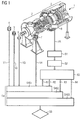
- Fig. 1 shows a flowchart, which represents the essential steps of an embodiment of a method according to the invention for monitoring the operation of a gas turbine.
- a gas turbine 1 is monitored, the structure is known per se and therefore only briefly explained.
- the gas turbine comprises a multi-stage axial compressor 2 with a plurality of pulleys and guide rows, wherein in the compressor a plurality of compressor stages with guide vanes and blades is formed.
- the vane adjusts the flow angle of the air in the compressor to the blade and compresses the blade and continues to pump the air.
- Connected to the axial compressor 2 in the turbine 3 is the combustion chamber, in which the corresponding fuel is burned with the aid of the air supplied via the compressor, as a result of which the turbine is driven.
- the sensor 4 is a temperature sensor which measures the ambient temperature and outputs a corresponding measurement signal V1.
- the sensor 5 is a pressure sensor which measures the air pressure of the environment and outputs a corresponding measurement signal V2.
- a humidity sensor is shown, which measures the humidity and outputs a corresponding measurement signal V3.
- a sensor 7 is predetermined, which measures the position of the adjustable guide vanes present there at the inlet of the compressor, wherein the position of the guide vanes in the gas turbine can be changed via a corresponding adjusting device.
- the measured value of the position of the vanes is in Fig. 1 denoted by V4.
- a pressure sensor 8 which dynamically measures the pressure at the compressor outlet in the form of a measuring signal V5.
- Dynamic here means that the temporal change of the sound pressure is determined with a corresponding sampling rate, so that the temporal behavior of the pressure is detected.
- a measurement is dynamic, in particular, when the sampling rate is in the kHz range and higher.
- the measured pressure signal is produced by the fact that in the individual compressor stages in operation, the compressor blade passes through the guide vane and thereby periodic pressure waves are generated in the compressed air, wherein the period of a pressure wave depends on the number of vanes and blades in the respective compressor stage.
- the detected dynamic pressure signal thus contains a plurality of periodic components due to the plurality of compressor stages.
- the signal V5 is first subjected to A / D conversion in step S1, and the digitized signal is finally used in step S2 to perform an FFT (Fast Fourier Transform) transformation for determining the frequency spectrum of the signal.
- FFT Fast Fourier Transform
- step S2 FFT transformation is so fine on the from the speed of the gas turbine and the number matched to the guide and rotor blades resulting frequencies that the individual frequencies can be clearly separated separated the compressor stages.
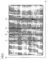
- the FFT transformation one obtains characteristic frequency bands with corresponding amplitudes of the individual frequencies.
- Such a frequency spectrum is exemplary in the diagram of Fig. 2 played.
- This diagram is also known as the Campbell diagram.
- the frequencies f are reproduced in the pressure signal and the time t along the ordinate.
- the amplitude of each frequency is in Fig. 2 color coded, due to the black and white representation of this color coding is not apparent.
- the color red is used for the display of high amplitudes.
- a region B is marked in which high amplitudes are present.
- certain operating variables of the turbine were changed. In particular, the load and the position of the vanes of the compressor has been changed.
- Each of the frequency bands F1 to F4 in this case represents a compressor stage of the axial compressor 2 of the gas turbine 1, ie each compressor stage is assigned a frequency band with a characteristic frequency when operating at a certain speed.
- step S3 of Fig. 1 now the evaluation of in Fig. 2 shown frequency bands, where appropriate, a correction is done with a corresponding model.
- RMS Root Mean Square
- This RMS value is a quantity well known to the person skilled in the art.
- step S3 one thus obtains for each compressor stage a characteristic RMS value, where in Fig. 1 For example, four RMS values R1 to R4 are reproduced for four compressor stages.
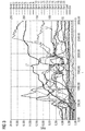
- Fig. 3 illustrates again in a corresponding diagram the time evolution of RMS values in a turbine with twenty characteristic frequency bands, which are each assigned to a compressor stage of the compressor of the gas turbine.
- the time in seconds is plotted along the abscissa and the corresponding RMS values of the individual bands along the ordinate.
- the diagram is also color-coded, with each band represented by a different color, but due to the black-and-white representation of the Fig. 3 not apparent.
- the individual frequency bands from band 1 to band 20 are reproduced here in the diagram in the legend on the right margin.
- the diagram contains the Fig. 3 the change in the load and the position of the vanes made on the turbine during operation.
- neural networks are used according to the invention.
- a neural model is preferably used based on radial basis functions, also known as the RBF network.
- the basic structure of such networks is sufficiently known from the prior art and will therefore not be explained in detail at this point.
- Such networks consist of an input layer and an output layer, and learn the parameters of radial basis functions, such as Gaussian functions, from the input variables in the input layer, thereby approximating the functional behavior and the distribution of the input quantities.
- a corresponding RBF network has been learned with the operating parameters and the corresponding RMS values of the compressor stage, the learning being performed based on measurements in normal operation of the gas turbine.
- the individual RBF networks produce as output a normalized value between 0 and 1 which is valid for a set of inputs, i. for at a given time operating parameters and corresponding RMS value, indicates the likelihood that such a combination of RMS value and operating parameters occurs in normal operation.
- This confidence value the more likely a normal operation will be.
- low confidence values mean that a malfunction in the corresponding compressor of the gas turbine has occurred with high probability.
- the correspondingly trained neural networks function as approximate data encapsulators and are used in Fig. 1 in step S4 with the individual operating parameters according to Measuring signals V1 to V4 and the RMS values R1 to R4 fed as input variables.
- the step S4 is divided into four substeps S401, S402 and S403 by way of example.
- step S401 the operating parameters and the RMS values R1 and R2 are supplied to the respective neural networks of the respective compressor stages.
- step S402 the RMS value R3 and in step S403 the RMS value R4 is supplied to the neural network of the corresponding compressor stage.
- a corresponding confidence value in the value range between 0 and 1 is now obtained for each neural network.
- step S5 For a confidence value between 0.5 and 1, for example, the statement that a normal operating state is present can be derived, whereas for confidence values less than 0 , 5 is diagnosed that a malfunction is present. These diagnostic characteristics are finally output in step S5.
- the operating parameters it is not necessary for the individual parameters to be uniquely related. Rather, any distribution of parameter combinations can be learned if sufficient operational data is available to train the neural models. For a high selectivity in recognizing unusual states, it is advisable to include all relevant parameters of the system as an input in the learning of the neural network.
- the trained data encapsulators are then used to monitor the gas turbine to a malfunction detect.
- the speed, the load, the Vorleitschaufel too, the air pressure, the ambient pressure, the humidity and the like are considered as parameters in learning or monitoring the gas turbine.
- the sizes put next to the energy amplitudes of the characteristic frequencies In addition, the ratio of the RMS values of characteristic frequencies to their harmonics in higher frequency bands can be included.
- the confidence values of the individual data capsulators can be combined.
- an overall confidence for the presence of normal operation can be determined.
- This can be done in particular on the basis of fuzzy rules or discrete rules expressing known relationships for the behavior and interaction of individual compressor stages.
- the quality and the status of the individual compressor stages of the axial compressor of a gas turbine can be diagnosed.
- the condition of the compressor can be diagnosed for the entire compressor, which reduces the overall cost of monitoring the operation of the gas turbine.
- the inventive method is easily adaptable to different gas turbines, by specifically learning the neural networks for the gas turbine first in training operation and then the monitoring of the gas turbine takes place on the basis of these learned networks.
- a fast and high-frequency monitoring of the entire compressor of a gas turbine during operation allows, in particular, long-term information over the term of the gas turbine are made possible.
Landscapes
- Engineering & Computer Science (AREA)
- Physics & Mathematics (AREA)
- Mechanical Engineering (AREA)
- General Engineering & Computer Science (AREA)
- Artificial Intelligence (AREA)
- Combustion & Propulsion (AREA)
- Chemical & Material Sciences (AREA)
- Evolutionary Computation (AREA)
- Mathematical Physics (AREA)
- General Physics & Mathematics (AREA)
- Automation & Control Theory (AREA)
- Control Of Positive-Displacement Air Blowers (AREA)
- Testing Of Engines (AREA)
Claims (12)
- Procédé d'analyse du fonctionnement du compresseur (2) à plusieurs étages d'une turbine (1) à gaz ayant une pluralité d'étages de compresseur et/ou de contrôle d'une turbine (1) à gaz,
dans lequel on fait l'apprentissage d'un réseau neuronal ou de plusieurs réseaux neuronaux sur la base du fonctionnement normal de la turbine (1) à gaz, dans lequel :- on mesure au moins un signal (V5) de pression dynamique par au moins un capteur (8) de pression dans ou sur le compresseur (2) de la turbine (1) à gaz, ainsi qu'un ou plusieurs paramètres (V1, V2, V3, V4) de fonctionnement de la turbine (1) à gaz par un ou par plusieurs autres capteurs (4, 5, 6, 7) alors que la turbine (1) à gaz fonctionne normalement et/ou on entre un signal (V5) de pression dynamique ainsi qu'un ou plusieurs paramètres (V1, V2, V3, V4) de fonctionnement de la turbine à gaz, qui ont été mesurés pendant un fonctionnement normal de la turbine (1) à gaz ;- on soumet le signal (V5) de pression dynamique à une analyse de fréquence, en déterminant ainsi un paramètre ou plusieurs paramètres du spectre de fréquence du signal (V5) de pression ;- sur la base du ou des paramètres (V1, V2, V3, V4) de fonctionnement mesurés et du ou des paramètres du spectre de fréquence du signal (V5) de pression, on fait l'apprentissage d'un réseau neuronal ou de plusieurs réseaux neuronaux, qui comprennent comme grandeurs d'entrée le ou les paramètres (V1, V2, V3, V4) de fonctionnement mesurés et le ou les paramètres du spectre de fréquence du signal (V5) de pression et comme grandeurs de sortie au moins une valeur caractéristique de diagnostic, qui représente une mesure de la probabilité que la turbine (1) à gaz soit en fonctionnement normal en fonction des grandeurs d'entrée,caractérisé en ce que
on détermine comme paramètre du spectre de fréquence pour chaque étage du compresseur une bande (F1, F2, F3, F4) de fréquence caractéristique à l'aide de la vitesse de rotation de la turbine à gaz et du nombre des aubes directrices et des aubes mobiles de l'étage de compresseur concerné, et, pour chaque bande de fréquence caractéristique, on calcule la proportion d'énergie, qui y est contenue, du signal (V5) de pression, notamment la valeur de root mean square et/ou le maximum d'amplitude et/ou plusieurs maximums d'amplitude voisins de raies de fréquence au sein de la bande (F1, F2, F3, F4) de fréquence caractéristique pour utilisation comme grandeurs d'entrée du réseau neuronal ou des réseaux neuronaux. - Procédé suivant la revendication 1,
dans lequel le réseau neuronal ou les réseaux neuronaux sont des réseaux de fonction à base radiale. - Procédé suivant la revendication 1 ou 2,
dans lequel au moins une valeur caractéristique de diagnostic est une valeur de confiance, qui est normée dans une plage de valeurs comprise entre 0 et 1 et qui représente la probabilité qu'une combinaison de paramètres de grandeurs d'entrée soit une combinaison de paramètres connue pendant un fonctionnement normal de la turbine (1) à gaz. - Procédé suivant l'une des revendications précédentes,
dans lequel on tient compte comme autre paramètre du spectre de fréquence, en outre, du rapport de la proportion d'énergie d'une bande (F1, F2, F3, F4) de fréquence caractéristique aux proportions d'énergie d'harmoniques de la bande (F1, F2, F3, F4) de fréquence caractéristique pour l'utilisation comme grandeurs d'entrée du réseau neuronal ou des réseaux neuronaux. - Procédé suivant l'une des revendications précédentes,
dans lequel, pour chaque étage du compresseur, on fait l'apprentissage d'un réseau neuronal, le réseau neuronal respectif comprenant comme grandeurs d'entrée des paramètres, appartenant à une bande (F1, F2, F3, F4) de fréquence caractéristique, du spectre de fréquence et chaque réseau neuronal ayant une valeur caractéristique de diagnostic comme grandeur de sortie,
cette valeur caractéristique de diagnostic représentant une probabilité de la présence du fonctionnement normal de cet étage de compresseur en fonction des grandeurs d'entrée. - Procédé suivant la revendication 5,
dans lequel, sur la base de règles définies à l'avance, notamment sur la base de règles floues, on détermine une valeur caractéristique de diagnostic global à partir des valeurs caractéristiques de diagnostics des étages de compresseurs respectifs. - Procédé suivant l'une des revendications précédentes,
dans lequel l'analyse de fréquence effectuée pour le signal (V5) de pression dynamique comprend une transformation de Fourier rapide. - Procédé suivant l'une des revendications précédentes,
dans lequel on mesure ou on entre comme paramètres (V1, V2, V3, V4) de fonctionnement un ou plusieurs des paramètres suivants :- la vitesse de rotation de la turbine (1) à gaz,- la charge de la turbine (1) à gaz,- la pression ambiante,- la température ambiante,- l'humidité de l'air,- la position des aubes directrices du compresseur (2) de la turbine (1) à gaz. - Procédé suivant la revendication 8,
dans lequel les paramètres (V1, V2, V3, V4) de fonctionnement mesurés et le signal (V5) de pression dynamique proviennent d'un fonctionnement normal, dans lequel la turbine (1) à gaz fonctionne à une vitesse de rotation fixe pour des charges différentes et/ou des positions différentes des aubes directrices. - Procédé suivant l'une des revendications 1 à 9,
dans lequel on émet un signal d'alerte si une valeur caractéristique de diagnostic ou plusieurs des valeurs caractéristiques de diagnostic se trouvent en dehors d'une plage de valeurs définie à l'avance. - Dispositif pour effectuer le procédé suivant l'une des revendications 1 à 10,
comprenant :- au moins un capteur (8) de pression pour mesurer au moins un signal (V5) de pression dynamique dans ou sur le compresseur (2) de la turbine (1) à gaz, ainsi qu'un ou plusieurs autres capteurs de mesure d'un ou de plusieurs paramètres (V1, V2, V3, V4) de fonctionnement de la turbine (1) à gaz, alors que la turbine (1) à gaz fonctionne.- un dispositif d'analyse de fréquence, par lequel on peut soumettre le signal (V5) de pression dynamique à une analyse de fréquence, par laquelle on détermine un paramètre ou plusieurs paramètres du spectre de fréquence du signal (V5) de pression,- le réseau neuronal ou les réseaux neuronaux ayant subi un apprentissage auxquels on peut envoyer comme grandeurs d'entrée le ou les paramètres (V1, V2, V3, V4) de fonctionnement mesurés et le ou les paramètres du spectre de fréquence du signal (V5) de pression et qui, à partir des grandeurs d'entrée, peuvent émettre au moins une valeur caractéristique de diagnostic, qui représente une mesure de la probabilité que la turbine (1) à gaz est en fonctionnement normal en fonction des grandeurs d'entrée,caractérisé en ce que
comme paramètres du spectre de fréquence pour chaque étage du compresseur, une bande (F1, F2, F3, F4) de fréquence caractéristique est utilisée à l'aide de la vitesse de rotation de la turbine à gaz et du nombre des aubes directrices et des aubes mobiles de l'étage de compresseur concerné et pour chaque bande de fréquence caractéristique est utilisée la proportion d'énergie, qui y est contenue, du signal (V5) de fréquence, notamment la valeur de root mean square et/ou le maximum d'amplitude et/ou plusieurs maximums d'amplitude voisins de raies de fréquence au sein de la bande (F1, F2, F3, F4) de fréquence caractéristique pour l'utilisation comme grandeurs d'entrée du réseau neuronal ou des réseaux neuronaux. - Turbine à gaz,
comprenant un dispositif suivant la revendication 11.
Priority Applications (1)
| Application Number | Priority Date | Filing Date | Title |
|---|---|---|---|
| EP08804472.2A EP2201430B1 (fr) | 2007-10-26 | 2008-09-19 | Procédé d'analyse du fonctionnement d'une turbine à gaz |
Applications Claiming Priority (3)
| Application Number | Priority Date | Filing Date | Title |
|---|---|---|---|
| EP07021041A EP2053475A1 (fr) | 2007-10-26 | 2007-10-26 | Procédé d'analyse du fonctionnement d'une turbine à gaz |
| EP08804472.2A EP2201430B1 (fr) | 2007-10-26 | 2008-09-19 | Procédé d'analyse du fonctionnement d'une turbine à gaz |
| PCT/EP2008/062538 WO2009053183A2 (fr) | 2007-10-26 | 2008-09-19 | Procédé d'analyse du fonctionnement d'une turbine à gaz |
Publications (2)
| Publication Number | Publication Date |
|---|---|
| EP2201430A2 EP2201430A2 (fr) | 2010-06-30 |
| EP2201430B1 true EP2201430B1 (fr) | 2016-04-20 |
Family
ID=39431230
Family Applications (2)
| Application Number | Title | Priority Date | Filing Date |
|---|---|---|---|
| EP07021041A Withdrawn EP2053475A1 (fr) | 2007-10-26 | 2007-10-26 | Procédé d'analyse du fonctionnement d'une turbine à gaz |
| EP08804472.2A Active EP2201430B1 (fr) | 2007-10-26 | 2008-09-19 | Procédé d'analyse du fonctionnement d'une turbine à gaz |
Family Applications Before (1)
| Application Number | Title | Priority Date | Filing Date |
|---|---|---|---|
| EP07021041A Withdrawn EP2053475A1 (fr) | 2007-10-26 | 2007-10-26 | Procédé d'analyse du fonctionnement d'une turbine à gaz |
Country Status (8)
| Country | Link |
|---|---|
| US (1) | US8396689B2 (fr) |
| EP (2) | EP2053475A1 (fr) |
| JP (1) | JP5393693B2 (fr) |
| CN (1) | CN101836168B (fr) |
| CA (1) | CA2703586C (fr) |
| RU (1) | RU2480806C2 (fr) |
| TW (1) | TWI370201B (fr) |
| WO (1) | WO2009053183A2 (fr) |
Cited By (1)
| Publication number | Priority date | Publication date | Assignee | Title |
|---|---|---|---|---|
| DE102022205661A1 (de) | 2022-06-02 | 2023-12-07 | Siemens Energy Global GmbH & Co. KG | Gasturbine mit Schwingungssensoren |
Families Citing this family (40)
| Publication number | Priority date | Publication date | Assignee | Title |
|---|---|---|---|---|
| US10089443B2 (en) | 2012-05-15 | 2018-10-02 | Baxter International Inc. | Home medical device systems and methods for therapy prescription and tracking, servicing and inventory |
| US8437941B2 (en) * | 2009-05-08 | 2013-05-07 | Gas Turbine Efficiency Sweden Ab | Automated tuning of gas turbine combustion systems |
| US9671797B2 (en) | 2009-05-08 | 2017-06-06 | Gas Turbine Efficiency Sweden Ab | Optimization of gas turbine combustion systems low load performance on simple cycle and heat recovery steam generator applications |
| US9267443B2 (en) | 2009-05-08 | 2016-02-23 | Gas Turbine Efficiency Sweden Ab | Automated tuning of gas turbine combustion systems |
| US9354618B2 (en) | 2009-05-08 | 2016-05-31 | Gas Turbine Efficiency Sweden Ab | Automated tuning of multiple fuel gas turbine combustion systems |
| US8135568B2 (en) | 2010-06-25 | 2012-03-13 | General Electric Company | Turbomachine airfoil life management system and method |
| CN102063109B (zh) * | 2010-11-29 | 2012-09-05 | 株洲南车时代电气股份有限公司 | 一种基于神经网络的地铁列车故障诊断装置及其方法 |
| WO2012076427A1 (fr) | 2010-12-09 | 2012-06-14 | Basf Se | Procédé et dispositif pour la surveillance d'une turbomachine, basée sur un modèle |
| ITCO20120008A1 (it) * | 2012-03-01 | 2013-09-02 | Nuovo Pignone Srl | Metodo e sistema per monitorare la condizione di un gruppo di impianti |
| US9212946B2 (en) * | 2012-06-08 | 2015-12-15 | General Electric Company | Campbell diagram displays and methods and systems for implementing same |
| EP2706422B1 (fr) | 2012-09-11 | 2016-07-27 | Siemens Aktiengesellschaft | Procédé de surveillance assistée par ordinateur du fonctionnement d'un système technique, en particulier d'une installation de production d'énergie électrique |
| US9500563B2 (en) * | 2013-12-05 | 2016-11-22 | General Electric Company | System and method for detecting an at-fault combustor |
| US20150159867A1 (en) * | 2013-12-05 | 2015-06-11 | General Electric Company | System and Method for Assessing Combustor Health During Operation |
| DE102013226049A1 (de) * | 2013-12-16 | 2015-06-18 | Siemens Aktiengesellschaft | Vorrichtung sowie Verfahren zum Erfassen des aktuellen Schädigungszustandes einer Maschine |
| EP2996001A1 (fr) * | 2014-09-10 | 2016-03-16 | Siemens Aktiengesellschaft | Procédé d'analyse assisté par ordinateur d'un ensemble de données provenant d'observations |
| EP3064744B1 (fr) | 2015-03-04 | 2017-11-22 | MTU Aero Engines GmbH | Diagnostic de groupes turbomoteur |
| US20160363127A1 (en) * | 2015-06-09 | 2016-12-15 | General Electric Company | Systems and methods for monitoring a compressor |
| WO2017058832A1 (fr) | 2015-09-28 | 2017-04-06 | Schlumberger Technology Corporation | Systèmes de surveillance et de commande de brûleur |
| US10809156B2 (en) * | 2016-02-15 | 2020-10-20 | General Electric Company | Automated system and method for generating engine test cell analytics and diagnostics |
| US10983507B2 (en) | 2016-05-09 | 2021-04-20 | Strong Force Iot Portfolio 2016, Llc | Method for data collection and frequency analysis with self-organization functionality |
| US11327475B2 (en) | 2016-05-09 | 2022-05-10 | Strong Force Iot Portfolio 2016, Llc | Methods and systems for intelligent collection and analysis of vehicle data |
| KR102000416B1 (ko) | 2016-05-09 | 2019-07-15 | 스트롱 포스 아이오티 포트폴리오 2016, 엘엘씨 | 산업용 사물 인터넷을 위한 방법들 및 시스템들 |
| US11774944B2 (en) | 2016-05-09 | 2023-10-03 | Strong Force Iot Portfolio 2016, Llc | Methods and systems for the industrial internet of things |
| US11646808B2 (en) | 2016-05-09 | 2023-05-09 | Strong Force Iot Portfolio 2016, Llc | Methods and systems for adaption of data storage and communication in an internet of things downstream oil and gas environment |
| US10724443B2 (en) | 2016-05-24 | 2020-07-28 | General Electric Company | Turbine engine and method of operating |
| US11686212B2 (en) | 2016-05-24 | 2023-06-27 | General Electric Company | Turbine engine and method of cooling |
| US11237546B2 (en) | 2016-06-15 | 2022-02-01 | Strong Force loT Portfolio 2016, LLC | Method and system of modifying a data collection trajectory for vehicles |
| CA3072045A1 (fr) | 2017-08-02 | 2019-02-07 | Strong Force Iot Portfolio 2016, Llc | Procedes et systemes de detection dans un environnement industriel de collecte de donnees d'internet des objets avec de grands ensembles de donnees |
| US10908602B2 (en) | 2017-08-02 | 2021-02-02 | Strong Force Iot Portfolio 2016, Llc | Systems and methods for network-sensitive data collection |
| JP7445928B2 (ja) * | 2018-05-07 | 2024-03-08 | ストロング フォース アイオーティ ポートフォリオ 2016,エルエルシー | 産業用のモノのインターネットを利用した解析及びメンテナンスのための機械信号のデータ収集、学習、ストリーミングのための方法並びにシステム |
| CN109960867B (zh) * | 2019-03-21 | 2022-09-20 | 哈尔滨工业大学 | 一种基于惯性回转中心调控最优化及智能学习的大型高速回转装备多级零部件选配方法 |
| US20200364498A1 (en) * | 2019-05-15 | 2020-11-19 | Schlumberger Technology Corporation | Autonomous burner |
| GB201908496D0 (en) * | 2019-06-13 | 2019-07-31 | Rolls Royce Plc | Computer-implemented methods for determining compressor operability |
| GB201908497D0 (en) * | 2019-06-13 | 2019-07-31 | Rolls Royce Plc | Computer-implemented methods for controlling a gas turbine engine |
| GB201908494D0 (en) | 2019-06-13 | 2019-07-31 | Rolls Royce Plc | Computer-implemented methods for training a machine learning algorithm |
| US11340592B2 (en) * | 2019-07-22 | 2022-05-24 | Rockwell Automation Technologies, Inc. | Industrial control system with machine learning for compressors |
| RU2725299C1 (ru) * | 2020-01-29 | 2020-06-30 | Федеральное государственное унитарное предприятие "Центральный институт авиационного моторостроения имени П.И. Баранова" | Способ оценки технического состояния лопаток турбины газотурбинного двигателя |
| JP7294222B2 (ja) * | 2020-04-16 | 2023-06-20 | トヨタ自動車株式会社 | 異音評価システムおよび異音評価方法 |
| US11342932B2 (en) * | 2020-05-13 | 2022-05-24 | Computational Systems, Inc. | Machine spectral data compression |
| CN111965981B (zh) * | 2020-09-07 | 2022-02-22 | 厦门大学 | 一种航空发动机强化学习控制方法及系统 |
Family Cites Families (13)
| Publication number | Priority date | Publication date | Assignee | Title |
|---|---|---|---|---|
| JPH0692914B2 (ja) * | 1989-04-14 | 1994-11-16 | 株式会社日立製作所 | 機器/設備の状態診断システム |
| US7010459B2 (en) | 1999-06-25 | 2006-03-07 | Rosemount Inc. | Process device diagnostics using process variable sensor signal |
| EP1299783A2 (fr) * | 2000-06-19 | 2003-04-09 | The Dow Chemical Company | Systeme de diagnostique d'equipement rotatif et unite de commande adaptive |
| GB0016561D0 (en) * | 2000-07-05 | 2000-08-23 | Rolls Royce Plc | Health monitoring |
| JP4638005B2 (ja) * | 2000-08-28 | 2011-02-23 | ルネサスエレクトロニクス株式会社 | 半導体装置 |
| US7797062B2 (en) * | 2001-08-10 | 2010-09-14 | Rockwell Automation Technologies, Inc. | System and method for dynamic multi-objective optimization of machine selection, integration and utilization |
| JP3708041B2 (ja) * | 2001-11-16 | 2005-10-19 | 株式会社東芝 | 回転機械の振動診断方法及び装置 |
| MXPA05003199A (es) * | 2002-09-26 | 2005-07-05 | Siemens Ag | Dispositivo y procedimiento para vigilar una instalacion tecnica que abarca varios sistemas, en particular una instalacion de central electrica. |
| US7027953B2 (en) * | 2002-12-30 | 2006-04-11 | Rsl Electronics Ltd. | Method and system for diagnostics and prognostics of a mechanical system |
| JP2005155590A (ja) * | 2003-10-30 | 2005-06-16 | Mitsubishi Heavy Ind Ltd | ガスタービン制御装置、ガスタービンシステム、ガスタービンの制御方法 |
| DE102006048730A1 (de) * | 2005-11-03 | 2007-05-31 | Volkswagen Ag | Verfahren und Vorrichtung zur Bestimmung der Messgenauigkeit einer Messeinrichtung |
| CN2866857Y (zh) * | 2005-12-08 | 2007-02-07 | 中国南方航空动力机械公司 | 燃气轮机发电机组控制装置 |
| DE102006004516B3 (de) * | 2006-02-01 | 2007-03-08 | Mtu Friedrichshafen Gmbh | Bayes-Netz zur Steuerung und Regelung einer Brennkraftmaschine |
-
2007
- 2007-10-26 EP EP07021041A patent/EP2053475A1/fr not_active Withdrawn
-
2008
- 2008-09-19 RU RU2010121150/08A patent/RU2480806C2/ru active
- 2008-09-19 CA CA2703586A patent/CA2703586C/fr active Active
- 2008-09-19 US US12/739,782 patent/US8396689B2/en active Active
- 2008-09-19 JP JP2010530378A patent/JP5393693B2/ja active Active
- 2008-09-19 EP EP08804472.2A patent/EP2201430B1/fr active Active
- 2008-09-19 CN CN2008801132640A patent/CN101836168B/zh active Active
- 2008-09-19 WO PCT/EP2008/062538 patent/WO2009053183A2/fr active Application Filing
- 2008-10-24 TW TW097140770A patent/TWI370201B/zh active
Cited By (1)
| Publication number | Priority date | Publication date | Assignee | Title |
|---|---|---|---|---|
| DE102022205661A1 (de) | 2022-06-02 | 2023-12-07 | Siemens Energy Global GmbH & Co. KG | Gasturbine mit Schwingungssensoren |
Also Published As
| Publication number | Publication date |
|---|---|
| WO2009053183A2 (fr) | 2009-04-30 |
| JP2011501170A (ja) | 2011-01-06 |
| RU2010121150A (ru) | 2011-12-10 |
| CN101836168B (zh) | 2013-03-06 |
| US20100262401A1 (en) | 2010-10-14 |
| EP2201430A2 (fr) | 2010-06-30 |
| RU2480806C2 (ru) | 2013-04-27 |
| CA2703586C (fr) | 2015-08-04 |
| CA2703586A1 (fr) | 2009-04-30 |
| WO2009053183A3 (fr) | 2009-06-11 |
| US8396689B2 (en) | 2013-03-12 |
| TWI370201B (en) | 2012-08-11 |
| EP2053475A1 (fr) | 2009-04-29 |
| CN101836168A (zh) | 2010-09-15 |
| JP5393693B2 (ja) | 2014-01-22 |
| TW200928079A (en) | 2009-07-01 |
Similar Documents
| Publication | Publication Date | Title |
|---|---|---|
| EP2201430B1 (fr) | Procédé d'analyse du fonctionnement d'une turbine à gaz | |
| EP2404059B1 (fr) | Procédé de surveillance d'éoliennes | |
| EP1499825B1 (fr) | Systeme et procede de diagnostique pour une vanne | |
| EP2169221B1 (fr) | Procédé de surveillance d'un engrenage d'éolienne | |
| EP1688671B2 (fr) | Méthode de protection et système de contrôle pour turbine à gaz | |
| DE102010016615A1 (de) | Fehlererkennung und Schutz von mehrstufigen Verdichtern | |
| DE102014117270A1 (de) | System und Verfahren zur Detektion einer fehlerhaften Brennkammer | |
| DE102011056644A1 (de) | Verfahren und System zur Verdichterzustandsüberwachung | |
| EP3058430B1 (fr) | Dispositif et procédé permettant de détecter l'état d'endommagement instantané d'une machine | |
| EP1476733B1 (fr) | Procede et dispositif pour la detection d'une action mecanique impulsionnelle sur une partie d'installation | |
| EP2294287A2 (fr) | Procédé et dispositif de détection de fissures sur des aubes mobiles d'un compresseur | |
| EP1198739B1 (fr) | Procede et systeme de diagnostic pour une installation technique | |
| EP3589843B1 (fr) | Procédé et dispositif pour détecter un indicateur pour la prédiction d'une instabilité dans un compresseur, et usage correspondant | |
| DE102010009941A1 (de) | Verfahren zum Überwachen von Windturbinen | |
| DE102010005525A1 (de) | Verfahren zur Zustandsüberwachung einer Maschine und Überwachungseinrichtung hierfür | |
| EP3475536B1 (fr) | Procédé de reconnaissance de dégâts dans une turbine à gaz en fonctionnement | |
| DE19843615C2 (de) | Vorrichtung und Verfahren zur Diagnose von Verbrennungsantrieben | |
| EP1014054B1 (fr) | Procédé de contrôle des machines rotatives se basant sur un model diagnostique des vibrations | |
| DE60319245T2 (de) | Verfahren und einrichtung zur bestimmung des zustands einer turbinenschaufel und zur verwendung der gesammelten informationen zur schätzung der lebensdauer der schaufel | |
| EP1792242B1 (fr) | Procede et dispositif pour determiner un etat defectueux dans un compresseur rotatif | |
| DE102011055826A1 (de) | Systeme und Verfahren zum Schutz gegen Pumpvorläufer | |
| DE102004022748B4 (de) | System und Verfahren zur automatischen Ursachenanalyse von anlagenweiten Störungen in einem technischen Prozess | |
| EP2811279B1 (fr) | Procédé et dispositif de validation d'un signal électrique | |
| EP1363248A1 (fr) | Méthode d'identification de la condition d'un élement sous contrainte mécanique, système informatique pour mettre en oeuvre la méthode, programme informatique mun de moyens de programmation et produit de programme informatique | |
| DE102022205661A1 (de) | Gasturbine mit Schwingungssensoren |
Legal Events
| Date | Code | Title | Description |
|---|---|---|---|
| PUAI | Public reference made under article 153(3) epc to a published international application that has entered the european phase |
Free format text: ORIGINAL CODE: 0009012 |
|
| 17P | Request for examination filed |
Effective date: 20100329 |
|
| AK | Designated contracting states |
Kind code of ref document: A2 Designated state(s): AT BE BG CH CY CZ DE DK EE ES FI FR GB GR HR HU IE IS IT LI LT LU LV MC MT NL NO PL PT RO SE SI SK TR |
|
| AX | Request for extension of the european patent |
Extension state: AL BA MK RS |
|
| 17Q | First examination report despatched |
Effective date: 20111117 |
|
| DAX | Request for extension of the european patent (deleted) | ||
| RAP1 | Party data changed (applicant data changed or rights of an application transferred) |
Owner name: SIEMENS AKTIENGESELLSCHAFT |
|
| GRAP | Despatch of communication of intention to grant a patent |
Free format text: ORIGINAL CODE: EPIDOSNIGR1 |
|
| INTG | Intention to grant announced |
Effective date: 20151119 |
|
| GRAS | Grant fee paid |
Free format text: ORIGINAL CODE: EPIDOSNIGR3 |
|
| GRAA | (expected) grant |
Free format text: ORIGINAL CODE: 0009210 |
|
| AK | Designated contracting states |
Kind code of ref document: B1 Designated state(s): AT BE BG CH CY CZ DE DK EE ES FI FR GB GR HR HU IE IS IT LI LT LU LV MC MT NL NO PL PT RO SE SI SK TR |
|
| REG | Reference to a national code |
Ref country code: GB Ref legal event code: FG4D Free format text: NOT ENGLISH |
|
| REG | Reference to a national code |
Ref country code: CH Ref legal event code: EP |
|
| REG | Reference to a national code |
Ref country code: AT Ref legal event code: REF Ref document number: 793089 Country of ref document: AT Kind code of ref document: T Effective date: 20160515 |
|
| REG | Reference to a national code |
Ref country code: IE Ref legal event code: FG4D Free format text: LANGUAGE OF EP DOCUMENT: GERMAN |
|
| REG | Reference to a national code |
Ref country code: CH Ref legal event code: NV Representative=s name: SIEMENS SCHWEIZ AG, CH |
|
| REG | Reference to a national code |
Ref country code: DE Ref legal event code: R096 Ref document number: 502008014121 Country of ref document: DE |
|
| REG | Reference to a national code |
Ref country code: SE Ref legal event code: TRGR |
|
| REG | Reference to a national code |
Ref country code: LT Ref legal event code: MG4D |
|
| REG | Reference to a national code |
Ref country code: FR Ref legal event code: PLFP Year of fee payment: 9 |
|
| REG | Reference to a national code |
Ref country code: NL Ref legal event code: MP Effective date: 20160420 |
|
| PG25 | Lapsed in a contracting state [announced via postgrant information from national office to epo] |
Ref country code: LT Free format text: LAPSE BECAUSE OF FAILURE TO SUBMIT A TRANSLATION OF THE DESCRIPTION OR TO PAY THE FEE WITHIN THE PRESCRIBED TIME-LIMIT Effective date: 20160420 Ref country code: NL Free format text: LAPSE BECAUSE OF FAILURE TO SUBMIT A TRANSLATION OF THE DESCRIPTION OR TO PAY THE FEE WITHIN THE PRESCRIBED TIME-LIMIT Effective date: 20160420 Ref country code: NO Free format text: LAPSE BECAUSE OF FAILURE TO SUBMIT A TRANSLATION OF THE DESCRIPTION OR TO PAY THE FEE WITHIN THE PRESCRIBED TIME-LIMIT Effective date: 20160720 Ref country code: FI Free format text: LAPSE BECAUSE OF FAILURE TO SUBMIT A TRANSLATION OF THE DESCRIPTION OR TO PAY THE FEE WITHIN THE PRESCRIBED TIME-LIMIT Effective date: 20160420 Ref country code: PL Free format text: LAPSE BECAUSE OF FAILURE TO SUBMIT A TRANSLATION OF THE DESCRIPTION OR TO PAY THE FEE WITHIN THE PRESCRIBED TIME-LIMIT Effective date: 20160420 |
|
| PG25 | Lapsed in a contracting state [announced via postgrant information from national office to epo] |
Ref country code: LV Free format text: LAPSE BECAUSE OF FAILURE TO SUBMIT A TRANSLATION OF THE DESCRIPTION OR TO PAY THE FEE WITHIN THE PRESCRIBED TIME-LIMIT Effective date: 20160420 Ref country code: ES Free format text: LAPSE BECAUSE OF FAILURE TO SUBMIT A TRANSLATION OF THE DESCRIPTION OR TO PAY THE FEE WITHIN THE PRESCRIBED TIME-LIMIT Effective date: 20160420 Ref country code: HR Free format text: LAPSE BECAUSE OF FAILURE TO SUBMIT A TRANSLATION OF THE DESCRIPTION OR TO PAY THE FEE WITHIN THE PRESCRIBED TIME-LIMIT Effective date: 20160420 Ref country code: PT Free format text: LAPSE BECAUSE OF FAILURE TO SUBMIT A TRANSLATION OF THE DESCRIPTION OR TO PAY THE FEE WITHIN THE PRESCRIBED TIME-LIMIT Effective date: 20160822 Ref country code: GR Free format text: LAPSE BECAUSE OF FAILURE TO SUBMIT A TRANSLATION OF THE DESCRIPTION OR TO PAY THE FEE WITHIN THE PRESCRIBED TIME-LIMIT Effective date: 20160721 |
|
| REG | Reference to a national code |
Ref country code: DE Ref legal event code: R097 Ref document number: 502008014121 Country of ref document: DE |
|
| PG25 | Lapsed in a contracting state [announced via postgrant information from national office to epo] |
Ref country code: SK Free format text: LAPSE BECAUSE OF FAILURE TO SUBMIT A TRANSLATION OF THE DESCRIPTION OR TO PAY THE FEE WITHIN THE PRESCRIBED TIME-LIMIT Effective date: 20160420 Ref country code: EE Free format text: LAPSE BECAUSE OF FAILURE TO SUBMIT A TRANSLATION OF THE DESCRIPTION OR TO PAY THE FEE WITHIN THE PRESCRIBED TIME-LIMIT Effective date: 20160420 Ref country code: CZ Free format text: LAPSE BECAUSE OF FAILURE TO SUBMIT A TRANSLATION OF THE DESCRIPTION OR TO PAY THE FEE WITHIN THE PRESCRIBED TIME-LIMIT Effective date: 20160420 Ref country code: RO Free format text: LAPSE BECAUSE OF FAILURE TO SUBMIT A TRANSLATION OF THE DESCRIPTION OR TO PAY THE FEE WITHIN THE PRESCRIBED TIME-LIMIT Effective date: 20160420 Ref country code: DK Free format text: LAPSE BECAUSE OF FAILURE TO SUBMIT A TRANSLATION OF THE DESCRIPTION OR TO PAY THE FEE WITHIN THE PRESCRIBED TIME-LIMIT Effective date: 20160420 |
|
| PLBE | No opposition filed within time limit |
Free format text: ORIGINAL CODE: 0009261 |
|
| STAA | Information on the status of an ep patent application or granted ep patent |
Free format text: STATUS: NO OPPOSITION FILED WITHIN TIME LIMIT |
|
| PG25 | Lapsed in a contracting state [announced via postgrant information from national office to epo] |
Ref country code: BE Free format text: LAPSE BECAUSE OF NON-PAYMENT OF DUE FEES Effective date: 20160930 |
|
| 26N | No opposition filed |
Effective date: 20170123 |
|
| PG25 | Lapsed in a contracting state [announced via postgrant information from national office to epo] |
Ref country code: MC Free format text: LAPSE BECAUSE OF FAILURE TO SUBMIT A TRANSLATION OF THE DESCRIPTION OR TO PAY THE FEE WITHIN THE PRESCRIBED TIME-LIMIT Effective date: 20160420 |
|
| PG25 | Lapsed in a contracting state [announced via postgrant information from national office to epo] |
Ref country code: SI Free format text: LAPSE BECAUSE OF FAILURE TO SUBMIT A TRANSLATION OF THE DESCRIPTION OR TO PAY THE FEE WITHIN THE PRESCRIBED TIME-LIMIT Effective date: 20160420 |
|
| REG | Reference to a national code |
Ref country code: IE Ref legal event code: MM4A |
|
| PG25 | Lapsed in a contracting state [announced via postgrant information from national office to epo] |
Ref country code: IE Free format text: LAPSE BECAUSE OF NON-PAYMENT OF DUE FEES Effective date: 20160919 |
|
| PG25 | Lapsed in a contracting state [announced via postgrant information from national office to epo] |
Ref country code: LU Free format text: LAPSE BECAUSE OF NON-PAYMENT OF DUE FEES Effective date: 20160919 |
|
| REG | Reference to a national code |
Ref country code: FR Ref legal event code: PLFP Year of fee payment: 10 |
|
| REG | Reference to a national code |
Ref country code: CH Ref legal event code: PCOW Free format text: NEW ADDRESS: WERNER-VON-SIEMENS-STRASSE 1, 80333 MUENCHEN (DE) |
|
| REG | Reference to a national code |
Ref country code: BE Ref legal event code: MM Effective date: 20160930 |
|
| PG25 | Lapsed in a contracting state [announced via postgrant information from national office to epo] |
Ref country code: CY Free format text: LAPSE BECAUSE OF FAILURE TO SUBMIT A TRANSLATION OF THE DESCRIPTION OR TO PAY THE FEE WITHIN THE PRESCRIBED TIME-LIMIT Effective date: 20160420 Ref country code: HU Free format text: LAPSE BECAUSE OF FAILURE TO SUBMIT A TRANSLATION OF THE DESCRIPTION OR TO PAY THE FEE WITHIN THE PRESCRIBED TIME-LIMIT; INVALID AB INITIO Effective date: 20080919 |
|
| PG25 | Lapsed in a contracting state [announced via postgrant information from national office to epo] |
Ref country code: MT Free format text: LAPSE BECAUSE OF FAILURE TO SUBMIT A TRANSLATION OF THE DESCRIPTION OR TO PAY THE FEE WITHIN THE PRESCRIBED TIME-LIMIT Effective date: 20160420 Ref country code: IS Free format text: LAPSE BECAUSE OF FAILURE TO SUBMIT A TRANSLATION OF THE DESCRIPTION OR TO PAY THE FEE WITHIN THE PRESCRIBED TIME-LIMIT Effective date: 20160420 |
|
| PG25 | Lapsed in a contracting state [announced via postgrant information from national office to epo] |
Ref country code: BG Free format text: LAPSE BECAUSE OF FAILURE TO SUBMIT A TRANSLATION OF THE DESCRIPTION OR TO PAY THE FEE WITHIN THE PRESCRIBED TIME-LIMIT Effective date: 20160420 |
|
| REG | Reference to a national code |
Ref country code: FR Ref legal event code: PLFP Year of fee payment: 11 |
|
| REG | Reference to a national code |
Ref country code: DE Ref legal event code: R081 Ref document number: 502008014121 Country of ref document: DE Owner name: SIEMENS ENERGY GLOBAL GMBH & CO. KG, DE Free format text: FORMER OWNER: SIEMENS AKTIENGESELLSCHAFT, 80333 MUENCHEN, DE |
|
| REG | Reference to a national code |
Ref country code: GB Ref legal event code: 732E Free format text: REGISTERED BETWEEN 20220908 AND 20220914 |
|
| REG | Reference to a national code |
Ref country code: AT Ref legal event code: PC Ref document number: 793089 Country of ref document: AT Kind code of ref document: T Owner name: SIEMENS ENERGY GLOBAL GMBH & CO. KG, DE Effective date: 20221018 |
|
| PGFP | Annual fee paid to national office [announced via postgrant information from national office to epo] |
Ref country code: TR Payment date: 20230829 Year of fee payment: 16 Ref country code: IT Payment date: 20230920 Year of fee payment: 16 Ref country code: GB Payment date: 20230926 Year of fee payment: 16 Ref country code: AT Payment date: 20230919 Year of fee payment: 16 |
|
| PGFP | Annual fee paid to national office [announced via postgrant information from national office to epo] |
Ref country code: SE Payment date: 20230926 Year of fee payment: 16 Ref country code: FR Payment date: 20230926 Year of fee payment: 16 Ref country code: DE Payment date: 20230928 Year of fee payment: 16 |
|
| P01 | Opt-out of the competence of the unified patent court (upc) registered |
Effective date: 20231222 |
|
| PGFP | Annual fee paid to national office [announced via postgrant information from national office to epo] |
Ref country code: CH Payment date: 20231001 Year of fee payment: 16 |