EP2200740B1 - Mikrofluidische verfahren - Google Patents
Mikrofluidische verfahren Download PDFInfo
- Publication number
- EP2200740B1 EP2200740B1 EP08806758.2A EP08806758A EP2200740B1 EP 2200740 B1 EP2200740 B1 EP 2200740B1 EP 08806758 A EP08806758 A EP 08806758A EP 2200740 B1 EP2200740 B1 EP 2200740B1
- Authority
- EP
- European Patent Office
- Prior art keywords
- stream
- droplet
- contents
- fluid
- emulsion
- Prior art date
- Legal status (The legal status is an assumption and is not a legal conclusion. Google has not performed a legal analysis and makes no representation as to the accuracy of the status listed.)
- Active
Links
Images



Classifications
-
- B—PERFORMING OPERATIONS; TRANSPORTING
- B01—PHYSICAL OR CHEMICAL PROCESSES OR APPARATUS IN GENERAL
- B01J—CHEMICAL OR PHYSICAL PROCESSES, e.g. CATALYSIS OR COLLOID CHEMISTRY; THEIR RELEVANT APPARATUS
- B01J19/00—Chemical, physical or physico-chemical processes in general; Their relevant apparatus
- B01J19/0093—Microreactors, e.g. miniaturised or microfabricated reactors
-
- B—PERFORMING OPERATIONS; TRANSPORTING
- B01—PHYSICAL OR CHEMICAL PROCESSES OR APPARATUS IN GENERAL
- B01L—CHEMICAL OR PHYSICAL LABORATORY APPARATUS FOR GENERAL USE
- B01L3/00—Containers or dishes for laboratory use, e.g. laboratory glassware; Droppers
- B01L3/50—Containers for the purpose of retaining a material to be analysed, e.g. test tubes
- B01L3/502—Containers for the purpose of retaining a material to be analysed, e.g. test tubes with fluid transport, e.g. in multi-compartment structures
- B01L3/5027—Containers for the purpose of retaining a material to be analysed, e.g. test tubes with fluid transport, e.g. in multi-compartment structures by integrated microfluidic structures, i.e. dimensions of channels and chambers are such that surface tension forces are important, e.g. lab-on-a-chip
- B01L3/502769—Containers for the purpose of retaining a material to be analysed, e.g. test tubes with fluid transport, e.g. in multi-compartment structures by integrated microfluidic structures, i.e. dimensions of channels and chambers are such that surface tension forces are important, e.g. lab-on-a-chip characterised by multiphase flow arrangements
- B01L3/502784—Containers for the purpose of retaining a material to be analysed, e.g. test tubes with fluid transport, e.g. in multi-compartment structures by integrated microfluidic structures, i.e. dimensions of channels and chambers are such that surface tension forces are important, e.g. lab-on-a-chip characterised by multiphase flow arrangements specially adapted for droplet or plug flow, e.g. digital microfluidics
-
- B—PERFORMING OPERATIONS; TRANSPORTING
- B01—PHYSICAL OR CHEMICAL PROCESSES OR APPARATUS IN GENERAL
- B01J—CHEMICAL OR PHYSICAL PROCESSES, e.g. CATALYSIS OR COLLOID CHEMISTRY; THEIR RELEVANT APPARATUS
- B01J2219/00—Chemical, physical or physico-chemical processes in general; Their relevant apparatus
- B01J2219/00274—Sequential or parallel reactions; Apparatus and devices for combinatorial chemistry or for making arrays; Chemical library technology
- B01J2219/00277—Apparatus
- B01J2219/0054—Means for coding or tagging the apparatus or the reagents
- B01J2219/00572—Chemical means
- B01J2219/00576—Chemical means fluorophore
-
- B—PERFORMING OPERATIONS; TRANSPORTING
- B01—PHYSICAL OR CHEMICAL PROCESSES OR APPARATUS IN GENERAL
- B01J—CHEMICAL OR PHYSICAL PROCESSES, e.g. CATALYSIS OR COLLOID CHEMISTRY; THEIR RELEVANT APPARATUS
- B01J2219/00—Chemical, physical or physico-chemical processes in general; Their relevant apparatus
- B01J2219/00274—Sequential or parallel reactions; Apparatus and devices for combinatorial chemistry or for making arrays; Chemical library technology
- B01J2219/00583—Features relative to the processes being carried out
- B01J2219/00599—Solution-phase processes
-
- B—PERFORMING OPERATIONS; TRANSPORTING
- B01—PHYSICAL OR CHEMICAL PROCESSES OR APPARATUS IN GENERAL
- B01J—CHEMICAL OR PHYSICAL PROCESSES, e.g. CATALYSIS OR COLLOID CHEMISTRY; THEIR RELEVANT APPARATUS
- B01J2219/00—Chemical, physical or physico-chemical processes in general; Their relevant apparatus
- B01J2219/00781—Aspects relating to microreactors
- B01J2219/00783—Laminate assemblies, i.e. the reactor comprising a stack of plates
-
- B—PERFORMING OPERATIONS; TRANSPORTING
- B01—PHYSICAL OR CHEMICAL PROCESSES OR APPARATUS IN GENERAL
- B01J—CHEMICAL OR PHYSICAL PROCESSES, e.g. CATALYSIS OR COLLOID CHEMISTRY; THEIR RELEVANT APPARATUS
- B01J2219/00—Chemical, physical or physico-chemical processes in general; Their relevant apparatus
- B01J2219/00781—Aspects relating to microreactors
- B01J2219/00819—Materials of construction
- B01J2219/00831—Glass
-
- B—PERFORMING OPERATIONS; TRANSPORTING
- B01—PHYSICAL OR CHEMICAL PROCESSES OR APPARATUS IN GENERAL
- B01J—CHEMICAL OR PHYSICAL PROCESSES, e.g. CATALYSIS OR COLLOID CHEMISTRY; THEIR RELEVANT APPARATUS
- B01J2219/00—Chemical, physical or physico-chemical processes in general; Their relevant apparatus
- B01J2219/00781—Aspects relating to microreactors
- B01J2219/00819—Materials of construction
- B01J2219/00833—Plastic
-
- B—PERFORMING OPERATIONS; TRANSPORTING
- B01—PHYSICAL OR CHEMICAL PROCESSES OR APPARATUS IN GENERAL
- B01J—CHEMICAL OR PHYSICAL PROCESSES, e.g. CATALYSIS OR COLLOID CHEMISTRY; THEIR RELEVANT APPARATUS
- B01J2219/00—Chemical, physical or physico-chemical processes in general; Their relevant apparatus
- B01J2219/00781—Aspects relating to microreactors
- B01J2219/00851—Additional features
- B01J2219/00853—Employing electrode arrangements
-
- B—PERFORMING OPERATIONS; TRANSPORTING
- B01—PHYSICAL OR CHEMICAL PROCESSES OR APPARATUS IN GENERAL
- B01J—CHEMICAL OR PHYSICAL PROCESSES, e.g. CATALYSIS OR COLLOID CHEMISTRY; THEIR RELEVANT APPARATUS
- B01J2219/00—Chemical, physical or physico-chemical processes in general; Their relevant apparatus
- B01J2219/00781—Aspects relating to microreactors
- B01J2219/00851—Additional features
- B01J2219/00858—Aspects relating to the size of the reactor
- B01J2219/0086—Dimensions of the flow channels
-
- B—PERFORMING OPERATIONS; TRANSPORTING
- B01—PHYSICAL OR CHEMICAL PROCESSES OR APPARATUS IN GENERAL
- B01J—CHEMICAL OR PHYSICAL PROCESSES, e.g. CATALYSIS OR COLLOID CHEMISTRY; THEIR RELEVANT APPARATUS
- B01J2219/00—Chemical, physical or physico-chemical processes in general; Their relevant apparatus
- B01J2219/00781—Aspects relating to microreactors
- B01J2219/00891—Feeding or evacuation
-
- B—PERFORMING OPERATIONS; TRANSPORTING
- B01—PHYSICAL OR CHEMICAL PROCESSES OR APPARATUS IN GENERAL
- B01J—CHEMICAL OR PHYSICAL PROCESSES, e.g. CATALYSIS OR COLLOID CHEMISTRY; THEIR RELEVANT APPARATUS
- B01J2219/00—Chemical, physical or physico-chemical processes in general; Their relevant apparatus
- B01J2219/00781—Aspects relating to microreactors
- B01J2219/0095—Control aspects
- B01J2219/00952—Sensing operations
- B01J2219/00968—Type of sensors
- B01J2219/0097—Optical sensors
-
- B—PERFORMING OPERATIONS; TRANSPORTING
- B01—PHYSICAL OR CHEMICAL PROCESSES OR APPARATUS IN GENERAL
- B01L—CHEMICAL OR PHYSICAL LABORATORY APPARATUS FOR GENERAL USE
- B01L2300/00—Additional constructional details
- B01L2300/08—Geometry, shape and general structure
- B01L2300/0861—Configuration of multiple channels and/or chambers in a single devices
- B01L2300/0867—Multiple inlets and one sample wells, e.g. mixing, dilution
-
- B—PERFORMING OPERATIONS; TRANSPORTING
- B01—PHYSICAL OR CHEMICAL PROCESSES OR APPARATUS IN GENERAL
- B01L—CHEMICAL OR PHYSICAL LABORATORY APPARATUS FOR GENERAL USE
- B01L2400/00—Moving or stopping fluids
- B01L2400/04—Moving fluids with specific forces or mechanical means
- B01L2400/0403—Moving fluids with specific forces or mechanical means specific forces
- B01L2400/0415—Moving fluids with specific forces or mechanical means specific forces electrical forces, e.g. electrokinetic
-
- B—PERFORMING OPERATIONS; TRANSPORTING
- B01—PHYSICAL OR CHEMICAL PROCESSES OR APPARATUS IN GENERAL
- B01L—CHEMICAL OR PHYSICAL LABORATORY APPARATUS FOR GENERAL USE
- B01L2400/00—Moving or stopping fluids
- B01L2400/04—Moving fluids with specific forces or mechanical means
- B01L2400/0403—Moving fluids with specific forces or mechanical means specific forces
- B01L2400/043—Moving fluids with specific forces or mechanical means specific forces magnetic forces
-
- B—PERFORMING OPERATIONS; TRANSPORTING
- B01—PHYSICAL OR CHEMICAL PROCESSES OR APPARATUS IN GENERAL
- B01L—CHEMICAL OR PHYSICAL LABORATORY APPARATUS FOR GENERAL USE
- B01L3/00—Containers or dishes for laboratory use, e.g. laboratory glassware; Droppers
- B01L3/50—Containers for the purpose of retaining a material to be analysed, e.g. test tubes
- B01L3/502—Containers for the purpose of retaining a material to be analysed, e.g. test tubes with fluid transport, e.g. in multi-compartment structures
- B01L3/5027—Containers for the purpose of retaining a material to be analysed, e.g. test tubes with fluid transport, e.g. in multi-compartment structures by integrated microfluidic structures, i.e. dimensions of channels and chambers are such that surface tension forces are important, e.g. lab-on-a-chip
- B01L3/502761—Containers for the purpose of retaining a material to be analysed, e.g. test tubes with fluid transport, e.g. in multi-compartment structures by integrated microfluidic structures, i.e. dimensions of channels and chambers are such that surface tension forces are important, e.g. lab-on-a-chip specially adapted for handling suspended solids or molecules independently from the bulk fluid flow, e.g. for trapping or sorting beads or physically stretching molecules
-
- G—PHYSICS
- G01—MEASURING; TESTING
- G01N—INVESTIGATING OR ANALYSING MATERIALS BY DETERMINING THEIR CHEMICAL OR PHYSICAL PROPERTIES
- G01N35/00—Automatic analysis not limited to methods or materials provided for in any single one of groups G01N1/00 - G01N33/00; Handling materials therefor
- G01N35/00029—Automatic analysis not limited to methods or materials provided for in any single one of groups G01N1/00 - G01N33/00; Handling materials therefor provided with flat sample substrates, e.g. slides
- G01N2035/00099—Characterised by type of test elements
- G01N2035/00158—Elements containing microarrays, i.e. "biochip"
Definitions
- This invention relates to methods for accessing the contents of micro droplets in an emulsion stream.
- Micro droplets show great promise as a new high-throughput technology in chemistry, biochemistry and molecular biology. Micro droplets can be generated at rates in excess of several thousands per second and accurately formulated using minute amounts of small molecules, DNA, proteins or cells. Furthermore, integrated active elements can be used to control individual droplets. With technology for creating, dividing, fusing, interrogating and even sorting micro droplets already developed, one of the main problems to be resolved is how to access their contents.
- Droplets are naturally self-contained microreactors that prevent sample loss, diffusion and cross-contamination, general issues that afflict traditional micro fluidics.
- the isolated nature of droplets prevents physical access of their contents on-chip. Even though this does not represent a problem for many of the applications that have already been demonstrated, it limits the integration of microdroplets with other platforms.
- Analytical techniques such as mass spectrometry, capillary electrophoresis or liquid chromatography have been successfully integrated with continuous flow micro fluidic devices, but their integration with microdroplets remains hindered.
- devices for the manipulation of a suspended particle in an electric field gradient include a plurality of electrically isolated electrodes on a surface.
- a liquid composition is on the plurality of electrodes.
- the liquid composition covers the surface continuously between adjacent ones of the plurality of electrodes.
- the liquid composition has an exposed liquid surface for suspending a particle.
- the plurality of electrodes are configured to provide an electric field gradient for transporting the particle suspended in said liquid composition.
- the invention provides a method of accessing the contents of a droplet of an emulsion in a microfluidic system, as defined in the appended claims.
- microdroplets The method enables the contents of microdroplets to be readily extracted on demand, discarding the carrier fluid, and converting them into a continuous stream. This in turn enables microfluidic functionality to be combined with the advantages provided by microdroplets.
- the emulsion comprises a dispersed phase of water in oil and the second fluid comprises an aqueous fluid; potentially double emulsions may be employed.
- the applied field comprises an electric field. This de-stabilises the interface between the emulsion and the second fluid and thus enables the drop to coalesce with the second fluid, thus enabling the contents of the droplet to be analysed or otherwise further processed using microfluidic techniques.
- Embodiments of the method are so effective that there is substantially no oil in the continuous stream of second fluid and the contents of the droplet are as if they had never been in the emulsion in the first place. As the skilled person would understand the presence of oil in the output stream would make many microfluidic analytical techniques impractical or impossible.
- one or more properties of the droplets are detected and the electric field is applied to selectively merge the droplet with the second stream.
- a fluorescence of the droplet may be detected to determine the presence or absence of a substance within the droplet.
- the field may be pulsed and the duration of a pulse adjusted so that only a single droplet is present, for example between a pair of electrodes or in a laser beam, during a pulse.
- the pulse may comprise a pulse above or below a base line level of the field.
- the electric field is applied with a pair of electrodes and disposed laterally either side of the stream of emulsion and the stream of second (aqueous) fluid.
- the electric field is substantially perpendicular to laminar flows of the two streams.
- a droplet flows past the interface between the two streams at a distance of greater than 1micrometre from the interface.
- the electric field has a value at the interface of at least 10 6 volts per metre, preferably of the order of 10 7 volts per metre.
- microfluidic channels carrying the stream of emulsion and the stream of second fluid is arranged so that there is a region, for example a chamber, in which a droplet collides with the interface between these two streams, enabling the droplet to coalesce with the second stream.
- a region for example a chamber
- a droplet collides with the interface between these two streams, enabling the droplet to coalesce with the second stream.
- One way in which this may be achieved is by confining a droplet within a microfluidic channel so that the channel constrains the droplet into a shape different to that which, unconstrained, surface forces would cause it to adopt.
- the method is implemented in a four-port chamber, with inlet and outlet ports for the stream of emulsion and inlet and outlet ports for the stream of second fluid.
- a technique such as that described above enables screening to take place in two stages, a first stage in which a droplet is selectively directed into one of two or more microfluidic channels, for example responsive to a detected signal such as fluorescence. Down stream one (or more) of these channels is then directed to a region in which droplets of an emulsion stream in that channel coalesce with the stream of second fluid. The contents of the droplets selected upstream may be accessed via the stream of second fluid, for example for analysis by any of a range of microfluidic techniques such as will be well known to those skilled in the art.
- Also described is a method of microfluidic screening the droplets of a flowing emulsion comprising: flowing the emulsion alongside a continuous, non-emulsive stream of a second fluid to provide an interface between said emulsion and said stream of second fluid to cause said droplet to coalesce with said stream of second fluid; and detecting a property of said droplets of said flowing emulsion prior to said droplets flowing past said interface; and selectively incorporating the contents of said droplets of said flowing emulsion into a continuous microfluidic stream of said second fluid; and wherein the method further comprises selectively directing the trajectory of a said droplet responsive to said detecting to thereby selectively coalesce said droplets of said flowing emulsion with said second stream responsive to said detecting.
- the contents of the droplet may comprise a very wide range of materials, but in some preferred embodiments the contents include at least one insoluble object such as a crystal or, more particularly, a solid support such as a bead or microsphere. In embodiments of the techniques each droplet contains no more than one such insoluble object; this facilitates processing and analysis.
- composition of the second fluid may be employed to perform a biological or chemical operation on the contents of a droplet, for example to quench a chemical reaction or to lyse a cell.
- a microfluidic device for accessing the contents of a droplet of an emulsion in a microfluidic system
- the apparatus comprising: a flow cell, said flow cell having: a first microfluidic entry channel and first microfluidic exit channel for flowing said emulsion through said cell; a second microfluidic entry channel and second microfluidic exit channel for flowing a stream of second fluid through said cell, and wherein, in operation, an interface is formed in said cell between said emulsion and said stream of second fluid, and wherein said device further comprises a system to cause said droplet to coalesce with said stream of second fluid; whereby said contents of said droplet in said second stream are accessible from said second stream of fluid from said second microfluidic exit channel.
- the system comprises means for applying an electric field.
- a pair of electrodes is provided for applying a lateral electric field across the interface between the stream of emulsion and the stream of second fluid.
- microfluidic system comprising:an emulsion input to receive a stream of emulsion comprising a plurality of droplets of a dispersed phase of said emulsion in a continuous liquid phase; a second input to receive a continuous, non-emulsive stream of second fluid; a system for selectively merging a droplet into said continuous stream of second fluid responsive to a content of the said droplet; and a microfluidic output to provide said stream of second fluid including the contents of a said droplet to a microfluidic analytical device.
- the output stream of second fluid is substantially free of any components of the continuous phase of the emulsion, at least as a dispersed phase that is in embodiments substantially free of oil. (In some embodiments a small amount of the continuous phase of the emulsion may be present as a further laminar flow alongside the stream of second fluid, but, if present, this is easily separated from the stream of second fluid).
- the system includes the analytical device, optionally integrated on a common microfluidic platform with the droplet contents extraction system.
- the system includes means for selectively coalescing droplets with the stream of second fluid, by selectively directing a droplet onto the stream by an electric field.
- a microfluidic system as described above, have a microfluidic channel with at least one dimension less than 1mm, typically of order 10 ⁇ m to 500 ⁇ m.
- a microdroplet is generally less than 500 ⁇ m, 200 ⁇ m or 100 ⁇ m, for example in the range 20 ⁇ m to 100 ⁇ m, although microdroplets might be generated down to a dimension of order 1 ⁇ m (or even less).
- microfluidics are characterised by low Reynolds numbers, typically much less than one, this reflecting the relatively low importance of inertia compared with viscose and surface effects, and hence the substantially laminar flow that results.
- FIG. 1a shows a microfluidic device 100.
- the device comprises a chamber 102 with a first inlet 104 and first outlet 106 for a stream of emulsion and a second inlet 108 and second outlet 110 for an aqueous (water) stream.
- a pair of electrodes 112a, b are located to either side of chamber 102 to apply a lateral electric field to the flows within the chamber.
- Figure 1a shows the device in operation illustrating droplets 114 of an aqueous solution being carried by an oil emulsion 116 through chamber 102 by channels 104, 106.
- a second stream of aqueous solution 118 is carried through chamber 102 by channels 108, 110, thus forming an interface 120 between the oil 116 and the aqueous solution 118 within chamber 102.
- the droplets 114 are generated by a flow focussing device 122, but the skilled person will understand that many other techniques may also be employed to generate the emulsion, for example a micro fluidic T-junction.
- solder melting point 60°C solder melting point 60°C.
- solder rods in previously punched holes, filling the cavity completely with solder by capillarity.
- copper wires in the solder channels we introduced to serve as electrical contacts.
- Our typical device presents 50 ⁇ m wide channels for droplet formation and a 20 ⁇ m wide channel for the lateral stream.
- the channel in the electrode area is 170 ⁇ m wide, with the electrodes 10 ⁇ m from the walls. Channels are 25 ⁇ m deep.
- Droplets generated on-chip flow parallel to a stream of water between two electrodes. In the absence of an electric field, the droplets are not perturbed by the presence of the aqueous stream and follow the geometrically determined flow lines.
- Figures 1b and c show micrographs of such a device in operation. Droplets of a dye generated at the flow focussing device flow past the electrode region on the absence of a field (b) whereas they coalesce with the lateral stream when a field is applied (c). As a result the dye contained in the droplets is transferred from its discrete carriers into a continuous stream.
- FIG 1b in the absence of an electric field, droplets of a dye (Fe(SCN) x (3-x) 67 mM) flow past the electrode region with out interacting with the aqueous stream.
- Figure 1c shows the collection of droplet contents. In the presence of an electric field, droplets coalesce with the lateral aqueous stream as they enter the electrode region and the dye contained in them is transferred to the stream.
- the droplet frequency was ⁇ 240 Hz; the applied voltage in figure 1c was 2.3 kV.
- coalescence occurs when two or more interfaces approach below a critical distance, in the order of hundreds of nanometres, for a sufficient length of time.
- the critical distance and time depend on the chemical nature of the system and its dimensions.
- Electrocoalesence follows the same general mechanism but is modified due to electric forces appearing at the interfaces. When a voltage difference is applied to the electrodes an electric field in the direction perpendicular to the flow is created. This field is capable of altering the trajectory of the droplets and of polarising the interfaces. Above a threshold voltage, these effects can induce coalescence between the droplets and the aqueous stream.
- de-stabilisation of the interface may be performed by focussing a laser on the interface.
- Figure 2 shows a sequence of micrographs where an individual droplet is selected from a stream.
- droplets flow past the electrodes when the applied potential (electric field) is insufficient for coalescence.
- an additional square pulse is applied (figure 26)
- an individual droplet is selected and it is fused with its contents incorporated into the lateral aqueous stream.
- the applied voltage is then returned to its previous value before the droplet enters the electrode region and droplets then flow past again without coalescing.
- the contents of the droplet in this example KSCN 0.8M
- the contents of the droplet are incorporated into the aqueous lateral stream (Fe(NO 3 ) 3 0.268M) and react with it, forming a coloured complex.
- the pulse width and starting point must be carefully adjusted.
- the droplet frequency was ⁇ 100Hz
- the pulse width 10ms was applied.
- the pulses used to induce coalescence can be controlled by an external electrical signal.
- an external electrical signal In order to demonstrate the potential of selective emulsion separation we chose to combine it with fluorescence intensity detection.
- FIG. 3f shows the setup used, inter alia, to induce electrocoalescence based on fluorescence intensity detection (R, G and B refer to red, green and blue light respectively in this example figure).
- the setup is based around an Olympus IX70 inverted microscope.
- the illumination light for imaging the device is filtered and focussed onto the device. Transmission images are obtained using a CCD camera (Phantom v7.2, Phantom Cameras, USA).
- the illumination light is filtered using a green bandpass (A52-535, Edmund Optics, UK) to increase contrast, while for Figures 3 and 4 (described below), a red longpass (A52-529, Edmund Optics, UK) is used to allow seperation of the illumination light and emission of the fluorescein.
- the dichroic mirrors and PMT were not present and triggering of the pulse generator was performed manually.
- a 20mW, 488nm DPSS laser was coupled to the microscope via a long-pass dichroic mirror (FF500-Di01, Semrock, USA) which reflects the laser light into the objective while allowing the green emission light to pass through to the detection.
- a red-green dichroic (A47-4231ong pass, Edmund Optics, UK) is used to separate the illumination and emitted light and a 520nm bandpass filter is placed in front of the PMT to block non-fluorescein emission light.
- the output of the PMT is fed into the pulse generator and a DAQ card for recording.
- the generated pulses are amplified through a high-voltage amplifier connected to the device.
- the detector (photomultiplier tube, PMT) reads out a signal which is proportional to the fluorescence of the excited droplet.
- a high voltage pulse is applied across the electrodes.
- the gain of the PMT can be adjusted to allow the triggering to take place at any level of fluorescence, with the signal-to-noise ratio determining the reliability.
- the use of a pulse generator allows the width and voltage of the pulse to be changed independently of the signal which triggers it.
- Figures 3a to 3d show a sequence of micrographs where a fluorescent droplet is detected and fused while a non-fluorescent droplet flows past the electrodes undisturbed.
- a device comprising of two separate flow focusing devices we generated a stream of alternating fluorescent and non-fluorescent droplets.
- the emitted light is gathered by the detector whose signal triggers a pulse that induces coalescence.
- Non-fluorescent droplets do not trigger a pulse and therefore are not incorporated into the lateral stream.
- the laser detection point is arbitrarily chosen, and a time delay between the detection and the pulse is introduced to account for the distance the droplets have to cover between the laser and the electrodes.
- insets shows 10ms of signal 302 from the detector and signal 304 from the pulse generator with the current frame position marked with a vertical dashed line.
- a droplet 114a containing 12 mM fluorescein flows through the laser spot and emits fluorescent light which is detected by the PMT; in figure 3b a water droplet 114b passes through the laser spot without fluorescing.
- an electric pulse across the electrodes causes the droplet 114a containing fluorescein to merge with the lateral stream.
- the field is removed before the water droplet 114b passes between the electrodes so it flows past.
- Figure 3c shows the trace from a separate experiment showing the signal from the PMT (upper) and pulse generator (lower) for a stream of droplets (frequency ⁇ 80Hz) containing 30 nM and 10 nM fluorescein droplets, showing that only the droplets containing 30 nM fluorescein trigger the pulse generator (pulse details: voltage 0.5 kV, width 2.5 ms, delay 3.5 ms, offset voltage 1 kV).
- Solid supported chemistry and biochemistry plays an important role in biotechnology, drug discovery and combinatorial chemistry.
- Our techniques allow combining solid supported chemistry such as microspheres/beads and microdroplets in a microfluidic environment, in particular for higher-throughput technologies.
- These techniques may also be extended to assays performed on fluorescence reporting beads as well as cell-based assays.
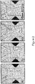
- FIG. 4 shows a sequence of micrographs where a droplet containing a fluorescent bead is selected and merged with the lateral stream. The bead can be seen both inside the droplet before fusion ( figures 4a, b ) and within the stream after fusion ( figure 4c ).
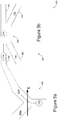
- FIGS 5a and 5b illustrate microfluidic screening apparatus 500 comprising a first, selection stage 502, and a second, droplet merger stage 504.
- a droplet 114 is selectively directed into one of a plurality of microchannels 502a, b, for example by detecting fluorescence and applying an electric field.
- the skilled person will, however, be aware of many other techniques which may be employed in this stage. Although only two streams are illustrated a large library of items for analysis may be divided into many different streams, either at a single junction or using a tree structure.
- microchannel 502b These stream of selected droplets, in the illustrated example contained within microchannel 502b are then all merged with an aqueous stream 118, in the illustrated example using a geometric technique in which the microchannel 502b is narrowed to confine a droplet 114 in at least one dimension until the droplet is allowed to expand into a chamber 506 where surface forces bring the droplet towards a more symmetrical (spherical) shape thus de-stabilising interface 120 and causing a droplet 114 to merge with the laminar flow of aqueous stream 118.
- figure 5b illustrates one example of a geometry which will cause droplet 114 to merge with stream 118, but the skilled person will appreciate that other geometries are possible.
- micro fluidic analytical devices will not work satisfactorily with a stream of emulsion as oil affects the operation of such devices.
- the above described techniques enable the contents of a droplet to be separated from the oil so efficiently that the resulting stream of aqueous solution is as if the materials carried by the solution have never been in an emulsion in the first place.
- the aqueous stream may be employed to functionally process the contents of a droplet, for example by cleaving a material such as DNA from a solid support such as a microsphere.
- microspheres or microbeads these may be used to carrier a biological material such as DNA, which may afterwards be cleaved off the solid support in or downstream of the second stream for further processing and/or analysis.
Landscapes
- Chemical & Material Sciences (AREA)
- Chemical Kinetics & Catalysis (AREA)
- Dispersion Chemistry (AREA)
- Health & Medical Sciences (AREA)
- Organic Chemistry (AREA)
- Analytical Chemistry (AREA)
- General Health & Medical Sciences (AREA)
- Hematology (AREA)
- Clinical Laboratory Science (AREA)
- Automatic Analysis And Handling Materials Therefor (AREA)
- Investigating, Analyzing Materials By Fluorescence Or Luminescence (AREA)
- Colloid Chemistry (AREA)
Claims (8)
- Verfahren zum Zugreifen auf die Inhalte eines Tröpfchens (114) einer Emulsion (116) in einem mikrofluidischen System, wobei das Verfahren umfasst:Fließenlassen der Emulsion (116) entlang eines kontinuierlichen, nichtemulgierenden Stroms eines zweiten Fluids (118), so dass das Tröpfchen (114) mit dem Strom des zweiten Fluids (118) zusammenläuft, wobei die Inhalte extrahiert und in den Strom (118) eingebracht werden,wobei das Fließenlassen eine Grenzfläche (120) zwischen der Emulsion (116) und dem Strom des zweiten Fluids (118) bereitstellt, undwobei das Extrahieren ein Anlegen eines elektrischen Feldes über die Grenzfläche (120), um eine Trajektorie des Tröpfchens (114) der Emulsion (116) zu ändern, um das Tröpfchen (114) zu veranlassen, mit dem Strom des zweiten Fluids (118) zusammenzulaufen, umfasst, undwobei das Anlegen eines elektrischen Feldes unter Verwendung eines Paars von Elektroden (112a, 112b), die seitlich auf beiden Seiten des Stroms der Emulsion und des Stroms des zweiten Fluids angeordnet sind, durchgeführt wird; undZugreifen auf die Inhalte des Tröpfchens (114) in dem zweiten Strom (118).
- Verfahren nach Anspruch 1, ferner umfassend ein Destabilisieren der Grenzfläche (120).
- Verfahren nach Anspruch 1 oder 2, wobei das elektrische Feld ein gepulstes elektrisches Feld, das durch das Paar von Elektroden (112a, 112b) angelegt wird, umfasst, und wobei, während einer Dauer eines Pulses des Felds, nur ein einziges Tröpfchen (114) zwischen den Elektroden (112a, 112b) vorhanden ist.
- Verfahren nach Anspruch 3, ferner umfassend ein Detektieren einer oder mehrerer Eigenschaften des Tröpfchens (114) und ein selektives Anlegen des Feldes als Reaktion auf das Detektieren, um die Inhalte des Tröpfchens (114) in Abhängigkeit der einen oder der mehreren Eigenschaften des Tröpfchens (114) bedingt auf den zweiten Strom (118) zu übertragen,
vorzugsweise wobei die Inhalte ein fluoreszierendes Material einschließen, wobei die eine oder die mehreren Eigenschaften Fluoreszenz einschließen, und wobei das Detektieren ein Detektieren der Fluoreszenz umfasst. - Verfahren nach einem der Ansprüche 3 oder 4, wobei der Strom des zweiten Fluids (118) einen wässrigen Strom umfasst, und
vorzugsweise wobei die fließende Emulsion (116) und der Strom des zweiten Fluids (118) im Wesentlichen parallele laminare Flüsse umfassen und wobei das elektrische Feld im Wesentlichen senkrecht zu den laminaren Flüssen ist und, optional, wobei, wenn das elektrische Feld nicht angelegt wird, das Tröpfchen (114) an der Grenzfläche in einem Abstand von größer als 1 µm von der Grenzfläche vorbei fließt, und das elektrische Feld, wenn es angelegt wird, einen Wert an der Grenzfläche von wenigstens 106 V/m aufweist. - Verfahren nach einem der vorhergehenden Ansprüche, das auf einer mikrofluidischen Plattform durchgeführt wird, wobei das zweite Fluid (118) ein wässriges Fluid umfasst, und wobei das Verfahren ferner ein Analysieren der Inhalte des Tröpfchens (114) in dem zweiten Strom (118) auf der mikrofluidischen Plattform umfasst.
- Verfahren nach einem der vorhergehenden Ansprüche, ferner umfassend ein Bilden der Emulsion (116) unter Verwendung einer mikrofluidischen Technik, und/oder
ferner umfassend ein Verwenden einer Verbindung des zweiten Fluids (118), um eine biologische oder chemische Operation an den Inhalten eines besagten Tröpfchens (114) durchzuführen. - Verfahren nach einem der vorhergehenden Ansprüche, wobei die Inhalte mindestens ein unlösliches Objekt einschließen,
vorzugsweise wobei, im Durchschnitt, die Inhalte der Tröpfchen (114) im Wesentlichen nicht mehr als ein besagtes unlösliches Objekt einschließen.
Applications Claiming Priority (2)
| Application Number | Priority Date | Filing Date | Title |
|---|---|---|---|
| GBGB0720202.1A GB0720202D0 (en) | 2007-10-16 | 2007-10-16 | Microfluidic systems |
| PCT/GB2008/050944 WO2009050512A2 (en) | 2007-10-16 | 2008-10-16 | Microfluidic systems |
Publications (2)
| Publication Number | Publication Date |
|---|---|
| EP2200740A2 EP2200740A2 (de) | 2010-06-30 |
| EP2200740B1 true EP2200740B1 (de) | 2021-02-17 |
Family
ID=38813898
Family Applications (1)
| Application Number | Title | Priority Date | Filing Date |
|---|---|---|---|
| EP08806758.2A Active EP2200740B1 (de) | 2007-10-16 | 2008-10-16 | Mikrofluidische verfahren |
Country Status (4)
| Country | Link |
|---|---|
| US (1) | US8828210B2 (de) |
| EP (1) | EP2200740B1 (de) |
| GB (1) | GB0720202D0 (de) |
| WO (1) | WO2009050512A2 (de) |
Cited By (1)
| Publication number | Priority date | Publication date | Assignee | Title |
|---|---|---|---|---|
| CN110935198A (zh) * | 2019-12-20 | 2020-03-31 | 四川大学 | 一种旋转式微通道破乳方法 |
Families Citing this family (33)
| Publication number | Priority date | Publication date | Assignee | Title |
|---|---|---|---|---|
| GB0720202D0 (en) | 2007-10-16 | 2007-11-28 | Cambridge Entpr Ltd | Microfluidic systems |
| US9267918B2 (en) | 2007-10-16 | 2016-02-23 | Cambridge Enterprise Limited | Microfluidic systems |
| WO2009149257A1 (en) | 2008-06-04 | 2009-12-10 | The University Of Chicago | The chemistrode: a plug-based microfluidic device and method for stimulation and sampling with high temporal, spatial, and chemical resolution |
| CN102483424B (zh) | 2009-06-26 | 2014-11-05 | 哈佛学院院长等 | 用于流体操作的方法以及微流体装置 |
| GB2482911A (en) | 2010-08-20 | 2012-02-22 | Sphere Fluidics Ltd | Microdroplet emulsion system |
| EP2691676B1 (de) * | 2011-03-30 | 2019-03-27 | Bio-Rad Laboratories, Inc. | Injektion mehrerer volumen in oder aus tröpfchen |
| US9203291B2 (en) | 2011-12-03 | 2015-12-01 | Thomas Krupenkin | Method and apparatus for mechanical energy harvesting using combined magnetic and microfluidic energy generation |
| WO2013096137A1 (en) * | 2011-12-20 | 2013-06-27 | Becton, Dickinson And Company | System and method to improve yield of sorted particles |
| US9312792B2 (en) | 2012-04-11 | 2016-04-12 | Thomas Nikita Krupenkin | Apparatus for closed-loop mechanical energy harvesting |
| AU2013302867A1 (en) | 2012-08-13 | 2015-02-26 | The Regents Of The University Of California | Methods and systems for detecting biological components |
| US9109583B2 (en) | 2012-08-17 | 2015-08-18 | Thomas Nikita Krupenkin | Apparatus for footwear-embedded mechanical energy harvesting using modular elements |
| US9259047B2 (en) | 2012-09-13 | 2016-02-16 | Thomas Nikita Krupenkin | Apparatus for footwear-embedded mechanical energy harvesting system based on dual-loop channel |
| US9779189B2 (en) | 2013-07-17 | 2017-10-03 | Texas Tech University System | System and method for simulation and design of discrete droplet microfluidic systems |
| GB2516684A (en) | 2013-07-30 | 2015-02-04 | Sphere Fluidics Ltd | Microfluidic devices and systems |
| GB201313583D0 (en) | 2013-07-30 | 2013-09-11 | Sphere Fluidics Ltd | Emulsion |
| EP3039119A4 (de) | 2013-08-27 | 2017-04-05 | GnuBIO, Inc. | Mikrofluidische vorrichtungen und verfahren zu deren verwendung |
| WO2015048798A1 (en) | 2013-09-30 | 2015-04-02 | Gnubio, Inc. | Microfluidic cartridge device and methods of use and assembly |
| US10697007B2 (en) | 2014-06-27 | 2020-06-30 | The Regents Of The University Of California | PCR-activated sorting (PAS) |
| US10434507B2 (en) | 2014-10-22 | 2019-10-08 | The Regents Of The University Of California | High definition microdroplet printer |
| EP3253479B1 (de) | 2015-02-04 | 2022-09-21 | The Regents of The University of California | Sequenzierung von nukleinsäuren durch barcodierung bei diskreten einheiten |
| US10213782B2 (en) * | 2015-03-03 | 2019-02-26 | The Board Of Trustees Of The University Of Illinois | Microfluidic devices |
| GB201509640D0 (en) | 2015-06-03 | 2015-07-15 | Sphere Fluidics Ltd | Systems and methods |
| GB201516447D0 (en) * | 2015-09-16 | 2015-10-28 | Sphere Fluidics Ltd | Microfluidic structure |
| EP3497228A4 (de) | 2016-08-10 | 2020-05-27 | The Regents of The University of California | Kombinierte multiple-displacement-amplifikation und pcr in einem emulsionsmikrotropfen |
| CA3047328A1 (en) | 2016-12-21 | 2018-06-28 | The Regents Of The University Of California | Single cell genomic sequencing using hydrogel based droplets |
| JP2020519305A (ja) * | 2017-04-05 | 2020-07-02 | インディアン インスティテュート オブ テクノロジー マドラス (アイアイティー マドラス)Indian Institute Of Technology Madras (Iit Madras) | 標的細胞の検出と単離のためのMicroFACS |
| US20210146365A1 (en) * | 2017-07-24 | 2021-05-20 | New York Genome Center, Inc. | Techniques for high-throughput fluid exchange in droplets |
| US10501739B2 (en) | 2017-10-18 | 2019-12-10 | Mission Bio, Inc. | Method, systems and apparatus for single cell analysis |
| US11253859B2 (en) * | 2019-04-30 | 2022-02-22 | Agilent Technologies, Inc. | Microfluidic dielectrophoretic droplet extraction |
| AU2020280104A1 (en) | 2019-05-22 | 2022-01-20 | Mission Bio, Inc. | Method and apparatus for simultaneous targeted sequencing of DNA, RNA and protein |
| US11667954B2 (en) | 2019-07-01 | 2023-06-06 | Mission Bio, Inc. | Method and apparatus to normalize quantitative readouts in single-cell experiments |
| GB202006525D0 (en) | 2020-05-04 | 2020-06-17 | Sphere Fluidics Ltd | Surfactant |
| GB2636109A (en) | 2023-11-29 | 2025-06-11 | Sphere Fluidics Ltd | Dendronized surfactants |
Family Cites Families (23)
| Publication number | Priority date | Publication date | Assignee | Title |
|---|---|---|---|---|
| BE793185A (fr) | 1971-12-23 | 1973-04-16 | Atomic Energy Commission | Appareil pour analyser et trier rapidement des particules telles que des cellules biologiques |
| ATE235292T1 (de) | 1994-10-22 | 2003-04-15 | Central Research Lab Ltd | Verfahren und vorichtung fur diffusionsaustausch zwischen nicht mischbare flüssigkeiten |
| DE19634873A1 (de) | 1996-08-29 | 1998-03-12 | Boehringer Mannheim Gmbh | System zur Unterscheidung fluoreszierender Molekülgruppen durch zeitaufgelöste Fluoreszenzmessung |
| AU4423399A (en) | 1998-06-09 | 1999-12-30 | Caliper Technologies Corporation | Fluorescent polarization detection in microfluidic systems |
| US20010048637A1 (en) | 2000-05-24 | 2001-12-06 | Weigl Bernhard H. | Microfluidic system and method |
| WO2002023163A1 (en) | 2000-09-15 | 2002-03-21 | California Institute Of Technology | Microfabricated crossflow devices and methods |
| EP1343973B2 (de) | 2000-11-16 | 2020-09-16 | California Institute Of Technology | Vorrichtung und verfahren zur durchführung von assays und screening mit hohem durchsatz |
| JP4019044B2 (ja) | 2001-07-10 | 2007-12-05 | 財団法人神奈川科学技術アカデミー | 多層流マイクロチャンネルの集積化構造体とこれを用いる多層流操作方法 |
| US6838056B2 (en) | 2002-07-08 | 2005-01-04 | Innovative Micro Technology | Method and apparatus for sorting biological cells with a MEMS device |
| EP1380337B1 (de) | 2002-07-12 | 2012-11-14 | Tosoh Corporation | Vorrichtung mit feinen Kanälen und chemisches Verfahren zur Verwendung dieser Vorrichtung für Fluide |
| US7547380B2 (en) | 2003-01-13 | 2009-06-16 | North Carolina State University | Droplet transportation devices and methods having a fluid surface |
| US7595195B2 (en) | 2003-02-11 | 2009-09-29 | The Regents Of The University Of California | Microfluidic devices for controlled viscous shearing and formation of amphiphilic vesicles |
| TW577855B (en) | 2003-05-21 | 2004-03-01 | Univ Nat Cheng Kung | Chip-type micro-fluid particle 3-D focusing and detection device |
| US7298478B2 (en) | 2003-08-14 | 2007-11-20 | Cytonome, Inc. | Optical detector for a particle sorting system |
| WO2005021151A1 (en) | 2003-08-27 | 2005-03-10 | President And Fellows Of Harvard College | Electronic control of fluidic species |
| US20060280029A1 (en) | 2005-06-13 | 2006-12-14 | President And Fellows Of Harvard College | Microfluidic mixer |
| WO2007081385A2 (en) | 2006-01-11 | 2007-07-19 | Raindance Technologies, Inc. | Microfluidic devices and methods of use in the formation and control of nanoreactors |
| EP2530167A1 (de) | 2006-05-11 | 2012-12-05 | Raindance Technologies, Inc. | Mikrofluidische Vorrichtungen |
| US8691164B2 (en) | 2007-04-20 | 2014-04-08 | Celula, Inc. | Cell sorting system and methods |
| GB0720202D0 (en) | 2007-10-16 | 2007-11-28 | Cambridge Entpr Ltd | Microfluidic systems |
| CN102472702B (zh) | 2009-07-07 | 2014-05-21 | 索尼公司 | 一种检测样品中的颗粒的方法 |
| DE102010012580A1 (de) | 2010-03-23 | 2011-09-29 | Hochschule Niederrhein | Vorrichtung und Verfahren zur zeitaufgelösten Durchflusszytometrie |
| BR112012025925B1 (pt) | 2010-04-13 | 2020-03-17 | Univation Technologies, Llc | Mistura polimérica e filme |
-
2007
- 2007-10-16 GB GBGB0720202.1A patent/GB0720202D0/en not_active Ceased
-
2008
- 2008-10-16 WO PCT/GB2008/050944 patent/WO2009050512A2/en not_active Ceased
- 2008-10-16 EP EP08806758.2A patent/EP2200740B1/de active Active
- 2008-10-16 US US12/738,268 patent/US8828210B2/en active Active
Non-Patent Citations (1)
| Title |
|---|
| None * |
Cited By (2)
| Publication number | Priority date | Publication date | Assignee | Title |
|---|---|---|---|---|
| CN110935198A (zh) * | 2019-12-20 | 2020-03-31 | 四川大学 | 一种旋转式微通道破乳方法 |
| CN110935198B (zh) * | 2019-12-20 | 2023-05-26 | 四川大学 | 一种旋转式微通道破乳方法 |
Also Published As
| Publication number | Publication date |
|---|---|
| EP2200740A2 (de) | 2010-06-30 |
| GB0720202D0 (en) | 2007-11-28 |
| US20120091004A1 (en) | 2012-04-19 |
| WO2009050512A2 (en) | 2009-04-23 |
| US8828210B2 (en) | 2014-09-09 |
| WO2009050512A3 (en) | 2010-02-25 |
Similar Documents
| Publication | Publication Date | Title |
|---|---|---|
| EP2200740B1 (de) | Mikrofluidische verfahren | |
| US9267918B2 (en) | Microfluidic systems | |
| Fidalgo et al. | From microdroplets to microfluidics: selective emulsion separation in microfluidic devices | |
| EP2324352B1 (de) | Verfahren und vorrichtung zur diskretisierung und manipulation von probenvolumen | |
| US7179423B2 (en) | Microfluidic system including a virtual wall fluid interface port for interfacing fluids with the microfluidic system | |
| Sesen et al. | Droplet control technologies for microfluidic high throughput screening (μHTS) | |
| Mazutis et al. | A fast and efficient microfluidic system for highly selective one-to-one droplet fusion | |
| US20030015425A1 (en) | Microfluidic system including a virtual wall fluid interface port for interfacing fluids with the microfluidic system | |
| Leman et al. | Droplet-based microfluidics at the femtolitre scale | |
| US9446360B2 (en) | Microfluidic system and methods for highly selective droplet fusion | |
| Pompano et al. | Microfluidics using spatially defined arrays of droplets in one, two, and three dimensions | |
| CA2636855C (en) | Microfluidic devices and methods of use in the formation and control of nanoreactors | |
| JP5893620B2 (ja) | 合成液体セル | |
| JP2005514187A (ja) | 流体をマイクロ流体システムと相互接続するための仮想壁流体相互接続ポートを含むマイクロ流体システム | |
| US8597486B2 (en) | Droplet based miniaturized device with on-demand droplet-trapping, -fusion, and -releasing | |
| Simon et al. | Microfluidic droplet manipulations and their applications | |
| Rane et al. | Counting single molecules in sub-nanolitre droplets | |
| US20120006681A1 (en) | Controlled Dispensing of Ultrafine, Variable Volume, Emulsion Droplets | |
| Stanley et al. | Continuous and segmented flow microfluidics: Applications in high-throughput chemistry and biology | |
| CN110918141B (zh) | 微流控芯片及含有该微流控芯片的装置,以及用于制备微乳化液滴的应用 | |
| Srisa-Art et al. | High-throughput confinement and detection of single DNA molecules in aqueous microdroplets | |
| Zeng et al. | Basic technologies for droplet microfluidics | |
| Zagnoni et al. | Droplet microfluidics for high-throughput analysis of cells and particles | |
| Tkaczyk et al. | Microfluidic droplet consistency monitoring and encapsulated cell detection via laser excitation | |
| Jung et al. | Interfacial tension controlled fusion of individual femtolitre droplets and triggering of confined chemical reactions on demand |
Legal Events
| Date | Code | Title | Description |
|---|---|---|---|
| PUAI | Public reference made under article 153(3) epc to a published international application that has entered the european phase |
Free format text: ORIGINAL CODE: 0009012 |
|
| 17P | Request for examination filed |
Effective date: 20100423 |
|
| AK | Designated contracting states |
Kind code of ref document: A2 Designated state(s): AT BE BG CH CY CZ DE DK EE ES FI FR GB GR HR HU IE IS IT LI LT LU LV MC MT NL NO PL PT RO SE SI SK TR |
|
| AX | Request for extension of the european patent |
Extension state: AL BA MK RS |
|
| RIN1 | Information on inventor provided before grant (corrected) |
Inventor name: FIDALGO, LUIS M. Inventor name: GRAEME, WHYTE Inventor name: BRATTON, DANIEL Inventor name: HUCK, WILHELM, T., S. Inventor name: ABELL, CHRIS |
|
| DAX | Request for extension of the european patent (deleted) | ||
| STAA | Information on the status of an ep patent application or granted ep patent |
Free format text: STATUS: EXAMINATION IS IN PROGRESS |
|
| 17Q | First examination report despatched |
Effective date: 20171205 |
|
| GRAP | Despatch of communication of intention to grant a patent |
Free format text: ORIGINAL CODE: EPIDOSNIGR1 |
|
| STAA | Information on the status of an ep patent application or granted ep patent |
Free format text: STATUS: GRANT OF PATENT IS INTENDED |
|
| RIC1 | Information provided on ipc code assigned before grant |
Ipc: B01L 3/00 20060101ALI20200526BHEP Ipc: G01N 35/00 20060101ALI20200526BHEP Ipc: B01J 19/00 20060101AFI20200526BHEP |
|
| INTG | Intention to grant announced |
Effective date: 20200629 |
|
| GRAS | Grant fee paid |
Free format text: ORIGINAL CODE: EPIDOSNIGR3 |
|
| GRAA | (expected) grant |
Free format text: ORIGINAL CODE: 0009210 |
|
| STAA | Information on the status of an ep patent application or granted ep patent |
Free format text: STATUS: THE PATENT HAS BEEN GRANTED |
|
| AK | Designated contracting states |
Kind code of ref document: B1 Designated state(s): AT BE BG CH CY CZ DE DK EE ES FI FR GB GR HR HU IE IS IT LI LT LU LV MC MT NL NO PL PT RO SE SI SK TR |
|
| REG | Reference to a national code |
Ref country code: GB Ref legal event code: FG4D |
|
| REG | Reference to a national code |
Ref country code: CH Ref legal event code: EP |
|
| REG | Reference to a national code |
Ref country code: DE Ref legal event code: R096 Ref document number: 602008063708 Country of ref document: DE |
|
| REG | Reference to a national code |
Ref country code: AT Ref legal event code: REF Ref document number: 1360746 Country of ref document: AT Kind code of ref document: T Effective date: 20210315 |
|
| REG | Reference to a national code |
Ref country code: IE Ref legal event code: FG4D |
|
| REG | Reference to a national code |
Ref country code: CH Ref legal event code: NV Representative=s name: SERVOPATENT GMBH, CH |
|
| REG | Reference to a national code |
Ref country code: LT Ref legal event code: MG9D |
|
| REG | Reference to a national code |
Ref country code: NL Ref legal event code: MP Effective date: 20210217 |
|
| PG25 | Lapsed in a contracting state [announced via postgrant information from national office to epo] |
Ref country code: HR Free format text: LAPSE BECAUSE OF FAILURE TO SUBMIT A TRANSLATION OF THE DESCRIPTION OR TO PAY THE FEE WITHIN THE PRESCRIBED TIME-LIMIT Effective date: 20210217 Ref country code: GR Free format text: LAPSE BECAUSE OF FAILURE TO SUBMIT A TRANSLATION OF THE DESCRIPTION OR TO PAY THE FEE WITHIN THE PRESCRIBED TIME-LIMIT Effective date: 20210518 Ref country code: FI Free format text: LAPSE BECAUSE OF FAILURE TO SUBMIT A TRANSLATION OF THE DESCRIPTION OR TO PAY THE FEE WITHIN THE PRESCRIBED TIME-LIMIT Effective date: 20210217 Ref country code: LT Free format text: LAPSE BECAUSE OF FAILURE TO SUBMIT A TRANSLATION OF THE DESCRIPTION OR TO PAY THE FEE WITHIN THE PRESCRIBED TIME-LIMIT Effective date: 20210217 Ref country code: BG Free format text: LAPSE BECAUSE OF FAILURE TO SUBMIT A TRANSLATION OF THE DESCRIPTION OR TO PAY THE FEE WITHIN THE PRESCRIBED TIME-LIMIT Effective date: 20210517 Ref country code: NO Free format text: LAPSE BECAUSE OF FAILURE TO SUBMIT A TRANSLATION OF THE DESCRIPTION OR TO PAY THE FEE WITHIN THE PRESCRIBED TIME-LIMIT Effective date: 20210517 Ref country code: PT Free format text: LAPSE BECAUSE OF FAILURE TO SUBMIT A TRANSLATION OF THE DESCRIPTION OR TO PAY THE FEE WITHIN THE PRESCRIBED TIME-LIMIT Effective date: 20210617 |
|
| REG | Reference to a national code |
Ref country code: AT Ref legal event code: MK05 Ref document number: 1360746 Country of ref document: AT Kind code of ref document: T Effective date: 20210217 |
|
| PG25 | Lapsed in a contracting state [announced via postgrant information from national office to epo] |
Ref country code: PL Free format text: LAPSE BECAUSE OF FAILURE TO SUBMIT A TRANSLATION OF THE DESCRIPTION OR TO PAY THE FEE WITHIN THE PRESCRIBED TIME-LIMIT Effective date: 20210217 Ref country code: NL Free format text: LAPSE BECAUSE OF FAILURE TO SUBMIT A TRANSLATION OF THE DESCRIPTION OR TO PAY THE FEE WITHIN THE PRESCRIBED TIME-LIMIT Effective date: 20210217 Ref country code: LV Free format text: LAPSE BECAUSE OF FAILURE TO SUBMIT A TRANSLATION OF THE DESCRIPTION OR TO PAY THE FEE WITHIN THE PRESCRIBED TIME-LIMIT Effective date: 20210217 Ref country code: SE Free format text: LAPSE BECAUSE OF FAILURE TO SUBMIT A TRANSLATION OF THE DESCRIPTION OR TO PAY THE FEE WITHIN THE PRESCRIBED TIME-LIMIT Effective date: 20210217 |
|
| PG25 | Lapsed in a contracting state [announced via postgrant information from national office to epo] |
Ref country code: IS Free format text: LAPSE BECAUSE OF FAILURE TO SUBMIT A TRANSLATION OF THE DESCRIPTION OR TO PAY THE FEE WITHIN THE PRESCRIBED TIME-LIMIT Effective date: 20210617 |
|
| PG25 | Lapsed in a contracting state [announced via postgrant information from national office to epo] |
Ref country code: CZ Free format text: LAPSE BECAUSE OF FAILURE TO SUBMIT A TRANSLATION OF THE DESCRIPTION OR TO PAY THE FEE WITHIN THE PRESCRIBED TIME-LIMIT Effective date: 20210217 Ref country code: EE Free format text: LAPSE BECAUSE OF FAILURE TO SUBMIT A TRANSLATION OF THE DESCRIPTION OR TO PAY THE FEE WITHIN THE PRESCRIBED TIME-LIMIT Effective date: 20210217 Ref country code: AT Free format text: LAPSE BECAUSE OF FAILURE TO SUBMIT A TRANSLATION OF THE DESCRIPTION OR TO PAY THE FEE WITHIN THE PRESCRIBED TIME-LIMIT Effective date: 20210217 |
|
| REG | Reference to a national code |
Ref country code: DE Ref legal event code: R097 Ref document number: 602008063708 Country of ref document: DE |
|
| PG25 | Lapsed in a contracting state [announced via postgrant information from national office to epo] |
Ref country code: SK Free format text: LAPSE BECAUSE OF FAILURE TO SUBMIT A TRANSLATION OF THE DESCRIPTION OR TO PAY THE FEE WITHIN THE PRESCRIBED TIME-LIMIT Effective date: 20210217 Ref country code: DK Free format text: LAPSE BECAUSE OF FAILURE TO SUBMIT A TRANSLATION OF THE DESCRIPTION OR TO PAY THE FEE WITHIN THE PRESCRIBED TIME-LIMIT Effective date: 20210217 Ref country code: ES Free format text: LAPSE BECAUSE OF FAILURE TO SUBMIT A TRANSLATION OF THE DESCRIPTION OR TO PAY THE FEE WITHIN THE PRESCRIBED TIME-LIMIT Effective date: 20210217 Ref country code: RO Free format text: LAPSE BECAUSE OF FAILURE TO SUBMIT A TRANSLATION OF THE DESCRIPTION OR TO PAY THE FEE WITHIN THE PRESCRIBED TIME-LIMIT Effective date: 20210217 |
|
| PLBE | No opposition filed within time limit |
Free format text: ORIGINAL CODE: 0009261 |
|
| STAA | Information on the status of an ep patent application or granted ep patent |
Free format text: STATUS: NO OPPOSITION FILED WITHIN TIME LIMIT |
|
| 26N | No opposition filed |
Effective date: 20211118 |
|
| PG25 | Lapsed in a contracting state [announced via postgrant information from national office to epo] |
Ref country code: SI Free format text: LAPSE BECAUSE OF FAILURE TO SUBMIT A TRANSLATION OF THE DESCRIPTION OR TO PAY THE FEE WITHIN THE PRESCRIBED TIME-LIMIT Effective date: 20210217 |
|
| PG25 | Lapsed in a contracting state [announced via postgrant information from national office to epo] |
Ref country code: IT Free format text: LAPSE BECAUSE OF FAILURE TO SUBMIT A TRANSLATION OF THE DESCRIPTION OR TO PAY THE FEE WITHIN THE PRESCRIBED TIME-LIMIT Effective date: 20210217 |
|
| PG25 | Lapsed in a contracting state [announced via postgrant information from national office to epo] |
Ref country code: IS Free format text: LAPSE BECAUSE OF FAILURE TO SUBMIT A TRANSLATION OF THE DESCRIPTION OR TO PAY THE FEE WITHIN THE PRESCRIBED TIME-LIMIT Effective date: 20210617 |
|
| REG | Reference to a national code |
Ref country code: BE Ref legal event code: MM Effective date: 20211031 |
|
| PG25 | Lapsed in a contracting state [announced via postgrant information from national office to epo] |
Ref country code: MC Free format text: LAPSE BECAUSE OF FAILURE TO SUBMIT A TRANSLATION OF THE DESCRIPTION OR TO PAY THE FEE WITHIN THE PRESCRIBED TIME-LIMIT Effective date: 20210217 |
|
| PG25 | Lapsed in a contracting state [announced via postgrant information from national office to epo] |
Ref country code: LU Free format text: LAPSE BECAUSE OF NON-PAYMENT OF DUE FEES Effective date: 20211016 Ref country code: BE Free format text: LAPSE BECAUSE OF NON-PAYMENT OF DUE FEES Effective date: 20211031 |
|
| PG25 | Lapsed in a contracting state [announced via postgrant information from national office to epo] |
Ref country code: IE Free format text: LAPSE BECAUSE OF NON-PAYMENT OF DUE FEES Effective date: 20211016 |
|
| PG25 | Lapsed in a contracting state [announced via postgrant information from national office to epo] |
Ref country code: HU Free format text: LAPSE BECAUSE OF FAILURE TO SUBMIT A TRANSLATION OF THE DESCRIPTION OR TO PAY THE FEE WITHIN THE PRESCRIBED TIME-LIMIT; INVALID AB INITIO Effective date: 20081016 Ref country code: CY Free format text: LAPSE BECAUSE OF FAILURE TO SUBMIT A TRANSLATION OF THE DESCRIPTION OR TO PAY THE FEE WITHIN THE PRESCRIBED TIME-LIMIT Effective date: 20210217 |
|
| P01 | Opt-out of the competence of the unified patent court (upc) registered |
Effective date: 20230526 |
|
| PG25 | Lapsed in a contracting state [announced via postgrant information from national office to epo] |
Ref country code: TR Free format text: LAPSE BECAUSE OF FAILURE TO SUBMIT A TRANSLATION OF THE DESCRIPTION OR TO PAY THE FEE WITHIN THE PRESCRIBED TIME-LIMIT Effective date: 20210217 |
|
| PG25 | Lapsed in a contracting state [announced via postgrant information from national office to epo] |
Ref country code: MT Free format text: LAPSE BECAUSE OF FAILURE TO SUBMIT A TRANSLATION OF THE DESCRIPTION OR TO PAY THE FEE WITHIN THE PRESCRIBED TIME-LIMIT Effective date: 20210217 |
|
| PGFP | Annual fee paid to national office [announced via postgrant information from national office to epo] |
Ref country code: GB Payment date: 20240829 Year of fee payment: 17 |
|
| PGFP | Annual fee paid to national office [announced via postgrant information from national office to epo] |
Ref country code: FR Payment date: 20240909 Year of fee payment: 17 |
|
| PGFP | Annual fee paid to national office [announced via postgrant information from national office to epo] |
Ref country code: DE Payment date: 20240904 Year of fee payment: 17 |
|
| PGFP | Annual fee paid to national office [announced via postgrant information from national office to epo] |
Ref country code: CH Payment date: 20241101 Year of fee payment: 17 |