EP2200338A2 - Vorrichtung und Verfahren zur Erzeugung von direktionalem Ton - Google Patents
Vorrichtung und Verfahren zur Erzeugung von direktionalem Ton Download PDFInfo
- Publication number
- EP2200338A2 EP2200338A2 EP09178723A EP09178723A EP2200338A2 EP 2200338 A2 EP2200338 A2 EP 2200338A2 EP 09178723 A EP09178723 A EP 09178723A EP 09178723 A EP09178723 A EP 09178723A EP 2200338 A2 EP2200338 A2 EP 2200338A2
- Authority
- EP
- European Patent Office
- Prior art keywords
- sound
- loudspeakers
- edge
- loudspeaker array
- internal loudspeaker
- Prior art date
- Legal status (The legal status is an assumption and is not a legal conclusion. Google has not performed a legal analysis and makes no representation as to the accuracy of the status listed.)
- Withdrawn
Links
Images


Classifications
-
- H—ELECTRICITY
- H04—ELECTRIC COMMUNICATION TECHNIQUE
- H04R—LOUDSPEAKERS, MICROPHONES, GRAMOPHONE PICK-UPS OR LIKE ACOUSTIC ELECTROMECHANICAL TRANSDUCERS; ELECTRIC HEARING AIDS; PUBLIC ADDRESS SYSTEMS
- H04R1/00—Details of transducers, loudspeakers or microphones
- H04R1/20—Arrangements for obtaining desired frequency or directional characteristics
- H04R1/32—Arrangements for obtaining desired frequency or directional characteristics for obtaining desired directional characteristic only
- H04R1/40—Arrangements for obtaining desired frequency or directional characteristics for obtaining desired directional characteristic only by combining a number of identical transducers
-
- H—ELECTRICITY
- H04—ELECTRIC COMMUNICATION TECHNIQUE
- H04R—LOUDSPEAKERS, MICROPHONES, GRAMOPHONE PICK-UPS OR LIKE ACOUSTIC ELECTROMECHANICAL TRANSDUCERS; ELECTRIC HEARING AIDS; PUBLIC ADDRESS SYSTEMS
- H04R3/00—Circuits for transducers
- H04R3/12—Circuits for transducers for distributing signals to two or more loudspeakers
-
- H—ELECTRICITY
- H04—ELECTRIC COMMUNICATION TECHNIQUE
- H04R—LOUDSPEAKERS, MICROPHONES, GRAMOPHONE PICK-UPS OR LIKE ACOUSTIC ELECTROMECHANICAL TRANSDUCERS; ELECTRIC HEARING AIDS; PUBLIC ADDRESS SYSTEMS
- H04R1/00—Details of transducers, loudspeakers or microphones
- H04R1/20—Arrangements for obtaining desired frequency or directional characteristics
- H04R1/32—Arrangements for obtaining desired frequency or directional characteristics for obtaining desired directional characteristic only
- H04R1/34—Arrangements for obtaining desired frequency or directional characteristics for obtaining desired directional characteristic only by using a single transducer with sound reflecting, diffracting, directing or guiding means
- H04R1/345—Arrangements for obtaining desired frequency or directional characteristics for obtaining desired directional characteristic only by using a single transducer with sound reflecting, diffracting, directing or guiding means for loudspeakers
-
- H—ELECTRICITY
- H04—ELECTRIC COMMUNICATION TECHNIQUE
- H04R—LOUDSPEAKERS, MICROPHONES, GRAMOPHONE PICK-UPS OR LIKE ACOUSTIC ELECTROMECHANICAL TRANSDUCERS; ELECTRIC HEARING AIDS; PUBLIC ADDRESS SYSTEMS
- H04R1/00—Details of transducers, loudspeakers or microphones
- H04R1/20—Arrangements for obtaining desired frequency or directional characteristics
- H04R1/32—Arrangements for obtaining desired frequency or directional characteristics for obtaining desired directional characteristic only
- H04R1/40—Arrangements for obtaining desired frequency or directional characteristics for obtaining desired directional characteristic only by combining a number of identical transducers
- H04R1/403—Arrangements for obtaining desired frequency or directional characteristics for obtaining desired directional characteristic only by combining a number of identical transducers loud-speakers
-
- H—ELECTRICITY
- H04—ELECTRIC COMMUNICATION TECHNIQUE
- H04R—LOUDSPEAKERS, MICROPHONES, GRAMOPHONE PICK-UPS OR LIKE ACOUSTIC ELECTROMECHANICAL TRANSDUCERS; ELECTRIC HEARING AIDS; PUBLIC ADDRESS SYSTEMS
- H04R2201/00—Details of transducers, loudspeakers or microphones covered by H04R1/00 but not provided for in any of its subgroups
- H04R2201/40—Details of arrangements for obtaining desired directional characteristic by combining a number of identical transducers covered by H04R1/40 but not provided for in any of its subgroups
- H04R2201/403—Linear arrays of transducers
-
- H—ELECTRICITY
- H04—ELECTRIC COMMUNICATION TECHNIQUE
- H04R—LOUDSPEAKERS, MICROPHONES, GRAMOPHONE PICK-UPS OR LIKE ACOUSTIC ELECTROMECHANICAL TRANSDUCERS; ELECTRIC HEARING AIDS; PUBLIC ADDRESS SYSTEMS
- H04R2201/00—Details of transducers, loudspeakers or microphones covered by H04R1/00 but not provided for in any of its subgroups
- H04R2201/40—Details of arrangements for obtaining desired directional characteristic by combining a number of identical transducers covered by H04R1/40 but not provided for in any of its subgroups
- H04R2201/405—Non-uniform arrays of transducers or a plurality of uniform arrays with different transducer spacing
-
- H—ELECTRICITY
- H04—ELECTRIC COMMUNICATION TECHNIQUE
- H04R—LOUDSPEAKERS, MICROPHONES, GRAMOPHONE PICK-UPS OR LIKE ACOUSTIC ELECTROMECHANICAL TRANSDUCERS; ELECTRIC HEARING AIDS; PUBLIC ADDRESS SYSTEMS
- H04R2203/00—Details of circuits for transducers, loudspeakers or microphones covered by H04R3/00 but not provided for in any of its subgroups
- H04R2203/12—Beamforming aspects for stereophonic sound reproduction with loudspeaker arrays
-
- H—ELECTRICITY
- H04—ELECTRIC COMMUNICATION TECHNIQUE
- H04R—LOUDSPEAKERS, MICROPHONES, GRAMOPHONE PICK-UPS OR LIKE ACOUSTIC ELECTROMECHANICAL TRANSDUCERS; ELECTRIC HEARING AIDS; PUBLIC ADDRESS SYSTEMS
- H04R2430/00—Signal processing covered by H04R, not provided for in its groups
- H04R2430/20—Processing of the output signals of the acoustic transducers of an array for obtaining a desired directivity characteristic
- H04R2430/25—Array processing for suppression of unwanted side-lobes in directivity characteristics, e.g. a blocking matrix
Definitions
- the following description relates to sound processing technology, and more particularly, to an apparatus and method for generating directional sound to be output to a specific sound zone.
- a sound generating apparatus such as typical loudspeakers cannot output directional sound, and output sound is spread out in all directions. That is, although a sound pressure level may vary depending on a position of a listener, sound is spread out around the sound generating apparatus.
- the output sound may act as a disruption when delivered to a person who does not wish to hear it.
- headphones or earphones may enable the output sound to be delivered to a specific listener, these may limit a movement of the listener and may even impair the listener's ability to hear other sound.
- the size of the sound generating apparatus in such a method may need to increase.
- the cost of the sound generating apparatus may increase as the apparatus likely need a plurality of sound sources having good efficiency in all frequency bands.
- sound sources for a high-frequency signal may be arranged at small intervals and a separate sound source for amplifying a low-frequency signal may be arranged at both ends of the sound source.
- this may not improve directivity of the sound and merely increase the quality of sound in a low-frequency band.
- an apparatus and method for generating directional sound that improves directivity of sound by synthesizing output sound signals of an internal loudspeaker array and an edge loudspeaker cluster to remove output in side directions while maintaining directivity in a sound output direction.
- an apparatus to generate directional sound including an internal loudspeaker array and edge loudspeakers.
- the internal loudspeaker array includes at least one sound source, and the edge loudspeakers are located at respective ends of the internal loudspeaker array, each of the edge loudspeakers including a sound source having directivity.
- Each of the edge loudspeakers may include a plurality of edge loudspeakers.
- the sound source of each of the edge loudspeakers may be a high-order directivity sound source.
- the apparatus may further include a controller configured to control the internal loudspeaker array and the edge loudspeakers to remove output sound in predetermined directions, for example, side directions, while maintaining directivity of the output sound toward a specific direction by synthesizing sound signals output from the internal loudspeaker array and the edge loudspeakers.
- a controller configured to control the internal loudspeaker array and the edge loudspeakers to remove output sound in predetermined directions, for example, side directions, while maintaining directivity of the output sound toward a specific direction by synthesizing sound signals output from the internal loudspeaker array and the edge loudspeakers.
- the controller may include a filter configured to perform a high-frequency pass filtering or low-frequency pass filtering on an input sound signal, a signal processor configured to generate a multi-channel signal to deliver a high-frequency signal from the filter to the internal loudspeaker array and a low-frequency signal from the filter to the internal loudspeaker array or the edge loudspeakers, and a driver configured to receive the multi-channel signal and drive individual loudspeakers of the internal loudspeaker array and the edge loudspeakers.
- a filter configured to perform a high-frequency pass filtering or low-frequency pass filtering on an input sound signal
- a signal processor configured to generate a multi-channel signal to deliver a high-frequency signal from the filter to the internal loudspeaker array and a low-frequency signal from the filter to the internal loudspeaker array or the edge loudspeakers
- a driver configured to receive the multi-channel signal and drive individual loudspeakers of the internal loudspeaker array and the edge loudspeakers.
- Each of the edge loudspeakers may include a sound transducer to output sound waves having opposite phases forward and backward, a reflective plate located at a rear of the sound transducer, and a first blocking plate provided between a front portion and a rear portion of the sound transducer to increase an interference distance between a forward radiation sound from the sound transducer and a backward radiation sound of the sound transducer obtained where a sound wave output from the sound transducer is reflected by the reflective plate.
- Each of the edge loudspeakers may further include a second blocking plate connected to the reflective plate and provided to cover an area on top of the sound transducer and/or an area at bottom of the sound transducer, to reduce directivity of sound waves output from the sound transducer in a vertical direction.
- Each of the edge loudspeakers may further include a sound-absorbing member provided to the reflective plate and/or the first blocking plate.
- a method for generating directional sound performed by a directional sound generating apparatus, the method including generating a sound signal for a directional loudspeaker and a sound signal for a non-directional loudspeaker, and supplying the sound signal for the non-directional loudspeaker to an internal loudspeaker array of the directional sound generating apparatus, the internal loudspeaker array comprising at least one sound source, and supplying the sound signal for the directional loudspeaker to edge loudspeakers of the directional sound generating apparatus, the edge loudspeakers being located at respective ends of the internal loudspeaker array.
- the method may further include controlling the internal loudspeaker array and the edge loudspeakers to remove output sound in predetermined directions while maintaining directivity of the output sound toward a specific direction by synthesizing sound signals output from the internal loudspeaker array and the edge loudspeakers.
- the controlling of the internal loudspeaker array and the edge loudspeakers may include performing a high-frequency filtering or low-frequency filtering on an input sound signal, generating a multi-channel signal to deliver a high-frequency signal to the internal loudspeaker array and a low-frequency signal to the internal loudspeaker array or the edge loudspeakers, and driving individual loudspeakers of the internal loudspeaker array and the edge loudspeakers.
- FIG. 1 illustrates sound radiation patterns of an exemplary sound source clustering.
- a pair of sound sources 110a and 110b spaced by the same distance from a center of the array may be defined as a sound source cluster.
- a distance between the two sound sources 110a and 110b is x
- Equation 1 the sharpest radiation pattern among radiation patterns of sound generated by sound source clusters, which include sound sources symmetrically spaced the same distance from the center, is generated by the sound source cluster 110a and 110b located at both ends of the sound source array.
- FIG. 2 shows a graph illustrating sound radiation patterns of the exemplary sound source clustering of FIG. 1 .
- FIG. 2 shows sound pressure curves when distances x between two sound sources in a sound source cluster are 0.1, 0.2, 0.5 and 1 times the wavelength. It can be seen that the sharpest sound pressure curve is obtained when the distance x between the two sound sources is the greatest (one times the wavelength). That is, a sound pressure curve of the sound source cluster at the edges has a sharp main lobe at a center of the graph and side lobe values appear when the angle from a front direction increases.
- FIG. 3 shows a graph illustrating sound radiation patterns where a high-order directivity sound source is used as an edge loudspeaker.
- Another exemplary sound source cluster may be configured by providing a high-order directivity sound source (transducer) at edges of a sound generating apparatus.
- the sound transducer may be designed to output sounds having opposite phases forward and backward.
- the number of pairs of the sound sources corresponds to an order, and a higher order structure is obtained where a structure to output sounds having opposite phases forward and backward is repeated.
- FIG. 3 shows a sound radiation result where transducers having second-order cosine directivity (cos 2 ⁇ ) are used in the edge loudspeaker cluster. It can be seen that a main lobe width and a side lobe value decrease, unlike the case where transducers having no directivity are used in the cluster.
- second-order directional transducers in which x corresponds to a 1/10 wavelength may provide a similar directivity compared to the use of non-directional transducers in which x corresponds to a 1/2 wavelength.
- FIG. 4 shows a graph illustrating sound radiation patterns in a case of internal loudspeakers and edge loudspeakers and in a case of synthesized sound where second-order directional transducers are used as edge loudspeakers.
- the edge loudspeaker cluster including the high-directivity transducers may be effective when an interval between the high-directivity transducers is similar to or smaller than the wavelength. This is because a main lobe and a side lobe of the sound radiation pattern generated by the edge loudspeaker cluster have opposite phases, as can be seen from Equation 2. Since a sound radiation pattern of the internal loudspeaker cluster having sound sources has the same phase at the main lobe and the side lobe, when the two patterns are coupled, the resulting pattern is enlarged at the main lobe due to the same phase and cancelled at the side lobes due to an opposite phase. That is, the side lobes are cancelled and the main lobe is amplified.
- the main lobe generated by the internal loudspeaker cluster has a narrow width and the side lobes are cancelled.
- the side lobe is smaller than that of a typical sound source where an edge loudspeaker cluster uses high-directivity transducers. Accordingly, when a sound pressure radiation pattern generated by the internal loudspeaker cluster is coupled with a sound pressure radiation pattern generated by the edge loudspeaker cluster in a cancellation fashion, contribution of the edge loudspeaker cluster increases such that a sharper sound beam is obtained. As a result, a narrower sound pressure radiation pattern can be obtained than that of an array having non-directional sound source clusters.
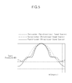
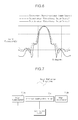
- FIG. 5 shows a graph illustrating sound radiation patterns where non-directional transducers and where high-directivity transducers are used at edges of an array, for a sound signal at a frequency of 320 Hz
- FIG. 6 shows a graph illustrating sound radiation patterns where non-directional transducers and where high-directivity transducers are used at the edges of the array, for a sound signal at a frequency of 640 Hz.
- the sound from the high-directivity transducers located at the edges may be selectively muted and only the non-directional internal transducers may be driven.
- a sharp sound beam can be implemented using the above-described effect of the high-directivity cluster, and in a high-frequency band in which a sufficiently small beam width can be implemented using a conventional technique, a narrow sound pressure radiation pattern can be obtained using only an internal loudspeaker array.
- FIG. 7 shows an exemplary apparatus to generate directional sound.
- the direction sound generating apparatus includes edge loudspeakers 710a and 710b, an internal loudspeaker array 720, and a controller 730.
- the internal loudspeaker array 720 may include at least one sound source.
- the at least one sound source of the internal loudspeaker array may include typical sound transducer(s) having low directivity and generates sound having a wide directivity pattern.
- the edge loudspeakers 710a and 710b are located at ends of the internal loudspeaker array 720, respectively, and include a sound source having directivity.
- This sound source may be a sound transducer having high directivity in a center direction and a sound attenuation property in side directions.
- Each of the edge loudspeaker units 710a and 710b may include several directional transducers or one high-order directivity transducer.
- An example of high-directivity loudspeakers used as the edge loudspeakers 710a and 710b will be described later with reference to FIGS. 9A to 9D .
- the controller 730 synthesizes output sound signals of the internal loudspeaker array 720 and the edge loudspeakers 710a and 710b, and controls the internal loudspeaker array 720 and the edge loudspeakers 710a and 710b to remove output in side directions while maintaining directivity of output sound. For example, the controller 730 performs signal processing to synthesize sounds generated by the edge loudspeakers 710a and 710b and the internal loudspeaker array 720 and remove side lobes while maintaining high directivity in a center direction.
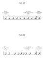
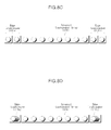
- FIGS. 8A to 8D illustrates several exemplary arrangements of sound sources in an apparatus for generating directional sound.
- a plurality of sound transducers may be arranged at the same intervals in an internal loudspeaker array 820, as shown in FIG. 8A .
- a plurality of sound transducers may be arranged at different intervals in the internal loudspeaker array 820, as shown in FIG. 8B .
- the sound transducers may be arranged at smaller intervals toward the center of the internal loudspeaker array 820 and at greater intervals towards the edge of the internal loudspeaker array 820.
- Each of the edge loudspeakers 810a and 810b may comprise two or more edge loudspeakers, as shown in FIG. 8C .
- the edge loudspeaker may comprise high-order sound transducers, as shown in FIG. 8D .
- FIGS. 9A to 9D illustrate several exemplary implementations of a high-directivity loudspeaker.
- a baffle 910 is formed as a plate in parallel with a propagation direction of a sound wave output from a sound transducer 905.
- the baffle 910 is vertically and horizontally smaller than a reflective plate 920 and separates a front portion and a rear portion of the sound transducer 905.
- the size of the baffle 910 may depend on an enclosure size and a frequency property of the apparatus for generating directional sound. For example, when the baffle 910 is similar to or larger than the wavelength of the sound, a complex interference pattern may be generated and accordingly, the width of the baffle 910 may be designed to be smaller than a wavelength at the highest frequency in a low-frequency band of the sound.
- the high-directivity loudspeaker may further include a roof 930 as a second blocking plate, as shown in FIG. 9B .
- the reflective plate 920 ideally has an infinite or much greater size than the wavelength in order to maximize a reflection effect. While it is impossible for the reflective plate 920 to have an infinite size, the reflective plate 920, with a finite size, may be provided to have directivity to obtain a desired performance irrespective of a position at which the apparatus for generating directional sound is installed.
- a sound pressure should generally be changed with a horizontal movement in forming a specific sound area depending on the directivity.
- there may be no change with regard to a vertical direction for example, a change of the sound pressure level according to a listener's height or posture, and a pressure level should be changed depending on the change in a horizontal distance to form the desired specific sound area.
- a roof 940 is provided with upper and lower portions closed as shown in FIG. 9C to prevent destructive interference from occurring in a vertical direction, and opened in a horizontal direction. That is, the roof 940 is coupled to the reflective plate 920 and formed to cover the upper/top and lower/bottom sides of a sound transducer 905, so as to reduce directivity in a vertical direction of the sound wave output from the sound transducer 905. Thus, the size of the rear reflective plate 920 or volume of the sound transducer 905 may be reduced. In addition, by preventing the destructive interference in a vertical direction, a radiation sound pressure level may be increased.
- roof 940 may be designed to partially or entirely block an area between the reflective plate 920 and the sound transducer 905.
- the reflective plate 920 may further include a sound-absorbing member to absorb a high-frequency component, so as to prevent complex interference in a high-frequency band.
- FIGS. 9A to 9C show only exemplary implementations.
- FIG. 9A illustrates an enclosure of the apparatus for generating directional sound including only the baffle 910 with no roofs
- FIGS. 9B and 9C illustrate enclosures of the apparatus for generating directional sound further including the roofs 930 and 940, respectively.
- the roof 930 may be implemented to partially block an area between the reflective plate 920 and the sound transducer 905 as shown in FIG. 9B
- the roof 940 may be implemented to entirely block an area between the reflective plate 920 and the sound transducer 905, as shown in FIG. 9C .
- FIG. 10 illustrates an example of the controller 730 in FIG. 7 .
- the controller 730 includes a filter 1010, a signal processor 1020, and a driver 1030.
- the filter 1010 includes a low-frequency pass filter 1012 and a high-frequency pass filter 1014.
- the signal processor 1020 includes an edge-loudspeaker signal processor 1022, an internal-loudspeaker low-frequency band signal processor 1024, and an internal-loudspeaker high-frequency band signal processor 1026.
- the driver 1030 includes a plurality of drivers 1032a, 1032b, 1032c, and 1030d for driving the respective sound transducers, and a mixer 1034.
- the filter 1010 performs high-frequency pass or low-frequency pass on an input sound signal.
- the low-frequency pass filter 1012 passes a low-frequency signal
- the high-frequency pass filter 1014 passes a high-frequency signal.
- the signal processor 1020 generates a multi-channel signal to deliver the high-frequency pass signal to the internal loudspeaker array and the low-frequency pass signal to the internal loudspeaker array or the edge loudspeaker.
- the edge-loudspeaker signal processor 1022 generates a low-frequency signal as a multi-channel signal and delivers the multi-channel signal to the drivers 1032a, 1032b, 1032c, and 1032d for the edge loudspeakers.
- the internal-loudspeaker low-frequency band signal processor 1024 generates a low-frequency signal as a multi-channel signal and delivers the multi-channel signal to the mixer 1034 to send it to each internal loudspeaker.
- the internal-loudspeaker high-frequency band signal processor 1026 generates a high-frequency signal as a multi-channel signal and delivers the multi-channel signal to the mixer 1034.
- the driver 1030 receives the multi-channel signal and delivers it to the drivers to drive the internal loudspeaker array and the edge loudspeakers or to the mixer, so as to generate sound.
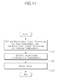
- FIG. 11 is a flowchart illustrating an exemplary method for generating directional sound. The method may be performed by an apparatus for generating directional sound described above.
- a directional sound signal and a non-directional sound signal are generated in operation 1110. That is, in operation 1110, sound signal processing for directional edge loudspeakers and sound signal processing for non-directional internal loudspeakers are performed. In operation 1120, a sound signal for the non-directional loudspeakers is supplied to an internal loudspeaker array having at least one sound source, and a sound signal for the directional loudspeakers is supplied to the edge loudspeakers located at ends of the internal loudspeaker array, wherein the directional loudspeakers includes a sound source having directivity. In operation 1130, the sound signals are synthesized and output.
- the output sound signals of the internal loudspeaker array and the edge loudspeakers are synthesized, and the internal loudspeaker array and the edge loudspeakers are controlled to remove output sound in side directions while maintaining directivity of the sound output toward a specific direction.
- the edge loudspeakers may include a plurality of edge loudspeakers at both ends of the internal loudspeaker array.
- the sound source of the edge loudspeaker may be a high-order directivity sound source.
- the high-frequency pass filtering or the low-frequency pass filtering may be performed on the input sound signal, a multi-channel signal may be generated so that a high-frequency signal is delivered to the internal loudspeaker array and a low-frequency signal is delivered to the internal loudspeaker array or the edge loudspeakers, and each individual loudspeaker of the internal loudspeaker array and edge loudspeakers may be driven.
- a directional sound generating apparatus having a structure of a single array can concentrate sound in all frequency bands, for example, in a low-frequency band and a high-frequency band, on a specific sound zone.
- the apparatus may be provided so that only edge loudspeakers have directivity, so as to minimize the size of the apparatus.
- the directional sound generating apparatus may be implemented using a typical loudspeaker array.
- the methods described above may be recorded, stored, or fixed in one or more computer-readable media that includes program instructions to be implemented by a computer to cause a processor to execute or perform the program instructions.
- the media may also include, alone or in combination with the program instructions, data files, data structures, and the like.
- Examples of computer-readable media include magnetic media, such as hard disks, floppy disks, and magnetic tape; optical media such as CD ROM disks and DVDs; magneto-optical media, such as optical disks; and hardware devices that are specially configured to store and perform program instructions, such as read-only memory (ROM), random access memory (RAM), flash memory, and the like.
- Examples of program instructions include machine code, such as produced by a compiler, and files containing higher level code that may be executed by the computer using an interpreter.
- the described hardware devices may be configured to act as one or more software modules in order to perform the operations and methods described above, or vice versa.
- the computer-readable medium may be distributed among networked computer systems, and the program instructions or computer-readable codes may be stored and executed in a decentralized manner.
- Functional programs, codes, and code segments for implementing the methods described above may be easily inferred by programmers in the art to which the instant disclosure belongs.
- a number of exemplary embodiments have been described above. Nevertheless, it will be understood that various modifications may be made. For example, suitable results may be achieved if the described techniques are performed in a different order and/or if components in a described system, architecture, device, or circuit are combined in a different manner and/or replaced or supplemented by other components or their equivalents. Accordingly, other implementations are within the scope of the following claims.
Landscapes
- Health & Medical Sciences (AREA)
- Otolaryngology (AREA)
- Physics & Mathematics (AREA)
- Engineering & Computer Science (AREA)
- Acoustics & Sound (AREA)
- Signal Processing (AREA)
- General Health & Medical Sciences (AREA)
- Circuit For Audible Band Transducer (AREA)
- Obtaining Desirable Characteristics In Audible-Bandwidth Transducers (AREA)
Applications Claiming Priority (1)
| Application Number | Priority Date | Filing Date | Title |
|---|---|---|---|
| KR1020080125309A KR101298487B1 (ko) | 2008-12-10 | 2008-12-10 | 지향성 음향 발생장치 및 방법 |
Publications (2)
| Publication Number | Publication Date |
|---|---|
| EP2200338A2 true EP2200338A2 (de) | 2010-06-23 |
| EP2200338A3 EP2200338A3 (de) | 2011-09-14 |
Family
ID=41723095
Family Applications (1)
| Application Number | Title | Priority Date | Filing Date |
|---|---|---|---|
| EP09178723A Withdrawn EP2200338A3 (de) | 2008-12-10 | 2009-12-10 | Vorrichtung und Verfahren zur Erzeugung von direktionalem Ton |
Country Status (3)
| Country | Link |
|---|---|
| US (1) | US20100142733A1 (de) |
| EP (1) | EP2200338A3 (de) |
| KR (1) | KR101298487B1 (de) |
Families Citing this family (16)
| Publication number | Priority date | Publication date | Assignee | Title |
|---|---|---|---|---|
| US10679407B2 (en) | 2014-06-27 | 2020-06-09 | The University Of North Carolina At Chapel Hill | Methods, systems, and computer readable media for modeling interactive diffuse reflections and higher-order diffraction in virtual environment scenes |
| US9977644B2 (en) * | 2014-07-29 | 2018-05-22 | The University Of North Carolina At Chapel Hill | Methods, systems, and computer readable media for conducting interactive sound propagation and rendering for a plurality of sound sources in a virtual environment scene |
| EP3089476A1 (de) * | 2015-04-27 | 2016-11-02 | Fraunhofer-Gesellschaft zur Förderung der angewandten Forschung e.V. | Soundsystem |
| US9754575B2 (en) | 2015-08-31 | 2017-09-05 | Panasonic Intellectual Property Corporation Of America | Area-sound reproduction system and area-sound reproduction method |
| US10244317B2 (en) * | 2015-09-22 | 2019-03-26 | Samsung Electronics Co., Ltd. | Beamforming array utilizing ring radiator loudspeakers and digital signal processing (DSP) optimization of a beamforming array |
| CN105681988B (zh) * | 2015-12-30 | 2019-01-22 | 临境声学科技江苏有限公司 | 一种线性阵列拾音器及控制方法 |
| KR20180033771A (ko) * | 2016-09-26 | 2018-04-04 | 엘지전자 주식회사 | 영상표시장치 |
| KR102534768B1 (ko) | 2017-01-03 | 2023-05-19 | 삼성전자주식회사 | 오디오 출력 장치 및 제어방법 |
| US10248744B2 (en) | 2017-02-16 | 2019-04-02 | The University Of North Carolina At Chapel Hill | Methods, systems, and computer readable media for acoustic classification and optimization for multi-modal rendering of real-world scenes |
| US11076230B2 (en) * | 2017-05-16 | 2021-07-27 | Sony Corporation | Speaker array, and signal processing apparatus |
| KR101975022B1 (ko) | 2018-03-07 | 2019-05-03 | 한국기계연구원 | 지향성 음향 장치 |
| KR20200037003A (ko) | 2018-09-28 | 2020-04-08 | 삼성디스플레이 주식회사 | 표시 장치와 그의 구동 방법 |
| KR102174168B1 (ko) | 2018-10-26 | 2020-11-04 | 주식회사 에스큐그리고 | 스피커 음향 특성을 고려한 독립음장 구현 방법 및 구현 시스템 |
| US11317206B2 (en) | 2019-11-27 | 2022-04-26 | Roku, Inc. | Sound generation with adaptive directivity |
| CN114584874B (zh) * | 2020-12-01 | 2024-12-13 | 宏达国际电子股份有限公司 | 扬声模块及穿戴式装置 |
| CN116582803B (zh) * | 2023-06-01 | 2023-10-20 | 广州市声讯电子科技股份有限公司 | 扬声器阵列的自适应控制方法、系统、存储介质及终端 |
Citations (3)
| Publication number | Priority date | Publication date | Assignee | Title |
|---|---|---|---|---|
| US4899390A (en) * | 1986-09-19 | 1990-02-06 | Matsushita Electric Industrial Co., Ltd. | Thin speaker having an enclosure within an open portion and a closed portion |
| US20060126878A1 (en) * | 2003-08-08 | 2006-06-15 | Yamaha Corporation | Audio playback method and apparatus using line array speaker unit |
| US20080101631A1 (en) * | 2006-11-01 | 2008-05-01 | Samsung Electronics Co., Ltd. | Front surround sound reproduction system using beam forming speaker array and surround sound reproduction method thereof |
Family Cites Families (17)
| Publication number | Priority date | Publication date | Assignee | Title |
|---|---|---|---|---|
| JP3205625B2 (ja) * | 1993-01-07 | 2001-09-04 | パイオニア株式会社 | スピーカ装置 |
| JP4445705B2 (ja) * | 2001-03-27 | 2010-04-07 | 1...リミテッド | 音場を作り出す方法および装置 |
| JP2003134589A (ja) | 2001-10-23 | 2003-05-09 | Clarion Co Ltd | スピーカエンクロージャー |
| GB0304126D0 (en) * | 2003-02-24 | 2003-03-26 | 1 Ltd | Sound beam loudspeaker system |
| JP3876850B2 (ja) * | 2003-06-02 | 2007-02-07 | ヤマハ株式会社 | アレースピーカーシステム |
| DE102004060944B4 (de) * | 2003-12-19 | 2011-05-19 | LG Electronics Inc., Kangnam-gu | Anzeigeeinheit für einen Kühlschrank |
| KR20050062075A (ko) * | 2003-12-19 | 2005-06-23 | 엘지전자 주식회사 | 텔레비전 겸용 냉장고의 음향장치 |
| JP4251077B2 (ja) | 2004-01-07 | 2009-04-08 | ヤマハ株式会社 | スピーカ装置 |
| US8170233B2 (en) * | 2004-02-02 | 2012-05-01 | Harman International Industries, Incorporated | Loudspeaker array system |
| US7577265B2 (en) * | 2004-06-29 | 2009-08-18 | Ira Pazandeh | Loudspeaker system providing improved sound presence and frequency response in mid and high frequency ranges |
| JP4949638B2 (ja) * | 2005-04-14 | 2012-06-13 | ヤマハ株式会社 | オーディオ信号供給装置 |
| JP4625756B2 (ja) * | 2005-12-02 | 2011-02-02 | ハーマン インターナショナル インダストリーズ インコーポレイテッド | ラウドスピーカのアレイシステム |
| JP4345784B2 (ja) * | 2006-08-21 | 2009-10-14 | ソニー株式会社 | 音響収音装置及び音響収音方法 |
| KR101427648B1 (ko) * | 2007-10-12 | 2014-08-07 | 삼성전자주식회사 | 어레이 스피커 시스템에서 불균일 방사 패턴을 제거하는방법 및 장치 |
| KR101445075B1 (ko) * | 2007-12-18 | 2014-09-29 | 삼성전자주식회사 | 어레이 스피커를 통한 음장 제어 방법 및 장치 |
| US8379891B2 (en) * | 2008-06-04 | 2013-02-19 | Microsoft Corporation | Loudspeaker array design |
| US8000170B2 (en) * | 2008-11-20 | 2011-08-16 | Analog Devices, Inc. | Systems and methods for acoustic beamforming using discrete or continuous speaker arrays |
-
2008
- 2008-12-10 KR KR1020080125309A patent/KR101298487B1/ko not_active Expired - Fee Related
-
2009
- 2009-12-09 US US12/634,054 patent/US20100142733A1/en not_active Abandoned
- 2009-12-10 EP EP09178723A patent/EP2200338A3/de not_active Withdrawn
Patent Citations (3)
| Publication number | Priority date | Publication date | Assignee | Title |
|---|---|---|---|---|
| US4899390A (en) * | 1986-09-19 | 1990-02-06 | Matsushita Electric Industrial Co., Ltd. | Thin speaker having an enclosure within an open portion and a closed portion |
| US20060126878A1 (en) * | 2003-08-08 | 2006-06-15 | Yamaha Corporation | Audio playback method and apparatus using line array speaker unit |
| US20080101631A1 (en) * | 2006-11-01 | 2008-05-01 | Samsung Electronics Co., Ltd. | Front surround sound reproduction system using beam forming speaker array and surround sound reproduction method thereof |
Also Published As
| Publication number | Publication date |
|---|---|
| KR20100066826A (ko) | 2010-06-18 |
| KR101298487B1 (ko) | 2013-08-22 |
| US20100142733A1 (en) | 2010-06-10 |
| EP2200338A3 (de) | 2011-09-14 |
Similar Documents
| Publication | Publication Date | Title |
|---|---|---|
| EP2200338A2 (de) | Vorrichtung und Verfahren zur Erzeugung von direktionalem Ton | |
| US9219974B2 (en) | Method and apparatus for simultaneously controlling near sound field and far sound field | |
| US9008335B2 (en) | Directional sound generating apparatus and directional speaker array including the same | |
| EP1517580B1 (de) | Elektroakustische Wandlung | |
| JP5405598B2 (ja) | スピーカ | |
| KR101524463B1 (ko) | 어레이 스피커를 통해 음향을 포커싱하는 방법 및 장치 | |
| KR101601196B1 (ko) | 지향성 음향 생성 장치 및 방법 | |
| KR101877323B1 (ko) | 공간 선택 오디오 재생을 위한 디바이스 및 방법 | |
| EP3062536B1 (de) | Lautsprecheranordnung | |
| US10805720B2 (en) | Audio signal processing apparatus and a sound emission apparatus | |
| CN104937660A (zh) | 用于生成声场的方法和系统 | |
| JP2004194315A5 (de) | ||
| JP2008252625A (ja) | 指向性スピーカシステム | |
| CN107925812B (zh) | 具有恒定的宽波束宽度的阵列扬声器 | |
| JP2004363697A (ja) | アレースピーカーシステム | |
| US7299893B2 (en) | Loudspeaker horn and method for controlling grating lobes in a line array of acoustic sources | |
| EP3903509A1 (de) | Kompaktes lautsprechersystem mit gesteuerter richtwirkung | |
| KR101613683B1 (ko) | 음향 방사 패턴 생성 장치 및 방법 | |
| US4437541A (en) | Controlled dispersion speaker configuration | |
| JP4400474B2 (ja) | スピーカアレイ装置 | |
| KR101753065B1 (ko) | 공간 음향 에너지 분포 조절 방법 및 장치 | |
| US7426278B2 (en) | Sound device provided with a geometric and electronic radiation control | |
| KR101825462B1 (ko) | 개인 음향 공간 생성 방법 및 장치 | |
| US8406445B1 (en) | Loudspeaker system with extended constant vertical beamwidth control | |
| US20120321102A1 (en) | Method and apparatus creating a personal sound zone |
Legal Events
| Date | Code | Title | Description |
|---|---|---|---|
| PUAI | Public reference made under article 153(3) epc to a published international application that has entered the european phase |
Free format text: ORIGINAL CODE: 0009012 |
|
| AK | Designated contracting states |
Kind code of ref document: A2 Designated state(s): AT BE BG CH CY CZ DE DK EE ES FI FR GB GR HR HU IE IS IT LI LT LU LV MC MK MT NL NO PL PT RO SE SI SK SM TR |
|
| AX | Request for extension of the european patent |
Extension state: AL BA RS |
|
| PUAL | Search report despatched |
Free format text: ORIGINAL CODE: 0009013 |
|
| AK | Designated contracting states |
Kind code of ref document: A3 Designated state(s): AT BE BG CH CY CZ DE DK EE ES FI FR GB GR HR HU IE IS IT LI LT LU LV MC MK MT NL NO PL PT RO SE SI SK SM TR |
|
| AX | Request for extension of the european patent |
Extension state: AL BA RS |
|
| RIC1 | Information provided on ipc code assigned before grant |
Ipc: H04R 1/34 20060101ALN20110811BHEP Ipc: H04R 1/40 20060101ALN20110811BHEP Ipc: H04R 3/12 20060101AFI20110811BHEP |
|
| 17P | Request for examination filed |
Effective date: 20120220 |
|
| RAP1 | Party data changed (applicant data changed or rights of an application transferred) |
Owner name: SAMSUNG ELECTRONICS CO., LTD. |
|
| 17Q | First examination report despatched |
Effective date: 20160630 |
|
| STAA | Information on the status of an ep patent application or granted ep patent |
Free format text: STATUS: THE APPLICATION IS DEEMED TO BE WITHDRAWN |
|
| 18D | Application deemed to be withdrawn |
Effective date: 20161111 |