EP2199737A1 - 3d camera illumination unit - Google Patents
3d camera illumination unit Download PDFInfo
- Publication number
- EP2199737A1 EP2199737A1 EP08106013A EP08106013A EP2199737A1 EP 2199737 A1 EP2199737 A1 EP 2199737A1 EP 08106013 A EP08106013 A EP 08106013A EP 08106013 A EP08106013 A EP 08106013A EP 2199737 A1 EP2199737 A1 EP 2199737A1
- Authority
- EP
- European Patent Office
- Prior art keywords
- unit
- illumination
- pattern
- illumination unit
- camera
- Prior art date
- Legal status (The legal status is an assumption and is not a legal conclusion. Google has not performed a legal analysis and makes no representation as to the accuracy of the status listed.)
- Granted
Links
Images

Classifications
-
- G—PHYSICS
- G01—MEASURING; TESTING
- G01C—MEASURING DISTANCES, LEVELS OR BEARINGS; SURVEYING; NAVIGATION; GYROSCOPIC INSTRUMENTS; PHOTOGRAMMETRY OR VIDEOGRAMMETRY
- G01C11/00—Photogrammetry or videogrammetry, e.g. stereogrammetry; Photographic surveying
- G01C11/04—Interpretation of pictures
- G01C11/06—Interpretation of pictures by comparison of two or more pictures of the same area
Definitions
- the invention relates to a lighting unit and a method for illuminating a monitoring area of a camera-based sensor according to the preamble of claims 1 and 11, respectively.
- Camera-based sensors are used for a variety of monitoring and automation tasks. The evaluation is made more difficult if the recorded scene is low-contrast, since structural elements are then difficult or impossible to recognize. This can be problematic even with two-dimensional camera systems.
- a true 3D camera records a distance map regardless of the dynamics in the surveillance area or a proper motion, so includes distance values of the depth dimension in the recorded image data.
- One known technique for obtaining distance information is stereoscopy. In this process, at least two cameras record a scene from a staggered perspective, and in the individual images corresponding elements are identified from whose disparity the associated distance can be triangulated.
- Stereoscopic 3D measurement thus works on the basis of contrasty image content, because only a contrasted region allows an assignment of elements. Correspondences can not be determined unambiguously on homogeneous, contour-free and contrast-free surfaces, so that in these areas no depth information can be calculated and gaps in the distance or depth map are created. A dense or full depth map, in which each pixel is filled with the appropriate distance information, therefore allow only fully structured images.
- the monitoring task is to recognize any unauthorized intervention by persons in the vicinity of a danger zone and to eliminate the danger in good time.
- a typical example is the safeguarding of machines or robots near which no one is allowed to come, at least in certain work steps, in order to avoid accidents and injuries.
- the 3D security camera detects such situations and shuts down the machine on time or spends it in a safe position.
- protection areas can be defined more variably and more accurately, and more and more accurate classes can be distinguished from permitted object movements, for example movements of the robot itself or movements of a body part on the dangerous machine in a different depth plane, which is completely harmless in itself, but of one two-dimensional camera can not be differentiated.
- the scenery can be imprinted with the necessary lighting structure, in that an active lighting unit generates a pattern of light and dark areas and therefore also contrast in areas that are structurally and without contrast.
- An active illumination unit generates an illumination pattern by means of a diffractive optical element (DOE).
- DOE diffractive optical element
- a part of the order of magnitude of 1% of the incident laser light is transmitted without bending in the zeroth order.
- a still very concentrated beam leaves the illumination unit, and no solutions are known for removing this beam from the illumination field without further ado.
- such lighting units are either not able to meet requirements for eye safety or the laser protection class, and thus inadmissible for operation, or you have to make do with very little useful light, so that the unbent transmitted beam for eye safety remains uncritical.
- such low-power light does not allow generation of dense depth maps with stereoscopic algorithms over more than shortest ranges.
- the DE 10 2006 001 634 B3 proposes a number of solutions to illuminate the scene taken by a stereoscopic system with a random or pseudo-random pattern.
- masks are used, for example a variable LCD to impart a pattern to transmitted light.
- two grids can be provided, which are shifted against each other and thus produce different moire effects.
- light is expanded in a line with a cylindrical lens and the resulting light line is projected onto the scene via a rotary polygon.
- random intensity modulation then creates a pattern in the direction of rotation. In the direction of the light line itself, however, no structure arises. In addition, it is unfavorable if the pattern generation relies on random intensity modulation.
- the intensity modulation is then no longer available as a degree of freedom for the illumination, and the maximum light output is limited by the modulation in effect to a value corresponding to the expected value of the random number generator, unlike a DOE or the like, where the maximum Light output is redistributed only pattern and thus the total light output benefits the stereoscopic method.
- This object is achieved by a lighting unit according to claim 1 and a method for illuminating a monitoring area of a camera-based sensor according to claim 11.
- the solution according to the invention is based on the principle of producing the pattern in two stages, in which, in a first step, structure arises in a first direction and in a second step structure in a second direction transversely to the first direction.
- transversely initially means only the inclusion of an arbitrary angle other than zero.
- the two directions are perpendicular to one another. This in turn depends on the areas of the scenery and the orientation of the camera in relation to these areas.
- the suitable reference point will be a plane perpendicular to the optical axis.
- the deflection angle varies with the period, for example, the vertical position refers to an excellent deflection angle or the mean of a period of deflection.
- the surveillance area or a region of interest (ROI) of interest is system-adapted and illuminated in a planar manner with a defined pattern.
- the lighting unit can be modular and has a very high lighting efficiency with low optical power dissipation. All components involved have only low optical losses.
- the energetic intensity distribution in the first direction is freely selectable and thus gives great freedom in relation to the resulting illumination pattern.
- a projection lens is not required.
- the optical element is preferably a diffractive optical element (DOE). It therefore has a microstructure which is calculated in such a way that when illuminated with laser light Well-defined pattern in the lighting area is created. Thus diffraction effects redistribute the irradiated energy in the resulting laser line, which extends in the first direction, with any desired structure.
- the DOE can also create a pattern in the second direction, the illumination structure in this direction is then smeared by the periodic deflection and therefore can not be freely selected in the end. According to the invention, an intensity maximum in the zeroth order of the DOE is distributed by the periodic deflection.
- stringent laser protection classes such as 1 or 1 M can be achieved, even if high-power lasers are used at least above a few watts.
- the result is a high-contrast illumination field even in larger ranges, for example, up to 5m and beyond.
- the deflection unit preferably has a mirror wheel, a polygonal mirror wheel or a rotating mirror, wherein, in particular, the mirror surfaces of the deflection unit are designed as a concave mirror with a further preferred toroidal shape.
- Such baffles have long proven useful in laser scanners or bar code scanners, and can provide a sufficiently fast periodic deflection.
- Toric mirror surfaces are suitable for minimizing or even completely compensating for pincushion distortion in the projection plane. The illumination pattern can therefore be reliably generated and evaluated.
- a modulation unit is provided for the light source, so that intensity modulation can be used to predetermine the illumination pattern structure in the second direction.
- intensity modulation can be used to predetermine the illumination pattern structure in the second direction.
- a brightness change is therefore also effected in the second dimension.
- One possibility is to provide the initially striped pattern with a true two-dimensional structure in this way.
- Another preferred possibility is to design the modulation unit to increase the intensity towards the edge of each period, thus giving a U-shaped intensity distribution in the second direction.
- the modulation unit design the modulation unit to increase the intensity towards the edge of each period, thus giving a U-shaped intensity distribution in the second direction.
- a perturbing effect is compensated: towards the edge of each period, the effective deflection speed is higher than in the center because of the changed impact angle. This would be without compensation at the edges in the second Direction decrease the illumination.
- an intensity modulation inverse to the effect is used.
- a further cos 3 error of the camera lenses can be compensated by further increasing the intensity toward the edges, which would otherwise lead to a decrease in brightness at the image edges of the image sensors.
- the image edge brightness decrease can be suppressed and a uniform illumination can be achieved.
- the lighting units according to the invention can advantageously be modularly combined.
- these are arranged relative to each other, that superimpose the illumination patterns in the surveillance area, wherein in particular the first direction of the first illumination unit of the second direction of the second illumination unit and vice versa, the second direction of the first illumination unit the first direction of the second illumination unit corresponds.
- This overlay is more preferably complete, i. Both lighting units illuminate the same area.
- Each lighting unit provides in the associated expansion direction of the optical element for lighting structure. In the end, this results in a freely patternable illumination pattern in both dimensions.
- a synchronization unit is preferably provided, which can synchronize the movement of the deflection unit of the first illumination unit with the movement of the deflection unit of the second illumination unit in synchronism with the generation of a stationary illumination pattern. Due to the synchronization, light lines always overlap at the same deflection angles. In each period, therefore, the same intensity structure is generated, and the illumination pattern is static.
- the deflection units of the first illumination unit and the second illumination unit have an asynchronously adjustable drive for generating a running illumination pattern.
- the samples in the first direction can be decoupled from the second direction, so that the superimposed intensity distribution changes constantly.
- synchronicity can be achieved at least approximately as an alternative to a synchronization unit, in that the two illumination units select a same deflection speed without communication.
- the synchronization unit can also generate targeted asynchronous distractions.
- the synchronicity behavior can be varied from application to application, but also dynamically within an application.
- a camera in particular a 3D stereo camera with at least one lighting unit according to the invention or at least one arrangement of lighting units is provided, which has an evaluation unit which is designed for the application of a stereo algorithm, in which mutually associated sub-areas of at least two cameras Stereocamera recorded images and their distance is calculated on the basis of the disparity.
- This camera benefits from the inventive bright and high contrast illuminated scenery and works therefore with very high accuracy and reliability.
- the camera is preferably designed as a security camera, wherein the evaluation unit is further adapted to generate a dense depth map to detect inadmissible interference with the surveillance area and then to generate a shutdown signal, a safety output is provided, via which the security camera a shutdown signal to a monitored machine can spend.
- the dense depth map allows reliable safety-related three-dimensional monitoring regardless of scenery and ambient light.
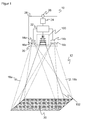
- FIG. 1 shows in a schematic three-dimensional representation of the general structure of a 3D camera according to the invention 10 according to the stereoscopic principle, which is used for example for safety monitoring of a room area 12.
- Two camera modules are mounted in a known fixed distance from each other and each take pictures of the space area 12.
- an image sensor 14a, 14b is provided, usually a matrix-shaped recording chip, which receives a rectangular pixel image, for example a CCD or a CMOS sensor.
- an objective with imaging optics which are shown as lenses 16a, 16b and can be realized in practice as any known imaging optics.
- the viewing angle of these optics is in FIG. 1 represented by dashed lines, each forming a viewing pyramid 18a, 18b.
- a lighting unit 100 is shown, this spatial arrangement is to be understood only as an example and the lighting unit 100 may also be arranged asymmetrically or even outside the security camera 3D.
- the illumination unit 100 according to the invention generates a structured illumination pattern 20 in the illumination region 102 in the spatial region 12 and will be described below in various embodiments in connection with FIGS FIGS. 2 to 4 explained in more detail.
- a controller 22 is connected to the two image sensors 14a, 14b and the illumination unit 100.
- the structured illumination pattern 20 is generated and varied in its structure or intensity as needed, and the controller 22 receives image data from the image sensors 14a, 14b. From this image data, the controller 22 calculates three-dimensional image data (distance image, depth map) of the spatial region 12 by means of a stereoscopic disparity estimation.
- the structured illumination pattern 20 thereby provides good contrast and a clearly assignable structure of each pixel in the illuminated spatial region 12.
- the self-dissimilarity being the at least local, better global lack of translational symmetries, so that no apparent shifts of picture elements in the images respectively taken from different perspectives are recognized due to the same illumination pattern elements Cause disparity estimation.
- two image sensors 14a, 14b there is a known problem that structures along the epipolar line can not be used for the disparity estimation, because here no triangulation angle occurs or, in other words, the system can not locally distinguish whether the structure in the two images due to the perspective shifted against each other or whether only an indistinguishable other part of the same, aligned parallel to the base of the stereo system structure is compared.
- one or more other camera modules can be used, which are arranged offset from the connecting line of the original two camera modules.
- the space area 12 monitored by the security sensor 10 may contain known and unexpected objects. This may, for example, be a robot arm, a machine, an operator and others.
- the room area 12 provides access to a source of danger, be it because it is an access area or because a dangerous machine is in the room area 12 itself.
- one or more virtual protection and warning fields can be configured. Due to the three-dimensional evaluation, it is also possible to define these fields three-dimensionally, so that a great deal of flexibility arises.
- the controller 22 evaluates the three-dimensional image data for impermissible interventions. For example, the evaluation rules may stipulate that no object may exist in protected fields at all. More flexible evaluation rules provide differentiation between allowed and non-permitted objects, such as trajectories, patterns or contours, speeds or general workflows that are both learned in advance as well as evaluated on the basis of assessments, heuristics or classifications during operation.
- the controller 22 detects an impermissible intervention in a protective field, it is integrated via a warning or disconnection device 24, which in turn is integrated into the controller 22 may be issued a warning or hedged the source of danger, for example, stopped a robot arm or other machine.
- Safety-relevant signals that is, in particular the switch-off signal, are output via a safety output 26 (OSSD, Output Signal Switching Device). It depends on the application, whether a warning is sufficient, or it is a two-stage protection provided in the first warned and is turned off only with continued object engagement or even deeper penetration. Instead of a shutdown, the appropriate response may also be the immediate transfer to a safe parking position.
- the senor 10 is designed fail-safe. This means, inter alia, that the sensor 10 can test itself in cycles below the required response time, in particular also detects defects of the illumination unit 100 and thus ensures that the illumination pattern 20 is available in an expected minimum intensity, and that the safety output 26 and the Warn - or shutdown 24 safe, for example, two channels are designed. Likewise, the controller 22 is self-confident, thus evaluating two-channel or uses algorithms that can check themselves. Such regulations are standardized for general non-contact protective devices in EN 61496-1 or IEC 61496. A corresponding standard for security cameras is in preparation.
- the security camera 10 is surrounded by a housing 28 and protected. Through a windscreen 30, light can pass in and out of the space area 12.
- the windshield 30 has filter characteristics which are matched to the transmission frequency of the illumination unit 100.
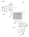
- FIG. 2 shows a first embodiment of the lighting unit 100 according to the invention.
- like reference numerals designate the same features.
- the perspective of the representation is simplified in order to make the resulting illumination pattern 104 better recognizable, but basically the illumination pattern 20 of the FIG. 1 equivalent.
- the light source 106 is a semiconductor diode, such as an LED, a VCSEL (Vertical Cavity Surface Emitting Laser) or a laser diode.
- a laser light source is required.
- the emitted light is focused in an optic, such as a converging lens 108, to infinity and directed to a pattern-generating optical element 110, which is the Light widens in one direction.
- a pattern-generating optical element 110 can also expand and structure the incident light in the transverse direction, even such a light pattern is referred to in the following simplifying as a light line ,
- a DOE may be used whose microstructure generates a predefined structured laser line.
- this laser line can assume virtually any desired pattern, ranging from general inhomogeneities to a defined dot or line pattern with different individual thicknesses of the dot or line elements.
- the structured light line is incident on a periodic deflection unit 112, such as a rotating polygon mirror wheel or rotating mirror, and is projected into the monitoring area 12.
- the light line is therefore deflected periodically in the X direction perpendicular to the lateral Y direction and thus generates the two-dimensional illumination pattern 104 in the projection plane.
- the deflection or scanning direction is preferably chosen transversely to the epipolar line of the 3D camera 10, thus in the direction of Epipolarline structuring by the pattern-generating optical element 110 is maintained.
- the resulting pattern is initially a stripe pattern, so it changes in the X direction.
- intensity modulation ie modulation of the emission power of the light source 106
- an additional brightness change in the X direction can be impressed.
- modulations may, for example, control the controller 22.
- two-dimensionally structured illumination patterns 104 which offer even stronger local contrast differences.
- intensity modulations can be used above all to compensate for inhomogeneities of the illumination and the image. Due to the opto-geometric structure, the path velocity of the projected lines increases from the center of the image toward the outside, or in other words from the center of a mirror surface the deflection unit 12 to the edges towards clearly. This causes a corresponding significant reduction of the irradiance towards the edge of the image.
- FIG. 3 illustrates how the intensity can be varied from the beginning x 0 to the end x max of each deflection period to compensate for this effect.
- An intensity I 1 stands for the maximum possible optical output power of the light source 106, so that a relative intensity is plotted.
- the light source is corresponding FIG. 3 Depending on the location modulated and their transmission power to the edge regions of the projection plane with the illumination pattern 104 continuously raised to ensure a homogeneous in their effective irradiance lighting.
- the facets or mirror surfaces of the deflection unit 112 can be formed as a concave mirror.
- These concave mirrors preferably have a toric shape in which the scan axis can also assume the radius infinitely. This feature significantly reduces the pincushion distortion in the projection plane of the illumination pattern 104.
- a typical scan frequency or frame rate is 1 KHz, the modulation of the laser emission power typically at 500 KHz.
- a polygon mirror wheel 12 has a speed of 125 revolutions per second and spans a projection angle of 90 °. With such an arrangement, a large variance in light-dark ratios can be set very easily. The contrasts become sharper and increase the overall performance of the 3D camera 10.
- FIG. 4 shows a further embodiment for generating structure in the X direction, that is, a total of a two-dimensionally structured illumination pattern 104 without intensity modulation.
- An additional intensity modulation can then be used alone for the FIG. 3 described compensation is and will be used no longer needed for pattern generation itself.
- a plurality of, in this case, two illumination units 100a, 100b are modularly combined to form a lighting unit 200.
- Each individual module 100a, 100b is constructed analogously to the illumination units 100 described above.
- the illumination patterns of the two modules 100a, 100b are superimposed on the two-dimensionally structured pattern 104.
- the modules 100a, 100b are arranged transversely to one another, so that the structured light line of the first module 100a is transverse to the structured light line of the second module 100b.
- the deflection units 112a, 112b run asynchronously with each other, the brightness distribution is constantly varied, the frequency of these variations depending on the degree of asynchronicity.
- the structured illumination according to the invention serves not only in security cameras, but also for general monitoring tasks, including two-dimensional cameras for increasing the contrast. However, it shows special advantages in connection with stereoscopic spatial image recording methods.
- the resulting dense depth maps in turn can be used in other applications such as automation technology, they are particularly suitable for safety technology, where reliable evaluations are a prerequisite of practical use.
Abstract
Description
Die Erfindung betrifft eine Beleuchtungseinheit und ein Verfahren zur Beleuchtung eines Überwachungsbereichs eines kamerabasierten Sensors nach dem Oberbegriff von Anspruch 1 beziehungsweise 11.The invention relates to a lighting unit and a method for illuminating a monitoring area of a camera-based sensor according to the preamble of claims 1 and 11, respectively.
Kamerabasierte Sensoren werden für eine Vielzahl von Überwachungs- und Automatisierungsaufgaben eingesetzt. Dabei wird die Auswertung erschwert, wenn die aufgenommene Szenerie kontrastschwach ist, da Strukturelemente dann nur schwer oder gar nicht erkannt werden können. Dies kann bereits bei zweidimensionalen Kamerasystemen problematisch werden.Camera-based sensors are used for a variety of monitoring and automation tasks. The evaluation is made more difficult if the recorded scene is low-contrast, since structural elements are then difficult or impossible to recognize. This can be problematic even with two-dimensional camera systems.
Es besteht aber für viele Anwendungen sogar der Wunsch, dreidimensionale Bilddaten auszuwerten. In dynamischen Aufbauten kann dies durch Bewegung des Messobjekts, etwa im Materialfluss, beziehungsweise durch Bewegen oder Verschwenken einer zweidimensionalen scannenden oder 2D-kamerabasierten Sensoreinheit erreicht werden. Dies ist wegen der erforderlichen Bewegung keine vollwertige dreidimensionale Messtechnik.However, for many applications there is even the desire to evaluate three-dimensional image data. In dynamic constructions, this can be achieved by movement of the measurement object, for example in the material flow, or by moving or pivoting a two-dimensional scanning or 2D camera-based sensor unit. This is not a full-fledged three-dimensional measurement technique because of the required movement.
Eine echte 3D-Kamera zeichnet eine Entfernungskarte unabhängig von der Dynamik im Überwachungsbereich oder einer Eigenbewegung auf, bezieht also Abstandswerte der Tiefendimension in die aufgenommenen Bilddaten ein. Ein bekanntes Verfahren für die Gewinnung der Abstandsinformationen ist die Stereoskopie. Dabei wird mit mindestens zwei Kameras eine Szenerie aus versetzter Perspektive aufgenommen, und in den Einzelbildern werden korrespondierende Elemente identifiziert, aus deren Disparität die zugehörige Entfernung trianguliert werden kann.A true 3D camera records a distance map regardless of the dynamics in the surveillance area or a proper motion, so includes distance values of the depth dimension in the recorded image data. One known technique for obtaining distance information is stereoscopy. In this process, at least two cameras record a scene from a staggered perspective, and in the individual images corresponding elements are identified from whose disparity the associated distance can be triangulated.
Stereoskopische 3D-Messung arbeitet somit auf Basis von kontrastbehafteten Bildinhalten, weil nur ein kontrastierter Bereich eine Zuordnung von Elementen erlaubt. Auf homogenen, kontur- und kontrastlosen Flächen können Korrespondenzen nicht eindeutig bestimmt werden, so dass in diesen Bereichen keine Tiefeninformation berechenbar ist und Lücken in der Entfernungs- oder Tiefenkarte entstehen. Eine dichte oder füllige Tiefenkarte, bei der jeder Bildpunkt mit einer zutreffenden Abstandsinformation belegt ist, ermöglichen deshalb nur vollständig strukturierte Bilder.Stereoscopic 3D measurement thus works on the basis of contrasty image content, because only a contrasted region allows an assignment of elements. Correspondences can not be determined unambiguously on homogeneous, contour-free and contrast-free surfaces, so that in these areas no depth information can be calculated and gaps in the distance or depth map are created. A dense or full depth map, in which each pixel is filled with the appropriate distance information, therefore allow only fully structured images.
Besonders bei Anwendungen in der Sicherheitstechnik sind Lücken in den Tiefenkarten nicht hinnehmbar. Hier ist die Überwachungsaufgabe, jeden unzulässigen Eingriff von Personen in die Nähe eines Gefahrenbereichs zu erkennen und die Gefahr dann rechtzeitig zu beseitigen. Ein typisches Beispiel sind Absicherungen von Maschinen oder Robotern, in deren Nähe zumindest in gewissen Arbeitsschritten niemand kommen darf, um Unfälle und Verletzungen zu vermeiden. Die 3D-Sicherheitskamera erkennt solche Situationen und schaltet die Maschine rechtzeitig ab oder verbringt sie in eine sichere Position. Mit Hilfe der Tiefeninformationen können Schutzbereiche variabler und genauer festgelegt und mehr und genauere Klassen von erlaubten Objektbewegungen unterschieden werden, also beispielsweise Bewegungen des Roboters selbst oder Vorbeibewegungen eines Körperteils an der gefährlichen Maschine in einer unterschiedlichen Tiefenebene, die an sich völlig ungefährlich ist, aber von einer zweidimensionalen Kamera nicht differenziert werden kann.Especially in applications in safety technology, gaps in the depth maps are unacceptable. Here, the monitoring task is to recognize any unauthorized intervention by persons in the vicinity of a danger zone and to eliminate the danger in good time. A typical example is the safeguarding of machines or robots near which no one is allowed to come, at least in certain work steps, in order to avoid accidents and injuries. The 3D security camera detects such situations and shuts down the machine on time or spends it in a safe position. With the aid of the depth information, protection areas can be defined more variably and more accurately, and more and more accurate classes can be distinguished from permitted object movements, for example movements of the robot itself or movements of a body part on the dangerous machine in a different depth plane, which is completely harmless in itself, but of one two-dimensional camera can not be differentiated.
Jegliche Lücken oder Fehler in der Tiefenkarte, also Bereiche, in denen die Korrespondenz nicht oder falsch festgestellt wird und für die entsprechend kein oder ein falscher Abstandswert vorliegt, gefährden dann die Gesundheit von Bedienpersonal oder führen zumindest zu an sich unnötigen Abschaltungen und damit Ausfallzeiten. Dabei sollen im Idealfall bereits Eingriffe durch Fremdobjekte von der Größe eines Fingers sicher erkannt werden.Any gaps or errors in the depth map, ie areas in which the correspondence is not detected or incorrect and for which there is no or a wrong distance value, then endanger the health of operating personnel or at least lead to unnecessary shutdowns and thus downtime. In the ideal case, interventions by foreign objects the size of a finger should already be reliably detected.
Passive Stereomesssysteme, die ihre Abstandsmessung allein aufgrund der natürlicherweise in den Bildern vorhandenen Merkmale durchführen und demnach keinen Einfluss auf die Qualität und Dichte dieser Merkmale haben, lassen daher keine zuverlässige Sicherheitsfunktion zu. Zu einer möglichen Struktur- oder Kontrastschwäche tritt hier schlicht mangelnde Helligkeit als mögliche Fehlerquelle hinzu. Selbstverständlich ist für eine vorgegebene Anwendung möglich, die Szenerie entsprechend auszuwählen oder zu präparieren, aber dies ist umständlich und schafft zusätzliche Abhängigkeiten. Eine derartige passive Lösung ist beispielsweise in der
Um die gewünschten dichten Tiefenkarten zu erhalten, kann der Szenerie die notwendige Beleuchtungsstruktur aufgeprägt werden, indem eine aktive Beleuchtungseinheit ein Muster aus hellen und dunklen Bereichen und damit Kontrast auch in an sich struktur- und kontrastlosen Bereichen erzeugt.In order to obtain the desired dense depth maps, the scenery can be imprinted with the necessary lighting structure, in that an active lighting unit generates a pattern of light and dark areas and therefore also contrast in areas that are structurally and without contrast.
In der
Die
Es ist daher Aufgabe der Erfindung, eine lichtstarke Beleuchtungseinheit für einen kamerabasierten Sensor mit gutem Kontrast und hohen Transmissioneigenschaften, also geringen optischen Verlusten anzugeben.It is therefore an object of the invention to provide a high-intensity illumination unit for a camera-based sensor with good contrast and high transmission properties, ie low optical losses.
Diese Aufgabe wird durch eine Beleuchtungseinheit gemäß Anspruch 1 und ein Verfahren zur Beleuchtung eines Überwachungsbereichs eines kamerabasierten Sensors gemäß Anspruch 11 gelöst.This object is achieved by a lighting unit according to claim 1 and a method for illuminating a monitoring area of a camera-based sensor according to claim 11.
Die erfindungsgemäße Lösung geht von dem Prinzip aus, das Muster zweistufig zu erzeugen, in dem in einem ersten Schritt Struktur in einer ersten Richtung und in einem zweiten Schritt Struktur in einer zweiten Richtung quer zu der ersten Richtung entsteht. Dabei bedeutet quer zunächst nur Einschluss eines beliebigen Winkels ungleich Null. Bevorzugt ist, wenn in dem entstehenden zweidimensionalen Muster die beiden Richtungen senkrecht zueinander stehen. Das wiederum hängt von den Flächen der Szenerie und der Orientierung der Kamera gegenüber diesen Flächen ab. Gewöhnlich wird der geeignete Bezugspunkt eine Ebene senkrecht zur optischen Achse sein. Dabei variiert natürlich der Ablenkungswinkel mit der Periode, die senkrechte Lage bezieht sich beispielsweise auf einen ausgezeichneten Ablenkungswinkel oder das Mittel einer Periode der Ablenkung.The solution according to the invention is based on the principle of producing the pattern in two stages, in which, in a first step, structure arises in a first direction and in a second step structure in a second direction transversely to the first direction. In this case, transversely initially means only the inclusion of an arbitrary angle other than zero. It is preferred if, in the resulting two-dimensional pattern, the two directions are perpendicular to one another. This in turn depends on the areas of the scenery and the orientation of the camera in relation to these areas. Usually the suitable reference point will be a plane perpendicular to the optical axis. Of course, the deflection angle varies with the period, for example, the vertical position refers to an excellent deflection angle or the mean of a period of deflection.
Soweit nach dem ersten Schritt noch aus Sicht des Augenschutzes bedenkliche Intensitätsmaxima vorhanden sind, werden diese im zweiten Schritt verschmiert und damit entschärft. Mit der erfindungsgemäßen Lösung wird der Überwachungsbereich oder ein interessierender Teilbereich (ROI, region of interest) systemangepasst und flächig mit einem definierten Muster ausgeleuchtet. Die Beleuchtungseinheit kann modular aufgebaut sein und hat eine sehr hohe Beleuchtungseffizienz mit nur geringer optischer Verlustleistung. Alle beteiligten Komponenten haben nur geringe optische Verluste. Die energetische Intensitätsverteilung in der ersten Richtung ist frei wählbar und gibt damit große Freiheiten in Bezug auf das entstehende Beleuchtungsmuster. Ein Projektionsobjektiv ist nicht erforderlich.If after the first step, from the point of view of eye protection, alarming intensity maxima are present, they are blurred in the second step and thus defused. With the solution according to the invention, the surveillance area or a region of interest (ROI) of interest is system-adapted and illuminated in a planar manner with a defined pattern. The lighting unit can be modular and has a very high lighting efficiency with low optical power dissipation. All components involved have only low optical losses. The energetic intensity distribution in the first direction is freely selectable and thus gives great freedom in relation to the resulting illumination pattern. A projection lens is not required.
Das optische Element ist bevorzugt ein diffraktives optisches Element (DOE). Es weist also eine Mikrostruktur auf, die so berechnet ist, dass bei Anstrahlen mit Laserlicht ein wohldefiniertes Muster im Beleuchtungsbereich entsteht. Damit wird durch Beugungseffekte die eingestrahlte Energie in der entstehenden Laserlinie, die sich in der ersten Richtung erstreckt, mit einer beliebigen gewünschten Struktur umverteilt. Das DOE kann auch in der zweiten Richtung ein Muster erzeugen, Beleuchtungsstruktur in dieser Richtung wird anschließend durch die periodische Ablenkung verschmiert und ist daher im Endeffekt nicht frei wählbar. Erfindungsgemäß wird ein Intensitätsmaximum in nullter Ordnung des DOE durch die periodische Ablenkung verteilt. Damit sind strenge Laserschutzklassen wie 1 oder 1 M realisierbar, auch wenn Laser hoher Leistung zumindest oberhalb einiger Watt eingesetzt werden. Es entsteht ein kontraststarkes Beleuchtungsfeld auch in größeren Reichweiten beispielsweise bis zu 5m und darüber hinaus.The optical element is preferably a diffractive optical element (DOE). It therefore has a microstructure which is calculated in such a way that when illuminated with laser light Well-defined pattern in the lighting area is created. Thus diffraction effects redistribute the irradiated energy in the resulting laser line, which extends in the first direction, with any desired structure. The DOE can also create a pattern in the second direction, the illumination structure in this direction is then smeared by the periodic deflection and therefore can not be freely selected in the end. According to the invention, an intensity maximum in the zeroth order of the DOE is distributed by the periodic deflection. This means that stringent laser protection classes such as 1 or 1 M can be achieved, even if high-power lasers are used at least above a few watts. The result is a high-contrast illumination field even in larger ranges, for example, up to 5m and beyond.
Die Ablenkeinheit weist bevorzugt ein Spiegelrad, ein Polygonspiegelrad oder einen Drehspiegel auf, wobei insbesondere die Spiegelflächen der Ablenkeinheit als Hohlspiegel mit nochmals bevorzugt torischer Form ausgebildet sind. Derartige Ablenkeinheiten haben sich in Laserscannern oder Barcodescannern seit langem bewährt, und sie können für eine hinreichend schnelle periodische Ablenkung sorgen. Torische Spiegelflächen sind geeignet, um eine Kissenverzeichnung in der Projektionsebene zu minimieren oder ganz auszugleichen. Das Beleuchtungsmuster kann daher zuverlässig erzeugt und ausgewertet werden.The deflection unit preferably has a mirror wheel, a polygonal mirror wheel or a rotating mirror, wherein, in particular, the mirror surfaces of the deflection unit are designed as a concave mirror with a further preferred toroidal shape. Such baffles have long proven useful in laser scanners or bar code scanners, and can provide a sufficiently fast periodic deflection. Toric mirror surfaces are suitable for minimizing or even completely compensating for pincushion distortion in the projection plane. The illumination pattern can therefore be reliably generated and evaluated.
Bevorzugt ist eine Modulationseinheit für die Lichtquelle vorgesehen, so dass durch Intensitätsmodulation dem Beleuchtungsmuster Struktur in der zweiten Richtung vorgebbar ist. Zusätzlich zu einer Beleuchtungsstruktur in der ersten Richtung durch das optische Element wird also auch in der zweiten Dimension eine Helligkeitsänderung bewirkt. Dabei ist eine Möglichkeit, auf diese Weise das zunächst streifige Muster mit echt zweidimensionaler Struktur zu versehen.Preferably, a modulation unit is provided for the light source, so that intensity modulation can be used to predetermine the illumination pattern structure in the second direction. In addition to a lighting structure in the first direction through the optical element, a brightness change is therefore also effected in the second dimension. One possibility is to provide the initially striped pattern with a true two-dimensional structure in this way.
Eine andere bevorzugte Möglichkeit ist, die Modulationseinheit dafür auszubilden, die Intensität zum Rande jeder Periode hin anzuheben und somit eine U-förmige Intensitätsverteilung in der zweiten Richtung vorzugeben. So entsteht also zunächst kein eigentliches Beleuchtungsmuster in der zweiten Richtung, obwohl denkbar wäre, die U-förmige Intensitätsverteilung zugleich mit einer mustererzeugenden Modulation zu überlagern. Stattdessen wird ein Störeffekt ausgeglichen: Zum Rand jeder Periode hin ist die effektive Ablenkgeschwindigkeit wegen des veränderten Auftreffwinkels höher als in der Mitte. Damit würde ohne Kompensation an den Rändern in der zweiten Richtung die Beleuchtungsstärke abnehmen. Um diesen unerwünschten Effekt zu kompensieren, wird mit einer zu dem Effekt inversen Intensitätsmodulation gearbeitet. Durch diese Maßnahme kann durch weitere Anhebung der Intensität zu den Rändern hin zugleich ein cos3-Fehler der Kameraobjektive kompensiert werden, der sonst zu einem Helligkeitsabfall an den Bildrändern der Bildsensoren führen würde. Durch gezielte und einfache Energieumverteilung kann so der Bildrandhelligkeitsabfall unterdrückt und eine gleichmäßige Ausleuchtung erreicht werden.Another preferred possibility is to design the modulation unit to increase the intensity towards the edge of each period, thus giving a U-shaped intensity distribution in the second direction. Thus, initially no actual illumination pattern is formed in the second direction, although it would be conceivable to superimpose the U-shaped intensity distribution at the same time with a pattern-generating modulation. Instead, a perturbing effect is compensated: towards the edge of each period, the effective deflection speed is higher than in the center because of the changed impact angle. This would be without compensation at the edges in the second Direction decrease the illumination. In order to compensate for this undesired effect, an intensity modulation inverse to the effect is used. As a result of this measure, a further cos 3 error of the camera lenses can be compensated by further increasing the intensity toward the edges, which would otherwise lead to a decrease in brightness at the image edges of the image sensors. Through targeted and simple energy redistribution, the image edge brightness decrease can be suppressed and a uniform illumination can be achieved.
Die erfindungsgemäßen Beleuchtungseinheiten können vorteilhafterweise modular kombiniert werden. In einer bevorzugten Anordnung von mindestens einer ersten Beleuchtungseinheit und einer zweiten Beleuchtungseinheit werden diese so zueinander angeordnet, dass sich die Beleuchtungsmuster in dem Überwachungsbereich überlagern, wobei insbesondere die erste Richtung der ersten Beleuchtungseinheit der zweiten Richtung der zweiten Beleuchtungseinheit und umgekehrt die zweite Richtung der ersten Beleuchtungseinheit der ersten Richtung der zweiten Beleuchtungseinheit entspricht. Diese Überlagerung ist noch bevorzugter vollständig, d.h. beide Beleuchtungseinheiten leuchten denselben Bereich aus. Jede Beleuchtungseinheit sorgt in der zugehörigen Aufweitungsrichtung des optischen Elements für Beleuchtungsstruktur. Im Endeffekt ergibt sich daraus ein in beiden Dimensionen frei strukturierbares Beleuchtungsmuster.The lighting units according to the invention can advantageously be modularly combined. In a preferred arrangement of at least one first illumination unit and a second illumination unit, these are arranged relative to each other, that superimpose the illumination patterns in the surveillance area, wherein in particular the first direction of the first illumination unit of the second direction of the second illumination unit and vice versa, the second direction of the first illumination unit the first direction of the second illumination unit corresponds. This overlay is more preferably complete, i. Both lighting units illuminate the same area. Each lighting unit provides in the associated expansion direction of the optical element for lighting structure. In the end, this results in a freely patternable illumination pattern in both dimensions.
In der Anordnung ist bevorzugt eine Synchronisierungseinheit vorgesehen, welche die Bewegung der Ablenkeinheit der ersten Beleuchtungseinheit mit der Bewegung der Ablenkeinheit der zweiten Beleuchtungseinheit synchron zur Erzeugung eines stehenden Beleuchtungsmusters synchronisieren kann. Durch die Synchronisation überlagern sich stets Lichtlinien zu gleichen Ablenkungswinkeln. In jeder Periode wird also dieselbe Intensitätsstruktur erzeugt, und das Beleuchtungsmuster ist statisch.In the arrangement, a synchronization unit is preferably provided, which can synchronize the movement of the deflection unit of the first illumination unit with the movement of the deflection unit of the second illumination unit in synchronism with the generation of a stationary illumination pattern. Due to the synchronization, light lines always overlap at the same deflection angles. In each period, therefore, the same intensity structure is generated, and the illumination pattern is static.
Alternativ weisen die Ablenkeinheiten der ersten Beleuchtungseinheit und der zweiten Beleuchtungseinheit einen zueinander asynchron einstellbaren Antrieb zur Erzeugung eines laufenden Beleuchtungsmusters auf. Damit können die Abtastungen in der ersten Richtung von der zweiten Richtung entkoppelt projiziert werden, so dass die überlagerte Intensitätsverteilung sich ständig ändert. Dabei kann Synchronizität alternativ zu einer Synchronisierungseinheit zumindest näherungsweise auch erreicht werden, indem die beiden Beleuchtungseinheiten ohne Kommunikation eine gleiche Ablenkungsgeschwindigkeit wählen. Umgekehrt kann auch die Synchronisierungseinheit gezielt asynchrone Ablenkungen erzeugen. Das Synchronizitätsverhalten kann von Anwendung zu Anwendung, aber auch dynamisch innerhalb einer Anwendung varriert werden.Alternatively, the deflection units of the first illumination unit and the second illumination unit have an asynchronously adjustable drive for generating a running illumination pattern. Thus, the samples in the first direction can be decoupled from the second direction, so that the superimposed intensity distribution changes constantly. In this case, synchronicity can be achieved at least approximately as an alternative to a synchronization unit, in that the two illumination units select a same deflection speed without communication. Conversely, the synchronization unit can also generate targeted asynchronous distractions. The synchronicity behavior can be varied from application to application, but also dynamically within an application.
In Weiterbildung der Erfindung ist eine Kamera, insbesondere 3D-Stereokamera mit mindestens einer erfindungsgemäßen Beleuchtungseinheit oder mindestens einer Anordnung von Beleuchtungseinheiten vorgesehen, die eine Auswertungseinheit aufweist, welche für die Anwendung eines Stereoalgorithmus ausgebildet ist, in dem einander zugehörige Teilbereiche der von mindestens zwei Kameras der Stereokamera aufgenommenen Bilder erkannt werden und deren Abstand anhand der Disparität berechnet wird. Diese Kamera profitiert von der erfindungsgemäß lichtstark und kontrastreich beleuchteten Szenerie und arbeitet daher mit besonders hoher Genauigkeit und Zuverlässigkeit.In a further development of the invention, a camera, in particular a 3D stereo camera with at least one lighting unit according to the invention or at least one arrangement of lighting units is provided, which has an evaluation unit which is designed for the application of a stereo algorithm, in which mutually associated sub-areas of at least two cameras Stereocamera recorded images and their distance is calculated on the basis of the disparity. This camera benefits from the inventive bright and high contrast illuminated scenery and works therefore with very high accuracy and reliability.
Die Kamera ist bevorzugt als Sicherheitskamera ausgebildet, wobei die Auswertungseinheit weiterhin dafür ausgebildet ist, eine dichte Tiefenkarte zu erzeugen, unzulässige Eingriffe in den Überwachungsbereich zu erkennen und daraufhin ein Abschaltsignal zu erzeugen, wobei ein Sicherheitsausgang vorgesehen ist, über welchen die Sicherheitskamera ein Abschaltsignal an eine überwachte Maschine ausgeben kann. Die dichte Tiefenkarte erlaubt eine zuverlässige sicherheitstechnische dreidimensionale Überwachung unabhängig von Szenerie und Umgebungslicht.The camera is preferably designed as a security camera, wherein the evaluation unit is further adapted to generate a dense depth map to detect inadmissible interference with the surveillance area and then to generate a shutdown signal, a safety output is provided, via which the security camera a shutdown signal to a monitored machine can spend. The dense depth map allows reliable safety-related three-dimensional monitoring regardless of scenery and ambient light.
Das erfindungsgemäße Verfahren kann auf ähnliche Weise weitergebildet werden und zeigt dabei ähnliche Vorteile. Derartige vorteilhafte Merkmale sind beispielhaft, aber nicht abschließend in den sich an die unabhängigen Ansprüche anschließenden Unteransprüchen beschrieben.The method according to the invention can be developed in a similar manner and shows similar advantages. Such advantageous features are described by way of example but not exhaustively in the subclaims following the independent claims.
Die Erfindung wird nachstehend auch hinsichtlich weiterer Merkmale und Vorteile beispielhaft anhand von Ausführungsformen und unter Bezug auf die beigefügte Zeichnung näher erläutert. Die Abbildungen der Zeichnung zeigen in:
- Fig. 1
- eine schematische räumliche Gesamtdarstellung einer Ausführungsform einer erfindungsgemäßen Beleuchtungseinheit, die einen Raumbereich mit einem strukturierten Muster beleuchtet, in einer 3D-Sicherheitskamera;
- Fig. 2
- eine schematische Darstellung einer Ausführungsform einer einzelnen erfindungsgemäßen Beleuchtungseinheit mit einer periodischen Ablenkeinheit;
- Fig.3
- eine Darstellung einer Intensitätsmodulation in einer weiteren Ausführungsform der erfindungsgemäßen Beleuchtungseinheit zur Verhinderung von Bildrandhelligkeitsabfall; und
- Fig. 4
- eine schematische Darstellung einer Anordnung von zwei erfindungsgemäßen Beleuchtungseinheiten mit überlagertem Beleuchtungsfeld.
- Fig. 1
- a schematic overall view of an embodiment of a lighting unit according to the invention, which illuminates a space area with a structured pattern, in a 3D security camera;
- Fig. 2
- a schematic representation of an embodiment of a single lighting unit according to the invention with a periodic deflection unit;
- Figure 3
- a representation of an intensity modulation in a further embodiment of the illumination unit according to the invention for preventing image edge brightness drop; and
- Fig. 4
- a schematic representation of an arrangement of two lighting units according to the invention with superimposed illumination field.
In der Mitte zwischen den beiden Bildsensoren 14a, 14b ist eine Beleuchtungseinheit 100 dargestellt, wobei diese räumliche Anordnung nur als Beispiel zu verstehen ist und die Beleuchtungseinheit 100 ebenso asymmetrisch oder sogar außerhalb der Sicherheitskamera 3D angeordnet sein kann. Die erfindungsgemäße Beleuchtungseinheit 100 erzeugt in einem Beleuchtungsbereich 102 ein strukturiertes Beleuchtungsmuster 20 in dem Raumbereich 12 und wird weiter unten in verschiedenen Ausführungsformen im Zusammenhang mit den
Mit den beiden Bildsensoren 14a, 14b und der Beleuchtungseinheit 100 ist eine Steuerung 22 verbunden. Mittels der Steuerung 22 wird das strukturierte Beleuchtungsmuster 20 erzeugt und bei Bedarf in seiner Struktur oder Intensität variiert, und die Steuerung 22 empfängt Bilddaten der Bildsensoren 14a, 14b. Aus diesen Bilddaten berechnet die Steuerung 22 mit Hilfe einer stereoskopischen Disparitätsschätzung dreidimensionale Bilddaten (Entfernungsbild, Tiefenkarte) des Raumbereichs 12. Das strukturierte Beleuchtungsmuster 20 sorgt dabei für einen guten Kontrast und eine eindeutig zuordenbare Struktur jedes Bildelements in dem beleuchteten Raumbereich 12. Es ist bevorzugt selbstunähnlich zumindest in Richtung der Epipolarlinie, wobei der wichtigste Aspekt der Selbstunähnlichkeit das zumindest lokale, besser globale Fehlen von Translationssymmetrien ist, so dass keine scheinbaren Verschiebungen von Bildelementen in den jeweils aus unterschiedlicher Perspektive aufgenommenen Bildern aufgrund gleicher Beleuchtungsmusterelemente erkannt werden, welche Fehler in der Disparitätsschätzung verursachen würden.A
Mit zwei Bildsensoren 14a, 14b tritt dabei ein bekanntes Problem auf, dass Strukturen längs der Epipolarlinie nicht für die Disparitätsschätzung herangezogen werden können, weil hier kein Triangulationswinkel auftritt oder, anders ausgedrückt, das System nicht lokal unterscheiden kann, ob die Struktur in den beiden Bildern aufgrund der Perspektive gegeneinander verschoben aufgenommen oder ob lediglich ein ununterscheidbarer anderer Teil derselben, parallel zur Basis des Stereosystems ausgerichteten Struktur verglichen wird. Um dies zu lösen, können in anderen Ausführungsformen ein oder mehrere weitere Kameramodule eingesetzt werden, welche gegenüber der Verbindungsgeraden der ursprünglichen beiden Kameramodule versetzt angeordnet sind.With two
Im von dem Sicherheitssensor 10 überwachten Raumbereich 12 können sich bekannte und unerwartete Objekte befinden. Dabei kann es sich beispielsweise um einen Roboterarm, eine Maschine, eine Bedienperson und anderes handeln. Der Raumbereich 12 bietet Zugang zu einer Gefahrenquelle, sei es weil es ein Zugangsbereich ist oder weil sich eine gefährliche Maschine in dem Raumbereich 12 selbst befindet. Um diese Gefahrenquelle abzusichern, können ein oder mehrere virtuelle Schutz- und Warnfelder konfiguriert werden. Aufgrund der dreidimensionalen Auswertung ist es möglich, diese Felder ebenfalls dreidimensional zu definieren, so dass eine große Flexibilität entsteht. Die Steuerung 22 wertet die dreidimensionalen Bilddaten auf unzulässige Eingriffe aus. Die Auswertungsregeln können beispielsweise vorschreiben, dass in Schutzfeldern überhaupt kein Objekt vorhanden sein darf. Flexiblere Auswertungsregeln sehen vor, zwischen erlaubten und nicht erlaubten Objekten zu differenzieren, etwa anhand von Bewegungsbahnen, Mustern oder Konturen, Geschwindigkeiten oder allgemeinen Arbeitsabläufen, die sowohl vorab als erlaubt eingelernt als auch anhand von Bewertungen, Heuristiken oder Klassifikationen noch während des Betriebs eingeschätzt werden.The
Erkennt die Steuerung 22 einen unzulässigen Eingriff in ein Schutzfeld, so wird über eine Warn- oder Abschalteinrichtung 24, die wiederum in die Steuerung 22 integriert sein kann, eine Warnung ausgegeben oder die Gefahrenquelle abgesichert, beispielsweise ein Roboterarm oder eine sonstige Maschine gestoppt. Sicherheitsrelevante Signale, also vor allem das Abschaltsignal, werden über einen Sicherheitsausgang 26 ausgegeben (OSSD, Output Signal Switching Device). Dabei hängt es von der Anwendung ab, ob eine Warnung genügt, beziehungsweise es ist eine zweistufige Absicherung vorgesehen, bei der zunächst gewarnt und erst bei fortgesetztem Objekteingriff oder noch tieferem Eindringen abgeschaltet wird. Statt einer Abschaltung kann die angemessene Reaktion auch das sofortige Verbringen in eine ungefährliche Parkposition sein.If the
Um für sicherheitstechnische Anwendungen geeignet zu sein, ist der Sensor 10 fehlersicher ausgelegt. Dies bedeutet unter anderem, dass der Sensor 10 sich selber in Zyklen unterhalb der geforderten Ansprechzeit testen kann, insbesondere auch Defekte der Beleuchtungseinheit 100 erkennt und somit sicherstellt, dass das Beleuchtungsmuster 20 in einer erwarteten Mindestintensität verfügbar ist, und dass der Sicherheitsausgang 26 sowie die Warn- oder Abschalteinrichtung 24 sicher, beispielsweise zweikanalig ausgelegt sind. Ebenso ist auch die Steuerung 22 selbstsicher, wertet also zweikanalig aus oder verwendet Algorithmen, die sich selbst prüfen können. Derartige Vorschriften sind für allgemeine berührungslos wirkende Schutzeinrichtungen in der EN 61496-1 bzw. der IEC 61496 normiert. Eine entsprechende Norm für Sicherheitskameras befindet sich in der Vorbereitung.To be suitable for safety applications, the
Die Sicherheitskamera 10 wird von einem Gehäuse 28 umgeben und geschützt. Durch eine Frontscheibe 30 kann Licht in und aus dem Raumbereich 12 hindurchtreten. Die Frontscheibe 30 hat Filtereigenschaften, welche auf die Sendefrequenz der Beleuchtungseinheit 100 abgestimmt ist.The
Als Lichtquelle 106 dient eine Halbleiterdiode, beispielsweise eine LED, ein VCSEL (Vertical Cavity Surface Emitting Laser) oder eine Laserdiode. Soweit der Mustererzeugung ein Kohärenzeffekt zugrunde liegt, ist eine Laserlichtquelle erforderlich. Das ausgesandte Licht wird in einer Optik, etwa einer Sammellinse 108, auf unendlich fokussiert und auf ein mustererzeugendes optisches Element 110 gelenkt, welches das Licht in einer Richtung aufweitet. Somit entsteht mittels des optischen Elements 110 eine Lichtlinie mit einer Beleuchtungsstruktur in Aufweitungsrichtung, in der Darstellung die Höhenrichtung Y. Das mustererzeugende Element 110 kann das einfallende Licht zusätzlich auch in Querrichtung hierzu aufweiten und strukturieren, auch ein solches Lichtmuster wird im Folgenden vereinfachend als Lichtlinie bezeichnet.The
Als mustererzeugendes optisches Element 110 kann ein DOE eingesetzt werden, dessen Mikrostruktur eine vordefinierte strukturierte Laserlinie erzeugt. Diese Laserlinie kann in ihrer lateralen Intensitätsverteilung, also in Y-Richtung, nahezu beliebige Muster annehmen, die von allgemeinen Inhomogenitäten bis zu einem definierten Punkt- oder Strichmuster mit unterschiedlichen Einzeldicken der Punkt- oder Strichelemente reicht. Durch Wahl des DOE sind nahezu beliebige Anforderungen an die Bestrahlungsstärkeverteilung erfüllbar. Statt eines DOE kann ein Dia, eine Maske eingesetzt werden. Dabei geht aber ein Teil des Lichts verloren, weil hierin Lichtenergie zur Strukturierung absorbiert wird und damit auch zu einer Erwärmung führt.As a pattern-generating
Die strukturierte Lichtlinie fällt auf eine periodische Ablenkeinheit 112, etwa ein rotierendes Polygonspiegelrad oder einen Drehspiegel, und wird in den Überwachungsbereich 12 projiziert. Die Lichtlinie wird deshalb in X-Richtung senkrecht zu der lateralen Y-Richtung periodisch abgelenkt und erzeugt so in der Projektionsebene das zweidimensionale Beleuchtungsmuster 104. Die Ablenk- oder Scanrichtung wird dabei bevorzugt quer zur Epipolarlinie der 3D-Kamera 10 gewählt, damit in Richtung der Epipolarlinie die Strukturierung durch das mustererzeugende optische Element 110 erhalten bleibt.The structured light line is incident on a
Das entstehende Muster ist zunächst ein Streifenmuster, ändert sich also in X-Richtung. Durch Intensitätsmodulation, also Modulation der Emissionsleistung der Lichtquelle 106 kann eine zusätzliche Helligkeitsveränderung in X-Richtung aufgeprägt werden. Solche Modulationen können beispielsweise die Steuerung 22 steuern. Somit lassen sich auch zweidimensional strukturierte Beleuchtungsmuster 104 erzeugen, die noch stärkere lokale Kontrastunterschiede bieten.The resulting pattern is initially a stripe pattern, so it changes in the X direction. By intensity modulation, ie modulation of the emission power of the
Intensitätsmodulationen können aber vor allem verwendet werden, um Inhomogenitäten der Beleuchtung und der Abbildung auszugleichen. Bedingt durch den optogeometrischen Aufbau nimmt die Bahngeschwindigkeit der projizierten Linien von der Bildmitte nach außen hin, oder anders ausgedrückt von der Mitte einer Spiegelfläche der Ablenkeinheit 12 zu deren Kanten hin deutlich zu. Dies verursacht eine entsprechende deutliche Reduktion der Bestrahlungsstärke zum Bildrand hin.
Durch diese Maßnahme lässt sich auch ein cos3-Fehler der Objektive 16a, 16b der Bildsensoren 14a, 14b korrigieren. Das bekannte cos3-Gesetz beschreibt die systematische Bildhelligkeitsabnahme von der bildsensorseitigen Bildmitte zum Bildrand. Für eine Kompensation genügt es, die relative Leistung der Lichtquelle 106 zu den Bildrändern hin weiter zu erhöhen. Für betroffene Bildränder in Y-Richtung ist ein entsprechender Intensitätsausgleich am Rand durch Wahl des mustererzeugenden Elements 110 möglich.By means of this measure, it is also possible to correct a cos 3 error of the
Zur Verbesserung der Koppeleffizienz in der Projektionsebene können die Facetten oder Spiegelflächen der Ablenkeinheit 112 als Hohlspiegel ausgebildet werden. Diese Hohlspiegel besitzen vorzugsweise torische Form, bei der die Scanachse auch den Radius unendlich einnehmen kann. Diese Ausprägung reduziert deutlich die Kissenverzeichnung in der Projektionsebene des Beleuchtungsmusters 104.To improve the coupling efficiency in the projection plane, the facets or mirror surfaces of the
Eine typische Scanfrequenz oder Bildwiederholrate liegt bei 1 KHz, die Modulation der Laseremissionsleistung typischerweise bei 500 KHz. Somit hat ein Polygonspiegelrad 12 eine Drehzahl von 125 Umdrehungen pro Sekunde und spannt einen Projektionswinkel von 90° auf. Mit einer solchen Anordnung lässt sich sehr leicht eine große Varianz an Hell-Dunkel-Verhältnissen einstellen. Die Kontraste werden schärfer und erhöhen die gesamte Leistungsfähigkeit der 3D-Kamera 10.A typical scan frequency or frame rate is 1 KHz, the modulation of the laser emission power typically at 500 KHz. Thus, a
In dieser Ausführungsform sind mehrere, in diesem Fall zwei Beleuchtungseinheiten 100a, 100b modular zu einer Beleuchtungseinheit 200 zusammengesetzt. Jedes einzelne Modul 100a, 100b ist analog den zuvor beschriebenen Beleuchtungseinheiten 100 aufgebaut. Die Beleuchtungsmuster der beiden Module 100a, 100b überlagern sich dabei zu dem zweidimensional strukturierten Muster 104. Dafür sind die Module 100a, 100b quer zueinander angeordnet, so dass also die strukturierte Lichtlinie des ersten Moduls 100a quer zu der strukturierten Lichtlinie des zweiten Moduls 100b steht.In this embodiment, a plurality of, in this case, two
Sind die beiden Ablenkeinheiten 112a, 112b in ihrer Bewegung synchronisiert, so entsteht ein stehendes Bild in der Projektionsebene mit einer im Bezug auf die Beleuchtungsstärke hohen Ortsfrequenz in X- und Y-Achse. Diese lässt sich prinzipiell durch Modulation der Lichtquellen 106a, 106b noch weiter steigern.If the two
Laufen die Ablenkeinheiten 112a, 112b dagegen asynchron zueinander, so wird die Helligkeitsverteilung ständig variiert, wobei die Frequenz dieser Variationen vom Grad der Asynchronizität abhängt.On the other hand, if the
Die erfindungsgemäße strukturierte Beleuchtung dient nicht nur in Sicherheitskameras, sondern auch für allgemeine Überwachungsaufgaben einschließlich zweidimensionaler Kameras zur Kontrasterhöhung. Besondere Vorzüge zeigt sie aber im Zusammenhang mit stereoskopischen räumlichen Bildaufnahmeverfahren. Die entstehenden dichten Tiefenkarten wiederum können in anderen Anwendungen wie der Automatisierungstechnik verwendet werden, besonders geeignet sind sie für die Sicherheitstechnik, wo zuverlässige Auswertungen Voraussetzung des praktischen Einsatzes sind.The structured illumination according to the invention serves not only in security cameras, but also for general monitoring tasks, including two-dimensional cameras for increasing the contrast. However, it shows special advantages in connection with stereoscopic spatial image recording methods. The resulting dense depth maps in turn can be used in other applications such as automation technology, they are particularly suitable for safety technology, where reliable evaluations are a prerequisite of practical use.
Claims (15)
dadurch gekennzeichnet,
dass das optische Element (110) dafür ausgebildet ist, zumindest in der ersten Richtung (Y) eine Beleuchtungsstruktur zu erzeugen, so dass ein zweidimensionales Beleuchtungsmuster (104) in dem Überwachungsbereich (12) entstehen kann.A lighting unit (100) comprising a light source (116) and an optical element (110) disposed downstream of the light source (106) for expanding the light in at least one direction (Y) and a deflection unit (112) arranged to provide illumination flared light is periodically deflectable in a second direction (X) transverse to the first direction (Y) so as to produce an illumination pattern (104) in a monitoring area (12) of a camera-based sensor (10),
characterized,
in that the optical element (110) is designed to generate a lighting structure at least in the first direction (Y), so that a two-dimensional illumination pattern (104) can arise in the monitoring area (12).
wobei das optische Element (110) ein diffraktives optisches Element ist.Lighting unit (100) according to claim 1,
wherein the optical element (110) is a diffractive optical element.
wobei die Ablenkeinheit (112) ein Spiegelrad, ein Polygonspiegelrad oder einen Drehspiegel aufweist, und wobei insbesondere die Spiegelflächen der Ablenkeinheit (112) als Hohspiegel mit bevorzugt torischer Form ausgebildet sind.Lighting unit (100) according to claim 1 or 2,
wherein the deflecting unit (112) comprises a mirror wheel, a polygonal mirror wheel or a rotating mirror, and wherein, in particular, the mirror surfaces of the deflecting unit (112) are formed as a mirror with a preferably toroidal shape.
wobei eine Modulationseinheit (22) für die Lichtquelle (106) vorgesehen ist, so dass durch Intensitätsmodulation dem Beleuchtungsmuster (104) Struktur in der zweiten Richtung (X) vorgebbar ist.Lighting unit (100) according to one of the preceding claims,
wherein a modulation unit (22) for the light source (106) is provided, so that by intensity modulation the illumination pattern (104) structure in the second direction (X) can be predetermined.
wobei die Modulationseinheit (22) dafür ausgebildet ist, die Intensität zum Rande jeder Periode hin anzuheben und somit eine U-förmige Intensitätsverteilung in der zweiten Richtung vorzugeben.Lighting unit (100) according to claim 5,
wherein the modulation unit (22) is adapted to increase the intensity towards the edge of each period and thus to specify a U-shaped intensity distribution in the second direction.
einer zweiten Beleuchtungseinheit (100b) nach einem der Ansprüche 1 bis 5, die so zueinander angeordnet sind, dass sich die Beleuchtungsmuster (104) in dem Überwachungsbereich (12) überlagern, wobei insbesondere die erste Richtung der ersten Beleuchtungseinheit (100a) der zweiten Richtung der zweiten Beleuchtungseinheit (100b) und umgekehrt die zweite Richtung der ersten Beleuchtungseinheit (100a) der ersten Richtung der zweiten Beleuchtungseinheit (100b) entspricht.Arrangement (200) of at least one first illumination unit (100a) and
a second illumination unit (100b) according to any one of claims 1 to 5, which are arranged to one another such that the illumination pattern (104) in superimpose the monitoring area (12), wherein in particular the first direction of the first illumination unit (100a) of the second direction of the second illumination unit (100b) and vice versa, the second direction of the first illumination unit (100a) of the first direction of the second illumination unit (100b) corresponds.
wobei eine Synchronisierungseinheit (22) vorgesehen ist, welche die Bewegung der Ablenkeinheit (112a) der ersten Beleuchtungseinheit (100a) mit der Bewegung der Ablenkeinheit (112b) der zweiten Beleuchtungseinheit (1 00b) synchron zur Erzeugung eines stehenden Beleuchtungsmusters (104) synchronisieren kann.Arrangement (200) according to claim 6,
wherein a synchronization unit (22) is provided, which can synchronize the movement of the deflection unit (112a) of the first illumination unit (100a) with the movement of the deflection unit (112b) of the second illumination unit (1 00b) in synchronism with the generation of a stationary illumination pattern (104).
wobei die Ablenkeinheiten (112a, 112b) der ersten Beleuchtungseinheit (100a) und der zweiten Beleuchtungseinheit (100b) einen zueinander asynchron einstellbaren Antrieb zur Erzeugung eines laufenden Beleuchtungsmusters (104) aufweisen.Arrangement according to claim 6 or 7,
wherein the deflection units (112a, 112b) of the first illumination unit (100a) and the second illumination unit (100b) have an asynchronously adjustable drive for generating a running illumination pattern (104).
wobei die Auswertungseinheit (22) weiterhin dafür ausgebildet ist, eine dichte Tiefenkarte zu erzeugen, unzulässige Eingriffe in den Überwachungsbereich (12) zu erkennen und daraufhin ein Abschaltsignal zu erzeugen, wobei ein Sicherheitsausgang (26) vorgesehen ist, über welchen die Sicherheitskamera (10) ein Abschaltsignal an eine überwachte Maschine ausgeben kann.3D camera (10) according to claim 9, which is designed as a security camera,
wherein the evaluation unit (22) is further adapted to generate a dense depth map, to detect impermissible interventions in the surveillance area (12) and subsequently to generate a shutdown signal, wherein a security exit (26) is provided, via which the security camera (10) can issue a shutdown signal to a monitored machine.
dadurch gekennzeichnet,
dass bei der Aufweitung des Lichts insbesondere mittels eines diffraktiven optischen Elements (110) eine Beleuchtungsstruktur zumindest in der ersten Richtung (Y) erzeugt wird, so dass das in dem Überwachungsbereich (12) entstehende zweidimensionale Beleuchtungsmuster (104) zumindest in der ersten Richtung (Y) eine Musterstruktur hat.A method for illuminating a surveillance area (12) of a camera-based sensor (10) with a lighting unit (100), the light of a light source (106) widens in at least a first direction (Y) and periodically deflects the expanded light in a second direction (X) transverse to the first direction (Y) so as to produce a lighting pattern (104) in the monitoring area (12),
characterized,
that during the expansion of the light, in particular by means of a diffractive optical element (110), an illumination structure is generated at least in the first direction (Y), so that the two-dimensional illumination patterns (104) arising in the monitoring area (12) at least in the first direction (Y ) has a pattern structure.
wobei das Licht abhängig von der jeweiligen Ablenkung intensitätsmoduliert wird, um dem Beleuchtungsmuster (104) eine Musterstruktur auch in der zweiten (X) Richtung vorzugeben und/oder um die Intensität zum Rande jeder Periode hin anzuheben und somit eine U-förmige Intensitätsverteilung in der zweiten Richtung (X) vorzugeben.Method according to claim 11,
wherein the light is intensity modulated depending on the respective deflection, to give the illumination pattern (104) a pattern structure also in the second (X) direction and / or to increase the intensity towards the edge of each period and thus a U-shaped intensity distribution in the second Specify direction (X).
wobei mindestens eine erste Beleuchtungseinheit (100a) und eine zweite Beleuchtungseinheit (100b) so zueinander angeordnet sind, dass sich ihre jeweils in einem Verfahren gemäß Anspruch 11 oder 12 erzeugten Beleuchtungsmuster (104) in dem Überwachungsbereich (12) überlagern, wobei insbesondere die erste Richtung der ersten Beleuchtungseinheit (100a) der zweiten Richtung der zweiten Beleuchtungseinheit (100b) und umgekehrt die zweite Richtung der ersten Beleuchtungseinheit (100a) der ersten Richtung der zweiten Beleuchtungseinheit (100b) entspricht und/oder wobei die Ablenkung in der ersten Beleuchtungseinheit (100a) synchron oder asynchron zu der Ablenkung in der zweiten Beleuchtungseinheit (100b) ist.Method for illuminating a surveillance area (12),
wherein at least a first illumination unit (100a) and a second illumination unit (100b) are arranged to one another such that their respectively generated in a method according to claim 11 or 12 illumination pattern (104) in the monitoring area (12) overlap, in particular the first direction the second direction of the first illumination unit (100a) corresponds to the first direction of the second illumination unit (100b) and / or wherein the deflection in the first illumination unit (100a) is synchronous or asynchronous to the deflection in the second illumination unit (100b).
Priority Applications (2)
| Application Number | Priority Date | Filing Date | Title |
|---|---|---|---|
| EP08106013A EP2199737B1 (en) | 2008-12-18 | 2008-12-18 | 3d camera illumination unit |
| AT08106013T ATE522785T1 (en) | 2008-12-18 | 2008-12-18 | LIGHTING UNIT FOR 3D CAMERA |
Applications Claiming Priority (1)
| Application Number | Priority Date | Filing Date | Title |
|---|---|---|---|
| EP08106013A EP2199737B1 (en) | 2008-12-18 | 2008-12-18 | 3d camera illumination unit |
Publications (2)
| Publication Number | Publication Date |
|---|---|
| EP2199737A1 true EP2199737A1 (en) | 2010-06-23 |
| EP2199737B1 EP2199737B1 (en) | 2011-08-31 |
Family
ID=40785567
Family Applications (1)
| Application Number | Title | Priority Date | Filing Date |
|---|---|---|---|
| EP08106013A Not-in-force EP2199737B1 (en) | 2008-12-18 | 2008-12-18 | 3d camera illumination unit |
Country Status (2)
| Country | Link |
|---|---|
| EP (1) | EP2199737B1 (en) |
| AT (1) | ATE522785T1 (en) |
Cited By (4)
| Publication number | Priority date | Publication date | Assignee | Title |
|---|---|---|---|---|
| DE102011101476A1 (en) * | 2011-05-11 | 2012-11-15 | Friedrich-Schiller-Universität Jena | Method for 3D measurement of objects |
| US9723294B2 (en) | 2013-03-01 | 2017-08-01 | Sony Corporation | Adjusting horizontal and vertical shading in 3-D rendering |
| KR20180008655A (en) * | 2015-05-20 | 2018-01-24 | 페이스북, 인크. | Method and system for generating a light pattern using polygons |
| WO2023065908A1 (en) * | 2021-10-21 | 2023-04-27 | 华为技术有限公司 | Measurement method and measurement system |
Citations (4)
| Publication number | Priority date | Publication date | Assignee | Title |
|---|---|---|---|---|
| EP1543270B1 (en) | 2002-09-24 | 2006-08-09 | Daimler Chrysler AG | Method and device for making a hazardous area safe |
| DE102006001634B3 (en) | 2006-01-11 | 2007-03-01 | Tropf, Hermann | Creation of distance-image from correspondence between pixels from two cameras, by illuminating with random grid, and comparing brightness ratios of pixels |
| US20070263903A1 (en) | 2006-03-23 | 2007-11-15 | Tyzx, Inc. | Enhancing stereo depth measurements with projected texture |
| DE102007036129B3 (en) * | 2007-08-01 | 2008-09-25 | Sick Ag | Device and method for the three-dimensional monitoring of a spatial area with at least two image sensors |
-
2008
- 2008-12-18 AT AT08106013T patent/ATE522785T1/en active
- 2008-12-18 EP EP08106013A patent/EP2199737B1/en not_active Not-in-force
Patent Citations (4)
| Publication number | Priority date | Publication date | Assignee | Title |
|---|---|---|---|---|
| EP1543270B1 (en) | 2002-09-24 | 2006-08-09 | Daimler Chrysler AG | Method and device for making a hazardous area safe |
| DE102006001634B3 (en) | 2006-01-11 | 2007-03-01 | Tropf, Hermann | Creation of distance-image from correspondence between pixels from two cameras, by illuminating with random grid, and comparing brightness ratios of pixels |
| US20070263903A1 (en) | 2006-03-23 | 2007-11-15 | Tyzx, Inc. | Enhancing stereo depth measurements with projected texture |
| DE102007036129B3 (en) * | 2007-08-01 | 2008-09-25 | Sick Ag | Device and method for the three-dimensional monitoring of a spatial area with at least two image sensors |
Cited By (5)
| Publication number | Priority date | Publication date | Assignee | Title |
|---|---|---|---|---|
| DE102011101476A1 (en) * | 2011-05-11 | 2012-11-15 | Friedrich-Schiller-Universität Jena | Method for 3D measurement of objects |
| DE102011101476B4 (en) | 2011-05-11 | 2023-05-25 | Cognex Ireland Ltd. | Process for 3D measurement of objects |
| US9723294B2 (en) | 2013-03-01 | 2017-08-01 | Sony Corporation | Adjusting horizontal and vertical shading in 3-D rendering |
| KR20180008655A (en) * | 2015-05-20 | 2018-01-24 | 페이스북, 인크. | Method and system for generating a light pattern using polygons |
| WO2023065908A1 (en) * | 2021-10-21 | 2023-04-27 | 华为技术有限公司 | Measurement method and measurement system |
Also Published As
| Publication number | Publication date |
|---|---|
| ATE522785T1 (en) | 2011-09-15 |
| EP2199737B1 (en) | 2011-08-31 |
Similar Documents
| Publication | Publication Date | Title |
|---|---|---|
| EP2772676B1 (en) | 3D camera and method for three dimensional surveillance of a surveillance area | |
| EP2166305B1 (en) | Illumination unit and method for projecting an illumination pattern. | |
| EP2166304A1 (en) | Lighting unit and method for creating a pattern dissimilar to itself | |
| EP2275990B1 (en) | 3D sensor | |
| DE102009031732B3 (en) | Distance measuring optoelectronic sensor e.g. laser scanner, for monitoring operating area, has illumination unit activated with increased power, when no impermissible object contact is recognized | |
| EP2202994B1 (en) | 3D camera for monitoring an area | |
| EP1933167B1 (en) | Optoelectronic sensor and method for detecting and determining the distance of an object | |
| DE102011052802B4 (en) | 3D camera and method for monitoring a room area | |
| EP1971820B1 (en) | Creation of a distance image | |
| DE102010037744B3 (en) | Optoelectronic sensor | |
| EP2083209B1 (en) | Security system for contactless measurement of paths and/or speeds | |
| EP2025991B1 (en) | Device and method for three-dimensional monitoring of a spatial area with at least two image sensors | |
| EP1197935B1 (en) | Device and method for détection of objects | |
| EP2019281B1 (en) | Method for operating a 3D sensor | |
| EP2469300A1 (en) | 3D camera and method for three dimensional surveillance of a surveillance area | |
| EP2280239B1 (en) | Illumination device for illuminating a monitored area | |
| EP2133619A1 (en) | Three-dimensional monitoring and securing of an area | |
| EP2053538A1 (en) | Securing a surveillance area and visual support for automatic processing | |
| DE202008013217U1 (en) | Illumination for generating a contrast pattern | |
| WO2016041695A1 (en) | Method and apparatus for identifying structural elements of a projected structural pattern in camera images | |
| EP2199737B1 (en) | 3d camera illumination unit | |
| DE102010036852B4 (en) | stereo camera | |
| DE102008020326B3 (en) | Stereoscopic three-dimensional-safety camera for monitoring spatial area in safety engineering, has evaluation unit designed to combine entire image from three dimensional images of image sensors of stereoscopy systems | |
| DE4439307C2 (en) | Observation optics for a 3D surface measuring device with high accuracy | |
| EP2270424B1 (en) | Opto-electronic sensor and monitoring method |
Legal Events
| Date | Code | Title | Description |
|---|---|---|---|
| PUAI | Public reference made under article 153(3) epc to a published international application that has entered the european phase |
Free format text: ORIGINAL CODE: 0009012 |
|
| AK | Designated contracting states |
Kind code of ref document: A1 Designated state(s): AT BE BG CH CY CZ DE DK EE ES FI FR GB GR HR HU IE IS IT LI LT LU LV MC MT NL NO PL PT RO SE SI SK TR |
|
| AX | Request for extension of the european patent |
Extension state: AL BA MK RS |
|
| 17P | Request for examination filed |
Effective date: 20100924 |
|
| AKX | Designation fees paid |
Designated state(s): AT BE BG CH CY CZ DE DK EE ES FI FR GB GR HR HU IE IS IT LI LT LU LV MC MT NL NO PL PT RO SE SI SK TR |
|
| RIC1 | Information provided on ipc code assigned before grant |
Ipc: F16P 3/14 20060101ALI20110222BHEP Ipc: G01C 11/06 20060101AFI20110222BHEP Ipc: G05B 19/4061 20060101ALI20110222BHEP Ipc: G01B 11/25 20060101ALI20110222BHEP |
|
| GRAP | Despatch of communication of intention to grant a patent |
Free format text: ORIGINAL CODE: EPIDOSNIGR1 |
|
| GRAS | Grant fee paid |
Free format text: ORIGINAL CODE: EPIDOSNIGR3 |
|
| GRAA | (expected) grant |
Free format text: ORIGINAL CODE: 0009210 |
|
| AK | Designated contracting states |
Kind code of ref document: B1 Designated state(s): AT BE BG CH CY CZ DE DK EE ES FI FR GB GR HR HU IE IS IT LI LT LU LV MC MT NL NO PL PT RO SE SI SK TR |
|
| REG | Reference to a national code |
Ref country code: GB Ref legal event code: FG4D Free format text: NOT ENGLISH Ref country code: CH Ref legal event code: EP |
|
| REG | Reference to a national code |
Ref country code: IE Ref legal event code: FG4D Free format text: LANGUAGE OF EP DOCUMENT: GERMAN |
|
| REG | Reference to a national code |
Ref country code: DE Ref legal event code: R096 Ref document number: 502008004662 Country of ref document: DE Effective date: 20111103 |
|
| REG | Reference to a national code |
Ref country code: NL Ref legal event code: VDEP Effective date: 20110831 |
|
| LTIE | Lt: invalidation of european patent or patent extension |
Effective date: 20110831 |
|
| PG25 | Lapsed in a contracting state [announced via postgrant information from national office to epo] |
Ref country code: LT Free format text: LAPSE BECAUSE OF FAILURE TO SUBMIT A TRANSLATION OF THE DESCRIPTION OR TO PAY THE FEE WITHIN THE PRESCRIBED TIME-LIMIT Effective date: 20110831 Ref country code: HR Free format text: LAPSE BECAUSE OF FAILURE TO SUBMIT A TRANSLATION OF THE DESCRIPTION OR TO PAY THE FEE WITHIN THE PRESCRIBED TIME-LIMIT Effective date: 20110831 Ref country code: IS Free format text: LAPSE BECAUSE OF FAILURE TO SUBMIT A TRANSLATION OF THE DESCRIPTION OR TO PAY THE FEE WITHIN THE PRESCRIBED TIME-LIMIT Effective date: 20111231 Ref country code: SE Free format text: LAPSE BECAUSE OF FAILURE TO SUBMIT A TRANSLATION OF THE DESCRIPTION OR TO PAY THE FEE WITHIN THE PRESCRIBED TIME-LIMIT Effective date: 20110831 Ref country code: FI Free format text: LAPSE BECAUSE OF FAILURE TO SUBMIT A TRANSLATION OF THE DESCRIPTION OR TO PAY THE FEE WITHIN THE PRESCRIBED TIME-LIMIT Effective date: 20110831 Ref country code: NO Free format text: LAPSE BECAUSE OF FAILURE TO SUBMIT A TRANSLATION OF THE DESCRIPTION OR TO PAY THE FEE WITHIN THE PRESCRIBED TIME-LIMIT Effective date: 20111130 Ref country code: NL Free format text: LAPSE BECAUSE OF FAILURE TO SUBMIT A TRANSLATION OF THE DESCRIPTION OR TO PAY THE FEE WITHIN THE PRESCRIBED TIME-LIMIT Effective date: 20110831 |
|
| PG25 | Lapsed in a contracting state [announced via postgrant information from national office to epo] |
Ref country code: CY Free format text: LAPSE BECAUSE OF FAILURE TO SUBMIT A TRANSLATION OF THE DESCRIPTION OR TO PAY THE FEE WITHIN THE PRESCRIBED TIME-LIMIT Effective date: 20110831 Ref country code: LV Free format text: LAPSE BECAUSE OF FAILURE TO SUBMIT A TRANSLATION OF THE DESCRIPTION OR TO PAY THE FEE WITHIN THE PRESCRIBED TIME-LIMIT Effective date: 20110831 Ref country code: SI Free format text: LAPSE BECAUSE OF FAILURE TO SUBMIT A TRANSLATION OF THE DESCRIPTION OR TO PAY THE FEE WITHIN THE PRESCRIBED TIME-LIMIT Effective date: 20110831 Ref country code: GR Free format text: LAPSE BECAUSE OF FAILURE TO SUBMIT A TRANSLATION OF THE DESCRIPTION OR TO PAY THE FEE WITHIN THE PRESCRIBED TIME-LIMIT Effective date: 20111201 |
|
| REG | Reference to a national code |
Ref country code: IE Ref legal event code: FD4D |
|
| PG25 | Lapsed in a contracting state [announced via postgrant information from national office to epo] |
Ref country code: IE Free format text: LAPSE BECAUSE OF FAILURE TO SUBMIT A TRANSLATION OF THE DESCRIPTION OR TO PAY THE FEE WITHIN THE PRESCRIBED TIME-LIMIT Effective date: 20110831 Ref country code: CZ Free format text: LAPSE BECAUSE OF FAILURE TO SUBMIT A TRANSLATION OF THE DESCRIPTION OR TO PAY THE FEE WITHIN THE PRESCRIBED TIME-LIMIT Effective date: 20110831 Ref country code: SK Free format text: LAPSE BECAUSE OF FAILURE TO SUBMIT A TRANSLATION OF THE DESCRIPTION OR TO PAY THE FEE WITHIN THE PRESCRIBED TIME-LIMIT Effective date: 20110831 |
|
| PG25 | Lapsed in a contracting state [announced via postgrant information from national office to epo] |
Ref country code: PT Free format text: LAPSE BECAUSE OF FAILURE TO SUBMIT A TRANSLATION OF THE DESCRIPTION OR TO PAY THE FEE WITHIN THE PRESCRIBED TIME-LIMIT Effective date: 20120102 Ref country code: RO Free format text: LAPSE BECAUSE OF FAILURE TO SUBMIT A TRANSLATION OF THE DESCRIPTION OR TO PAY THE FEE WITHIN THE PRESCRIBED TIME-LIMIT Effective date: 20110831 Ref country code: IT Free format text: LAPSE BECAUSE OF FAILURE TO SUBMIT A TRANSLATION OF THE DESCRIPTION OR TO PAY THE FEE WITHIN THE PRESCRIBED TIME-LIMIT Effective date: 20110831 Ref country code: PL Free format text: LAPSE BECAUSE OF FAILURE TO SUBMIT A TRANSLATION OF THE DESCRIPTION OR TO PAY THE FEE WITHIN THE PRESCRIBED TIME-LIMIT Effective date: 20110831 Ref country code: EE Free format text: LAPSE BECAUSE OF FAILURE TO SUBMIT A TRANSLATION OF THE DESCRIPTION OR TO PAY THE FEE WITHIN THE PRESCRIBED TIME-LIMIT Effective date: 20110831 |
|
| PG25 | Lapsed in a contracting state [announced via postgrant information from national office to epo] |
Ref country code: DK Free format text: LAPSE BECAUSE OF FAILURE TO SUBMIT A TRANSLATION OF THE DESCRIPTION OR TO PAY THE FEE WITHIN THE PRESCRIBED TIME-LIMIT Effective date: 20110831 |
|
| BERE | Be: lapsed |
Owner name: SICK A.G. Effective date: 20111231 |
|
| PLBE | No opposition filed within time limit |
Free format text: ORIGINAL CODE: 0009261 |
|
| STAA | Information on the status of an ep patent application or granted ep patent |
Free format text: STATUS: NO OPPOSITION FILED WITHIN TIME LIMIT |
|
| PG25 | Lapsed in a contracting state [announced via postgrant information from national office to epo] |
Ref country code: MC Free format text: LAPSE BECAUSE OF NON-PAYMENT OF DUE FEES Effective date: 20111231 |
|
| 26N | No opposition filed |
Effective date: 20120601 |
|
| REG | Reference to a national code |
Ref country code: FR Ref legal event code: ST Effective date: 20120831 |
|
| REG | Reference to a national code |
Ref country code: DE Ref legal event code: R097 Ref document number: 502008004662 Country of ref document: DE Effective date: 20120601 |
|
| PG25 | Lapsed in a contracting state [announced via postgrant information from national office to epo] |
Ref country code: BE Free format text: LAPSE BECAUSE OF NON-PAYMENT OF DUE FEES Effective date: 20111231 |
|
| PG25 | Lapsed in a contracting state [announced via postgrant information from national office to epo] |
Ref country code: MT Free format text: LAPSE BECAUSE OF FAILURE TO SUBMIT A TRANSLATION OF THE DESCRIPTION OR TO PAY THE FEE WITHIN THE PRESCRIBED TIME-LIMIT Effective date: 20110831 |
|
| PG25 | Lapsed in a contracting state [announced via postgrant information from national office to epo] |
Ref country code: FR Free format text: LAPSE BECAUSE OF NON-PAYMENT OF DUE FEES Effective date: 20120102 Ref country code: ES Free format text: LAPSE BECAUSE OF FAILURE TO SUBMIT A TRANSLATION OF THE DESCRIPTION OR TO PAY THE FEE WITHIN THE PRESCRIBED TIME-LIMIT Effective date: 20111211 |
|
| PG25 | Lapsed in a contracting state [announced via postgrant information from national office to epo] |
Ref country code: LU Free format text: LAPSE BECAUSE OF NON-PAYMENT OF DUE FEES Effective date: 20111218 |
|
| PG25 | Lapsed in a contracting state [announced via postgrant information from national office to epo] |
Ref country code: BG Free format text: LAPSE BECAUSE OF FAILURE TO SUBMIT A TRANSLATION OF THE DESCRIPTION OR TO PAY THE FEE WITHIN THE PRESCRIBED TIME-LIMIT Effective date: 20111130 |
|
| REG | Reference to a national code |
Ref country code: CH Ref legal event code: PL |
|
| GBPC | Gb: european patent ceased through non-payment of renewal fee |
Effective date: 20121218 |
|
| PG25 | Lapsed in a contracting state [announced via postgrant information from national office to epo] |
Ref country code: TR Free format text: LAPSE BECAUSE OF FAILURE TO SUBMIT A TRANSLATION OF THE DESCRIPTION OR TO PAY THE FEE WITHIN THE PRESCRIBED TIME-LIMIT Effective date: 20110831 |
|
| PG25 | Lapsed in a contracting state [announced via postgrant information from national office to epo] |
Ref country code: HU Free format text: LAPSE BECAUSE OF FAILURE TO SUBMIT A TRANSLATION OF THE DESCRIPTION OR TO PAY THE FEE WITHIN THE PRESCRIBED TIME-LIMIT Effective date: 20110831 Ref country code: CH Free format text: LAPSE BECAUSE OF NON-PAYMENT OF DUE FEES Effective date: 20121231 Ref country code: LI Free format text: LAPSE BECAUSE OF NON-PAYMENT OF DUE FEES Effective date: 20121231 |
|
| PG25 | Lapsed in a contracting state [announced via postgrant information from national office to epo] |
Ref country code: GB Free format text: LAPSE BECAUSE OF NON-PAYMENT OF DUE FEES Effective date: 20121218 |
|
| REG | Reference to a national code |
Ref country code: AT Ref legal event code: MM01 Ref document number: 522785 Country of ref document: AT Kind code of ref document: T Effective date: 20131218 |
|
| PG25 | Lapsed in a contracting state [announced via postgrant information from national office to epo] |
Ref country code: AT Free format text: LAPSE BECAUSE OF NON-PAYMENT OF DUE FEES Effective date: 20131218 |
|
| PGFP | Annual fee paid to national office [announced via postgrant information from national office to epo] |
Ref country code: DE Payment date: 20181220 Year of fee payment: 11 |
|
| REG | Reference to a national code |
Ref country code: DE Ref legal event code: R119 Ref document number: 502008004662 Country of ref document: DE |
|
| PG25 | Lapsed in a contracting state [announced via postgrant information from national office to epo] |
Ref country code: DE Free format text: LAPSE BECAUSE OF NON-PAYMENT OF DUE FEES Effective date: 20200701 |