EP1543270B1 - Method and device for making a hazardous area safe - Google Patents
Method and device for making a hazardous area safe Download PDFInfo
- Publication number
- EP1543270B1 EP1543270B1 EP03748036A EP03748036A EP1543270B1 EP 1543270 B1 EP1543270 B1 EP 1543270B1 EP 03748036 A EP03748036 A EP 03748036A EP 03748036 A EP03748036 A EP 03748036A EP 1543270 B1 EP1543270 B1 EP 1543270B1
- Authority
- EP
- European Patent Office
- Prior art keywords
- images
- image
- scene analysis
- hazardous area
- scene
- Prior art date
- Legal status (The legal status is an assumption and is not a legal conclusion. Google has not performed a legal analysis and makes no representation as to the accuracy of the status listed.)
- Expired - Lifetime
Links
- 231100001261 hazardous Toxicity 0.000 title claims abstract description 17
- 238000000034 method Methods 0.000 title claims description 42
- 238000004458 analytical method Methods 0.000 claims abstract description 53
- 238000011156 evaluation Methods 0.000 claims description 22
- 230000008569 process Effects 0.000 claims description 2
- 238000001514 detection method Methods 0.000 abstract description 15
- 230000004888 barrier function Effects 0.000 description 6
- 238000009434 installation Methods 0.000 description 6
- 230000006870 function Effects 0.000 description 5
- 238000010191 image analysis Methods 0.000 description 5
- 230000008901 benefit Effects 0.000 description 4
- 208000014674 injury Diseases 0.000 description 3
- 238000012986 modification Methods 0.000 description 3
- 230000004048 modification Effects 0.000 description 3
- 230000003287 optical effect Effects 0.000 description 3
- 238000012545 processing Methods 0.000 description 3
- 230000001681 protective effect Effects 0.000 description 3
- 238000001454 recorded image Methods 0.000 description 3
- 241000233866 Fungi Species 0.000 description 2
- 230000007613 environmental effect Effects 0.000 description 2
- 238000002474 experimental method Methods 0.000 description 2
- 238000012544 monitoring process Methods 0.000 description 2
- 230000035484 reaction time Effects 0.000 description 2
- 238000012360 testing method Methods 0.000 description 2
- 230000008733 trauma Effects 0.000 description 2
- 230000000007 visual effect Effects 0.000 description 2
- 208000027418 Wounds and injury Diseases 0.000 description 1
- 238000012937 correction Methods 0.000 description 1
- 230000006378 damage Effects 0.000 description 1
- 238000013461 design Methods 0.000 description 1
- 230000001627 detrimental effect Effects 0.000 description 1
- 238000010586 diagram Methods 0.000 description 1
- 238000004141 dimensional analysis Methods 0.000 description 1
- 238000005286 illumination Methods 0.000 description 1
- 238000003384 imaging method Methods 0.000 description 1
- 238000009776 industrial production Methods 0.000 description 1
- 238000002955 isolation Methods 0.000 description 1
- 238000007781 pre-processing Methods 0.000 description 1
- 238000003672 processing method Methods 0.000 description 1
- 230000004044 response Effects 0.000 description 1
- 230000000284 resting effect Effects 0.000 description 1
- 230000011218 segmentation Effects 0.000 description 1
- 230000001360 synchronised effect Effects 0.000 description 1
- 238000003466 welding Methods 0.000 description 1
Images


Classifications
-
- F—MECHANICAL ENGINEERING; LIGHTING; HEATING; WEAPONS; BLASTING
- F16—ENGINEERING ELEMENTS AND UNITS; GENERAL MEASURES FOR PRODUCING AND MAINTAINING EFFECTIVE FUNCTIONING OF MACHINES OR INSTALLATIONS; THERMAL INSULATION IN GENERAL
- F16P—SAFETY DEVICES IN GENERAL; SAFETY DEVICES FOR PRESSES
- F16P3/00—Safety devices acting in conjunction with the control or operation of a machine; Control arrangements requiring the simultaneous use of two or more parts of the body
- F16P3/12—Safety devices acting in conjunction with the control or operation of a machine; Control arrangements requiring the simultaneous use of two or more parts of the body with means, e.g. feelers, which in case of the presence of a body part of a person in or near the danger zone influence the control or operation of the machine
- F16P3/14—Safety devices acting in conjunction with the control or operation of a machine; Control arrangements requiring the simultaneous use of two or more parts of the body with means, e.g. feelers, which in case of the presence of a body part of a person in or near the danger zone influence the control or operation of the machine the means being photocells or other devices sensitive without mechanical contact
- F16P3/142—Safety devices acting in conjunction with the control or operation of a machine; Control arrangements requiring the simultaneous use of two or more parts of the body with means, e.g. feelers, which in case of the presence of a body part of a person in or near the danger zone influence the control or operation of the machine the means being photocells or other devices sensitive without mechanical contact using image capturing devices
-
- G—PHYSICS
- G06—COMPUTING; CALCULATING OR COUNTING
- G06V—IMAGE OR VIDEO RECOGNITION OR UNDERSTANDING
- G06V20/00—Scenes; Scene-specific elements
- G06V20/50—Context or environment of the image
- G06V20/52—Surveillance or monitoring of activities, e.g. for recognising suspicious objects
-
- G—PHYSICS
- G06—COMPUTING; CALCULATING OR COUNTING
- G06V—IMAGE OR VIDEO RECOGNITION OR UNDERSTANDING
- G06V2201/00—Indexing scheme relating to image or video recognition or understanding
- G06V2201/06—Recognition of objects for industrial automation
Definitions
- the present invention relates to a method for securing a danger zone, in particular the danger zone of an automatically operating machine, in which at least two images of the danger zone are recorded with at least one first and one second image recording unit, wherein the image recording units are arranged offset from one another and in which Scene analysis of images Foreign objects are detected in the danger area.
- the invention further relates to a device for securing a danger zone, in particular the danger zone of an automatically operating machine, with at least a first one and a second image pickup unit for picking up at least two images of the danger area, the image pickup units being offset from each other, and an evaluation unit that detects foreign objects in the danger area based on a scene analysis of those images.
- a method and a device of the type mentioned are known for example from DE 197 09 799 A1.
- This object is achieved by a method of the type mentioned above, in which the scene analysis is performed on the basis of the at least two images using at least two algorithmically different methods and that the danger area is hedged if at least one of the analysis methods provides a foreign object detection.
- the object is further achieved by a device of the aforementioned type, in which the evaluation unit is designed so that the scene analysis is performed using at least two algorithmically different methods, and in which further a switching means is implemented, which is activated if at least one of the scene analysis methods provides a foreign object detection.
- the solution according to the invention is thus based essentially on the three-dimensional evaluation of at least two images, which are recorded by mutually offset image recording units of the danger area.
- Corresponding scene analysis methods are known per se in the prior art. For example, the book “Three-Dimensional Computer Vision: A Geometric Viewpoint,” by Olivier Faugeras, MIT-Press, Cambridge, or the article “Fast Stereo Based Object Detection for Stop & Go Traffic,” by U. Franke / I. Kutzbach, INTELLIGENT VEHICLES SYMPOSIUM, pp. 339-344, Tokyo, 1996. A corresponding method is also described in the post-published patent application DE 102 59 698-53.
- the various scene analysis methods that are already available today each have individual strengths and weaknesses, in particular with regard to detection reliability and susceptibility to interference. By combining different methods, the respective weaknesses can be compensated. As soon as only one of the scene analysis methods delivers a foreign object detection, the danger area is protected, for example, the monitored machine is switched off or otherwise put into a resting state. The intrinsically high demands placed on guards for machine safety can be achieved in a surprisingly simple manner.
- the new device has the advantage that diversity is inevitably created by using different method of scene analysis.
- the intrinsic error safety of the overall device against functional failures and interference is reduced. This is particularly important in view of the preferred field of application, namely for the protection of machinery and equipment, of great importance.
- a disparity map (3-D point cloud) is determined by assigning a pixel in the left image to a pixel in the right image, generally based on a small local environment of the respective pixels.
- a three-dimensional scene analysis is understood as a method in which object parameters are adapted such that the parameters are optimized on the basis of a target function which is determined simultaneously using at least two images of the object (for example: Matusik et al., Image-Based Visual Hulls ", SIGGRAPH 2000 or the post-published patent application DE 102 59 698-53).
- the detection reliability is increased compared to conventional stereo image processing methods, since the detection takes place on a level with a higher information content.
- the first and the second image are subjected on the one hand to a correlation-based scene analysis and on the other hand to a contour-based scene analysis.
- a correlation-based scene analysis within the meaning of the invention is, for example, from the aforementioned article by Franke / Kutzbach or another article entitled "Real-Time Stereo Vision for Urban Traffic Scene Understanding" by U. Franke / A. Joos, IEEE INTELLIGENT VEHICLES SYMPOSIUM, 2000 known.
- a contour-based scene analysis is known, for example, from the publication of Matusik or the previously mentioned post-published patent application DE 102 59 698-53. As has been shown in practical experiments, the combination of the mentioned methods for scene analysis provides particularly good results in terms of detection reliability and also with regard to the intrinsic error safety of the overall device.
- a particularly high level of security is achieved if several scene analysis methods are applied to each image pair.
- the device according to the invention has at least one third image recording unit for recording a third image of the danger zone.
- the evaluation unit is set up such that at least one of the two scene analysis methods is applied to the at least three images.
- a plurality of temporally successive groups of at least two synchronously recorded Evaluated images to determine at least one motion parameter of a detected foreign object, in particular speed, direction of movement, etc.
- the degree of danger emanating from the monitored machine or the like can be estimated more accurately.
- a smarter response to a detected foreign object is possible. For example, in the case of a foreign object moving only slowly, an advance warning can be generated within the danger zone, while in the case of a rapidly moving foreign object, the monitored machine is switched off immediately.
- a future exposure time of the image recording units is set as a function of the current images.
- the exposure time of the image recording units is adaptively adapted to changing environmental conditions.
- the new device can thus automatically respond to changing environmental conditions, such as daylight influences. On the one hand, this increases detection reliability, on the other hand, unwanted false alarms can be better avoided.
- At least two of the image recording units are arranged in a common device housing.
- This embodiment has the advantage that much of the required calibration work as well as the relative adjustment the two image recording units can be made to each other manufacturer in the factory.
- the installation cost of the device according to the invention on site is thereby further simplified.
- the accuracy of detection of the overall device is further enhanced by precise calibration under laboratory conditions.
- a device according to the invention is designated in its entirety by the reference numeral 10.
- the device 10 essentially comprises a camera module 12 and an evaluation unit 14. Within the camera module 12, two image recording units 16, 18 are shown (referred to therein as “camera 1" and “camera 2").
- the image recording units 16, 18 may be complete, independently functional cameras. Alternatively, however, individual parts of the two cameras can also be used together, so that it is then essentially two separate image sensors, optionally with respective associated optics.
- the image recording units 16, 18 are connected via a bus 20 to the spatially slightly remote evaluation unit 14.
- the two image recording units 16, 18 and the evaluation unit 14 are connected via a bus 20 to the spatially slightly remote evaluation unit 14.
- the arrangement shown here with a spatially separate evaluation unit 14 has the advantages of a modular system, such as lower weight of the individual components, separate interchangeability etc.
- another camera module 22, shown here only schematically, connected to the same evaluation unit 14 become.
- Reference numeral 24 denotes a switching device including, for example, relays or contactors. With the switching device, the drives of a monitored machine, system and the like can be switched off in a conventional manner.
- the switching device 24 may, for example also in the form of a fail-safe PLC (memory programmable controller), ie a so-called safety controller, be realized.
- the evaluation unit 14 is connected to the safety controller via a safe field bus, for example the so-called SafetyBus® of the Pilz GmbH & Co., Germany.
- the safety control system is, for example, a PSS 3000 from Pilz GmbH & Co.
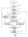
- step 30 After switching on the device 10, this first performs a self-test in step 30 to check the proper function. As part of the self-test, among other things, the individual components of the evaluation unit 14 and the image recording units 16, 18 checked for proper function. According to step 32, the outputs of the switching device 24 are then turned off, i. A monitored machine is reliably brought to a defined, safe state.
- step 34 which is optional, a light source is turned on as auxiliary lighting. This happens in particular if the existing ambient brightness is not sufficient for carrying out the subsequent image evaluation.
- the monitored danger area is picked up by the image acquisition units 16, 18.
- the image pickup unit 16 supplies a first image and the image pickup unit 18 a second image of the danger area. According to the exemplary embodiment shown here, this takes place in parallel, ie with synchronized image recording units 16, 18.
- step 42 a so-called image pre-processing then takes place.
- known methods for processing the recorded images are carried out here, for example an FPN correction (Fixed Pattern Noise).
- FPN correction Fixed Pattern Noise
- the recorded first and second images are matched with respect to basic brightness, etc.
- the image pair consisting of the first and the second image is subsequently evaluated with the aid of two different scene analysis methods in order to detect foreign objects within the danger zone.
- the first and second images of the danger area are subjected to correlation-based image analysis.
- a contour-based image analysis is performed.
- the contour-based image analysis involves region segmentation, i. the division of the first and second image into individual areas to be compared. Preferably, then only areas are evaluated that differ significantly from a reference image.
- an algorithm may be used, as it is for example in the EP 1 061 487 A1 or in Matusik et al., Image-Based Visual Hulls, SIGGRAPH 2000.
- an algorithm is preferably used, as described in the above-cited articles by U. Franke. In principle, however, other scene analysis methods come into consideration here.
- step 48 based on the results from the two scene analyzes, it is decided whether there is a guard room violation, i. whether an object has illegally penetrated into the monitored danger area. If this is not the case, according to step 50, the outputs of the switching device 24 are turned on, i. The monitored machine is put into operation.
- step 32 If a protection space violation has been detected by a foreign object, the method branches to step 32, whereafter the outputs of the switching device are switched off (or remain if a foreign object was already detected in the previous process run). The monitored machine etc. is thereby kept in its safe rest position. It is understood that the steps 34 to 50 are recursively repeated in order to ensure continuous protection of the danger zone during operation of the device 10.
- a preferred application of the new device 10 is shown in a plan view, while in the lower part of the associated side view is shown.
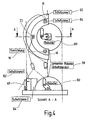
- the device 10 serves here to protect the danger area 58, which is provided by an automated robot 60 emanates.
- the danger area 58 lies here within a hemispherical enveloping surface around the robot 60 and corresponds to its movement or working area.
- the camera module 12, which contains the two image recording units 16, 18 in a common housing, is arranged above the danger zone and aligned therewith.
- the reference numerals 62 and 64 designate two staggered protection zones, the protection zone 62 forming a kind of warning zone, while the protection zone 64 forms a true prohibition zone. If a foreign object 66 enters the protection zone 62, this is detected by the device 10 on the basis of the scene analysis methods 44, 46. In one embodiment, the evaluation unit 14 then switches the robot 60 into a reduced-speed operation. Only when the protection zone 64 is breached is the emergency stop of the robot 60.
- the robot 60 if the protection zone 62 is breached, the robot 60 is moved to a safe rest position, from where the robot 60 can restart, as soon as the device 10 recognizes that the protection zone 62 is no longer damaged. If, however, the protection zone 64 is violated, a manual restart is required.
- the danger area 58 and the protection zones 62, 64 are each shown here with circular segment-shaped envelopes. However, in a preferred embodiment, the danger area 58 and the protection zones 62, 64 are adaptively adapted to the movements and working conditions of the robot 60.
- the two scene analysis methods 44, 46 include additional algorithms, with the aid of which parameters of the foreign object 66, for example, its shape, its direction of movement and speed, can be identified and tracked.
- the protection zones 62, 64 are adaptively defined around the robot 60 such that a close coexistence with the robot 60 is possible without jeopardizing the foreign object 66.
- FIG. 4 shows a modification of the application of FIG. 3.
- three image recording units 16, 18, 22 are arranged at a distance from each other above the robot 60 and its protective zones 62, 64.
- the image pickup units 16, 18, 22 have extremely wide-angle lenses, so that they can completely cover the protection zones 62, 64, even if they are arranged only at a small height above them.
- the image acquisition units 16, 18, 22 can be catadioptric cameras, that is to say cameras which use curved mirrors as imaging elements and have an annular field of view around a blind spot lying in the extension of their optical axis. If these cameras are aligned with the optical axis on the robot 60, they can not detect the robot itself, but their field of view overlaps well with the annular protection zones 62, 64 around the danger area 58. Thus, since the catadioptric cameras can detect any foreign object on its way into the danger area 58, it is not disadvantageous that the danger area 58 itself largely coincides with its blind spots overlaps. For monitoring, this may mean a simplification, since the evaluation unit 14, if it does not perceive the robot, nor its movements must distinguish from any movements of a foreign object to recognize the latter.
- the three cameras 16, 18, 22 are arranged so that each of the connecting line between two cameras in the field of view of the third.
- the position of a foreign object on such a connecting line is therefore always detectable on the basis of images supplied by the third camera and one of the two cameras lying on the connecting line.
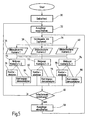
- a third image pickup step 40 takes place through the camera 3.
- steps 70, 72 from the images taken by cameras 1 and 2 or cameras 2 and 3.
- step 74 a third picture pair from the pictures of the cameras 3 and 1 are put together.
- Two different scene analysis methods are applied to the thus obtained at least two image pairs.
- a higher degree of recognition certainty is achieved if both analysis methods are performed on both image pairs (steps 80, 82), and if the step 74 has been performed, also its image pair is subjected to a contour analysis 84 and a correspondence analysis 86.
- step 48 it is decided on the basis of the results of the previous two, four or six scene analyzes, whether there is a trauma room violation. If this is the case, the outputs of the switching device 24 are turned off, otherwise they are turned on in step 50, that is, the monitored machine is put into operation, or if the machine in question is already in operation, the outputs remain switched on.
- contour analysis and the correspondence analysis can be replaced by any other scene analysis methods, or that more than two different scene analysis methods can be performed on a single image pair in order to further improve the detection security of a trauma injury.
- methods of scene analysis can be used which do not divide the images of the scene into image pairs, but instead determine a three-dimensional description of the scene by minimizing from an objective function to be determined simultaneously from all the images.
- Such algorithms are described, for example, in the post-published patent application DE 102 59 698-53 or in the above cited publication by Matusik et. al. described. To increase the reliability of detection and to achieve a diverse system, it is preferable to apply these two algorithms to all images in common.
Abstract
Description
Die vorliegende Erfindung betrifft ein Verfahren zum Absichern eines Gefahrenbereichs, insbesondere des Gefahrenbereichs einer automatisiert arbeitenden Maschine, bei dem mit zumindest einer ersten und einer zweiten Bildaufnahmeeinheit zumindest zwei Bilder des Gefahrenbereichs aufgenommen werden, wobei die Bildaufnahmeeinheiten versetzt zueinander angeordnet sind, und bei dem anhand einer Szenenanalyse der Bilder Fremdobjekte in dem Gefahrenbereich detektiert werden.The present invention relates to a method for securing a danger zone, in particular the danger zone of an automatically operating machine, in which at least two images of the danger zone are recorded with at least one first and one second image recording unit, wherein the image recording units are arranged offset from one another and in which Scene analysis of images Foreign objects are detected in the danger area.
Die Erfindung betrifft ferner eine Vorrichtung zum Absichern eines Gefahrenbereichs, insbesondere des Gefahrenbereichs einer automatisiert arbeitenden Maschine, mit zumindest einer ersten und einer zweiten Bildaufnahmeeinheit zum Aufnehmen von zumindest zwei Bildern des Gefahrenbereichs, wobei die Bildaufnahmeeinheiten versetzt zueinander angeordnet sind, und mit einer Auswerteeinheit, die anhand einer Szenenanalyse dieser Bilder Fremdobjekte in dem Gefahrenbereich detektiert.The invention further relates to a device for securing a danger zone, in particular the danger zone of an automatically operating machine, with at least a first one and a second image pickup unit for picking up at least two images of the danger area, the image pickup units being offset from each other, and an evaluation unit that detects foreign objects in the danger area based on a scene analysis of those images.
Ein Verfahren und eine Vorrichtung der genannten Art sind beispielsweise aus der DE 197 09 799 A1 bekannt.A method and a device of the type mentioned are known for example from DE 197 09 799 A1.
Zum Absichern von Gefahrenbereichen, insbesondere Gefahrenbereichen von Maschinen und industriellen Anlagen, werden bislang überwiegend Lichtschranken, Lichtgitter oder Laserscanner verwendet, häufig auch in Kombination mit mechanischen Absperrungen. Derartige Schutzmaßnahmen erfordern jedoch in der Regel eine recht aufwändige Installation und Justierung. Zudem sind diese Schutzmaßnahmen wenig flexibel, wenn es darum geht, die Absicherung des Gefahrenbereichs an unterschiedliche Betriebssituationen anzupassen.To protect hazardous areas, especially hazardous areas of machinery and industrial plants, so far mainly photoelectric barriers, light curtains or laser scanners are used, often in combination with mechanical barriers. However, such protective measures usually require a rather complex installation and adjustment. Moreover, these protective measures are not very flexible when it comes to adapting the protection of the danger zone to different operating situations.
Um diese Nachteile zu vermeiden, gibt es seit einiger zeit Bestrebungen, die Absicherung eines Gefahrenbereichs mit Hilfe einer Bildaufnahmeeinheit, in der Regel einer digitalen Kamera, sowie intelligenten Bildauswerteverfahren durchzuführen. Beispielhaft sei hierzu auf die DE 199 38 639 A1 verwiesen. In dieser Druckschrift ist eine Vorrichtung zur Absicherung eines Gefahrenbereichs beschrieben, bei der mit Hilfe der Bildaufnahmeeinheit und einem künstlichen, "kooperativen" Ziel eine virtuelle Barriere vor dem Gefahrenbereich erzeugt wird. Ein Durchbrechen der Barriere kann mit der Bildaufnahmeeinheit, ähnlich wie bei einer Lichtschranke, erkannt werden. Gegebenenfalls wird die Maschine, von der die Gefahr ausgeht, daraufhin abgeschaltet oder anderweitig in einen gefahrlosen Zustand versetzt.In order to avoid these disadvantages, efforts have been made for some time to secure a danger zone with the aid of an image recording unit, generally a digital camera, as well as intelligent image evaluation methods. For example, reference is made to DE 199 38 639 A1. This document describes a device for securing a danger zone, in which a virtual barrier is created in front of the danger zone with the aid of the image recording unit and an artificial, "cooperative" target. Breakthrough of the barrier can be detected with the image acquisition unit, similar to a light barrier. If necessary, the machine, from which the danger emanates, thereupon switched off or otherwise put into a safe state.
Wenngleich diese bekannte Vorrichtung bereits wesentliche Erleichterungen bei der Installation sowie eine höhere Flexibilität als herkömmliche Lichtschranken etc. besitzt, ist es weiterhin von Nachteil, dass mit dem "kooperativen Ziel" Installationsmaßnahmen im Bereich der abzusichernden Maschine erforderlich sind.Although this known device already has considerable ease of installation and a higher flexibility than conventional light barriers, etc., it is also disadvantageous that with the "cooperative goal" installation measures in the area of the machine to be protected are required.
Aus der eingangs genannten DE 197 09 799 A1 ist eine Vorrichtung mit zwei im Abstand voneinander angeordneten Bildaufnahmeeinheiten bekannt. Die von den beiden Bildaufnahmeeinheiten an eine Auswerteeinheit gelieferten Bilder werden einer Stereobildanalyse unterzogen, um ein dreidimensionales Abbild des Gefahrenbereichs zu erhalten. Das dreidimensionale Abbild wird anschließend mit einem dreidimensionalen Referenzmodell verglichen, um Fremdobjekte, d.h. sich unzulässigerweise in dem Gefahrenbereich befindliche Objekte, zu detektieren. Bei praktischen Versuchen mit einer vergleichbaren Anordnung hat sich jedoch gezeigt, dass die Erkennungssicherheit, mit der Fremdobjekte in dem Gefahrenbereich detektiert werden können, nicht ausreichend ist. Dies gilt zumindest so weit, wie eine entsprechende Vorrichtung zur Absicherung des Gefahrenbereichs von automatisiert arbeitenden Maschinen und dergleichen in industriellen Bereichen, d.h. zum Schutz von Personen, eingesetzt werden soll. Für eine solche Anwendung sind extrem kurze Reaktionszeiten (im Bereich von 30 ms) und eine praktisch einhundertprozentige Erkennungssicherheit erforderlich.From the aforementioned DE 197 09 799 A1 discloses a device with two spaced-apart image recording units is known. The images supplied by the two image recording units to an evaluation unit are subjected to stereo image analysis in order to obtain a three-dimensional image of the danger zone. The three-dimensional image is then compared with a three-dimensional reference model in order to detect foreign objects, ie objects located in the danger zone unduly. In practical experiments with a comparable arrangement, however, it has been found that the detection reliability with which foreign objects can be detected in the danger zone is not sufficient. This applies at least as far as a corresponding device for securing the danger zone of automated machines and the like in industrial areas, ie for the protection of persons should be used. Such an application requires extremely short reaction times (in the range of 30 ms) and virtually 100% detection reliability.
Eine vergleichbare Vorrichtung und ein entsprechendes Verfahren sind ferner aus der EP 1 061 487 A1 bekannt, wobei hinsichtlich der Nachteile das bereits Gesagte gilt.A comparable device and a corresponding method are also known from
Aus der DE 198 09 210 A1 sind eine Vorrichtung und ein Verfahren zum Überwachen einer sogenannten Szene bekannt. Die Szene wird mit einer einzelnen Bildaufnahmeeinheit aufgenommen und mit einem Referenzbild verglichen. Einzelne Punkte innerhalb der Szene werden mit Hilfe einer Lichtquelle gezielt beleuchtet, um bei der Bildaufnahme eine Markierung oder Individualisierung zu erhalten. Dieses Verfahren besitzt jedoch den Nachteil, dass durch die Beleuchtung der Szene, im konkreten Anwendungsfall also des Gefahrenbereichs, eine Störanfälligkeit durch Fremdlichteinstreuung gegeben ist. Störungen durch Fremdlicht können insbesondere in industriellen Produktionsumgebungen auftreten, beispielsweise bei Schweißrobotern oder bei großen Abkantpressen.From DE 198 09 210 A1 an apparatus and a method for monitoring a so-called scene are known. The scene is taken with a single image capture unit and compared to a reference image. Individual points within the scene are specifically illuminated with the aid of a light source in order to obtain a marking or individualization during the image recording. However, this method has the disadvantage that by the illumination of the scene, in the specific application, ie the danger area, a susceptibility is given by Fremdlichteinstreuung. Interference from extraneous light can occur especially in industrial production environments, for example in welding robots or large press brakes.
Vor diesem Hintergrund ist es eine Aufgabe der vorliegenden Erfindung, ein alternatives Verfahren und eine entsprechende Vorrichtung anzugeben, mit denen insbesondere der Gefahrenbereich einer automatisiert arbeitenden Maschine ohne großen Installationsaufwand, jedoch mit hinreichender Zuverlässigkeit abgesichert werden kann.Against this background, it is an object of the present invention to provide an alternative method and a corresponding device with which, in particular, the danger zone of an automated machine can be secured without great installation effort, but with sufficient reliability.
Diese Aufgabe wird mit einem Verfahren der eingangs genannten Art gelöst, bei dem die Szenenanalyse anhand der mindestes zwei Bilder unter Anwendung mindestens zweier algorithmisch unterschiedlicher Verfahren durchgeführt wird und dass der Gefahrenbereich abgesichert wird, wenn zumindest eines der Analyseverfahren eine Fremdobjektdetektion liefert.This object is achieved by a method of the type mentioned above, in which the scene analysis is performed on the basis of the at least two images using at least two algorithmically different methods and that the danger area is hedged if at least one of the analysis methods provides a foreign object detection.
Die Aufgabe wird des Weiteren durch eine Vorrichtung der eingangs genannten Art gelöst, bei der die Auswerteeinheit so ausgebildet ist, dass die Szenenanalyse unter Anwendung mindestens zweier algorithmisch unterschiedlicher Verfahren durchgeführt wird, und bei der ferner ein Schaltmittel implementiert ist, das aktiviert wird, wenn zumindest eines der Szenenanalyseverfahren eine Fremdobjektdetektion liefert.The object is further achieved by a device of the aforementioned type, in which the evaluation unit is designed so that the scene analysis is performed using at least two algorithmically different methods, and in which further a switching means is implemented, which is activated if at least one of the scene analysis methods provides a foreign object detection.
Die erfindungsgemäße Lösung basiert damit im Kern auf der dreidimensionalen Auswertung von mindestens zwei Bildern, die mit zueinander versetzten Bildaufnahmeeinheiten von dem Gefahrenbereich aufgenommen werden. Entsprechende Szenenanalyseverfahren sind im Stand der Technik für sich genommen bekannt. Beispielsweise sei auf das Buch "Three-Dimensional Computer Vision: A Geometric Viewpoint", von Olivier Faugeras, MIT-Press, Cambridge oder auf den Artikel "Fast Stereo Based Object Detection for Stop & Go Traffic", von U. Franke/I. Kutzbach, INTELLIGENT VEHICLES SYMPOSIUM, Seiten 339-344, Tokio, 1996 verwiesen. Ein entsprechendes Verfahren wird auch in der nachveröffentlichten Patentanmeldung DE 102 59 698-53 beschrieben. Die bislang bekannten Verfahren liefern für sich genommen jedoch nicht die erforderliche Erkennungssicherheit, um die Absicherung des Gefahrenbereichs einer automatisiert arbeitenden Maschine zuverlässig zu gewährleisten. Es hat sich nun jedoch überraschenderweise gezeigt, dass die Kombination verschiedener dreidimensionalen Szenenanalyseverfahren, die parallel nebeneinander ausgeführt werden, das Erreichen der für diesen Anwendungszweck erforderlichen Erkennungssicherheit ermöglicht.The solution according to the invention is thus based essentially on the three-dimensional evaluation of at least two images, which are recorded by mutually offset image recording units of the danger area. Corresponding scene analysis methods are known per se in the prior art. For example, the book "Three-Dimensional Computer Vision: A Geometric Viewpoint," by Olivier Faugeras, MIT-Press, Cambridge, or the article "Fast Stereo Based Object Detection for Stop & Go Traffic," by U. Franke / I. Kutzbach, INTELLIGENT VEHICLES SYMPOSIUM, pp. 339-344, Tokyo, 1996. A corresponding method is also described in the post-published patent application DE 102 59 698-53. The methods known hitherto, however, do not provide the required recognition reliability per se in order to reliably ensure the safeguarding of the danger zone of an automated machine. However, it has now surprisingly been found that the combination of different three-dimensional scene analysis methods, which are performed side by side in parallel, makes it possible to achieve the recognition reliability required for this application.
Mit Hilfe der getrennten Szenenanalyseverfahren werden Objekte in den beiden aufgenommenen Bildern detektiert, und es wird deren räumliche Position bestimmt. Anschließend wird anhand der räumlichen Position der Objekte überprüft, ob diese sich in dem überwachten Gefahrenbereich befinden und ob es sich dabei um "Fremdobjekte" handelt. Zusätzliche externe Hilfsmittel, wie beispielsweise ein kooperatives Ziel oder eine gezielte Markierung einzelner Punkte des aufgenommenen Gefahrenbereichs mit Licht, sind nicht erforderlich. Die erfindungsgemäße Lösung ermöglicht damit einen geringen Installationsaufwand. Des weiteren ermöglichen die neue Vorrichtung und das entsprechende Verfahren aufgrund der zahlreichen Varianten moderner Auswertesysteme eine große Flexibilität.With the aid of the separate scene analysis methods, objects in the two recorded images are detected, and it becomes determines their spatial position. Subsequently, it is checked on the basis of the spatial position of the objects, whether these are in the monitored danger area and whether these are "foreign objects". Additional external aids, such as a cooperative target or a targeted marking of individual points of the recorded danger area with light, are not required. The solution according to the invention thus allows a low installation cost. Furthermore, the new device and the corresponding method allow great flexibility due to the numerous variants of modern evaluation systems.
Die verschiedenen Szenenanalyseverfahren, die heute bereits zur Verfügung stehen, besitzen jeweils individuelle Stärken und Schwächen, insbesondere im Hinblick auf die Erkennungssicherheit und Störanfälligkeit. Durch Kombination verschiedener Verfahren lassen sich die jeweiligen Schwächen kompensieren. Sobald auch nur eines der Szenenanalyseverfahren eine Fremdobjektdetektion liefert, wird der Gefahrenbereich abgesichert, beispielsweise also die überwachte Maschine abgeschaltet oder anderweitig in Ruhezustand versetzt. Die an sich hohen Anforderungen, die an Schutzeinrichtungen für die Maschinensicherheit gestellt werden, lassen sich so überraschend einfach erreichen.The various scene analysis methods that are already available today each have individual strengths and weaknesses, in particular with regard to detection reliability and susceptibility to interference. By combining different methods, the respective weaknesses can be compensated. As soon as only one of the scene analysis methods delivers a foreign object detection, the danger area is protected, for example, the monitored machine is switched off or otherwise put into a resting state. The intrinsically high demands placed on guards for machine safety can be achieved in a surprisingly simple manner.
Darüber hinaus besitzt die neue Vorrichtung den Vorteil, dass durch die Verwendung unterschiedlicher Verfahren zur Szenenanalyse zwangsläufig eine Diversität geschaffen wird. Damit ist die Eigenfehlersicherheit der Gesamtvorrichtung gegenüber Funktionsausfällen und Störungen reduziert. Dies ist vor allem im Hinblick auf den bevorzugten Anwendungsbereich, nämlich zur Absicherung von Maschinen und Anlagen, von großer Bedeutung.In addition, the new device has the advantage that diversity is inevitably created by using different method of scene analysis. Thus, the intrinsic error safety of the overall device against functional failures and interference is reduced. This is particularly important in view of the preferred field of application, namely for the protection of machinery and equipment, of great importance.
Die genannte Aufgabe ist daher vollständig gelöst.The stated task is therefore completely solved.
Unter Stereobildverarbeitung wird hier verstanden, dass zwei Kameras mit annähernd parallelen optischen Achsen und annähernd identischer Brennweite verwendet werden. Es wird herbei eine Disparitätskarte (3-D-Punktewolke) bestimmt, indem ein Pixel im linken Bild einem Pixel im rechten Bild zugeordnet wird, dies im allgemeinen basierend auf einer kleinen lokalen Umgebung der jeweiligen Pixel.Under stereo image processing is understood here that two cameras are used with approximately parallel optical axes and approximately identical focal length. A disparity map (3-D point cloud) is determined by assigning a pixel in the left image to a pixel in the right image, generally based on a small local environment of the respective pixels.
Demgegenüber versteht man unter einer dreidimensionalen Szenenanalyse ein Verfahren, bei welchem Objektparameter so adaptiert werden, dass eine Optimierung der Parameter anhand einer Zielfunktion erfolgt, die simultan anhand mindestens zweier Bilder des Objekts ermittelt wird (beispielsweise: Matusik et al., "Image-Based Visual Hulls", SIGGRAPH 2000 oder die nachveröffentlichte Patentanmeldung DE 102 59 698-53). Die Erkennungssicherheit wird gegenüber üblichen Stereobildverarbeitungsverfahren gesteigert, da hier die Erkennung auf einer Ebene mit höherem Informationsgehalt erfolgt.By contrast, a three-dimensional scene analysis is understood as a method in which object parameters are adapted such that the parameters are optimized on the basis of a target function which is determined simultaneously using at least two images of the object (for example: Matusik et al., Image-Based Visual Hulls ", SIGGRAPH 2000 or the post-published patent application DE 102 59 698-53). The detection reliability is increased compared to conventional stereo image processing methods, since the detection takes place on a level with a higher information content.
In einer Ausgestaltung der Erfindung werden das erste und das zweite Bild einerseits einer korrelationsbasierten Szenenanalyse und andererseits einer konturbasierten Szenenanalyse unterzogen.In one embodiment of the invention, the first and the second image are subjected on the one hand to a correlation-based scene analysis and on the other hand to a contour-based scene analysis.
Eine korrelationsbasierte Szenenanalyse im Sinne der Erfindung ist beispielsweise aus dem bereits erwähnten Artikel von Franke/Kutzbach oder einem weiteren Artikel mit dem Titel "Real-Time Stereo Vision for Urban Traffic Scene Understanding" von U. Franke/A. Joos, IEEE INTELLIGENT VEHICLES SYMPOSIUM, 2000 bekannt.A correlation-based scene analysis within the meaning of the invention is, for example, from the aforementioned article by Franke / Kutzbach or another article entitled "Real-Time Stereo Vision for Urban Traffic Scene Understanding" by U. Franke / A. Joos, IEEE INTELLIGENT VEHICLES SYMPOSIUM, 2000 known.
Eine konturbasierte Szenenanalyse ist beispielsweise aus der Veröffentlichung von Matusik oder der bereits erwähnten nachveröffentlichten Patentanmeldung DE 102 59 698-53 bekannt. Wie sich bei praktischen Versuchen gezeigt hat, liefert die Kombination der genannten Verfahren zur Szenenanalyse besonders gute Ergebnisse im Hinblick auf die Erkennungssicherheit und ferner auch im Hinblick auf die Eigenfehlersicherheit der Gesamtvorrichtung.A contour-based scene analysis is known, for example, from the publication of Matusik or the previously mentioned post-published patent application DE 102 59 698-53. As has been shown in practical experiments, the combination of the mentioned methods for scene analysis provides particularly good results in terms of detection reliability and also with regard to the intrinsic error safety of the overall device.
In einer weiteren Ausgestaltung der Erfindung werden bei zumindest einem der Szenenanalyseverfahren nur solche Bereiche in Bildern bearbeitet, die sich signifikant von einem Referenzbild unterscheiden.In a further embodiment of the invention, in at least one of the scene analysis methods, only those areas in images which differ significantly from a reference image are processed in images.
Diese Maßnahme hat sich für den bevorzugten Anwendungsbereich der Erfindung als besonders vorteilhaft erwiesen, da hierdurch die Verarbeitungsgeschwindigkeit gesteigert werden kann. Dementsprechend lassen sich die Reaktionszeiten der Vorrichtung verkürzen, was einerseits eine größere Flexibilität bei der Gestaltung von Schutzzonen und andererseits einen besseren Schutz von Bedienpersonal ermöglicht.This measure has proved to be particularly advantageous for the preferred field of application of the invention, as this can increase the processing speed. Accordingly, the reaction times of the device can be shortened, which on the one hand allows greater flexibility in the design of protection zones and on the other hand better protection of operating personnel.
Bei einer einfachen Ausgestaltung des Verfahrens wird lediglich ein Bildpaar erzeugt, an welchem die zwei Szenenanalyseverfahren durchgeführt werden. Diese Ausgestaltung hat den Vorteil, dass sie apparativ einfach realisierbar ist. Unter ungünstigen Bedingungen kann sich jedoch als nachteilig auswirken, dass für Strukturen im Bild, die entlang der Verbindungslinie der zwei Bildaufnahmeeinheiten ausgerichtet sind, eine dreidimensionale Analyse nicht möglich ist.In a simple embodiment of the method, only one image pair is generated, on which the two scene analysis methods are performed. This embodiment has the advantage that it is easy to implement in terms of apparatus. However, under unfavorable conditions, this can have a detrimental effect on structures in the image that run along the connecting line of the two Image acquisition units are aligned, a three-dimensional analysis is not possible.
Um auch solche Strukturen dreidimensional erfassen zu können, ist es von Vorteil, mit mindestens einer weiteren Bildaufnahmeeinheit mindestens ein weiteres Bild der Szene aufzunehmen. Diese weiteren Bildaufnahmeeinheiten sollen dabei nicht auf einer Linie mit den ersten beiden Bildaufnahmeeinheiten liegen.In order to be able to detect such structures three-dimensionally, it is advantageous to record at least one further image of the scene with at least one further image recording unit. These further image recording units should not be in line with the first two image recording units.
Um die Vorrichtung apparativ einfach zu halten, ist es von Vorteil, wenn drei aufgenommene Bilder der Szene als zwei Bildpaare aufgefasst werden, wobei das erste und das zweite Bildpaar jeweils ein Bild gemeinsam haben. Dieses Vorgehen lässt sich entsprechend auch auf die Verwendung von mehr als drei Bildern ausdehnen.In order to keep the apparatus simple in terms of apparatus, it is advantageous if three recorded images of the scene are understood as two image pairs, the first and the second image pair each having one image in common. This procedure can be extended accordingly to the use of more than three images.
Ein besonders hohes Maß an Sicherheit wird erreicht, wenn auf jedes Bildpaar mehrere Szenenanalyseverfahren angewendet werden.A particularly high level of security is achieved if several scene analysis methods are applied to each image pair.
In einer besonders vorteilhaften Ausgestaltung verfügt die erfindungsgemäße Vorrichtung über wenigstens eine dritte Bildaufnahmeeinheit zum Aufnehmen eines dritten Bildes des Gefahrenbereichs. Hierbei ist die Auswerteeinheit so eingerichtet, dass wenigstens eines der zwei Szenenanalyseverfahren auf die wenigstens drei Bilder angewandt wird. Durch die Auswahl eines einzigen der zwei möglichen Verfahren zur Szenenanalyse wird die notwendige Rechenleistung und Rechenzeit gesenkt.In a particularly advantageous embodiment, the device according to the invention has at least one third image recording unit for recording a third image of the danger zone. In this case, the evaluation unit is set up such that at least one of the two scene analysis methods is applied to the at least three images. By selecting a single one of the two possible scene analysis techniques, the necessary computational power and computation time are reduced.
In einer weiteren Ausgestaltung werden mehrere zeitlich aufeinanderfolgende Gruppen von mindestens zwei synchron aufgenommenen Bildern ausgewertet, um zumindest einen Bewegungsparameter eines detektierten Fremdobjektes zu bestimmen, insbesondere Geschwindigkeit, Bewegungsrichtung etc.In a further embodiment, a plurality of temporally successive groups of at least two synchronously recorded Evaluated images to determine at least one motion parameter of a detected foreign object, in particular speed, direction of movement, etc.
Durch diese Maßnahme lässt sich der Gefährdungsgrad, der von der überwachten Maschine oder dergleichen ausgeht, genauer einschätzen. Infolgedessen ist eine intelligentere Reaktion auf ein erkanntes Fremdobjekt möglich. Beispielsweise kann bei einem sich nur langsam bewegenden Fremdobjekt innerhalb des Gefahrenbereichs zunächst eine Vorwarnung erzeugt werden, während bei einem sich schnell bewegenden Fremdobjekt die überwachte Maschine unmittelbar abgeschaltet wird.By this measure, the degree of danger emanating from the monitored machine or the like, can be estimated more accurately. As a result, a smarter response to a detected foreign object is possible. For example, in the case of a foreign object moving only slowly, an advance warning can be generated within the danger zone, while in the case of a rapidly moving foreign object, the monitored machine is switched off immediately.
In einer weiteren Ausgestaltung wird eine zukünftige Belichtungszeit der Bildaufnahmeeinheiten in Abhängigkeit von den aktuellen Bildern eingestellt.In a further embodiment, a future exposure time of the image recording units is set as a function of the current images.
Durch diese Maßnahme wird die Belichtungszeit der Bildaufnahmeeinheiten adaptiv an wechselnde Umgebungsbedingungen angepasst. Die neue Vorrichtung kann damit automatisch auf veränderte Umgebungsbedingungen, beispielsweise Tageslichteinflüsse, reagieren. Einerseits wird dadurch die Erkennungssicherheit gesteigert, andererseits lassen sich unerwünschte Fehlalarme besser vermeiden.As a result of this measure, the exposure time of the image recording units is adaptively adapted to changing environmental conditions. The new device can thus automatically respond to changing environmental conditions, such as daylight influences. On the one hand, this increases detection reliability, on the other hand, unwanted false alarms can be better avoided.
In einer weiteren Ausgestaltung der Erfindung sind wenigstens zwei der Bildaufnahmeeinheiten in einem gemeinsamen Gerätegehäuse angeordnet.In a further embodiment of the invention, at least two of the image recording units are arranged in a common device housing.
Diese Ausgestaltung besitzt den Vorteil, dass ein Großteil der erforderlichen Kalibrierungsarbeiten sowie die relative Justierung der beiden Bildaufnahmeeinheiten zueinander herstellerseitig im Werk vorgenommen werden können. Der Installationsaufwand der erfindungsgemäßen Vorrichtung vor Ort wird dadurch noch weiter vereinfacht. Außerdem wird durch eine präzise Kalibrierung unter Laborbedingungen die Erkennungssicherheit der Gesamtvorrichtung weiter gesteigert.This embodiment has the advantage that much of the required calibration work as well as the relative adjustment the two image recording units can be made to each other manufacturer in the factory. The installation cost of the device according to the invention on site is thereby further simplified. In addition, the accuracy of detection of the overall device is further enhanced by precise calibration under laboratory conditions.
Es versteht sich, dass die vorstehend genannten und die nachstehend noch zu erläuternden Merkmale nicht nur in der jeweils angegebenen Kombination, sondern auch in anderen Kombinationen oder in Alleinstellung verwendbar sind, ohne den Rahmen der vorliegenden Erfindung zu verlassen.It is understood that the features mentioned above and those yet to be explained below can be used not only in the particular combination given, but also in other combinations or in isolation, without departing from the scope of the present invention.
Ausführungsbeispiele der Erfindung sind in der Zeichnung dargestellt und werden in der nachfolgenden Beschreibung näher erläutert. Es zeigen:
- Fig. 1
- ein vereinfachtes Blockschaltbild einer erfindungsgemäßen Vorrichtung;
- Fig. 2
- ein vereinfachtes Flussdiagramm zur Erläuterung des erfindungsgemäßen Verfahrens;
- Fig. 3
- eine Skizze zur Erläuterung einer bevorzugten Anwendung der erfindungsgemäßen Vorrichtung;
- Fig. 4
- eine Abwandlung der in Fig. 3 gezeigten Anwendung; und
- Fig. 5
- ein an die Abwandlung der Fig. angepasstes Flussdiagramm des erfindungsgemäßen Verfahrens.
- Fig. 1
- a simplified block diagram of a device according to the invention;
- Fig. 2
- a simplified flowchart for explaining the method according to the invention;
- Fig. 3
- a sketch for explaining a preferred application of the device according to the invention;
- Fig. 4
- a modification of the application shown in Figure 3; and
- Fig. 5
- a adapted to the modification of Fig. Flowchart of the inventive method.
In Fig.1 ist eine erfindungsgemäße Vorrichtung in ihrer Gesamtheit mit der Bezugsziffer 10 bezeichnet.In Fig.1 a device according to the invention is designated in its entirety by the
Die Vorrichtung 10 beinhaltet im Wesentlichen ein Kameramodul 12 und eine Auswerteeinheit 14. Innerhalb des Kameramoduls 12 sind zwei Bildaufnahmeeinheiten 16, 18 dargestellt (dort als "Kamera 1" und "Kamera 2" bezeichnet). Die Bildaufnahmeeinheiten 16, 18 können komplette, eigenständig funktionsfähige Kameras sein. Alternativ hierzu können einzelne Teile der beiden Kameras jedoch auch gemeinsam genutzt sein, so dass es sich dann im Wesentlichen um zwei getrennte Bildsensoren, gegebenenfalls mit jeweils zugehöriger Optik, handelt.The
Die Bildaufnahmeeinheiten 16, 18 sind über einen Bus 20 mit der räumlich etwas abgesetzten Auswerteeinheit 14 verbunden. Alternativ hierzu ist es auch möglich, die beiden Bildaufnahmeeinheiten 16, 18 und die Auswerteeinheit 14 in einem gemeinsamen Gehäuse zu integrieren oder eine sonstige analoge oder digitale Schnittstelle zu verwenden. Die vorliegend dargestellte Anordnung mit einer räumlich getrennten Auswerteeinheit 14 besitzt die Vorteile eines modularen Systems, wie geringeres Gewicht der Einzelkomponenten, separate Austauschbarkeit etc. Außerdem kann auf diese Weise sehr einfach ein weiteres Kameramodul 22, hier nur schematisch dargestellt, an die gleiche Auswerteeinheit 14 angeschlossen werden.The
Mit der Bezugsziffer 24 ist eine Schaltvorrichtung bezeichnet, die beispielsweise Relais oder Schütze beinhaltet. Mit der Schaltvorrichtung können die Antriebe einer überwachten Maschine, Anlage und dergleichen in an sich bekannter Weise abgeschaltet werden. Die Schaltvorrichtung 24 kann beispielsweise auch in Form einer fehlersicheren SPS (Speicher Programmierbaren Steuerung), d.h. einer sogenannten Sicherheitssteuerung, realisiert sein. In diesem Fall ist es bevorzugt, wenn die Auswerteeinheit 14 über einen sicheren Feldbus, beispielsweise den sogenannten SafetyBus® der Pilz GmbH & Co., Deutschland, mit der Sicherheitssteuerung verbunden ist. Bei der Sicherheitssteuerung handelt es sich beispielsweise um eine PSS 3000 der Firma Pilz GmbH & Co.
Die grundsätzliche Funktionsweise der Vorrichtung 10 sowie ein bevorzugtes Anwendungsbeispiel werden nachfolgend anhand der Fig. 2 und 3 beschrieben. Gleiche Bezugszeichen bezeichnen dabei jeweils gleiche Elemente.The basic operation of the
Nach dem Einschalten der Vorrichtung 10 führt diese gemäß Schritt 30 zunächst einen Selbsttest durch, um die einwandfreie Funktion zu überprüfen. Im Rahmen des Selbsttests werden unter anderem die einzelnen Komponenten der Auswerteeinheit 14 sowie der Bildaufnahmeeinheiten 16, 18 auf einwandfreie Funktion hin überprüft. Gemäß Schritt 32 werden dann die Ausgänge der Schaltvorrichtung 24 ausgeschaltet, d.h. eine überwachte Maschine wird zuverlässig in einen definierten, sicheren Zustand gebracht.After switching on the
Gemäß Schritt 34, der optional ist, wird eine Lichtquelle als Zusatzbeleuchtung eingeschaltet. Dies geschieht insbesondere dann, wenn die vorhandene Umgebungshelligkeit für die Durchführung der nachfolgenden Bildauswertung nicht ausreichend ist.In
Gemäß den Schritten 36, 38 wird der überwachte Gefahrenbereich von den Bildaufnahmeeinheiten 16, 18 aufgenommen. Anders ausgedrückt liefert die Bildaufnahmeeinheit 16 ein erstes und die Bildaufnahmeeinheit 18 ein zweites Bild des Gefahrenbereichs. Gemäß dem hier dargestellten Ausführungsbeispiel erfolgt dies parallel, d.h. mit zueinander synchronisierten Bildaufnahmeeinheiten 16, 18.According to
Nach Schritt 42 erfolgt anschließend eine sogenannte Bildvorverarbeitung. Je nach Anwendungsfall werden hier an sich bekannte Verfahren zur Aufbereitung der aufgenommenen Bilder durchgeführt, beispielsweise eine FPN-Korrektur (Fixed Pattern Noise). Des Weiteren werden die aufgenommenen ersten und zweiten Bilder im Hinblick auf Grundhelligkeiten etc. aneinander angepasst.After
Gemäß den Schritten 44, 46 erfolgt anschließend die Auswertung des aus dem ersten und dem zweiten Bild bestehenden Bildpaars mit Hilfe von zwei verschiedenen Szenenanalyseverfahren, um Fremdobjekte innerhalb des Gefahrenbereichs zu detektieren. Im Schritt 44 werden das erste und zweite Bild des Gefahrenbereichs einer korrelationsbasierten Bildanalyse unterzogen. Im Schritt 46 erfolgt hingegen eine konturbasierte Bildanalyse.In accordance with
In einem besonders bevorzugten Ausführungsbeispiel beinhaltet die konturbasierte Bildanalyse eine Regionensegmentierung, d.h. die Einteilung des ersten und zweiten Bildes in einzelne zu vergleichende Bereiche. Bevorzugt werden dann nur Bereiche ausgewertet, die sich von einem Referenzbild signifikant unterscheiden.In a particularly preferred embodiment, the contour-based image analysis involves region segmentation, i. the division of the first and second image into individual areas to be compared. Preferably, then only areas are evaluated that differ significantly from a reference image.
Alternativ kann in anderen Ausführungsbeispielen jedoch auch ein Algorithmus verwendet werden, wie er beispielsweise in der EP 1 061 487 A1 oder in Matusik et al., "Image-Based Visual Hulls", SIGGRAPH 2000 beschrieben ist. Für die korrelationsbasierte Bildanalyse wird bevorzugt ein Algorithmus verwendet, wie er in den oben zitierten Artikeln von U. Franke beschrieben ist. Grundsätzlich kommen hier jedoch auch andere Szenenanalyseverfahren in Betracht.Alternatively, however, in other embodiments, an algorithm may be used, as it is for example in the
Im Schritt 48 wird anhand der Ergebnisse aus den beiden Szenenanalysen entschieden, ob eine Schutzraumverletzung vorliegt, d.h. ob ein Objekt unzulässigerweise in den überwachten Gefahrenbereich eingedrungen ist. Ist dies nicht der Fall, werden gemäß Schritt 50 die Ausgänge der Schaltvorrichtung 24 eingeschaltet, d.h. die überwachte Maschine wird in Betrieb genommen.In
Wurde eine Schutzraumverletzung durch ein Fremdobjekt detektiert, verzweigt das Verfahren zum Schritt 32, wonach die Ausgänge der Schaltvorrichtung ausgeschaltet werden (oder bleiben, wenn bereits im vorherigen Verfahrensdurchlauf ein Fremdobjekt detektiert wurde). Die überwachte Maschine etc. wird hierdurch in ihrer sicheren Ruheposition gehalten. Es versteht sich, dass die Schritte 34 bis 50 rekursiv wiederholt werden, um im Betrieb der Vorrichtung 10 eine kontinuierliche Absicherung des Gefahrenbereichs zu gewährleisten.If a protection space violation has been detected by a foreign object, the method branches to step 32, whereafter the outputs of the switching device are switched off (or remain if a foreign object was already detected in the previous process run). The monitored machine etc. is thereby kept in its safe rest position. It is understood that the
Im oberen Teil der Fig. 3 ist ein bevorzugter Anwendungsfall der neuen Vorrichtung 10 in einer Draufsicht dargestellt, während im unteren Teil die zugehörige Seitenansicht gezeigt ist.In the upper part of Fig. 3, a preferred application of the
Die Vorrichtung 10 dient hier zur Absicherung des Gefahrenbereichs 58, der von einem automatisiert arbeitenden Roboter 60 ausgeht. Der Gefahrenbereich 58 liegt hier innerhalb einer halbkugelförmigen Hüllfläche um den Roboter 60 und entspricht seinem Bewegungs- oder Arbeitsbereich. Das Kameramodul 12, das die zwei Bildaufnahmeeinheiten 16, 18 in einem gemeinsamen Gehäuse enthält, ist oberhalb des Gefahrenbereichs angeordnet und auf diesen ausgerichtet.The
Mit den Bezugsziffern 62 und 64 sind zwei gestaffelte Schutzzonen bezeichnet, wobei die Schutzzone 62 hier eine Art Warnzone bildet, während die Schutzzone 64 einen echten Verbotsbereich bildet. Tritt ein Fremdobjekt 66 in die Schutzzone 62 ein, wird dies von der Vorrichtung 10 aufgrund der Szenenanalyseverfahren 44, 46 detektiert. In einem Ausführungsbeispiel schaltet die Auswerteeinheit 14 den Roboter 60 dann in einen Betrieb mit reduzierter Geschwindigkeit. Erst bei Verletzung der Schutzzone 64 erfolgt ein Not-Aus des Roboters 60.The reference numerals 62 and 64 designate two staggered protection zones, the
In einem weiteren Ausführungsbeispiel wird bei Verletzung der Schutzzone 62 der Roboter 60 in eine sichere Ruheposition gefahren, von wo aus der Roboter 60 einen Neustart aufnehmen kann, sobald die Vorrichtung 10 erkennt, dass die Schutzzone 62 nicht mehr verletzt ist. Wird hingegen die Schutzzone 64 verletzt, ist ein Neustart von Hand erforderlich.In a further embodiment, if the
Der Gefahrenbereich 58 und die Schutzzonen 62, 64 sind hier jeweils mit kreisabschnittsförmigen Hüllkurven dargestellt. In einem bevorzugten Ausführungsbeispiel werden der Gefahrenbereich 58 und die Schutzzonen 62, 64 jedoch adaptiv an die Bewegungen und Arbeitszustände des Roboters 60 angepasst. Bevorzugt beinhalten die beiden Szenenanalyseverfahren 44, 46 dabei Zusatzalgorithmen, mit deren Hilfe Parameter des Fremdobjekts 66, beispielsweise seine Form, seine Bewegungsrichtung und -geschwindigkeit, identifiziert und verfolgt werden können. In Abhängigkeit davon werden die Schutzzonen 62, 64 adaptiv so um den Roboter 60 herum definiert, dass ohne Gefährdung des Fremdobjektes 66 ein "enges" Nebeneinander mit dem Roboter 60 möglich ist. Bei dieser Ausführung ist es beispielsweise möglich, mehrere Roboter 60 auf engem Raum nebeneinander anzuordnen, wobei mit Hilfe der Vorrichtung 10 Kollisionen untereinander verhindert werden. Ferner können in einem weiteren Ausführungsbeispiel Werkstücke (hier nicht dargestellt), die dem Roboter 60 zugeführt werden, von "unbefugten" Fremdobjekten unterschieden werden. Die Arbeitsweise des Roboters 60 kann auf diese Weise optimiert werden, während gleichzeitig die Sicherheit von beteiligtem Bedienpersonal gewährleistet ist.The
Fig. 4 zeigt eine Abwandlung des Anwendungsfalles aus Fig. 3. Anstelle eines einzelnen Kameramoduls wie im Falle der Fig. 3 sind hier drei Bildaufnahmeeinheiten 16, 18, 22 jeweils voneinander beabstandet oberhalb des Roboters 60 und seiner Schutzzonen 62, 64 angeordnet. Die Bildaufnahmeeinheiten 16, 18, 22 haben extrem weitwinklige Objektive, so dass sie die Schutzzonen 62, 64 vollständig erfassen können, selbst wenn sie nur in geringer Höhe über diesen angeordnet sind.FIG. 4 shows a modification of the application of FIG. 3. Instead of a single camera module as in the case of FIG. 3, three
Insbesondere kann es sich bei den Bildaufnahmeeinheiten 16, 18, 22 um katadioptrische Kameras handeln, das heißt um Kameras, die gewölbte Spiegel als bildgebende Elemente einsetzen und ein ringförmiges Blickfeld rings um einen in Verlängerung ihrer optischen Achse liegenden toten Winkel haben. Wenn diese Kameras mit ihrer optischen Achse auf den Roboter 60 ausgerichtet sind, können sie zwar den Roboter selbst nicht erfassen, doch überlappt ihr Blickfeld gut mit den ringförmigen Schutzzonen 62, 64 rings um den Gefahrenbereich 58. Da die katadioptrischen Kameras somit jedes Fremdobjekt auf seinem Weg in den Gefahrenbereich 58 erkennen können, ist es nicht nachteilig, dass der Gefahrenbereich 58 selbst sich weitgehend mit ihren toten Winkeln überschneidet. Für die Überwachung kann dies vielmehr eine Vereinfachung bedeuten, da die Auswerteeinheit 14, wenn sie den Roboter nicht wahrnimmt, auch nicht dessen Bewegungen von eventuellen Bewegungen eines Fremdobjektes unterscheiden muss, um Letzteres zu erkennen.In particular, the
Die drei Kameras 16, 18, 22 sind so angeordnet, dass jeweils die Verbindungslinie zwischen zwei Kameras im Blickfeld der dritten liegt. Die Position eines Fremdobjektes auf einer solchen Verbindungslinie ist daher stets erfassbar anhand von Bildern, die von der dritten Kamera und einer der zwei auf der Verbindungslinie liegenden Kameras geliefert werden.The three
Die Arbeitsweise der Vorrichtung aus Fig. 4 wird mit Bezug auf das Flussdiagramm der Fig. 5 beschrieben. Die Verfahrensschritte 30, 32, 34, 36, 38 sind identisch mit den bereits mit Bezug auf Fig. 2 beschriebenen und werden daher nicht erneut erläutert. Zusätzlich zu den zwei Bildaufnahmeschritten 36, 38 durch Kamera 1 und Kamera 2 findet ein dritter Bildaufnahmeschritt 40 durch die Kamera 3 statt. Es liegen somit drei gleichzeitig aus verschiedenen Blickwinkeln aufgenommene Bilder vor, die in unterschiedlicher Weise zu Bildpaaren kombiniert werden können. Es werden mindestens zwei unterschiedliche Bildpaare benötigt, die in den Schritten 70, 72 aus den von den Kameras 1 und 2 bzw. Kameras 2 und 3 aufgenommenen Bildern zusammengestellt werden. Fakultativ kann in Schritt 74 ein drittes Bildpaar aus den Bildern der Kameras 3 und 1 zusammengestellt werden.The operation of the apparatus of Fig. 4 will be described with reference to the flowchart of Fig. 5. The method steps 30, 32, 34, 36, 38 are identical to those already described with reference to FIG. 2 and are therefore not explained again. In addition to the two image pickup steps 36, 38 by
Auf die so erhaltenen wenigstens zwei Bildpaare werden zwei verschiedene Szenenanalyseverfahren angewendet. Im einfachsten Fall kann man sich zum Beispiel darauf beschränken, in Schritt 76 eine Konturanalyse am Bildpaar der Kameras 1 und 2 und in Schritt 78 eine Korrespondenzanalyse am Bildpaar der Kameras 2 und 3 durchzuführen. Ein höheres Maß an Erkennungssicherheit wird erreicht, wenn beide Analyseverfahren jeweils an beiden Bildpaaren durchgeführt werden (Schritte 80, 82), und wenn, falls der Schritt 74 durchgeführt worden ist, auch dessen Bildpaar einer Konturanalyse 84 und einer Korrespondenzanalyse 86 unterzogen wird.Two different scene analysis methods are applied to the thus obtained at least two image pairs. In the simplest case, it is possible, for example, to restrict to performing a contour analysis on the image pair of the
Die auf die Szenenanalyse folgenden Schritte 48, 50 sind wiederum analog zu denen aus Fig. 2, das heißt in Schritt 48 wird anhand der Ergebnisse der vorhergegangenen zwei, vier oder sechs Szenenanalysen entschieden, ob eine Schutzraumverletzung vorliegt. Falls dies der Fall ist, werden die Ausgänge der Schaltvorrichtung 24 ausgeschaltet, anderenfalls werden sie in Schritt 50 eingeschaltet, das heißt die überwachte Maschine wird in Betrieb genommen, oder falls die betreffende Maschine bereits in Betrieb ist, bleiben die Ausgänge eingeschaltet.The
Es liegt auf der Hand, dass die Konturanalyse und die Korrespondenzanalyse durch beliebige andere Szenenanalyseverfahren ersetzt werden können, oder dass auch mehr als zwei unterschiedliche Szenenanalyseverfahren an einem einzelnen Bildpaar durchgeführt werden können, um die Erkennungssicherheit einer Schutzraumverletzung weiter zu verbessern.It is obvious that the contour analysis and the correspondence analysis can be replaced by any other scene analysis methods, or that more than two different scene analysis methods can be performed on a single image pair in order to further improve the detection security of a trauma injury.
Des Weiteren können Verfahren der Szenenanalyse verwendet werden, die keine Einteilung der Bilder der Szene in Bildpaare vornehmen, sondern statt dessen eine dreidimensionale Beschreibung der Szene durch Minimierung aus einer aus allen Bildern simultan zu bestimmenden Zielfunktion ermitteln. Solche Algorithmen sind beispielsweise in der nachveröffentlichten Patentanmeldung DE 102 59 698-53 oder in der oben zitierten Veröffentlichung von Matusik et. al. beschrieben. Zur Erhöhung der Erkennungssicherheit und der Erzielung eines diversitären Systems sind vorzugsweise diese beiden Algorithmen auf alle Bilder gemeinsam anzuwenden.Furthermore, methods of scene analysis can be used which do not divide the images of the scene into image pairs, but instead determine a three-dimensional description of the scene by minimizing from an objective function to be determined simultaneously from all the images. Such algorithms are described, for example, in the post-published patent application DE 102 59 698-53 or in the above cited publication by Matusik et. al. described. To increase the reliability of detection and to achieve a diverse system, it is preferable to apply these two algorithms to all images in common.
Claims (14)
- A method for safeguarding a hazardous area (58), in particular the hazardous area of an automatically operating machine (60), wherein at least two images of the hazardous area (58) are recorded with the aid of at least a first and a second image recording unit (16, 18), the image recording units (16, 18) being arranged offset from one another, and wherein foreign objects (66) in the hazardous area (58) are detected with the aid of a scene analysis (44, 46) of the images, characterized in that the scene analysis is carried out on the basis of the at least two images using at least two algorithmically different methods (46, 44), and in that the hazardous area (58) is safeguarded when at least one of the methods (44, 46) detects a foreign object.
- The method of claim 1, characterized in that one of the methods (46, 44) for scene analysis comprises a correlation-based scene analysis (44), and the other one comprises a contour-based scene analysis (46).
- The method of claim 2, characterized in that at least one of the methods (46, 44) processes only such image regions that differ significantly from a reference image.
- The method of anyone of claims 1 to 3, characterized in that the images of the scene are recorded by at least three image recording units (16, 18, 22) that are not arranged in line.
- The method of claim 4, characterized in that the at least three images are interpreted as at least two image pairs that have an image in common in each case.
- The method of anyone of the preceding claims, characterized in that both scene analysis methods are applied to all the images.
- The method of anyone of the preceding claims, characterized in that a number of temporally successive groups of at least two images are evaluated in order to determine at least one movement parameter of a detected foreign object.
- The method of anyone of the preceding claims, characterized in that a future exposure time of each image recording unit (16, 18, 22) is set as a function of the image recorded by it.
- The method of anyone of the preceding claims, characterized in that a three-dimensional representation of the scene is established by minimizing a target function to be determined from all the images simultaneously.
- A device for safeguarding a hazardous area (58), in particular the hazardous area of an automatically operating machine (50), having at least a first and a second image recording unit (16, 18) for recording at least two images of the hazardous area (58), the image recording units (16, 18) being arranged offset from one another, and having an evaluation unit (14) that detects foreign objects (66) in the hazardous area (58) with the aid of a scene analysis (44, 46) of these images, characterized in that the evaluation unit (14) is designed for carrying out the scene analysis using at least two algorithmically different methods (46, 44), and in that, furthermore, a switching means (24) is implemented that is activated when at least one of the scene analysis methods (44, 46) detects a foreign object.
- The device of claim 10, characterized in that the evaluation unit (14) is set up to apply both scene analysis methods (44, 46) to all the images of the scene.
- The device of claim 10 or 11, characterized by at least a third image recording unit (22) for recording a third image of the hazardous area (58), the evaluation unit (14) being set up to apply at least one of the two scene analysis methods to the at least three images.
- The device of anyone of the preceding claims, characterized in that at least two of the image recording units (16, 18) are arranged in a common housing.
- The device of anyone of the preceding claims, characterized in that the evaluation unit (14) is designed for establishing a three-dimensional representation of the scene by minimizing a target function to be determined from all images simultaneously.
Applications Claiming Priority (5)
| Application Number | Priority Date | Filing Date | Title |
|---|---|---|---|
| DE10245720 | 2002-09-24 | ||
| DE10245720A DE10245720A1 (en) | 2002-09-24 | 2002-09-24 | Safety method for protecting automatic machine danger area with scene analysis of different images of danger area via 2 different analysis algorithms for reliable detection of foreign object in danger area |
| DE10315216 | 2003-04-01 | ||
| DE10315216 | 2003-04-01 | ||
| PCT/EP2003/010279 WO2004029502A1 (en) | 2002-09-24 | 2003-09-16 | Method and device for making a hazardous area safe |
Publications (4)
| Publication Number | Publication Date |
|---|---|
| EP1543270A1 EP1543270A1 (en) | 2005-06-22 |
| EP1543270B1 true EP1543270B1 (en) | 2006-08-09 |
| EP1543270B2 EP1543270B2 (en) | 2012-11-07 |
| EP1543270B8 EP1543270B8 (en) | 2013-01-23 |
Family
ID=32043962
Family Applications (1)
| Application Number | Title | Priority Date | Filing Date |
|---|---|---|---|
| EP03748036A Expired - Lifetime EP1543270B8 (en) | 2002-09-24 | 2003-09-16 | Method and device for making a hazardous area safe |
Country Status (5)
| Country | Link |
|---|---|
| EP (1) | EP1543270B8 (en) |
| JP (1) | JP4405468B2 (en) |
| AT (1) | ATE335958T1 (en) |
| DE (1) | DE50304602D1 (en) |
| WO (1) | WO2004029502A1 (en) |
Cited By (14)
| Publication number | Priority date | Publication date | Assignee | Title |
|---|---|---|---|---|
| DE102007025373B3 (en) * | 2007-05-31 | 2008-07-17 | Sick Ag | Visual monitoring device for use in e.g. automated guided vehicle system, has evaluation unit formed such that unit tests separation information based on another separation information of plausibility |
| EP2017571A1 (en) | 2007-07-20 | 2009-01-21 | Sick Ag | 3D security sensor and method for testing a 3D security sensor |
| EP2025991A1 (en) | 2007-08-01 | 2009-02-18 | Sick Ag | Device and method for three-dimensional monitoring of a spatial area with at least two image sensors |
| DE102008020326B3 (en) * | 2008-04-23 | 2009-09-03 | Sick Ag | Stereoscopic three-dimensional-safety camera for monitoring spatial area in safety engineering, has evaluation unit designed to combine entire image from three dimensional images of image sensors of stereoscopy systems |
| EP2133619A1 (en) | 2008-06-10 | 2009-12-16 | Sick Ag | Three-dimensional monitoring and securing of an area |
| DE102008032216A1 (en) * | 2008-07-09 | 2010-01-14 | Sick Ag | Device for detecting the presence of an object in space |
| EP2166304A1 (en) | 2008-09-23 | 2010-03-24 | Sick Ag | Lighting unit and method for creating a pattern dissimilar to itself |
| DE102009026091A1 (en) | 2008-07-02 | 2010-04-01 | Elan Schaltelemente Gmbh & Co. Kg | Method for monitoring three-dimensional spatial area, particularly work cell of automatic working machine, for e.g. robot, involves accomplishing independent scene analysis of images in or for each camera |
| EP2199737A1 (en) | 2008-12-18 | 2010-06-23 | Sick Ag | 3d camera illumination unit |
| WO2011009933A1 (en) | 2009-07-24 | 2011-01-27 | Pilz Gmbh & Co. Kg | Method and device for monitoring a spatial region |
| WO2013135608A1 (en) | 2012-03-16 | 2013-09-19 | Pilz Gmbh & Co. Kg | Method and device for securing a hazardous working area of an automated machine |
| DE102006050235B4 (en) * | 2006-10-17 | 2014-02-13 | Pilz Gmbh & Co. Kg | Camera system for monitoring a room area |
| DE102013104265A1 (en) | 2013-04-26 | 2014-10-30 | Pilz Gmbh & Co. Kg | Device and method for securing an automated machine |
| DE102013106514B3 (en) * | 2013-06-21 | 2014-10-30 | Pilz Gmbh & Co. Kg | Device and method for securing an automated machine |
Families Citing this family (26)
| Publication number | Priority date | Publication date | Assignee | Title |
|---|---|---|---|---|
| GB0416583D0 (en) | 2004-07-23 | 2004-08-25 | Rwl Consultants Ltd | Access monitoring apparatus |
| JP4211719B2 (en) * | 2004-09-30 | 2009-01-21 | オムロン株式会社 | Multi-axis photoelectric sensor |
| JP4637615B2 (en) * | 2005-03-16 | 2011-02-23 | 中国電力株式会社 | Alarm device, alarm system, and alarm computer program |
| DE102005056265A1 (en) * | 2005-11-14 | 2007-05-16 | Pilz Gmbh & Co Kg | Device and method for monitoring a room area, in particular for securing a danger zone of an automated system |
| DE102005063217C5 (en) * | 2005-12-22 | 2022-08-18 | Pilz Gmbh & Co. Kg | Method for configuring a surveillance device for surveillance of an area of space and corresponding surveillance device |
| JP2007249722A (en) * | 2006-03-17 | 2007-09-27 | Hitachi Ltd | Object detector |
| DE102006048166A1 (en) | 2006-08-02 | 2008-02-07 | Daimler Ag | Method for observing a person in an industrial environment |
| DE102006057605A1 (en) | 2006-11-24 | 2008-06-05 | Pilz Gmbh & Co. Kg | Method and device for monitoring a three-dimensional space area |
| DE102007031157A1 (en) * | 2006-12-15 | 2008-06-26 | Sick Ag | Optoelectronic sensor and method for detecting and determining the distance of an object |
| DE102007007576B4 (en) * | 2007-02-15 | 2009-01-15 | Kuka Roboter Gmbh | Method and device for securing a working space |
| JP4859141B2 (en) * | 2007-10-10 | 2012-01-25 | オプテックス株式会社 | Active object detection device |
| JP5304347B2 (en) * | 2009-03-12 | 2013-10-02 | 株式会社Ihi | Robot apparatus control device and robot apparatus control method |
| JP5343641B2 (en) * | 2009-03-12 | 2013-11-13 | 株式会社Ihi | Robot apparatus control device and robot apparatus control method |
| ATE511077T1 (en) | 2009-07-02 | 2011-06-15 | Sick Ag | OPTOELECTRONIC SENSOR AND METHOD FOR MONITORING |
| DE102009031732B3 (en) * | 2009-07-04 | 2010-11-25 | Sick Ag | Distance measuring optoelectronic sensor e.g. laser scanner, for monitoring operating area, has illumination unit activated with increased power, when no impermissible object contact is recognized |
| DE102009050850B4 (en) | 2009-10-19 | 2019-01-03 | Pilz Gmbh & Co. Kg | Method and device for monitoring protection and standard areas |
| DE102010037744B3 (en) | 2010-09-23 | 2011-12-08 | Sick Ag | Optoelectronic sensor |
| JP6221605B2 (en) * | 2013-10-08 | 2017-11-01 | 富士電機株式会社 | Safety control device and safety control system |
| JP6177837B2 (en) | 2015-06-30 | 2017-08-09 | ファナック株式会社 | Robot system using visual sensor |
| JP6088605B1 (en) | 2015-08-31 | 2017-03-01 | ファナック株式会社 | Robot system using visual sensor |
| DK3455541T3 (en) * | 2016-05-12 | 2021-09-13 | Kando Innovation Ltd | Improved safety attachment for cutting machine |
| JP6852447B2 (en) * | 2016-05-16 | 2021-03-31 | セイコーエプソン株式会社 | Robot system |
| JP6866673B2 (en) | 2017-02-15 | 2021-04-28 | オムロン株式会社 | Monitoring system, monitoring device, and monitoring method |
| JP2019188556A (en) * | 2018-04-26 | 2019-10-31 | オムロン株式会社 | Sensor controller, robot system, sensor control method, and program |
| EP3888306A1 (en) * | 2019-02-27 | 2021-10-06 | Veo Robotics, Inc. | Safety-rated multi-cell workspace mapping and monitoring |
| DE102022208827A1 (en) | 2022-08-25 | 2024-03-07 | Fraunhofer-Gesellschaft zur Förderung der angewandten Forschung eingetragener Verein | Safety device and procedure for its operation |
Family Cites Families (11)
| Publication number | Priority date | Publication date | Assignee | Title |
|---|---|---|---|---|
| DE19709799A1 (en) | 1997-03-10 | 1998-09-17 | Bosch Gmbh Robert | Device for video surveillance of an area |
| DE19809210A1 (en) | 1998-03-04 | 1999-09-16 | Siemens Ag | Locality or workplace surveillance method |
| EP1061487A1 (en) | 1999-06-17 | 2000-12-20 | Istituto Trentino Di Cultura | A method and device for automatically controlling a region in space |
| DE19938639B4 (en) | 1999-08-14 | 2006-08-24 | Pilz Gmbh & Co. Kg | Device for securing a danger zone, in particular the danger zone of an automated machine |
| US6297844B1 (en) † | 1999-11-24 | 2001-10-02 | Cognex Corporation | Video safety curtain |
| DE10000287B4 (en) † | 2000-01-07 | 2004-02-12 | Leuze Lumiflex Gmbh + Co. Kg | Device and method for monitoring a detection area on a work equipment |
| DE10049366A1 (en) * | 2000-10-05 | 2002-04-25 | Ind Technik Ips Gmbh | Security area monitoring method involves using two image detection units whose coverage areas overlap establishing monitored security area |
| US7200246B2 (en) * | 2000-11-17 | 2007-04-03 | Honeywell International Inc. | Object detection |
| ATE298912T1 (en) * | 2001-02-26 | 2005-07-15 | Fastcom Technology Sa | METHOD AND DEVICE FOR DETECTING FIBERS BASED ON IMAGE ANALYSIS |
| DE10138960A1 (en) † | 2001-08-03 | 2003-02-27 | Pilz Gmbh & Co | Surveillance method for monitoring surveillance space uses different brightness values provided by different image data sets for providing distance information for given point |
| DE10259698A1 (en) | 2002-12-18 | 2004-07-08 | Pilz Gmbh & Co. | Display area of an automotive night vision system |
-
2003
- 2003-09-16 WO PCT/EP2003/010279 patent/WO2004029502A1/en active IP Right Grant
- 2003-09-16 EP EP03748036A patent/EP1543270B8/en not_active Expired - Lifetime
- 2003-09-16 AT AT03748036T patent/ATE335958T1/en not_active IP Right Cessation
- 2003-09-16 JP JP2005509659A patent/JP4405468B2/en not_active Expired - Lifetime
- 2003-09-16 DE DE50304602T patent/DE50304602D1/en not_active Expired - Lifetime
Cited By (22)
| Publication number | Priority date | Publication date | Assignee | Title |
|---|---|---|---|---|
| DE102006050235B4 (en) * | 2006-10-17 | 2014-02-13 | Pilz Gmbh & Co. Kg | Camera system for monitoring a room area |
| DE102007025373B3 (en) * | 2007-05-31 | 2008-07-17 | Sick Ag | Visual monitoring device for use in e.g. automated guided vehicle system, has evaluation unit formed such that unit tests separation information based on another separation information of plausibility |
| EP2017571A1 (en) | 2007-07-20 | 2009-01-21 | Sick Ag | 3D security sensor and method for testing a 3D security sensor |
| EP2025991A1 (en) | 2007-08-01 | 2009-02-18 | Sick Ag | Device and method for three-dimensional monitoring of a spatial area with at least two image sensors |
| DE102008020326B3 (en) * | 2008-04-23 | 2009-09-03 | Sick Ag | Stereoscopic three-dimensional-safety camera for monitoring spatial area in safety engineering, has evaluation unit designed to combine entire image from three dimensional images of image sensors of stereoscopy systems |
| DE202008017729U1 (en) | 2008-06-10 | 2010-06-10 | Sick Ag | Three-dimensional monitoring and protection of a room area |
| EP2133619A1 (en) | 2008-06-10 | 2009-12-16 | Sick Ag | Three-dimensional monitoring and securing of an area |
| DE102009026091A1 (en) | 2008-07-02 | 2010-04-01 | Elan Schaltelemente Gmbh & Co. Kg | Method for monitoring three-dimensional spatial area, particularly work cell of automatic working machine, for e.g. robot, involves accomplishing independent scene analysis of images in or for each camera |
| DE102008032216A1 (en) * | 2008-07-09 | 2010-01-14 | Sick Ag | Device for detecting the presence of an object in space |
| EP2166304A1 (en) | 2008-09-23 | 2010-03-24 | Sick Ag | Lighting unit and method for creating a pattern dissimilar to itself |
| DE202008017962U1 (en) | 2008-09-23 | 2011-02-10 | Sick Ag | Illumination unit for generating a self-similar pattern |
| EP2199737A1 (en) | 2008-12-18 | 2010-06-23 | Sick Ag | 3d camera illumination unit |
| WO2011009933A1 (en) | 2009-07-24 | 2011-01-27 | Pilz Gmbh & Co. Kg | Method and device for monitoring a spatial region |
| DE102009035755A1 (en) | 2009-07-24 | 2011-01-27 | Pilz Gmbh & Co. Kg | Method and device for monitoring a room area |
| US9292924B2 (en) | 2009-07-24 | 2016-03-22 | Pilz Gmbh & Co. Kg | Method and device for monitoring a spatial region |
| WO2013135608A1 (en) | 2012-03-16 | 2013-09-19 | Pilz Gmbh & Co. Kg | Method and device for securing a hazardous working area of an automated machine |
| DE102012102236A1 (en) | 2012-03-16 | 2013-09-19 | Pilz Gmbh & Co. Kg | Method and device for securing a hazardous working area of an automated machine |
| DE102013104265A1 (en) | 2013-04-26 | 2014-10-30 | Pilz Gmbh & Co. Kg | Device and method for securing an automated machine |
| WO2014173725A1 (en) | 2013-04-26 | 2014-10-30 | Pilz Gmbh & Co. Kg | Apparatus and method for safeguarding an automatically operating machine |
| DE102013106514B3 (en) * | 2013-06-21 | 2014-10-30 | Pilz Gmbh & Co. Kg | Device and method for securing an automated machine |
| WO2014202471A1 (en) | 2013-06-21 | 2014-12-24 | Pilz Gmbh & Co. Kg | Device and method for securing a machine that operates in an automated manner |
| US9864913B2 (en) | 2013-06-21 | 2018-01-09 | Pilz Gmbh & Co. Kg | Device and method for safeguarding an automatically operating machine |
Also Published As
| Publication number | Publication date |
|---|---|
| DE50304602D1 (en) | 2006-09-21 |
| JP2006501487A (en) | 2006-01-12 |
| EP1543270B8 (en) | 2013-01-23 |
| EP1543270B2 (en) | 2012-11-07 |
| JP4405468B2 (en) | 2010-01-27 |
| WO2004029502A1 (en) | 2004-04-08 |
| ATE335958T1 (en) | 2006-09-15 |
| EP1543270A1 (en) | 2005-06-22 |
Similar Documents
| Publication | Publication Date | Title |
|---|---|---|
| EP1543270B1 (en) | Method and device for making a hazardous area safe | |
| EP3011225B1 (en) | Device and method for securing a machine that operates in an automated manner | |
| EP2095008B1 (en) | Method and apparatus for monitoring a three-dimensional spatial area | |
| DE10245720A1 (en) | Safety method for protecting automatic machine danger area with scene analysis of different images of danger area via 2 different analysis algorithms for reliable detection of foreign object in danger area | |
| EP1586805B1 (en) | Method for monitoring a surveillance area | |
| DE102007036129B3 (en) | Device and method for the three-dimensional monitoring of a spatial area with at least two image sensors | |
| DE10251584B4 (en) | Method and device for monitoring a detection area | |
| DE102010037744B3 (en) | Optoelectronic sensor | |
| DE102009031732B3 (en) | Distance measuring optoelectronic sensor e.g. laser scanner, for monitoring operating area, has illumination unit activated with increased power, when no impermissible object contact is recognized | |
| DE10224031B3 (en) | Device for monitoring a detection area on a work equipment | |
| EP3611422B1 (en) | Sensor assembly and method for securing a supervised area | |
| EP3578320B1 (en) | Configuring a hazardous area monitored by a 3d sensor | |
| DE102007025373B3 (en) | Visual monitoring device for use in e.g. automated guided vehicle system, has evaluation unit formed such that unit tests separation information based on another separation information of plausibility | |
| EP3701340A1 (en) | Monitoring device, industrial installation, method for monitoring, and computer program | |
| DE112010003000T5 (en) | Visual system for monitoring people in dynamic environments | |
| DE102018123363A1 (en) | Collision avoidance method and laser processing machine | |
| DE102004043515A1 (en) | Method and device for detecting an object | |
| EP3578319A1 (en) | Method for securing a hazardous area | |
| DE202015105376U1 (en) | 3D camera for taking three-dimensional images | |
| DE102009026091A1 (en) | Method for monitoring three-dimensional spatial area, particularly work cell of automatic working machine, for e.g. robot, involves accomplishing independent scene analysis of images in or for each camera | |
| DE102008020326B3 (en) | Stereoscopic three-dimensional-safety camera for monitoring spatial area in safety engineering, has evaluation unit designed to combine entire image from three dimensional images of image sensors of stereoscopy systems | |
| DE10138960A1 (en) | Surveillance method for monitoring surveillance space uses different brightness values provided by different image data sets for providing distance information for given point | |
| DE102010036852A1 (en) | Stereo camera for safety-related monitoring of spatial area, has stereoscopy charging unit charging two raw images to three-dimensional depth map, and generation unit generating two-dimensional diagnostic image from raw image | |
| EP3893145B1 (en) | Protection of hazardous location | |
| DE102009050850B4 (en) | Method and device for monitoring protection and standard areas |
Legal Events
| Date | Code | Title | Description |
|---|---|---|---|
| PUAI | Public reference made under article 153(3) epc to a published international application that has entered the european phase |
Free format text: ORIGINAL CODE: 0009012 |
|
| 17P | Request for examination filed |
Effective date: 20050317 |
|
| AK | Designated contracting states |
Kind code of ref document: A1 Designated state(s): AT BE BG CH CY CZ DE DK EE ES FI FR GB GR HU IE IT LI LU MC NL PT RO SE SI SK TR |
|
| AX | Request for extension of the european patent |
Extension state: AL LT LV MK |
|
| DAX | Request for extension of the european patent (deleted) | ||
| GRAP | Despatch of communication of intention to grant a patent |
Free format text: ORIGINAL CODE: EPIDOSNIGR1 |
|
| RAP1 | Party data changed (applicant data changed or rights of an application transferred) |
Owner name: PILZ GMBH & CO. KG Owner name: DAIMLER CHRYSLER AG |
|
| GRAS | Grant fee paid |
Free format text: ORIGINAL CODE: EPIDOSNIGR3 |
|
| RAP1 | Party data changed (applicant data changed or rights of an application transferred) |
Owner name: DAIMLER CHRYSLER AG Owner name: PILZ GMBH & CO. KG |
|
| GRAA | (expected) grant |
Free format text: ORIGINAL CODE: 0009210 |
|
| RIN1 | Information on inventor provided before grant (corrected) |
Inventor name: WOEHLER, CHRISTIAN Inventor name: DOETTLING, DIETMAR Inventor name: PROGSCHA, WERNER Inventor name: WENDLER, MARTIN Inventor name: KRUEGER, LARS |
|
| AK | Designated contracting states |
Kind code of ref document: B1 Designated state(s): AT BE BG CH CY CZ DE DK EE ES FI FR GB GR HU IE IT LI LU MC NL PT RO SE SI SK TR |
|
| PG25 | Lapsed in a contracting state [announced via postgrant information from national office to epo] |
Ref country code: IE Free format text: LAPSE BECAUSE OF FAILURE TO SUBMIT A TRANSLATION OF THE DESCRIPTION OR TO PAY THE FEE WITHIN THE PRESCRIBED TIME-LIMIT Effective date: 20060809 Ref country code: NL Free format text: LAPSE BECAUSE OF FAILURE TO SUBMIT A TRANSLATION OF THE DESCRIPTION OR TO PAY THE FEE WITHIN THE PRESCRIBED TIME-LIMIT Effective date: 20060809 Ref country code: SI Free format text: LAPSE BECAUSE OF FAILURE TO SUBMIT A TRANSLATION OF THE DESCRIPTION OR TO PAY THE FEE WITHIN THE PRESCRIBED TIME-LIMIT Effective date: 20060809 Ref country code: SK Free format text: LAPSE BECAUSE OF FAILURE TO SUBMIT A TRANSLATION OF THE DESCRIPTION OR TO PAY THE FEE WITHIN THE PRESCRIBED TIME-LIMIT Effective date: 20060809 Ref country code: FI Free format text: LAPSE BECAUSE OF FAILURE TO SUBMIT A TRANSLATION OF THE DESCRIPTION OR TO PAY THE FEE WITHIN THE PRESCRIBED TIME-LIMIT Effective date: 20060809 Ref country code: RO Free format text: LAPSE BECAUSE OF FAILURE TO SUBMIT A TRANSLATION OF THE DESCRIPTION OR TO PAY THE FEE WITHIN THE PRESCRIBED TIME-LIMIT Effective date: 20060809 Ref country code: CZ Free format text: LAPSE BECAUSE OF FAILURE TO SUBMIT A TRANSLATION OF THE DESCRIPTION OR TO PAY THE FEE WITHIN THE PRESCRIBED TIME-LIMIT Effective date: 20060809 |
|
| REG | Reference to a national code |
Ref country code: GB Ref legal event code: FG4D Free format text: NOT ENGLISH |
|
| REG | Reference to a national code |
Ref country code: SE Ref legal event code: TRGR |
|
| REG | Reference to a national code |
Ref country code: CH Ref legal event code: EP |
|
| REG | Reference to a national code |
Ref country code: IE Ref legal event code: FG4D Free format text: LANGUAGE OF EP DOCUMENT: GERMAN |
|
| REF | Corresponds to: |
Ref document number: 50304602 Country of ref document: DE Date of ref document: 20060921 Kind code of ref document: P |
|
| PG25 | Lapsed in a contracting state [announced via postgrant information from national office to epo] |
Ref country code: BE Free format text: LAPSE BECAUSE OF NON-PAYMENT OF DUE FEES Effective date: 20060930 Ref country code: MC Free format text: LAPSE BECAUSE OF NON-PAYMENT OF DUE FEES Effective date: 20060930 |
|
| PG25 | Lapsed in a contracting state [announced via postgrant information from national office to epo] |
Ref country code: BG Free format text: LAPSE BECAUSE OF FAILURE TO SUBMIT A TRANSLATION OF THE DESCRIPTION OR TO PAY THE FEE WITHIN THE PRESCRIBED TIME-LIMIT Effective date: 20061109 Ref country code: DK Free format text: LAPSE BECAUSE OF FAILURE TO SUBMIT A TRANSLATION OF THE DESCRIPTION OR TO PAY THE FEE WITHIN THE PRESCRIBED TIME-LIMIT Effective date: 20061109 |
|
| PG25 | Lapsed in a contracting state [announced via postgrant information from national office to epo] |
Ref country code: ES Free format text: LAPSE BECAUSE OF FAILURE TO SUBMIT A TRANSLATION OF THE DESCRIPTION OR TO PAY THE FEE WITHIN THE PRESCRIBED TIME-LIMIT Effective date: 20061120 |
|
| GBT | Gb: translation of ep patent filed (gb section 77(6)(a)/1977) |
Effective date: 20061027 |
|
| PG25 | Lapsed in a contracting state [announced via postgrant information from national office to epo] |
Ref country code: PT Free format text: LAPSE BECAUSE OF FAILURE TO SUBMIT A TRANSLATION OF THE DESCRIPTION OR TO PAY THE FEE WITHIN THE PRESCRIBED TIME-LIMIT Effective date: 20070109 |
|
| NLV1 | Nl: lapsed or annulled due to failure to fulfill the requirements of art. 29p and 29m of the patents act | ||
| ET | Fr: translation filed | ||
| REG | Reference to a national code |
Ref country code: IE Ref legal event code: FD4D |
|
| RAP2 | Party data changed (patent owner data changed or rights of a patent transferred) |
Owner name: PILZ GMBH & CO. KG Owner name: DAIMLERCHRYSLER AG |
|
| PLBI | Opposition filed |
Free format text: ORIGINAL CODE: 0009260 |
|
| 26 | Opposition filed |
Opponent name: SICK AG Effective date: 20070424 |
|
| PLAX | Notice of opposition and request to file observation + time limit sent |
Free format text: ORIGINAL CODE: EPIDOSNOBS2 |
|
| PLAF | Information modified related to communication of a notice of opposition and request to file observations + time limit |
Free format text: ORIGINAL CODE: EPIDOSCOBS2 |
|
| PG25 | Lapsed in a contracting state [announced via postgrant information from national office to epo] |
Ref country code: AT Free format text: LAPSE BECAUSE OF NON-PAYMENT OF DUE FEES Effective date: 20060916 |
|
| RAP2 | Party data changed (patent owner data changed or rights of a patent transferred) |
Owner name: PILZ GMBH & CO. KG Owner name: DAIMLER AG |
|
| BERE | Be: lapsed |
Owner name: DAIMLER CHRYSLER A.G. Effective date: 20060930 Owner name: PILZ G.M.B.H. & CO. KG Effective date: 20060930 |
|
| PLBB | Reply of patent proprietor to notice(s) of opposition received |
Free format text: ORIGINAL CODE: EPIDOSNOBS3 |
|
| PG25 | Lapsed in a contracting state [announced via postgrant information from national office to epo] |
Ref country code: GR Free format text: LAPSE BECAUSE OF FAILURE TO SUBMIT A TRANSLATION OF THE DESCRIPTION OR TO PAY THE FEE WITHIN THE PRESCRIBED TIME-LIMIT Effective date: 20061110 |
|
| REG | Reference to a national code |
Ref country code: CH Ref legal event code: PL |
|
| PG25 | Lapsed in a contracting state [announced via postgrant information from national office to epo] |
Ref country code: EE Free format text: LAPSE BECAUSE OF FAILURE TO SUBMIT A TRANSLATION OF THE DESCRIPTION OR TO PAY THE FEE WITHIN THE PRESCRIBED TIME-LIMIT Effective date: 20060809 |
|
| PG25 | Lapsed in a contracting state [announced via postgrant information from national office to epo] |
Ref country code: LI Free format text: LAPSE BECAUSE OF NON-PAYMENT OF DUE FEES Effective date: 20070930 Ref country code: CH Free format text: LAPSE BECAUSE OF NON-PAYMENT OF DUE FEES Effective date: 20070930 Ref country code: LU Free format text: LAPSE BECAUSE OF NON-PAYMENT OF DUE FEES Effective date: 20060916 Ref country code: HU Free format text: LAPSE BECAUSE OF FAILURE TO SUBMIT A TRANSLATION OF THE DESCRIPTION OR TO PAY THE FEE WITHIN THE PRESCRIBED TIME-LIMIT Effective date: 20070210 Ref country code: TR Free format text: LAPSE BECAUSE OF FAILURE TO SUBMIT A TRANSLATION OF THE DESCRIPTION OR TO PAY THE FEE WITHIN THE PRESCRIBED TIME-LIMIT Effective date: 20060809 |
|
| PG25 | Lapsed in a contracting state [announced via postgrant information from national office to epo] |
Ref country code: CY Free format text: LAPSE BECAUSE OF FAILURE TO SUBMIT A TRANSLATION OF THE DESCRIPTION OR TO PAY THE FEE WITHIN THE PRESCRIBED TIME-LIMIT Effective date: 20060809 |
|
| PLAB | Opposition data, opponent's data or that of the opponent's representative modified |
Free format text: ORIGINAL CODE: 0009299OPPO |
|
| APBM | Appeal reference recorded |
Free format text: ORIGINAL CODE: EPIDOSNREFNO |
|
| APBP | Date of receipt of notice of appeal recorded |
Free format text: ORIGINAL CODE: EPIDOSNNOA2O |
|
| APAH | Appeal reference modified |
Free format text: ORIGINAL CODE: EPIDOSCREFNO |
|
| APBU | Appeal procedure closed |
Free format text: ORIGINAL CODE: EPIDOSNNOA9O |
|
| REG | Reference to a national code |
Ref country code: DE Ref legal event code: R082 Ref document number: 50304602 Country of ref document: DE Representative=s name: WITTE, WELLER & PARTNER, DE |
|
| REG | Reference to a national code |
Ref country code: DE Ref legal event code: R082 Ref document number: 50304602 Country of ref document: DE Representative=s name: WITTE, WELLER & PARTNER, DE Effective date: 20120808 Ref country code: DE Ref legal event code: R081 Ref document number: 50304602 Country of ref document: DE Owner name: PILZ GMBH & CO. KG, DE Free format text: FORMER OWNER: DAIMLER AG, PILZ GMBH & CO. KG, , DE Effective date: 20120808 Ref country code: DE Ref legal event code: R082 Ref document number: 50304602 Country of ref document: DE Representative=s name: WITTE, WELLER & PARTNER PATENTANWAELTE MBB, DE Effective date: 20120808 Ref country code: DE Ref legal event code: R081 Ref document number: 50304602 Country of ref document: DE Owner name: PILZ GMBH & CO. KG, DE Free format text: FORMER OWNERS: DAIMLER AG, 70327 STUTTGART, DE; PILZ GMBH & CO. KG, 73760 OSTFILDERN, DE Effective date: 20120808 |
|
| RAP2 | Party data changed (patent owner data changed or rights of a patent transferred) |
Owner name: PILZ GMBH & CO. KG |
|
| PUAH | Patent maintained in amended form |
Free format text: ORIGINAL CODE: 0009272 |
|
| STAA | Information on the status of an ep patent application or granted ep patent |
Free format text: STATUS: PATENT MAINTAINED AS AMENDED |
|
| 27A | Patent maintained in amended form |
Effective date: 20121107 |
|
| AK | Designated contracting states |
Kind code of ref document: B2 Designated state(s): AT BE BG CH CY CZ DE DK EE ES FI FR GB GR HU IE IT LI LU MC NL PT RO SE SI SK TR |
|
| REG | Reference to a national code |
Ref country code: SE Ref legal event code: RPEO |
|
| REG | Reference to a national code |
Ref country code: DE Ref legal event code: R102 Ref document number: 50304602 Country of ref document: DE Effective date: 20121107 |
|
| PGFP | Annual fee paid to national office [announced via postgrant information from national office to epo] |
Ref country code: GB Payment date: 20150917 Year of fee payment: 13 |
|
| PGFP | Annual fee paid to national office [announced via postgrant information from national office to epo] |
Ref country code: SE Payment date: 20150923 Year of fee payment: 13 |
|
| REG | Reference to a national code |
Ref country code: FR Ref legal event code: PLFP Year of fee payment: 14 |
|
| PG25 | Lapsed in a contracting state [announced via postgrant information from national office to epo] |
Ref country code: SE Free format text: LAPSE BECAUSE OF NON-PAYMENT OF DUE FEES Effective date: 20160917 |
|
| REG | Reference to a national code |
Ref country code: SE Ref legal event code: EUG |
|
| GBPC | Gb: european patent ceased through non-payment of renewal fee |
Effective date: 20160916 |
|
| PG25 | Lapsed in a contracting state [announced via postgrant information from national office to epo] |
Ref country code: GB Free format text: LAPSE BECAUSE OF NON-PAYMENT OF DUE FEES Effective date: 20160916 |
|
| REG | Reference to a national code |
Ref country code: FR Ref legal event code: PLFP Year of fee payment: 15 |
|
| REG | Reference to a national code |
Ref country code: FR Ref legal event code: PLFP Year of fee payment: 16 |
|
| PGFP | Annual fee paid to national office [announced via postgrant information from national office to epo] |
Ref country code: FR Payment date: 20190925 Year of fee payment: 17 Ref country code: IT Payment date: 20190925 Year of fee payment: 17 |
|
| PGFP | Annual fee paid to national office [announced via postgrant information from national office to epo] |
Ref country code: DE Payment date: 20191106 Year of fee payment: 17 |
|
| REG | Reference to a national code |
Ref country code: DE Ref legal event code: R119 Ref document number: 50304602 Country of ref document: DE |
|
| PG25 | Lapsed in a contracting state [announced via postgrant information from national office to epo] |
Ref country code: DE Free format text: LAPSE BECAUSE OF NON-PAYMENT OF DUE FEES Effective date: 20210401 Ref country code: FR Free format text: LAPSE BECAUSE OF NON-PAYMENT OF DUE FEES Effective date: 20200930 |
|
| PG25 | Lapsed in a contracting state [announced via postgrant information from national office to epo] |
Ref country code: IT Free format text: LAPSE BECAUSE OF NON-PAYMENT OF DUE FEES Effective date: 20200916 |