EP2017571A1 - 3D security sensor and method for testing a 3D security sensor - Google Patents
3D security sensor and method for testing a 3D security sensor Download PDFInfo
- Publication number
- EP2017571A1 EP2017571A1 EP07014270A EP07014270A EP2017571A1 EP 2017571 A1 EP2017571 A1 EP 2017571A1 EP 07014270 A EP07014270 A EP 07014270A EP 07014270 A EP07014270 A EP 07014270A EP 2017571 A1 EP2017571 A1 EP 2017571A1
- Authority
- EP
- European Patent Office
- Prior art keywords
- memory
- image
- output
- evaluation unit
- disturbance
- Prior art date
- Legal status (The legal status is an assumption and is not a legal conclusion. Google has not performed a legal analysis and makes no representation as to the accuracy of the status listed.)
- Granted
Links
- 238000012360 testing method Methods 0.000 title claims abstract description 72
- 238000000034 method Methods 0.000 title claims abstract description 17
- 238000011156 evaluation Methods 0.000 claims abstract description 68
- 238000005286 illumination Methods 0.000 claims description 26
- 230000006870 function Effects 0.000 claims description 12
- 238000012544 monitoring process Methods 0.000 claims description 12
- 239000007787 solid Substances 0.000 claims description 7
- 230000004044 response Effects 0.000 claims description 3
- 238000005259 measurement Methods 0.000 description 6
- 208000014674 injury Diseases 0.000 description 5
- 230000007257 malfunction Effects 0.000 description 5
- 230000003287 optical effect Effects 0.000 description 4
- 238000012545 processing Methods 0.000 description 4
- 208000027418 Wounds and injury Diseases 0.000 description 3
- 238000013459 approach Methods 0.000 description 3
- 230000006378 damage Effects 0.000 description 3
- 238000001514 detection method Methods 0.000 description 3
- 230000005693 optoelectronics Effects 0.000 description 3
- 230000001419 dependent effect Effects 0.000 description 2
- 230000001681 protective effect Effects 0.000 description 2
- 230000005855 radiation Effects 0.000 description 2
- 230000008733 trauma Effects 0.000 description 2
- 238000004422 calculation algorithm Methods 0.000 description 1
- 230000008859 change Effects 0.000 description 1
- 238000004891 communication Methods 0.000 description 1
- 238000013461 design Methods 0.000 description 1
- 238000006073 displacement reaction Methods 0.000 description 1
- 238000011990 functional testing Methods 0.000 description 1
- 231100001261 hazardous Toxicity 0.000 description 1
- 238000003384 imaging method Methods 0.000 description 1
- 230000010354 integration Effects 0.000 description 1
- 239000000463 material Substances 0.000 description 1
- 238000012986 modification Methods 0.000 description 1
- 230000004048 modification Effects 0.000 description 1
- 230000008569 process Effects 0.000 description 1
- 230000035484 reaction time Effects 0.000 description 1
- 238000001454 recorded image Methods 0.000 description 1
- 238000012216 screening Methods 0.000 description 1
- 230000002123 temporal effect Effects 0.000 description 1
- 230000001960 triggered effect Effects 0.000 description 1
Images


Classifications
-
- G—PHYSICS
- G01—MEASURING; TESTING
- G01B—MEASURING LENGTH, THICKNESS OR SIMILAR LINEAR DIMENSIONS; MEASURING ANGLES; MEASURING AREAS; MEASURING IRREGULARITIES OF SURFACES OR CONTOURS
- G01B11/00—Measuring arrangements characterised by the use of optical techniques
- G01B11/24—Measuring arrangements characterised by the use of optical techniques for measuring contours or curvatures
- G01B11/25—Measuring arrangements characterised by the use of optical techniques for measuring contours or curvatures by projecting a pattern, e.g. one or more lines, moiré fringes on the object
-
- F—MECHANICAL ENGINEERING; LIGHTING; HEATING; WEAPONS; BLASTING
- F16—ENGINEERING ELEMENTS AND UNITS; GENERAL MEASURES FOR PRODUCING AND MAINTAINING EFFECTIVE FUNCTIONING OF MACHINES OR INSTALLATIONS; THERMAL INSULATION IN GENERAL
- F16P—SAFETY DEVICES IN GENERAL; SAFETY DEVICES FOR PRESSES
- F16P3/00—Safety devices acting in conjunction with the control or operation of a machine; Control arrangements requiring the simultaneous use of two or more parts of the body
- F16P3/12—Safety devices acting in conjunction with the control or operation of a machine; Control arrangements requiring the simultaneous use of two or more parts of the body with means, e.g. feelers, which in case of the presence of a body part of a person in or near the danger zone influence the control or operation of the machine
- F16P3/14—Safety devices acting in conjunction with the control or operation of a machine; Control arrangements requiring the simultaneous use of two or more parts of the body with means, e.g. feelers, which in case of the presence of a body part of a person in or near the danger zone influence the control or operation of the machine the means being photocells or other devices sensitive without mechanical contact
- F16P3/142—Safety devices acting in conjunction with the control or operation of a machine; Control arrangements requiring the simultaneous use of two or more parts of the body with means, e.g. feelers, which in case of the presence of a body part of a person in or near the danger zone influence the control or operation of the machine the means being photocells or other devices sensitive without mechanical contact using image capturing devices
Definitions
- the invention relates to a 3D safety sensor according to the preamble of patent claim 1 and to a method for testing a 3D safety sensor according to the preamble of patent claim 5.
- Safety sensors are widely used in the protection of hazardous areas, for example in the form of light curtains.
- this application has so far been limited almost exclusively to the monitoring of borderlines and / or interfaces and is hardly used for the surveillance of rooms. If, in fact, a volume is to be monitored, this is usually done in the prior art by screening the volume by means of a plurality of area safety sensors, e.g. Light grids, done or by setting up a safety sensor for all interfaces, resulting in high material costs and thus high costs.
- area safety sensors e.g. Light grids
- An alternative approach in the realization of a 3D sensor eg the DE 198 33 207 A1 can be seen, provides that an object is illuminated with one or more very short light pulses and the distance measurement, a time window is opened, which is less than or equal to the length of the emitted light pulses. Time-delayed incoming light pulses are partially cut off at the back, so that the different distances of different points of the object are converted into different charges in the pixels of the optoelectronic sensor to which they are imaged.
- solid angle ranges or short solid angle fields of view i. the areas in which they can detect an object
- a depth information can be assigned to the respective pixels.
- the DE 10 2006 010 990 A1 teaches the generation of test images in a 3D sensor with an integrated test image generation.
- the problem here is the approach that a unit to be tested should perform the test. An error in this unit will therefore also lead to a faulty result of the function monitoring, which is unacceptable in safety-relevant applications.
- An imaging sensor which has an evaluation unit for image signal-based monitoring of the function of the sensor, for example by evaluating invariant patterns, empirical knowledge of typical waveforms of measurements, use of redundancies in a network of sensors or temporal redundancies.
- the EP 1 543 270 B1 teaches a sensor operating on the principle of stereoscopy for the three-dimensional evaluation of two images each.
- two methods are used for the evaluation of the camera images, a correlation and a contour-based analysis.
- Each of these evaluation methods alone does not meet the requirements that a safety-relevant system has to meet.
- the system is checked for safe operation by comparing the results of the two insecure evaluation procedures. A mismatched result of the two evaluations is treated as a violation of the protection range.
- the object of the invention is to provide a robust and inexpensive 3D safety sensor, in particular for industrial applications, and a method for testing such a 3D sensor.
- the invention is based on the finding that, by providing an additional signal processing branch which is completely independent of the other components of the 3D safety sensor, comprising a memory for test patterns, a fault detector and a fault output unit in a previously known evaluation and control unit the individual components can be made and the condition for a functional monitoring of the individual components of the 3D safety sensor can be created.
- test patterns are stored in the separate memory for test patterns, which are fed to the evaluation unit as an alternative to the camera data.
- These test patterns can consist, for example, of geometrically arranged gray scale gradients and contrast changes or objects of the required size and number in order to cause a violation of the protected area, and, with a clever design, allow the entire work area of the evaluation unit to be tested for correct function with only one test pattern pair.
- the check is carried out by subsequent comparison of the currently evaluated image with a stored in the memory for test pattern target image in the interference detector. If a difference exceeding permissible tolerances is detected, a fault is reported via the fault output unit.
- the function of the comparator can be checked by monitoring by the disturbance detector whether a test pattern fed into the evaluation unit, consisting of objects of the necessary size and number, causes a violation of the protected area, causing the comparator to respond defined for a present protection area violation ,
- the inventive 3D safety sensor comprises a first camera and a second camera, which are aligned with one another such that their solid angle ranges overlap, and a control and evaluation unit comprising an image evaluation unit, a comparator, a storage space for protection space definition and a protected space violation output unit
- a memory for test pattern, a disturbance detector and a disturbance output unit are provided.
- An output of the test pattern memory and an input of the disturbance detector there are signal connections at least between an output of the test pattern memory and an input of the disturbance detector, between an output of the disturbance detector and an input of the disturbance output unit and between an output of the memory space definitions memory and an input of the comparator.
- Two inputs of the image evaluation unit can be connected via switches either with one output of a camera or with one output of the memory for test patterns.
- an output of the image evaluation unit can be connected in each case optionally to an input of the comparator or to an input of the disturbance detector and / or an output of the comparator can be connected via a switch optionally to an input of the protected space violation output unit or to an input of the disturbance detector.
- this arrangement allows a direct definition of the protection space by making a result of the image evaluation unit based on images of the cameras taken at a time when it is ensured that there is no protection space violation available as a protection space definition. This is a great deal easier, especially with rapidly changing shelters.
- the protection space definitions can also be stored in the memory for protection space definitions in other ways.
- a lighting unit by means of which the spatial area in which the solid angle ranges which are detected by the cameras overlap can be provided, at least in partial areas, with an illumination structure which has the properties inhomogeneous, aperiodic and even dissimilar.
- the inhomogeneous illumination creates a contrast in the monitored shelter.
- the comparison of an image taken with illumination of the shelter with an image taken without illumination using the comparator must then reproduce the illumination pattern at least in partial areas of the image. This can be done in the interference detector by comparing the output of the comparator with the stored in the memory for test pattern illumination structure.
- a misalignment of the cameras would not be unambiguous to determine, as easily on the example of a checkerboard pattern as illuminating structure opens: a white field of the first image and a black field of the second If the images are initially superimposed, the images can be made to coincide by a shift around a field in a horizontal direction or by a shift around a field in the vertical direction or by a multiplicity of linear combinations of these shifts. Even misaligned cameras can then lead to the seemingly correct result, even though the safety function is corrupted. To avoid such ambiguities, there must be at least a portion of the inhomogeneous illumination pattern that is aperiodic and self-dissimilar.
- the image evaluation unit is completely realized in hardware, since this makes it possible to fulfill industrial requirements in the field of machine protection, in particular with regard to reaction time, in a particularly good manner.
- computational algorithms are broken down into their individual steps and subsequently implemented in an application-specific integrated circuit (ASIC), preferably in the form of an FPGA (Field Programmable Gate Array).
- ASIC application-specific integrated circuit
- FPGA Field Programmable Gate Array
- the method according to the invention for testing a 3D safety sensor comprises the steps of storing test patterns in a memory for test patterns, supplying a test pattern to an image evaluation unit as an alternative to the camera data, checking the image evaluation unit for correct function by comparing it in the form of one of the test patterns , Currently evaluated image with a stored in the memory for test pattern target image in a fault detector and reporting a fault on a fault output unit, if it is determined beyond permissible tolerances difference is detected.
- malfunctions of the comparator are also detected by further checking the steps of checking the function of a comparator by monitoring whether a test pattern fed from the memory for test patterns into the image evaluation unit and consisting of objects of the necessary size and number is an injury of the protection area causing the comparator response defined for a present protection area violation, by the disturbance detector and reporting a disturbance via the disturbance output unit if this is not the case.
- the optical branch of the 3D security sensor may be included in the performance monitoring by the method of providing an illumination pattern in the memory for test patterns, taking a first image of a protected space to be monitored without illumination patterned with the illumination pattern, evaluating the recorded first Image in the image evaluation unit, storing the evaluated first image in a designated area of the memory for protection space definitions, taking a second image of a protected space to be monitored with structured illumination, evaluating the recorded second image in the image evaluation unit, comparing the evaluated second image with that from the Memory for protection space definitions provided evaluated first image in the comparator, comparing the result of the comparator with the provided in the memory for test pattern lighting structure in the fault detector and reporting a fault on the fault output unit, if the comparison is negative, expanded.
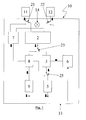
- FIG. 1 shows a 3D safety sensor 10 in measurement mode.
- the 3D security sensor 10 comprises a first camera 11, a second camera 12 and a control and evaluation unit 13.
- the control and evaluation unit 13 comprises an image evaluation unit 2, a comparator 3, a protection room violation output unit 5, a memory for protection space definition 6, a memory for test pattern 7, a disturbance detector 8, a disturbance output unit 9 and switches 21, 22, 23 and 25.
- a lighting unit 14 is provided, by means of which the spatial region in which the solid angle ranges, the cameras 11th or 12 are overlapped, can be provided, at least in some areas with a lighting structure having the properties inhomogeneous, aperiodic andsunä Republic.
- the first camera 11 is connected via the switch 21 to a first input of the image evaluation unit 2 and the second camera 12 via the switch 22 to a second input of the image evaluation unit 2.
- the output of the image evaluation unit 2 is connected via the switch 23 to a first input of the comparator 3, whose second input to the memory for protection space definition 6 connected is.
- the output of the comparator 3 is connected via the switch 25 to the protected space violation output unit 5.
- Two outputs of the memory for test pattern 7 are connected to the contact points of the switches 21, 22, which are not switched in the measuring mode, another connection is to an input of the fault detector 8.
- Other inputs of the fault detector 8 are connected to the contact points of the switches 23 and 25, which are not switched in measuring mode, connected.
- the output of the disturbance detector 8 is connected to the disturbance output unit 9 which serves to output the disturbance message.
- the images taken by the first camera 11 and the second camera 12 are supplied to the image evaluation unit 2 and processed therein into a 3D sensor image.
- This 3D sensor image is forwarded to the comparator 3, which performs a comparison with a stored in memory for shelter definition 6 3D sensor image for an undisturbed shelter. If agreement is found within the expected tolerance ranges between the recorded and the stored 3D sensor image, the protection space violation output unit 5 remains passive or outputs a signal "Protection room not injured". If 3 significant differences between the recorded and the stored sensor image found in the comparator, a violation of the shelter is detected and possibly triggered a safety function.
- the memory for test pattern 7, the disturbance detector 8 and the disturbance output unit 9 remain inoperative in this mode of operation.
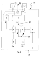
- FIG. 2 shows the 3D security sensor 10 according to FIG. 1 in a first test operation.
- the switches 21, 22, 23 and 25 are each brought into a second switching position.
- the first and the second input of the image evaluation unit 2 are each connected via the switches 21, 22 to an output of the memory for the test pattern 7.
- the image evaluation unit 2 the now defined test pattern, is tested from the memory for test pattern 7 are supplied as input data.
- the result of the processing of these input data by the image evaluation unit 2 is transmitted to the disturbance detector 8, in which it is compared with the correct result.
- This correct result can also be stored in the memory for test pattern 7 or, if the comparator 3 is designed to be suitable, also in the memory for protection space definition 6 and forwarded via the comparator 3 to the interference detector 8. If, within the expected tolerance ranges, correspondence is found between the output signal of the image evaluation unit 2 fed to the disturbance detector 8 and the correct result by the disturbance detector 8, then no result "disturbance" is forwarded to the disturbance output unit 9, otherwise this result is forwarded.
- the detection of a disturbance becomes particularly precise if the correct result is stored in the memory for protection space definition 6 and in the memory for test pattern 7, since in this embodiment, if there is a match within the expected tolerance ranges of the result of the above-described comparisons in the disturbance detector 8, clearly a malfunction the image evaluation unit 2 can be closed.
- FIG. 3 shows the 3D security sensor 10 according to FIG. 1 in a second test operation
- the switches 21, 22 and 25 are as in the first test operation according to FIG. 2 switched, but switch 23 as in the measuring operation according to FIG. 1 , Accordingly, in this operating mode, the output signal that the image evaluation unit 2 generates from the test pattern signals is forwarded to the comparator 3 and compared with the definition of the protective field or the protective fields stored in the memory for protection space definition 6.
- the disturbance detector 8 is operated to check whether the comparator 3 is correctly responding to the virtual guard space violations provoked for the test. If this is the case, there is no fault. If this is not the case, a fault exists either in the image evaluation unit 2, which can be detected in the first test operation, or in the comparator 3 or in the memory for the protection space definition 6. If the memory for the protection space definition 6 is adjusted so that it can be read out separately, for example by displaying it on a display, it is also easy to decide between these components which is working incorrectly.
- the fault output unit 9 receives the signal that there is a fault from Fault detector 8 and converts this into a fault message.
- FIG. 4 shows an embodiment of the invention, with which a third test operation can take place, which includes not only the actual control and evaluation electronics 13, but also the cameras 11, 12 in the functional test.
- the illustrated 3D safety sensor 10 largely corresponds to the in FIG. 1 illustrated 3D safety sensor.
- the image evaluation unit 2 has an additional output, via which data can be written into the memory for protection space functions 6 in a memory area reserved for this purpose.
- the illumination structure generated by the illumination unit 14 is also stored as a test pattern in the memory for test pattern 7.
- the position of the switches 21, 22 and 23 is identical to that in the case of the in FIG. 1 illustrated measuring operation, but the position of the switch 25 deviates from it, so that the output of the image evaluation unit 2 with and the output of the comparator 3 are each in communication with an input of the interference detector 8.
- the third test operation comprises the following steps: First, with the cameras 11, 12 an image is taken without illumination by the illumination unit 14 and evaluated in the image evaluation unit 2. The result of the evaluation is stored in the memory area provided for this purpose in the memory for protection space definitions 6. Subsequently, with the cameras 11, 12, a picture with structured illumination is taken by the illumination unit 14 which is now switched on, evaluated in the image evaluation unit 2 and via the output of the image evaluation unit 2 to an input of the comparator 3 supplied. At the other input of the comparator 3, the previously recorded image stored without illumination in the dedicated memory area of the memory for protection space definition 6 is provided, and the comparator 3 compares both images. The result of this comparison must provide the structure of the illumination, at least in some areas of the image.
- the output signal of the comparator 3 is applied to one input of the disturbance detector 8 and the illumination structure stored in the memory for test pattern 7 is applied to another input of the disturbance detector 8.
- the disturbance detector 8 compares both signals with each other; If they also do not agree in partial areas, then a fault message is output via the fault output unit 9, otherwise it is ensured that all components are functional.
Landscapes
- Engineering & Computer Science (AREA)
- General Engineering & Computer Science (AREA)
- Mechanical Engineering (AREA)
- Computer Vision & Pattern Recognition (AREA)
- Physics & Mathematics (AREA)
- General Physics & Mathematics (AREA)
- Length Measuring Devices By Optical Means (AREA)
- Alarm Systems (AREA)
- Geophysics And Detection Of Objects (AREA)
Abstract
Description
Die Erfindung betrifft einen 3D-Sicherheits-Sensor gemäß dem Oberbegriff des Patentanspruchs 1 und ein Verfahren zum Testen eines 3D-Sicherheits-Sensors gemäß dem Oberbegriff des Patentanspruchs 5.The invention relates to a 3D safety sensor according to the preamble of patent claim 1 and to a method for testing a 3D safety sensor according to the preamble of
Sicherheitssensoren finden breite Anwendung bei der Absicherung von Gefahrenbereichen, beispielsweise in Form von Lichtgittern. Allerdings ist diese Anwendung bislang fast ausschließlich auf das Überwachen von Grenzlinien und/oder Grenzflächen beschränkt und für die Überwachung von Räumen kaum verbreitet. Sollte tatsächlich ein Volumen überwacht werden müssen, wird dies in der Regel nach dem Stand der Technik durch eine Rasterung des Volumens mit Hilfe einer Vielzahl von flächigen Sicherheitssensoren, z.B. Lichtgittern, getan oder durch Einrichtung jeweils eines Sicherheitssensors für alle Grenzflächen, was zu hohem Materialaufwand und damit hohen Kosten führt.Safety sensors are widely used in the protection of hazardous areas, for example in the form of light curtains. However, this application has so far been limited almost exclusively to the monitoring of borderlines and / or interfaces and is hardly used for the surveillance of rooms. If, in fact, a volume is to be monitored, this is usually done in the prior art by screening the volume by means of a plurality of area safety sensors, e.g. Light grids, done or by setting up a safety sensor for all interfaces, resulting in high material costs and thus high costs.
Diese Beschränkung in der Anwendung ist nicht darauf zurückzuführen, dass 3D-Sensoren als solche technisch nicht verfügbar wären, auch wenn die Anforderungen an diese Systeme vielfältig sind und unter anderem die schnelle Erfassung einer Vielzahl von Entfernungsbildpunkten und Sicherstellung der Funktionsweise auf bei Auftreten jeglicher Art von optischer Störstrahlung und/oder optisch kritischen, z.B. glänzenden oder kontrastarmen Objekten umfassen.This limitation in use is not due to the fact that 3D sensors as such would be technically unavailable, even though the demands on these systems are manifold, including the rapid acquisition of a variety of range pixels and ensuring functionality on occurrence of any kind of comprise optical interference radiation and / or optically critical, eg shiny or low-contrast objects.
Für die Realisierung eines optoelektronischen 3D-Sensors, d.h. eines Sensors, der geeignet ist, ein Volumen im Raum zu überwachen, sind eine Reihe unterschiedlicher Verfahren bekannt:For the realization of an optoelectronic 3D sensor, i. of a sensor capable of monitoring a volume in space, a number of different methods are known:
Einerseits gibt es Flugzeit-basierte Verfahren, bei denen von einer Strahlungsquelle ein modulierter Lichtpuls ausgesendet, an dem Messobjekt reflektiert und detektiert wird, wobei die Laufzeit des Lichtpulses durch Ermittlung der Phasendifferenz des modulierten Lichtes bestimmt wird. Ein Beispiel für ein nach diesem Prinzip arbeitendes System lehrt beispielsweise die
Eine alternative Vorgehensweise bei der Realisation eines 3D-Sensors, die z.B. der
Schließlich werden auch noch als 3D-Sensor "traditionelle" Stereokameras verwendet, die die Information zweier unabhängiger optoelektronischer Sensoren, deren fortan als Raumwinkelbereiche oder kurz Raumwinkel bezeichnete Gesichtsfelder, d.h. die Bereiche, in denen sie einen Gegenstand nachweisen können, sich überlappen, so miteinander verrechnen, dass über die Triangulation der Daten der Sensoren eine Tiefeninformation den jeweiligen Bildpunkten zugeordnet werden kann. Zur automatisierten Bestimmung dieses Maßes im 3D-Sensor ist es also notwendig, die Verlagerung des Gegenstands in den beiden Bildern automatisiert zu berechnen. Die Präzision, mit der dies gelingt, hängt entscheidend vom Kontrast des Gegenstands und dem Kontrast des Gegenstands gegenüber dem Hintergrund ab.Finally, even as a 3D sensor "traditional" stereo cameras are used, the information of two independent optoelectronic sensors, hereafter referred to as solid angle ranges or short solid angle fields of view, i. the areas in which they can detect an object, overlap, compute with each other so that via the triangulation of the data of the sensors, a depth information can be assigned to the respective pixels. For the automated determination of this measure in the 3D sensor, it is therefore necessary to automatically calculate the displacement of the object in the two images. The precision with which this succeeds depends crucially on the contrast of the object and the contrast of the object against the background.
Darüber hinaus ergibt sich aber bei der Anwendung aller genannten Arten von 3D-Sensoren in sicherheitsrelevanten Applikationen die Schwierigkeit, dass für diesen Einsatz ein ausgereiftes Überwachungssystem die störungsfreie Funktion des 3D-Sensors zu jedem Zeitpunkt oder die Ausgabe einer Störungsmeldung sicherstellen muss. Dafür sind zwei Ansätze aus dem Stand der Technik bekannt:In addition, however, the application of all the above-mentioned types of 3D sensors in safety-relevant applications results in the difficulty that a sophisticated monitoring system must ensure the trouble-free functioning of the 3D sensor at all times or the output of a fault message for this application. Two approaches from the prior art are known for this purpose:
Die
Aus der
Aus der
Die
Problematisch ist hierbei, dass die beiden gemäß der Lehre der
Die Aufgabe der Erfindung besteht darin, einen robusten und preisgünstigen 3D-Sicherheits-Sensor insbesondere für industrielle Anwendungen und ein Verfahren zum Testen eines solchen 3D-Sensors bereitzustellen.The object of the invention is to provide a robust and inexpensive 3D safety sensor, in particular for industrial applications, and a method for testing such a 3D sensor.
Diese Aufgabe wird gelöst durch einen 3D-Sicherheits-Sensor mit den Merkmalen des Anspruchs 1 und ein Verfahren zum Testen eines 3D-Sicherheits-Sensors mit den Merkmalen des Anspruchs 5.This object is achieved by a 3D safety sensor having the features of claim 1 and a method for testing a 3D safety sensor having the features of
Vorteilhafte Ausführungen und Weiterbildungen der Erfindung sind in den jeweils rückbezogenen Unteransprüchen angegeben.Advantageous embodiments and modifications of the invention are specified in the respective dependent subclaims.
Der Erfindung liegt die Erkenntnis zugrunde, dass durch Vorsehen eines von den anderen Komponenten des 3D-Sicherheits-Sensors völlig unabhängigen zusätzlichen Signalverarbeitungszweiges, umfassend einen Speicher für Testmuster, einen Störungsdetektor und eine Störungs-Ausgangseinheit in einer an sich vorbekannten Auswerte- und Steuereinheit eine Prüfung der Einzelkomponenten erfolgen kann und die Voraussetzung für eine Funktionsüberwachung der einzelnen Komponenten des 3D-Sicherheits-Sensors geschaffen werden kann.The invention is based on the finding that, by providing an additional signal processing branch which is completely independent of the other components of the 3D safety sensor, comprising a memory for test patterns, a fault detector and a fault output unit in a previously known evaluation and control unit the individual components can be made and the condition for a functional monitoring of the individual components of the 3D safety sensor can be created.
Dabei werden in dem getrennten Speicher für Testmuster Testmuster abgelegt, die alternativ zu den Kameradaten der Auswerteeinheit zugeführt werden. Diese Testmuster können beispielsweise aus geometrisch angeordneten Grauwertverläufen und Kontrastveränderungen oder Objekten der notwendigen Größe und Anzahl, um eine Verletzung des Schutzbereiches hervorzurufen, bestehen und erlauben bei geschickter Ausführung, den gesamten Arbeitsbereich der Auswerteeinheit mit nur einem Testmusterpaar auf korrekte Funktion zu prüfen. Die Überprüfung erfolgt durch anschließenden Vergleich des aktuell ausgewerteten Bildes mit einem im Speicher für Testmuster hinterlegten Soll-Bild im Störungsdetektor. Wird dabei ein über zulässige Toleranzen hinausgehender Unterschied festgestellt, wird über die Störungs-Ausgangseinheit eine Störung gemeldet.In this case test patterns are stored in the separate memory for test patterns, which are fed to the evaluation unit as an alternative to the camera data. These test patterns can consist, for example, of geometrically arranged gray scale gradients and contrast changes or objects of the required size and number in order to cause a violation of the protected area, and, with a clever design, allow the entire work area of the evaluation unit to be tested for correct function with only one test pattern pair. The check is carried out by subsequent comparison of the currently evaluated image with a stored in the memory for test pattern target image in the interference detector. If a difference exceeding permissible tolerances is detected, a fault is reported via the fault output unit.
Die Funktion des Vergleichers kann überprüft werden, indem durch den Störungsdetektor überwacht wird, ob ein in die Auswerteeinheit eingespeistes Testmuster, das aus Objekten der notwendigen Größe und Anzahl besteht, um eine Verletzung des Schutzbereiches hervorzurufen, die für eine vorliegende Schutzbereichsverletzung definierte Reaktion des Vergleichers hervorruft.The function of the comparator can be checked by monitoring by the disturbance detector whether a test pattern fed into the evaluation unit, consisting of objects of the necessary size and number, causes a violation of the protected area, causing the comparator to respond defined for a present protection area violation ,
Für eine zuverlässige Funktionsüberprüfung des 3D-Sicherheits-Sensors ist sicherzustellen, dass die Testmuster und das zugeordnete Sollergebnis nach der Inbetriebnahme des 3D-Sicherheits-Sensors nicht mehr verändert werden können.For a reliable functional check of the 3D safety sensor, it must be ensured that the test patterns and the associated target result can no longer be changed after the 3D safety sensor has been put into operation.
Der erfindungsgemäße 3D-Sicherheits-Sensor umfasst eine erste Kamera und eine zweite Kamera, die so zueinander ausgerichtet sind, dass ihre Raumwinkelbereiche sich überlappen, und eine Steuer- und Auswerteeinheit umfassend eine Bildauswerteeinheit, einen Vergleicher, einen Speicher für Schutzraumdefinition und eine Schutzraumverletzungs-Ausgangseinheit, wobei zusätzlich ein Speicher für Testmuster, ein Störungsdetektor und eine Störungs-Ausgangseinheit vorgesehen sind. Mit Hilfe dieser Komponenten ist es, wie weiter unten detailliert dargelegt wird, möglich, eine Funktionskontrolle der zum Nachweis einer Schutzraumverletzung notwendigen Komponenten der Steuer- und Auswerteeinheit durchzuführen und eine Fehlfunktion nicht nur nachzuweisen, sondern auch sicher einer Komponente zuzuordnen. Es bestehen Signalverbindungen zumindest zwischen einem Ausgang des Speichers für Testmuster und einem Eingang des Störungsdetektors, zwischen einem Ausgang des Störungsdetektors und einem Eingang der Störungs-Ausgangseinheit sowie zwischen einem Ausgang des Speichers für Schutzraumdefinitionen und einem Eingang des Vergleichers. Zwei Eingänge der Bildauswerteeinheit sind über Schalter wahlweise mit jeweils einem Ausgang einer Kamera oder mit jeweils einem Ausgang des Speichers für Testmuster verbindbar. Weiter ist ein Ausgang der Bildauswerteeinheit über einen Schalter jeweils wahlweise mit einem Eingang des Vergleichers oder mit einem Eingang des Störungsdetektors verbindbar und/oder ein Ausgang des Vergleichers über einen Schalter jeweils wahlweise mit einem Eingang der Schutzraumverletzungs-Ausgangseinheit oder mit einem Eingang des Störungsdetektors verbindbar.The inventive 3D safety sensor comprises a first camera and a second camera, which are aligned with one another such that their solid angle ranges overlap, and a control and evaluation unit comprising an image evaluation unit, a comparator, a storage space for protection space definition and a protected space violation output unit In addition, a memory for test pattern, a disturbance detector and a disturbance output unit are provided. With the aid of these components, as detailed below, it is possible to carry out a functional check of the components of the control and evaluation unit necessary for the detection of a trauma injury and not only to detect a malfunction, but also to assign it to a component safely. There are signal connections at least between an output of the test pattern memory and an input of the disturbance detector, between an output of the disturbance detector and an input of the disturbance output unit and between an output of the memory space definitions memory and an input of the comparator. Two inputs of the image evaluation unit can be connected via switches either with one output of a camera or with one output of the memory for test patterns. Furthermore, an output of the image evaluation unit can be connected in each case optionally to an input of the comparator or to an input of the disturbance detector and / or an output of the comparator can be connected via a switch optionally to an input of the protected space violation output unit or to an input of the disturbance detector.
Gemäß einer bevorzugten Ausführungsform ist vorgesehen, dass zusätzlich eine Signalverbindung zwischen einem Ausgang der Bildauswerteeinheit und einem Speicherbereich des Speichers für Schutzraumdefinitionen vorhanden ist, über die Ergebnisse der Auswertung in der Bildauswerteeinheit im dafür vorgesehenen Speicherbereich des Speichers für Schutzraumdefinitionen speicherbar sind. Diese Anordnung erlaubt nämlich eine direkte Definition des Schutzraumes dadurch, dass ein Resultat der Bildauswerteeinheit, das auf Bildern der Kameras basiert, die zu einem Zeitpunkt aufgenommen werden, zu dem sichergestellt ist, dass keine Schutzraumverletzung vorliegt, als Schutzraumdefinition verfügbar gemacht wird. Dies ist insbesondere bei sich schnell verändernden Schutzräumen eine große Arbeitserleichterung. Die Schutzraumdefinitionen können im Speicher für Schutzraumdefinitionen aber auch auf andere Weise hinterlegt werden.According to a preferred embodiment it is provided that in addition there is a signal connection between an output of the image evaluation unit and a memory area of the memory for protection space definitions, via which results of the evaluation in the image evaluation unit can be stored in the memory area of the memory for protection space definitions provided for this purpose. Namely, this arrangement allows a direct definition of the protection space by making a result of the image evaluation unit based on images of the cameras taken at a time when it is ensured that there is no protection space violation available as a protection space definition. This is a great deal easier, especially with rapidly changing shelters. The protection space definitions can also be stored in the memory for protection space definitions in other ways.
Besonders vorteilhaft ist es, zusätzlich eine Beleuchtungseinheit vorzusehen, mittels derer der Raumbereich, in dem sich die Raumwinkelbereiche, die von den Kameras erfasst werden, überlappen, zumindest in Teilbereichen mit einer Beleuchtungsstruktur versehbar ist, die die Eigenschaften inhomogen, aperiodisch und selbstunähnlich aufweist. Durch die inhomogene Beleuchtung wird ein Bildkontrast im überwachten Schutzraum erzeugt. Der Vergleich eines mit Beleuchtung aufgenommenem Bildes des Schutzraums mit einem ohne Beleuchtung aufgenommenen Bild mit Hilfe des Vergleichers muss dann zumindest in Teilbereichen des Bildes das Beleuchtungsmuster reproduzieren. Dies kann im Störungsdetektor durch Vergleich des Ausgangssignals des Vergleichers mit der im Speicher für Testmuster hinterlegten Beleuchtungsstruktur erfolgen.It is particularly advantageous to additionally provide a lighting unit, by means of which the spatial area in which the solid angle ranges which are detected by the cameras overlap can be provided, at least in partial areas, with an illumination structure which has the properties inhomogeneous, aperiodic and even dissimilar. The inhomogeneous illumination creates a contrast in the monitored shelter. The comparison of an image taken with illumination of the shelter with an image taken without illumination using the comparator must then reproduce the illumination pattern at least in partial areas of the image. This can be done in the interference detector by comparing the output of the comparator with the stored in the memory for test pattern illumination structure.
Mit einem Beleuchtungsmuster, das nicht wenigstens in einem Teilbereich aperiodisch und selbstunähnlich ist, wäre zum Beispiel eine Fehljustage der Kameras nicht eindeutig festzustellen, wie sich leicht am Beispiel eines Schachbrettmusters als Beleuchtungsstruktur erschließt: Liegen ein weißes Feld des ersten Bildes und ein schwarzes Feld des zweiten Bildes zunächst übereinander, können die Bilder durch eine Verschiebung um ein Feld in waagerechter Richtung oder durch ein Verschiebung um ein Feld in senkrechter Richtung oder durch eine Vielzahl von Linearkombination dieser Verschiebungen in Übereinstimmung gebracht werden. Auch fehljustierte Kameras können dann zum scheinbar richtigen Ergebnis führen, obwohl die Sicherheitsfunktion korrumpiert ist. Um solche Mehrdeutigkeiten zu vermeiden, muss es mindestens einen Teilbereich des inhomogenen Beleuchtungsmusters geben, der aperiodisch und selbstunähnlich ist.With a lighting pattern that is not aperiodic and selbstunähnlich at least in a subarea, for example, a misalignment of the cameras would not be unambiguous to determine, as easily on the example of a checkerboard pattern as illuminating structure opens: a white field of the first image and a black field of the second If the images are initially superimposed, the images can be made to coincide by a shift around a field in a horizontal direction or by a shift around a field in the vertical direction or by a multiplicity of linear combinations of these shifts. Even misaligned cameras can then lead to the seemingly correct result, even though the safety function is corrupted. To avoid such ambiguities, there must be at least a portion of the inhomogeneous illumination pattern that is aperiodic and self-dissimilar.
Besonders vorteilhaft ist es, wenn die Bildauswerteeinheit vollständig in Hardware realisiert ist, da dadurch besonders gut industrielle Anforderungen im Bereich der Maschinenabsicherung insbesondere in Bezug auf Reaktionszeit erfüllt werden können. Dazu werden Rechenalgorithmen in ihre einzelnen Schritte zerlegt und anschließend in einer applikationsspezifischen integrierten Schaltung (ASIC) realisiert, und zwar bevorzugt in der Ausführung als FPGA (Field Programmable Gate Array). Bei geschickter Wahl und Ausführung des an sich bekannten Verfahrens lassen sich Verarbeitungsgeschwindigkeiten von wenigen Millisekunden für die Auswertung eines Stereobildpaares erreichen. Gleichzeitig gibt eine so hohe Verarbeitungsgeschwindigkeit die Möglichkeit, Testphasen des 3D-Sicherheits-Sensors wiederholt in Messphasen einzufügen, ohne die Ansprechzeit des 3D-Sicherheits-Sensors und damit seine Verfügbarkeit für die Schutzbereichsüberwachung unzulässig lange zu unterbrechen.It is particularly advantageous if the image evaluation unit is completely realized in hardware, since this makes it possible to fulfill industrial requirements in the field of machine protection, in particular with regard to reaction time, in a particularly good manner. For this purpose, computational algorithms are broken down into their individual steps and subsequently implemented in an application-specific integrated circuit (ASIC), preferably in the form of an FPGA (Field Programmable Gate Array). With skillful choice and execution of the known per se processing speeds of a few milliseconds can be achieved for the evaluation of a stereo image pair. At the same time, such a high processing speed makes it possible to repeatedly insert test phases of the 3D safety sensor into measuring phases, without the response time of the 3D safety sensor and thus its Unavailable interruption of availability for protection zone monitoring.
Das erfindungsgemäße Verfahren zum Testen eines erfindungsgemäßen 3D-Sicherheits-Sensors umfasst die Schritte Speichern von Testmustern in einem Speicher für Testmuster, Zuführen eines Testmusters zu einer Bildauswerteeinheit alternativ zu den Kameradaten, Prüfen der Bildauswerteeinheit auf korrekte Funktion durch Vergleich des in Form eines der Testmuster zugeführten, aktuell ausgewerteten Bildes mit einem im Speicher für Testmuster hinterlegten Soll-Bild in einem Störungsdetektor und Melden einer Störung über eine Störungs-Ausgangseinheit, wenn dabei ein über zulässige Toleranzen hinausgehender Unterschied festgestellt wird.The method according to the invention for testing a 3D safety sensor according to the invention comprises the steps of storing test patterns in a memory for test patterns, supplying a test pattern to an image evaluation unit as an alternative to the camera data, checking the image evaluation unit for correct function by comparing it in the form of one of the test patterns , Currently evaluated image with a stored in the memory for test pattern target image in a fault detector and reporting a fault on a fault output unit, if it is determined beyond permissible tolerances difference is detected.
In einer besonders vorteilhaften Ausführungsform werden auch Fehlfunktionen des Vergleichers nachgewiesen, indem ferner die Schritte Überprüfen der Funktion eines Vergleichers durch Überwachung, ob ein aus dem Speicher für Testmuster in die Bildauswerteeinheit eingespeistes Testmuster, das aus Objekten der notwendigen Größe und Anzahl besteht, um eine Verletzung des Schutzbereiches hervorzurufen, die für eine vorliegende Schutzbereichsverletzung definierte Reaktion des Vergleichers hervorruft, durch den Störungsdetektor und Melden einer Störung über die Störungs-Ausgangseinheit, falls dies nicht der Fall ist, ausgeführt werden.In a particularly advantageous embodiment, malfunctions of the comparator are also detected by further checking the steps of checking the function of a comparator by monitoring whether a test pattern fed from the memory for test patterns into the image evaluation unit and consisting of objects of the necessary size and number is an injury of the protection area causing the comparator response defined for a present protection area violation, by the disturbance detector and reporting a disturbance via the disturbance output unit if this is not the case.
Der optische Zweig des 3D-Sicherheits-Sensors kann in die Funktionsüberwachung einbezogen werden, indem das Verfahren um die Schritte Bereitstellen eines Beleuchtungsmusters im Speicher für Testmuster, Aufnehmen eines ersten Bildes eines zu überwachenden Schutzraums ohne mit dem Beleuchtungsmuster strukturierte Beleuchtung, Auswerten des aufgenommenen ersten Bildes in der Bildauswerteeinheit, Speichern des ausgewerteten ersten Bildes in einem dafür vorgesehenen Bereich des Speichers für Schutzraumdefinitionen, Aufnehmen eines zweiten Bildes eines zu überwachenden Schutzraums mit strukturierter Beleuchtung, Auswerten des aufgenommenen zweiten Bildes in der Bildauswerteeinheit, Vergleichen des ausgewerteten zweiten Bildes mit dem aus dem Speicher für Schutzraumdefinitionen bereitgestellten ausgewerteten ersten Bild im Vergleicher, Vergleichen des Ergebnisses des Vergleichers mit der im Speicher für Testmuster bereitgestellten Beleuchtungsstruktur im Störungsdetektor und Melden einer Störung über die Störungs-Ausgangseinheit, falls der Vergleich negativ ausfällt, erweitert wird.The optical branch of the 3D security sensor may be included in the performance monitoring by the method of providing an illumination pattern in the memory for test patterns, taking a first image of a protected space to be monitored without illumination patterned with the illumination pattern, evaluating the recorded first Image in the image evaluation unit, storing the evaluated first image in a designated area of the memory for protection space definitions, taking a second image of a protected space to be monitored with structured illumination, evaluating the recorded second image in the image evaluation unit, comparing the evaluated second image with that from the Memory for protection space definitions provided evaluated first image in the comparator, comparing the result of the comparator with the provided in the memory for test pattern lighting structure in the fault detector and reporting a fault on the fault output unit, if the comparison is negative, expanded.
Dabei ist es sinnvoll, die beschriebenen Abfolgen von Schritten zur Funktionskontrolle des 3D-Sicherheits-Sensors jeweils zwischen Phasen regulären Messbetriebs des Sensors durchzuführen.In this case, it makes sense to carry out the described sequences of steps for the functional check of the 3D safety sensor in each case between phases of regular measuring operation of the sensor.
Im Folgenden wird eine Ausführungsform der Erfindung anhand der beigefügten Zeichnungen näher erläutert.In the following, an embodiment of the invention is explained in more detail with reference to the accompanying drawings.
Es zeigt
- Fig. 1:
- einen 3D-Sicherheits-Sensor gemäß einer Ausführungs- form der Erfindung während des Messbetriebs,
- Fig. 2:
- den 3D-Sicherheits-Sensor aus
Figur 1 während einer ersten Testbetriebsart, - Fig. 3:
- den 3D-Sicherheits-Sensor aus
Figur 1 während einer zweiten Testbetriebsart und - Fig. 4:
- den 3D-Sicherheits-Sensor aus
Figur 1 während einer dritten Testbetriebsart.
- Fig. 1:
- a 3D safety sensor according to an embodiment of the invention during the measuring operation,
- Fig. 2:
- the 3D security sensor off
FIG. 1 during a first test mode, - 3:
- the 3D security sensor off
FIG. 1 during a second test mode and - 4:
- the 3D security sensor off
FIG. 1 during a third test mode.
Da alle Figuren eine Ausführungsform der Erfindung zeigen, die dieselben Komponenten umfasst, die lediglich anders miteinander verschaltet sind, werden für die Komponenten in allen Figuren dieselben Bezugszeichen verwendet. Um die Unterscheidung zwischen Ein- und Ausgängen der Komponenten zu erleichtern, wird die Richtung des Signalflusses auf den Verbindungen zwischen den Komponenten durch Pfeile angegeben.Since all figures show an embodiment of the invention which comprises the same components, which are merely interconnected differently, the same reference numerals are used for the components in all figures. To facilitate the distinction between inputs and outputs of the components, the direction of the signal flow on the connections between the components is indicated by arrows.
Im in
Zwei Ausgänge des Speichers für Testmuster 7 sind mit den Kontaktpunkten der Schalter 21, 22, die im Messbetrieb nicht geschaltet sind, verbunden, eine weitere Verbindung besteht zu einem Eingang des Störungsdetektors 8. Weitere Eingänge des Störungsdetektors 8 sind mit den Kontaktpunkten der Schalter 23 und 25, die im Messbetrieb nicht geschaltet sind, verbunden. Der Ausgang des Störungsdetektors 8 ist mit der Störungs-Ausgangseinheit 9, die zur Ausgabe der Störungsmeldung dient, verbunden.Two outputs of the memory for
Bei der vorstehend beschriebenen Verschaltung der Steuer- und Auswerteeinheit 13 werden die von der ersten Kamera 11 und der zweiten Kamera 12 aufgenommenen Bilder der Bildauswerteeinheit 2 zugeführt und in dieser zu einem 3D-Sensorbild verarbeitet. Dieses 3D-Sensorbild wird an den Vergleicher 3 weitergeleitet, der einen Vergleich mit einem im Speicher für Schutzraumdefinition 6 hinterlegten 3D-Sensorbild für einen ungestörten Schutzraum durchführt. Wird Übereinstimmung innerhalb der zu erwartenden Toleranzbereiche zwischen dem aufgenommenen und dem hinterlegten 3D-Sensorbildes festgestellt, bleibt die Schutzraumverletzungs-Ausgangseinheit 5 passiv oder gibt ein Signal "Schutzraum nicht verletzt" aus. Werden im Vergleicher 3 signifikante Unterschiede zwischen dem aufgenommenen und dem hinterlegten Sensorbild gefunden, wird eine Verletzung des Schutzraums festgestellt und gegebenenfalls eine Sicherheitsfunktion ausgelöst.In the above-described interconnection of the control and
Der Speicher für Testmuster 7, der Störungsdetektor 8 und die Störungs-Ausgangseinheit 9 bleiben in diesem Betriebsmodus funktionslos.The memory for
Im ersten Testbetrieb sind die Schalter 21, 22, 23 und 25 jeweils in eine zweite Schaltposition gebracht. Damit sind nun der erste und der zweite Eingang der Bildauswerteeinheit 2 jeweils über die Schalter 21, 22 mit einem Ausgang des Speichers für die Testmuster 7 verbunden. Außerdem besteht eine Verbindung zwischen dem Ausgang der Bildauswerteeinheit 2 und dem Störungsdetektor 8 über den Schalter 23 sowie zwischen dem Ausgang des Vergleichers 3 und dem Störungsdetektor 8 über den Schalter 25. Getestet wird in diesem Testbetrieb die Bildauswerteeinheit 2, der nun definierte Testmuster aus dem Speicher für Testmuster 7 als Eingangsdaten zugeführt werden. Das Ergebnis der Verarbeitung dieser Eingangsdaten durch die Bildauswerteeinheit 2 wird an den Störungsdetektor 8 übermittelt, in dem es mit dem korrekten Ergebnis verglichen wird. Dieses korrekte Ergebnis kann ebenfalls im Speicher für Testmuster 7 oder, falls der Vergleicher 3 dafür geeignet ausgelegt ist, auch im Speicher für Schutzraumdefinition 6 gespeichert sein und über den Vergleicher 3 an den Störungsdetektor 8 weitergeleitet werden. Wird innerhalb der zu erwartenden Toleranzbereiche Übereinstimmung zwischen dem dem Störungsdetektor 8 zugeleiteten Ausgangssignal der Bildauswerteeinheit 2 und dem korrekten Ergebnis durch den Störungsdetektor 8 festgestellt, so wird kein Ergebnis "Störung" an die Störungs-Ausgangseinheit 9 weitergeleitet, andernfalls wird dieses Ergebnis weitergeleitet.In the first test operation, the
Besonders präzise wird der Nachweis einer Störung, wenn das korrekte Ergebnis im Speicher für Schutzraumdefinition 6 und im Speicher für Testmuster 7 gespeichert ist, da in dieser Ausführungsform bei Übereinstimmung innerhalb der zu erwartenden Toleranzbereiche des Resultats der oben beschriebenen Vergleiche im Störungsdetektor 8 eindeutig auf eine Fehlfunktion der Bildauswerteeinheit 2 geschlossen werden kann.The detection of a disturbance becomes particularly precise if the correct result is stored in the memory for
Im zweiten Testbetrieb sind die Schalter 21, 22 und 25 wie im ersten Testbetrieb gemäß
Falls eine Störung vorliegt, empfängt die Störungs-Ausgangseinheit 9 das Signal, dass eine Störung vorliegt, vom Störungsdetektor 8 und setzt dieses in eine Störungsmeldung um.If there is a fault, the
Der dargestellte 3D-Sicherheits-Sensor 10 entspricht weitgehend dem in
Der dritte Testbetrieb umfasst die folgenden Schritte: Zunächst wird mit den Kameras 11, 12 ein Bild ohne Beleuchtung durch die Beleuchtungseinheit 14 aufgenommen und in der Bildauswerteeinheit 2 ausgewertet. Das Ergebnis der Auswertung wird in dem dafür vorgesehenen Speicherbereich im Speicher für Schutzraumdefinitionen 6 gespeichert. Anschließend wird mit den Kameras 11, 12 ein Bild mit strukturierter Beleuchtung durch die nun eingeschaltete Beleuchtungseinheit 14 aufgenommen, in der Bildauswerteeinheit 2 ausgewertet und über den Ausgang der Bildauswerteeinheit 2 einem Eingang des Vergleichers 3 zugeführt. Am anderen Eingang des Vergleichers 3 wird das im dafür vorgesehenen Speicherbereich des Speichers für Schutzraumdefinition 6 gespeicherte zuvor aufgenommenen Bild ohne Beleuchtung bereitgestellt, und der Vergleicher 3 vergleicht beide Bilder. Das Ergebnis dieses Vergleichs muss zumindest in Teilbereichen des Bildes die Struktur der Beleuchtung ergeben. Um festzustellen, ob dies der Fall ist, wird das Ausgangssignal des Vergleichers 3 an einen Eingang des Störungsdetektors 8 angelegt und die im Speicher für Testmuster 7 hinterlegte Beleuchtungsstruktur am einem anderen Eingang des Störungsdetektors 8. Der Störungsdetektor 8 vergleicht beide Signale miteinander; stimmen sie auch nicht in Teilbereichen überein, so wird über die Störungs-Ausgangseinheit 9 eine Störungsmeldung ausgegeben, andernfalls ist sichergestellt, dass alle Komponenten funktionstüchtig sind.The third test operation comprises the following steps: First, with the
Es ist allerdings stets bei der Definition des Kriteriums, das zur Bewertung, ob eine Übereinstimmung vorliegt oder nicht, darauf zu achten, dass bei dem so durchgeführten Vergleich wegen der Verwendung realen Beleuchtungsdaten keine absolute Identität insbesondere im Hinblick auf die Intensität der Beleuchtungsmuster erwartet werden kann sondern gegebenenfalls nur darauf abzustellen ist, dass Strukturen in der Beleuchtung wiedergefunden werden.However, it is always important in the definition of the criterion for assessing whether there is a match or not, that in the comparison thus made, due to the use of real illumination data, no absolute identity can be expected, in particular with regard to the intensity of the illumination patterns but if necessary only to make sure that structures are found in the lighting.
Durch Durchführung der drei Testbetriebsarten lässt sich damit sicherstellen, dass jede für die Feststellung einer Schutzraumverletzung notwendige Komponente einwandfrei funktioniert, und in dem Fall, dass eine Fehlfunktion einer Komponente auftritt, eine Identifikation dieser Komponente durchführen.By performing the three test modes, it is possible to ensure that each component necessary for the detection of a trauma violation functions properly and, in the event that a malfunction of a component occurs, to identify this component.
- 22
- Bildauswerteeinheitimage evaluation
- 33
- Vergleichercomparator
- 55
- Schutzraumverletzungs-AusgangseinheitShelter Injury output unit
- 66
- Speicher für SchutzraumdefinitionMemory for shelter definition
- 77
- Speicher für TestmusterMemory for test patterns
- 88th
- Störungsdetektorinterference detector
- 99
- Störungs-AusgangseinheitFault output unit
- 1010
- 3D-Sicherheits-Sensor3D Security Sensor
- 1111
- erste Kamerafirst camera
- 1212
- zweite Kamerasecond camera
- 1313
- Steuer- und AuswerteeinheitControl and evaluation unit
- 1414
- Beleuchtungseinheitlighting unit
- 2121
- Schalterswitch
- 2222
- Schalterswitch
- 2323
- Schalterswitch
- 2525
- Schalterswitch
Claims (7)
dadurch gekennzeichnet, dass zusätzlich ein Speicher für Testmuster (7), ein Störungsdetektor (8) und eine Störungs-Ausgangseinheit (9) vorgesehen sind, dass Signalverbindungen zumindest zwischen einem Ausgang des Speichers für Testmuster (7) und einem Eingang des Störungsdetektors (8), zwischen einem Ausgang des Störungsdetektors (8) und einem Eingang der Störungs-Ausgangseinheit (9) sowie zwischen einem Ausgang des Speichers für Schutzraumdefinitionen (6) und einem Eingang des Vergleichers (3) bestehen, dass zwei Eingänge der Bildauswerteeinheit (2) über Schalter (21, 22) wahlweise mit jeweils einem Ausgang einer Kamera (11, 12) oder mit jeweils einem Ausgang des Speichers für Testmuster (7) verbindbar sind und dass ein Ausgang der Bildauswerteeinheit (2) über einen Schalter (23) jeweils wahlweise mit einem Eingang des Vergleichers (3) oder mit einem Eingang des Störungsdetektors (8) verbindbar ist und/oder ein Ausgang des Vergleichers (3) über einen Schalter (25) jeweils wahlweise mit einem Eingang der Schutzraumverletzungs-Ausgangseinheit (5) oder mit einem Eingang des Störungsdetektors (8) verbindbar ist.A 3D security sensor (10) comprising a first camera (11) and a second camera (12) which are aligned so that their solid angle ranges overlap, and a control and evaluation unit (14) comprising an image evaluation unit (2) a comparator (3), a memory for protection space definition (6) and a protection space violation output unit (5),
characterized in that in addition a memory for test pattern (7), a disturbance detector (8) and a disturbance output unit (9) are provided, that signal connections at least between an output of the memory for test pattern (7) and an input of the disturbance detector (8) between an output of the disturbance detector (8) and an input of the disturbance output unit (9) and between an output of the memory for protection space definitions (6) and an input of the comparator (3), that two inputs of the image evaluation unit (2) via switches (21, 22) either with one output of a camera (11, 12) or with one output of the memory for test pattern (7) are connectable and that an output of the image evaluation unit (2) via a switch (23) each optionally with a Input of the comparator (3) or with an input of the fault detector (8) is connectable and / or an output of the comparator (3) via a switch (25) jewe is selectively connectable to an input of the protected space violation output unit (5) or to an input of the fault detector (8).
dadurch gekennzeichnet, dass zusätzlich eine Signalverbindung zwischen einem Ausgang der Bildauswerteeinheit (2) und einem Speicherbereich des Speichers für Schutzraumdefinitionen (6) vorgesehen ist, über die Ergebnisse der Auswertung in der Bildauswerteeinheit (2) im vorgesehenen Speicherbereich des Speichers für Schutzraumdefinitionen (6) speicherbar sind.3D safety sensor according to claim 1,
characterized in that in addition a signal connection between an output of the image evaluation unit (2) and a memory area of the memory for protection space definitions (6) is provided on the results of the evaluation in the image evaluation unit (2) in the designated memory area of the memory for protection space definitions (6) storable are.
dadurch gekennzeichnet, dass zusätzlich eine Beleuchtungseinheit (14) vorgesehen ist, mittels derer der Raumbereich, in dem sich die Raumwinkelbereiche, die von den Kameras (11, 12) erfasst werden, überlappen, zumindest in Teilbereichen mit einer Beleuchtungsstruktur versehbar sind, die die Eigenschaften inhomogen, aperiodisch und selbstunähnlich aufweist.3D safety sensor according to claim 1 or 2,
characterized in that in addition a lighting unit (14) is provided, by means of which the spatial region in which the solid angle ranges, which are detected by the cameras (11, 12) overlap, be providable, at least in partial areas with a lighting structure, the properties inhomogeneous, aperiodic and self-similar.
dadurch gekennzeichnet, dass die Bildauswerteeinheit (2) vollständig in Hardware realisiert ist.3D safety sensor according to any preceding claim,
characterized in that the image evaluation unit (2) is completely realized in hardware.
Priority Applications (3)
| Application Number | Priority Date | Filing Date | Title |
|---|---|---|---|
| EP07014270A EP2017571B1 (en) | 2007-07-20 | 2007-07-20 | 3D security sensor and method for testing a 3D security sensor |
| DE502007002747T DE502007002747D1 (en) | 2007-07-20 | 2007-07-20 | 3D safety sensor and method for testing a 3D safety sensor |
| AT07014270T ATE456783T1 (en) | 2007-07-20 | 2007-07-20 | 3D SECURITY SENSOR AND METHOD FOR TESTING A 3D SECURITY SENSOR |
Applications Claiming Priority (1)
| Application Number | Priority Date | Filing Date | Title |
|---|---|---|---|
| EP07014270A EP2017571B1 (en) | 2007-07-20 | 2007-07-20 | 3D security sensor and method for testing a 3D security sensor |
Publications (2)
| Publication Number | Publication Date |
|---|---|
| EP2017571A1 true EP2017571A1 (en) | 2009-01-21 |
| EP2017571B1 EP2017571B1 (en) | 2010-01-27 |
Family
ID=38669529
Family Applications (1)
| Application Number | Title | Priority Date | Filing Date |
|---|---|---|---|
| EP07014270A Not-in-force EP2017571B1 (en) | 2007-07-20 | 2007-07-20 | 3D security sensor and method for testing a 3D security sensor |
Country Status (3)
| Country | Link |
|---|---|
| EP (1) | EP2017571B1 (en) |
| AT (1) | ATE456783T1 (en) |
| DE (1) | DE502007002747D1 (en) |
Cited By (1)
| Publication number | Priority date | Publication date | Assignee | Title |
|---|---|---|---|---|
| EP2818824B1 (en) * | 2013-06-28 | 2015-09-16 | Sick Ag | Apparatus comprising an optoelectronic 3D-sensor and method for recognising objects |
Citations (5)
| Publication number | Priority date | Publication date | Assignee | Title |
|---|---|---|---|---|
| EP0902402A2 (en) | 1997-09-15 | 1999-03-17 | rms kleine gmbh vertrieb elektonischer geräte | Method for optically monitoring a space |
| DE10017344C1 (en) * | 2000-04-07 | 2001-11-29 | Pilz Gmbh & Co | Protective device for safeguarding a dangerous area and method for checking its functional safety has an image capture unit with an image sensor containing multiple light-sensitive image points. |
| WO2004029502A1 (en) * | 2002-09-24 | 2004-04-08 | Pilz Gmbh & Co. Kg | Method and device for making a hazardous area safe |
| US20060187303A1 (en) | 2002-11-16 | 2006-08-24 | Hans-Dieter Bothe | Imaging generator |
| DE102006010990A1 (en) * | 2005-03-15 | 2006-09-21 | Reer S.P.A. | Security or safety system for detecting entry of a person or body part into a particular area e.g. a prohibited area or parts of a machine |
-
2007
- 2007-07-20 EP EP07014270A patent/EP2017571B1/en not_active Not-in-force
- 2007-07-20 AT AT07014270T patent/ATE456783T1/en active
- 2007-07-20 DE DE502007002747T patent/DE502007002747D1/en active Active
Patent Citations (6)
| Publication number | Priority date | Publication date | Assignee | Title |
|---|---|---|---|---|
| EP0902402A2 (en) | 1997-09-15 | 1999-03-17 | rms kleine gmbh vertrieb elektonischer geräte | Method for optically monitoring a space |
| DE10017344C1 (en) * | 2000-04-07 | 2001-11-29 | Pilz Gmbh & Co | Protective device for safeguarding a dangerous area and method for checking its functional safety has an image capture unit with an image sensor containing multiple light-sensitive image points. |
| WO2004029502A1 (en) * | 2002-09-24 | 2004-04-08 | Pilz Gmbh & Co. Kg | Method and device for making a hazardous area safe |
| EP1543270B1 (en) | 2002-09-24 | 2006-08-09 | Daimler Chrysler AG | Method and device for making a hazardous area safe |
| US20060187303A1 (en) | 2002-11-16 | 2006-08-24 | Hans-Dieter Bothe | Imaging generator |
| DE102006010990A1 (en) * | 2005-03-15 | 2006-09-21 | Reer S.P.A. | Security or safety system for detecting entry of a person or body part into a particular area e.g. a prohibited area or parts of a machine |
Cited By (1)
| Publication number | Priority date | Publication date | Assignee | Title |
|---|---|---|---|---|
| EP2818824B1 (en) * | 2013-06-28 | 2015-09-16 | Sick Ag | Apparatus comprising an optoelectronic 3D-sensor and method for recognising objects |
Also Published As
| Publication number | Publication date |
|---|---|
| DE502007002747D1 (en) | 2010-03-18 |
| ATE456783T1 (en) | 2010-02-15 |
| EP2017571B1 (en) | 2010-01-27 |
Similar Documents
| Publication | Publication Date | Title |
|---|---|---|
| EP2095008B1 (en) | Method and apparatus for monitoring a three-dimensional spatial area | |
| EP1949143B1 (en) | Apparatus and method for monitoring a zone of a room, particularly for securing a hazard area of an automatically operating system | |
| EP2025991B1 (en) | Device and method for three-dimensional monitoring of a spatial area with at least two image sensors | |
| DE102007025373B3 (en) | Visual monitoring device for use in e.g. automated guided vehicle system, has evaluation unit formed such that unit tests separation information based on another separation information of plausibility | |
| EP3200122B1 (en) | Optoelectronic sensor and method for secure detection of objects of at least a certain size | |
| EP1933167B1 (en) | Optoelectronic sensor and method for detecting and determining the distance of an object | |
| DE10143504A1 (en) | Monitoring of an area using an optoelectronic sensor, whereby illuminating light is transmitted with two different patterns to improve detection of homogenous objects and to improve system functionality testing | |
| WO2004029502A1 (en) | Method and device for making a hazardous area safe | |
| WO2001013029A1 (en) | Device for protecting a danger zone, especially the danger zone of an automatic machine | |
| EP2275989A1 (en) | Stereoscopic 3D camera | |
| DE10033608A1 (en) | Securing an area around a machine tool to prevent entrance of personnel and possible injury using artificial light target, the image of which can be compared to a reference value and used to switch off the machine | |
| DE10327388C5 (en) | guard | |
| EP4102252B1 (en) | Secure monitoring of a protected area using a tof camera | |
| EP3220164B1 (en) | Method for operating a distance measuring monitoring sensor and monitoring sensor | |
| EP2019281A1 (en) | 3D sensor and method for operating a 3D sensor | |
| EP3651458B1 (en) | Secure stereo camera and method for testing the functionality of the image sensors | |
| EP2017571B1 (en) | 3D security sensor and method for testing a 3D security sensor | |
| DE102009026091A1 (en) | Method for monitoring three-dimensional spatial area, particularly work cell of automatic working machine, for e.g. robot, involves accomplishing independent scene analysis of images in or for each camera | |
| EP3496398B1 (en) | Secure stereo camera and method for testing the functionality of the image sensors | |
| EP2270424B1 (en) | Opto-electronic sensor and monitoring method | |
| DE19964492B4 (en) | Protection device for danger region of automatic machine compares image from image pick-up with characteristic parameter for reference image | |
| DE102018122092A1 (en) | Method for determining at least one position parameter of an object in an environment of a motor vehicle, computer program product, driver assistance system and motor vehicle | |
| DE102017004030B4 (en) | Method and device for securing a work space | |
| EP4131139A1 (en) | Sensor assembly and method for securing a supervised area | |
| EP3855735A1 (en) | Securing of a machine |
Legal Events
| Date | Code | Title | Description |
|---|---|---|---|
| PUAI | Public reference made under article 153(3) epc to a published international application that has entered the european phase |
Free format text: ORIGINAL CODE: 0009012 |
|
| 17P | Request for examination filed |
Effective date: 20080405 |
|
| AK | Designated contracting states |
Kind code of ref document: A1 Designated state(s): AT BE BG CH CY CZ DE DK EE ES FI FR GB GR HU IE IS IT LI LT LU LV MC MT NL PL PT RO SE SI SK TR |
|
| AX | Request for extension of the european patent |
Extension state: AL BA HR MK RS |
|
| AKX | Designation fees paid |
Designated state(s): AT BE BG CH CY CZ DE DK EE ES FI FR GB GR HU IE IS IT LI LT LU LV MC MT NL PL PT RO SE SI SK TR |
|
| GRAP | Despatch of communication of intention to grant a patent |
Free format text: ORIGINAL CODE: EPIDOSNIGR1 |
|
| GRAS | Grant fee paid |
Free format text: ORIGINAL CODE: EPIDOSNIGR3 |
|
| GRAA | (expected) grant |
Free format text: ORIGINAL CODE: 0009210 |
|
| AK | Designated contracting states |
Kind code of ref document: B1 Designated state(s): AT BE BG CH CY CZ DE DK EE ES FI FR GB GR HU IE IS IT LI LT LU LV MC MT NL PL PT RO SE SI SK TR |
|
| REG | Reference to a national code |
Ref country code: GB Ref legal event code: FG4D Free format text: NOT ENGLISH |
|
| REG | Reference to a national code |
Ref country code: CH Ref legal event code: EP |
|
| REG | Reference to a national code |
Ref country code: IE Ref legal event code: FG4D |
|
| REF | Corresponds to: |
Ref document number: 502007002747 Country of ref document: DE Date of ref document: 20100318 Kind code of ref document: P |
|
| REG | Reference to a national code |
Ref country code: NL Ref legal event code: VDEP Effective date: 20100127 |
|
| LTIE | Lt: invalidation of european patent or patent extension |
Effective date: 20100127 |
|
| PG25 | Lapsed in a contracting state [announced via postgrant information from national office to epo] |
Ref country code: ES Free format text: LAPSE BECAUSE OF FAILURE TO SUBMIT A TRANSLATION OF THE DESCRIPTION OR TO PAY THE FEE WITHIN THE PRESCRIBED TIME-LIMIT Effective date: 20100508 Ref country code: IS Free format text: LAPSE BECAUSE OF FAILURE TO SUBMIT A TRANSLATION OF THE DESCRIPTION OR TO PAY THE FEE WITHIN THE PRESCRIBED TIME-LIMIT Effective date: 20100527 Ref country code: NL Free format text: LAPSE BECAUSE OF FAILURE TO SUBMIT A TRANSLATION OF THE DESCRIPTION OR TO PAY THE FEE WITHIN THE PRESCRIBED TIME-LIMIT Effective date: 20100127 Ref country code: PT Free format text: LAPSE BECAUSE OF FAILURE TO SUBMIT A TRANSLATION OF THE DESCRIPTION OR TO PAY THE FEE WITHIN THE PRESCRIBED TIME-LIMIT Effective date: 20100527 Ref country code: LT Free format text: LAPSE BECAUSE OF FAILURE TO SUBMIT A TRANSLATION OF THE DESCRIPTION OR TO PAY THE FEE WITHIN THE PRESCRIBED TIME-LIMIT Effective date: 20100127 |
|
| REG | Reference to a national code |
Ref country code: IE Ref legal event code: FD4D |
|
| PG25 | Lapsed in a contracting state [announced via postgrant information from national office to epo] |
Ref country code: FI Free format text: LAPSE BECAUSE OF FAILURE TO SUBMIT A TRANSLATION OF THE DESCRIPTION OR TO PAY THE FEE WITHIN THE PRESCRIBED TIME-LIMIT Effective date: 20100127 Ref country code: SI Free format text: LAPSE BECAUSE OF FAILURE TO SUBMIT A TRANSLATION OF THE DESCRIPTION OR TO PAY THE FEE WITHIN THE PRESCRIBED TIME-LIMIT Effective date: 20100127 Ref country code: PL Free format text: LAPSE BECAUSE OF FAILURE TO SUBMIT A TRANSLATION OF THE DESCRIPTION OR TO PAY THE FEE WITHIN THE PRESCRIBED TIME-LIMIT Effective date: 20100127 Ref country code: LV Free format text: LAPSE BECAUSE OF FAILURE TO SUBMIT A TRANSLATION OF THE DESCRIPTION OR TO PAY THE FEE WITHIN THE PRESCRIBED TIME-LIMIT Effective date: 20100127 |
|
| PG25 | Lapsed in a contracting state [announced via postgrant information from national office to epo] |
Ref country code: IE Free format text: LAPSE BECAUSE OF FAILURE TO SUBMIT A TRANSLATION OF THE DESCRIPTION OR TO PAY THE FEE WITHIN THE PRESCRIBED TIME-LIMIT Effective date: 20100127 Ref country code: GR Free format text: LAPSE BECAUSE OF FAILURE TO SUBMIT A TRANSLATION OF THE DESCRIPTION OR TO PAY THE FEE WITHIN THE PRESCRIBED TIME-LIMIT Effective date: 20100428 Ref country code: CY Free format text: LAPSE BECAUSE OF FAILURE TO SUBMIT A TRANSLATION OF THE DESCRIPTION OR TO PAY THE FEE WITHIN THE PRESCRIBED TIME-LIMIT Effective date: 20100127 Ref country code: SE Free format text: LAPSE BECAUSE OF FAILURE TO SUBMIT A TRANSLATION OF THE DESCRIPTION OR TO PAY THE FEE WITHIN THE PRESCRIBED TIME-LIMIT Effective date: 20100127 Ref country code: RO Free format text: LAPSE BECAUSE OF FAILURE TO SUBMIT A TRANSLATION OF THE DESCRIPTION OR TO PAY THE FEE WITHIN THE PRESCRIBED TIME-LIMIT Effective date: 20100127 Ref country code: EE Free format text: LAPSE BECAUSE OF FAILURE TO SUBMIT A TRANSLATION OF THE DESCRIPTION OR TO PAY THE FEE WITHIN THE PRESCRIBED TIME-LIMIT Effective date: 20100127 |
|
| PG25 | Lapsed in a contracting state [announced via postgrant information from national office to epo] |
Ref country code: SK Free format text: LAPSE BECAUSE OF FAILURE TO SUBMIT A TRANSLATION OF THE DESCRIPTION OR TO PAY THE FEE WITHIN THE PRESCRIBED TIME-LIMIT Effective date: 20100127 Ref country code: CZ Free format text: LAPSE BECAUSE OF FAILURE TO SUBMIT A TRANSLATION OF THE DESCRIPTION OR TO PAY THE FEE WITHIN THE PRESCRIBED TIME-LIMIT Effective date: 20100127 Ref country code: BG Free format text: LAPSE BECAUSE OF FAILURE TO SUBMIT A TRANSLATION OF THE DESCRIPTION OR TO PAY THE FEE WITHIN THE PRESCRIBED TIME-LIMIT Effective date: 20100427 |
|
| PLBE | No opposition filed within time limit |
Free format text: ORIGINAL CODE: 0009261 |
|
| STAA | Information on the status of an ep patent application or granted ep patent |
Free format text: STATUS: NO OPPOSITION FILED WITHIN TIME LIMIT |
|
| 26N | No opposition filed |
Effective date: 20101028 |
|
| BERE | Be: lapsed |
Owner name: SICK A.G. Effective date: 20100731 |
|
| PG25 | Lapsed in a contracting state [announced via postgrant information from national office to epo] |
Ref country code: DK Free format text: LAPSE BECAUSE OF FAILURE TO SUBMIT A TRANSLATION OF THE DESCRIPTION OR TO PAY THE FEE WITHIN THE PRESCRIBED TIME-LIMIT Effective date: 20100127 |
|
| PG25 | Lapsed in a contracting state [announced via postgrant information from national office to epo] |
Ref country code: MC Free format text: LAPSE BECAUSE OF NON-PAYMENT OF DUE FEES Effective date: 20100731 |
|
| PG25 | Lapsed in a contracting state [announced via postgrant information from national office to epo] |
Ref country code: IT Free format text: LAPSE BECAUSE OF FAILURE TO SUBMIT A TRANSLATION OF THE DESCRIPTION OR TO PAY THE FEE WITHIN THE PRESCRIBED TIME-LIMIT Effective date: 20100127 |
|
| REG | Reference to a national code |
Ref country code: FR Ref legal event code: ST Effective date: 20110331 |
|
| PG25 | Lapsed in a contracting state [announced via postgrant information from national office to epo] |
Ref country code: FR Free format text: LAPSE BECAUSE OF NON-PAYMENT OF DUE FEES Effective date: 20100802 |
|
| PG25 | Lapsed in a contracting state [announced via postgrant information from national office to epo] |
Ref country code: BE Free format text: LAPSE BECAUSE OF NON-PAYMENT OF DUE FEES Effective date: 20100731 |
|
| PG25 | Lapsed in a contracting state [announced via postgrant information from national office to epo] |
Ref country code: MT Free format text: LAPSE BECAUSE OF FAILURE TO SUBMIT A TRANSLATION OF THE DESCRIPTION OR TO PAY THE FEE WITHIN THE PRESCRIBED TIME-LIMIT Effective date: 20100127 |
|
| REG | Reference to a national code |
Ref country code: CH Ref legal event code: PL |
|
| PG25 | Lapsed in a contracting state [announced via postgrant information from national office to epo] |
Ref country code: CH Free format text: LAPSE BECAUSE OF NON-PAYMENT OF DUE FEES Effective date: 20110731 Ref country code: LI Free format text: LAPSE BECAUSE OF NON-PAYMENT OF DUE FEES Effective date: 20110731 |
|
| PG25 | Lapsed in a contracting state [announced via postgrant information from national office to epo] |
Ref country code: LU Free format text: LAPSE BECAUSE OF NON-PAYMENT OF DUE FEES Effective date: 20100720 Ref country code: HU Free format text: LAPSE BECAUSE OF FAILURE TO SUBMIT A TRANSLATION OF THE DESCRIPTION OR TO PAY THE FEE WITHIN THE PRESCRIBED TIME-LIMIT Effective date: 20100728 |
|
| PG25 | Lapsed in a contracting state [announced via postgrant information from national office to epo] |
Ref country code: TR Free format text: LAPSE BECAUSE OF FAILURE TO SUBMIT A TRANSLATION OF THE DESCRIPTION OR TO PAY THE FEE WITHIN THE PRESCRIBED TIME-LIMIT Effective date: 20100127 |
|
| REG | Reference to a national code |
Ref country code: AT Ref legal event code: MM01 Ref document number: 456783 Country of ref document: AT Kind code of ref document: T Effective date: 20120731 |
|
| PG25 | Lapsed in a contracting state [announced via postgrant information from national office to epo] |
Ref country code: AT Free format text: LAPSE BECAUSE OF NON-PAYMENT OF DUE FEES Effective date: 20120731 |
|
| PGFP | Annual fee paid to national office [announced via postgrant information from national office to epo] |
Ref country code: GB Payment date: 20150724 Year of fee payment: 9 |
|
| GBPC | Gb: european patent ceased through non-payment of renewal fee |
Effective date: 20160720 |
|
| PG25 | Lapsed in a contracting state [announced via postgrant information from national office to epo] |
Ref country code: GB Free format text: LAPSE BECAUSE OF NON-PAYMENT OF DUE FEES Effective date: 20160720 |
|
| PGFP | Annual fee paid to national office [announced via postgrant information from national office to epo] |
Ref country code: DE Payment date: 20200723 Year of fee payment: 14 |
|
| REG | Reference to a national code |
Ref country code: DE Ref legal event code: R119 Ref document number: 502007002747 Country of ref document: DE |
|
| PG25 | Lapsed in a contracting state [announced via postgrant information from national office to epo] |
Ref country code: DE Free format text: LAPSE BECAUSE OF NON-PAYMENT OF DUE FEES Effective date: 20220201 |