EP2199690A2 - Procédé et dispositif destinés au réglage d'une installation solaire thermique - Google Patents
Procédé et dispositif destinés au réglage d'une installation solaire thermique Download PDFInfo
- Publication number
- EP2199690A2 EP2199690A2 EP09176299A EP09176299A EP2199690A2 EP 2199690 A2 EP2199690 A2 EP 2199690A2 EP 09176299 A EP09176299 A EP 09176299A EP 09176299 A EP09176299 A EP 09176299A EP 2199690 A2 EP2199690 A2 EP 2199690A2
- Authority
- EP
- European Patent Office
- Prior art keywords
- temperature
- collector
- value
- heat storage
- solar
- Prior art date
- Legal status (The legal status is an assumption and is not a legal conclusion. Google has not performed a legal analysis and makes no representation as to the accuracy of the status listed.)
- Granted
Links
Images

Classifications
-
- F—MECHANICAL ENGINEERING; LIGHTING; HEATING; WEAPONS; BLASTING
- F24—HEATING; RANGES; VENTILATING
- F24D—DOMESTIC- OR SPACE-HEATING SYSTEMS, e.g. CENTRAL HEATING SYSTEMS; DOMESTIC HOT-WATER SUPPLY SYSTEMS; ELEMENTS OR COMPONENTS THEREFOR
- F24D11/00—Central heating systems using heat accumulated in storage masses
- F24D11/002—Central heating systems using heat accumulated in storage masses water heating system
- F24D11/003—Central heating systems using heat accumulated in storage masses water heating system combined with solar energy
-
- F—MECHANICAL ENGINEERING; LIGHTING; HEATING; WEAPONS; BLASTING
- F24—HEATING; RANGES; VENTILATING
- F24D—DOMESTIC- OR SPACE-HEATING SYSTEMS, e.g. CENTRAL HEATING SYSTEMS; DOMESTIC HOT-WATER SUPPLY SYSTEMS; ELEMENTS OR COMPONENTS THEREFOR
- F24D19/00—Details
- F24D19/10—Arrangement or mounting of control or safety devices
- F24D19/1006—Arrangement or mounting of control or safety devices for water heating systems
- F24D19/1009—Arrangement or mounting of control or safety devices for water heating systems for central heating
- F24D19/1012—Arrangement or mounting of control or safety devices for water heating systems for central heating by regulating the speed of a pump
-
- F—MECHANICAL ENGINEERING; LIGHTING; HEATING; WEAPONS; BLASTING
- F24—HEATING; RANGES; VENTILATING
- F24D—DOMESTIC- OR SPACE-HEATING SYSTEMS, e.g. CENTRAL HEATING SYSTEMS; DOMESTIC HOT-WATER SUPPLY SYSTEMS; ELEMENTS OR COMPONENTS THEREFOR
- F24D19/00—Details
- F24D19/10—Arrangement or mounting of control or safety devices
- F24D19/1006—Arrangement or mounting of control or safety devices for water heating systems
- F24D19/1051—Arrangement or mounting of control or safety devices for water heating systems for domestic hot water
- F24D19/1057—Arrangement or mounting of control or safety devices for water heating systems for domestic hot water the system uses solar energy
-
- F—MECHANICAL ENGINEERING; LIGHTING; HEATING; WEAPONS; BLASTING
- F24—HEATING; RANGES; VENTILATING
- F24D—DOMESTIC- OR SPACE-HEATING SYSTEMS, e.g. CENTRAL HEATING SYSTEMS; DOMESTIC HOT-WATER SUPPLY SYSTEMS; ELEMENTS OR COMPONENTS THEREFOR
- F24D2200/00—Heat sources or energy sources
- F24D2200/14—Solar energy
-
- F—MECHANICAL ENGINEERING; LIGHTING; HEATING; WEAPONS; BLASTING
- F24—HEATING; RANGES; VENTILATING
- F24S—SOLAR HEAT COLLECTORS; SOLAR HEAT SYSTEMS
- F24S50/00—Arrangements for controlling solar heat collectors
- F24S50/40—Arrangements for controlling solar heat collectors responsive to temperature
-
- Y—GENERAL TAGGING OF NEW TECHNOLOGICAL DEVELOPMENTS; GENERAL TAGGING OF CROSS-SECTIONAL TECHNOLOGIES SPANNING OVER SEVERAL SECTIONS OF THE IPC; TECHNICAL SUBJECTS COVERED BY FORMER USPC CROSS-REFERENCE ART COLLECTIONS [XRACs] AND DIGESTS
- Y02—TECHNOLOGIES OR APPLICATIONS FOR MITIGATION OR ADAPTATION AGAINST CLIMATE CHANGE
- Y02B—CLIMATE CHANGE MITIGATION TECHNOLOGIES RELATED TO BUILDINGS, e.g. HOUSING, HOUSE APPLIANCES OR RELATED END-USER APPLICATIONS
- Y02B10/00—Integration of renewable energy sources in buildings
- Y02B10/20—Solar thermal
-
- Y—GENERAL TAGGING OF NEW TECHNOLOGICAL DEVELOPMENTS; GENERAL TAGGING OF CROSS-SECTIONAL TECHNOLOGIES SPANNING OVER SEVERAL SECTIONS OF THE IPC; TECHNICAL SUBJECTS COVERED BY FORMER USPC CROSS-REFERENCE ART COLLECTIONS [XRACs] AND DIGESTS
- Y02—TECHNOLOGIES OR APPLICATIONS FOR MITIGATION OR ADAPTATION AGAINST CLIMATE CHANGE
- Y02B—CLIMATE CHANGE MITIGATION TECHNOLOGIES RELATED TO BUILDINGS, e.g. HOUSING, HOUSE APPLIANCES OR RELATED END-USER APPLICATIONS
- Y02B30/00—Energy efficient heating, ventilation or air conditioning [HVAC]
- Y02B30/70—Efficient control or regulation technologies, e.g. for control of refrigerant flow, motor or heating
Definitions
- the present invention relates to a method and apparatus for controlling a thermal solar system comprising a heat storage for storing solar heat, a solar collector for generating solar heat, a heat transfer medium for transporting heat energy to the heat storage and a pump for circulating the heat carrier.
- a thermal solar system comprising a heat storage for storing solar heat, a solar collector for generating solar heat, a heat transfer medium for transporting heat energy to the heat storage and a pump for circulating the heat carrier.
- the solar controller such a solar thermal system has basically the task of regulating a pump capacity in the solar circuit with a heat transfer medium so that an optimal energy utilization of solar energy is achieved.
- differential temperature controllers are used, with the controller regulating the temperature difference between the solar collector and the heat accumulator to a predetermined differential temperature setpoint by controlling the pump output.
- the heat storage of a solar thermal system can only be heated to a certain maximum temperature, for example, to ensure scald protection at the tap, or to reduce the risk of calcification of the memory and the heat exchanger.
- the solar controller monitors the non-exceeding of this maximum storage temperature; when the measured tank temperature reaches the maximum storage temperature, the pump is switched off.
- the solar collector has a maximum temperature; the collector temperature exceeds the value the specified collector maximum temperature, the pump is also switched off to protect the system components.
- control methods are known from the state of the art, in which switching off by heating the accumulator beyond the maximum storage temperature (so-called cooling function of the collector) and possibly cooling the accumulator via the solar collector in the following night (so-called recooling function of the collector) of the solar cycle (stagnation) can be delayed or avoided and thus a reduction of the stagnation time is realized.
- a temperature T K which depends on a temperature of a solar collector, can be detected to reduce the stagnation time of a solar system.
- a temperature T S which depends on a temperature of a heat accumulator, can be detected.
- a differential temperature T KS can be calculated from T K and T S.
- a first control operation can be performed, in which the differential temperature T KS is regulated to a predetermined first setpoint S KS by controlling a pump power.
- a second control operation can be performed in which the collector temperature T K is regulated to a predetermined second set value S K by controlling the pump performance.
- S K can be set so that by increasing the collector temperature T K, the energy supply to the heat storage location is reduced.
- the present invention thus allows a reduction of the stagnation times, since by switching from a first differential temperature control operation to a control operation in which the collector temperature is controlled itself at a time when the storage temperature T S threatens to reach the maximum storage temperature T Smax , reaching the maximum storage temperature can be delayed or avoided without having to switch off the system.
- By controlling the collector temperature in a second control operation after a setpoint S K which leads to an increase in the collector temperature, the volume flow in the solar circuit is reduced and the collector temperature rises. Since the efficiency of the collector is reduced with increasing temperature difference from the environment, in this way, in an oversupply of solar energy, the energy stored just before the maximum temperature less energy than in a conventional differential temperature control.
- a further advantage is that the stagnation time is reduced by the method according to the invention without having to exceed the maximum storage temperature. As a result, an additional load of the system by an additional, energy-consuming night operation (recooling function of the collector) is avoided.
- the setpoint value S K can be set by a value A K below a collector maximum temperature T Kmax and at least by the setpoint value S KS of the first control operation above the heat storage temperature T S , wherein the value A K is set such that a safety distance from S K to Collector maximum temperature is guaranteed. This ensures, on the one hand, that in the second Regular operation reaching the collector maximum temperature is avoided, and on the other hand, the advantageous target temperature difference of the first control loop is not exceeded.
- the value of A K may be set in a range of 5-15% of the collector maximum temperature T Kmax .
- the effect can be exploited in the best possible way that the efficiency of the collector deteriorates with increasing temperature difference from the surroundings, in order to reduce the energy supply to the heat accumulator and at the same time to ensure that the collector maximum temperature is avoided.
- the limit temperature can well be well below the maximum storage temperature.
- the maximum storage temperature may be 90 ° C and the limit temperature 60 ° C.
- the memory is charged to the usual useful temperature "normal” and there is then a very wide temperature range and thus a high energy absorption capacity for Stagnationszeitreduzi für available. This partly makes it possible to completely prevent stagnation.
- a thermostatic mixer is used on the service water side in order to avoid scalding due to excessive hot water temperatures.
- the limit temperature T G can be set to a value in a range of 60-95% of the maximum temperature T Smax of the heat storage location .
- An advantageous range is 85-95%. This can advantageously be avoided too early switching to a second control mode, which the overall efficiency of Solar system would reduce. At the same time it is ensured that there is a sufficiently large safety margin, which avoids that sufficient time remains after switching to the second control operation to develop the effect of the second control operation before the maximum storage temperature is reached.
- the value of A S may be set in a range of 5-15% of the maximum temperature T Smax of the heat storage location . This ensures advantageously that on the one hand, the temperature of the heat storage sufficiently far away from the maximum temperature of the heat accumulator, and on the other hand, a fast switching back to the first control operation is possible.
- the present invention enables a more efficient and plant-sparing control method for reducing the stagnation time of a solar thermal system in order to protect the components of the system and the heat transfer medium from long-lasting high temperatures.
- the method avoids exceeding the maximum storage temperature and unnecessary night operation for cooling the accumulator (recooling function).
- the switching according to the invention to a second control operation e.g. in the event of an oversupply of solar energy, the operation of the solar system at a low-efficiency operating point.
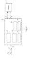
- thermal solar system has a controller 20, a solar collector 1, a heat storage 5, a pump 3, a solar circuit 8 with a line 2 from the solar collector 1 to the heat storage 5 and a return line 7, from the heat storage 5 to the solar collector 1, on and a temperature measuring point 4, which detects a temperature T K , which depends on a temperature of the solar collector 1, and another measuring point 6, which detects a temperature T S , which depends on a temperature of the heat storage location 5.
- Such in Fig. 1 illustrated solar collector system consists of a typically arranged on the roof of a building solar collector 1 and one of the same usually in the basement Building accommodated heat accumulator 5, which are connected to each other via two lines 8, a supply and a return line.
- the heat accumulator 5 and the two lines 8 circulates a fluid heat carrier.
- the solar collector 1 collects the sunlight and heats the heat transfer medium.
- the heat transfer medium transports the heat to the heat accumulator 5, where the domestic or heating water is heated via a heat exchanger (not shown).
- a heat exchanger not shown
- a heat exchanger for example, in the case of a combination storage for solar heating support heating water heated in the store and the service water is heated by a lying in the storage heat exchanger.
- the heat storage ensures that the heat is also available at times when the sun is not shining.
- a pump 3 ensures in the solar circuit for the circulation of the fluid heat carrier and is set in motion when the temperature in the solar collector 1 by a predetermined minimum value is higher than in the heat storage. 5
- the control of the pump is usually by means of a central solar controller 20 as a function of the temperature of the heat carrier in the solar collector 1 and the heat storage 5. To detect these temperatures, the collector temperature is determined at the point 4 of the solar circuit, and at another point 6 the Temperature T S in the heat accumulator 5.
- Fig. 2 schematically shows the structure of a first embodiment of a solar controller 20 for performing the method according to the invention.
- the control device 20 controls the pump power to achieve optimal energy utilization of solar energy.
- the control device 20 for this purpose via an interface 21, the pump 3 on and off, as well as via an interface 22 by means of a pulse width modulation signal (PWM signal) to regulate the pump speed.
- PWM signal pulse width modulation signal
- the invention is not limited to a pump control by pulse width modulation. Usually, other methods known to those skilled in the art, such as wave packet control, may also be used.
- the pump is switched on when the collector temperature T K has exceeded the storage temperature T S by 8 Kelvin, the amount of the so-called switch-on point.
- the pump is switched off when the difference between the tank temperature T S and the collector temperature T K becomes less than 4 Kelvin (switch-off point).
- the values for the switch-on point and the switch-off point can be set specific to the system in order, if necessary, to adapt the operating parameters of the solar system.
- the embodiment of the control device 20 further comprises a means 26 for calculating the differential temperature T KS from the received values T K and T S and a means 23 for performing a first control operation in which the differential temperature T KS to a predetermined first setpoint S KS by controlling a pump speed is controlled.
- the controller is deactivated.
- the direction of action of the controller is negative, ie in the case of positive system deviations (differential temperature T KS ⁇ setpoint S KS ) the pump power is reduced via a corresponding signal via the interface 22, but in the case of negative control deviations it is increased.
- a setpoint S KS of this first control operation is is preset to a value of 10 Kelvin, but can be set as a parameter within a certain range of values.
- the embodiment of the solar controller 20 further includes a means 24 for executing a second control operation, in which S K is defined as in which the collector temperature T K is regulated to a predetermined second set value S K by controlling the pump power, that by increasing the collector temperature T K, the power supply to the heat storage location 5 is reduced.
- S K is defined as in which the collector temperature T K is regulated to a predetermined second set value S K by controlling the pump power, that by increasing the collector temperature T K, the power supply to the heat storage location 5 is reduced.
- S K is defined as in which the collector temperature T K is regulated to a predetermined second set value S K by controlling the pump power, that by increasing the collector temperature T K, the power supply to the heat storage location 5 is reduced.
- S K is defined as in which the collector temperature T K is regulated to a predetermined second set value S K by controlling the pump power, that by increasing the collector temperature T K, the power supply to the heat storage location 5 is reduced.
- the embodiment of the solar controller 20 further has a means that performs other control functions, including monitoring and maintaining the maximum storage temperature and collector maximum temperature.
- Each control function is assigned a priority in the exemplary embodiment.
- Control functions that are assigned a high priority, i. Functions performed at a higher priority compared to low priority functions include collector maximum temperature monitoring, storage and collector corrosion protection, and maximum storage tank temperature monitoring.
- the stagnation time reduction function by means of the second control operation according to the invention has a lower one for this purpose Priority, but a higher priority than the differential temperature control according to the first control operation, so that when a threshold temperature T G is exceeded, can be switched from the first to the second control mode, as will be explained in the following flow chart.
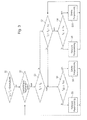
- Fig. 3 schematically shows a flowchart of a first and second control operation and the switching between the first and the second control operation according to the inventive method, as for example by the in Fig. 1 and 2 shown solar system can be performed.
- step S 1 the means 27 checks whether predetermined conditions for switching on the pump 3 are met.
- a collector circuit pump is only switched on when the collector temperature T K has exceeded the storage tank temperature T S by a minimum value E switching point ⁇ . If the collector temperature T K exceeds the storage temperature T S by the set value E switching point, then it is checked in S2 whether a predetermined stop condition for the first control operation is fulfilled. Such a stop condition exists when the pump has been shut down by a higher priority control function, for example when the maximum store temperature has been reached.
- step S3 If the stop condition is not satisfied in step S2, then it is checked in step S3 whether the temperature T S has exceeded a limit temperature T G.
- the default setting for the value T G is set at 55 ° C in a range of 85-95% of the maximum temperature T Smax of the heat storage location 5.
- the maximum temperature T Smax is 60 ° C.
- the limit temperature may also be set in another range far below the maximum storage temperature.
- a second embodiment has a configuration with a temperature T G of 60 ° C at a maximum storage temperature of 90 ° C.
- T G the accumulator is charged to the normal useful temperature "normal” and there is then a very broad temperature range and thus a high energy absorption capacity for stagnation time reduction. This partly makes it possible to completely prevent stagnation.
- a thermostatic mixer is used on the service water side in order to avoid scalding due to excessive hot water temperatures.
- the test step S4 of the first control operation is carried out. In this case, it is checked whether the differential temperature T KS ⁇ the predetermined setpoint temperature difference S KS .
- the value S KS is set to a value in a range of 5 to 20 Kelvin. If the difference temperature is smaller than the setpoint temperature difference, the pump power is reduced as a function of the determined temperature difference in step S5. If the calculated differential temperature T KS is greater than the setpoint temperature difference S KS , the pump speed is increased in step S6. As a result, the solar controller increases the heat transfer to the heat accumulator 5. If the calculated differential temperature T KS is smaller than the setpoint temperature difference S KS , the pump speed is decreased in step S5.
- the solar controller regulates the heat transfer to the heat accumulator 5 and regulates the actual temperature difference T KS on the target difference S KS . Thereafter, a renewed check of the stop condition of the control operation 1 in step S2. As long as the Storage temperature T S remains below the predetermined limit temperature T G , these steps of the first control operation continue to be performed.
- step S7 If the test in step S3 reveals that the temperature T S has exceeded the limit temperature T G , and thus the switchover condition from the first to the second control operation is satisfied, then it is checked in step S7 whether the stop condition of the second control operation is fulfilled.
- a S Preferably, that of A S is set in the range of 5-15% of the maximum temperature T Smax of the heat storage location 5.
- a default setting in the embodiment according to the invention specifies the value 5 K for A S , with a value of 60 ° C for T Smax .
- step S8 If the stop condition of the second control operation checked in step S7 is not met, it is checked in step S8 whether the collector temperature T K is less than or equal to a value S K which represents the setpoint value of the second control operation. If the collector temperature T K is smaller than the value S K , the pump power is reduced in step S9. This reduces the volume flow, thereby increasing the collector temperature T K , and with increasing temperature difference of the collector to the outside temperature deteriorates its efficiency, whereby the energy supply to the heat storage 5 is further reduced. In this way it can be avoided that the storage temperature T S increases up to the maximum storage temperature T Smax , without having to switch off the solar circuit.
- the collector temperature is controlled itself. As long as the collector temperature remains below the predetermined value S K , the means 24 controls the temperature of the collector T K upwards. If a test in step S8 reveals that the temperature T K has reached the setpoint value S K , the pump power is increased. In the second control loop, the collector temperature thus settles to the value S K. Only when the storage temperature has fallen again by a certain amount A S below the limit temperature T G (check in step S7), a change back to the first temperature difference control operation.
- the second set point SK is set by a value A k below a collector maximum temperature T Kmax and at least by the setpoint S KS of the first control operation above the heat storage temperature T S , wherein the value A k is set such that a safety distance from S K to the collector maximum temperature T Kmax is guaranteed.
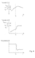
- Fig. 4 shows by way of example the course of the storage tank temperature T S , the collector temperature T K , and the pump power at the time of switching from the first to the second control operation in carrying out the method according to the invention.
- the upper diagram of Fig. 4 is the example of the time course of the storage tank temperature T S shown in the second diagram, the time course of the collector temperature T K , and in the third diagram, the time course of the pump power.
- the heat accumulator 5 has the maximum storage temperature T Smax of 60 ° C, the solar collector 1, the collector maximum temperature T Kmax of 130 ° C.
- the desired differential temperature S KS is 10 Kelvin.
- the storage temperature T S at time t 1 the predetermined limit value T G of 55 ° C, the collector temperature T G is at this time 75 ° C.
- the pump 3 runs at 100% power.
- the solar controller 20 changes from the first temperature difference control mode to the second control mode, since the test in step S3 shows that the storage temperature T S has exceeded the limit temperature.
- step S8 shows that the collector temperature T K (75 °) is less than the second setpoint value S K (115 °). Therefore, in step S9, the pump power is reduced.
- This is in the third diagram of the Fig. 4 Illustrated illustratively, where the pump power drops after the time t 1 to a minimum value of the pump power. As a result, the collector temperature T K increases up to the predetermined desired value S K (115 °). After reaching the set value S K represents the second control mode ensures that the collector temperature T K remains at the value K S.
- the solar collector At the temperature level S K , the solar collector has a much lower efficiency due to the radiation losses, so that the further loading of the memory lasts longer up to its maximum temperature, which in turn delays a shutdown of the solar circuit and thus the stagnation time is reduced.
- the stagnation reduction shown is superior to the known method of the cooling function and the recooling function of the collector, since the heat accumulator 5 is not overloaded above its maximum temperature. Thus, there is no risk of scalding at the tap, an additional function for recooling is not required and the system components are less loaded (no pump on and off).
- Temperature variables which are described with the unit degrees Celsius (° C) (T S , TK, T G, T Smax , TK max , S K ) are to be understood as absolute temperature data ;
- Quantities which are described with the unit Kelvin (K) (S KS , switch-on point, switch-off point, S KS, A S, A K ) define a temperature difference to at least one of the variables T S , T K , T G, T Smax , T K max or S K fixed.
Landscapes
- Engineering & Computer Science (AREA)
- Physics & Mathematics (AREA)
- Thermal Sciences (AREA)
- Chemical & Material Sciences (AREA)
- Combustion & Propulsion (AREA)
- Mechanical Engineering (AREA)
- General Engineering & Computer Science (AREA)
- Life Sciences & Earth Sciences (AREA)
- Sustainable Development (AREA)
- Sustainable Energy (AREA)
- Heat-Pump Type And Storage Water Heaters (AREA)
Applications Claiming Priority (1)
| Application Number | Priority Date | Filing Date | Title |
|---|---|---|---|
| DE102008061130A DE102008061130B4 (de) | 2008-12-09 | 2008-12-09 | Verfahren und Vorrichtung zum Regeln einer thermischen Solaranlage |
Publications (4)
| Publication Number | Publication Date |
|---|---|
| EP2199690A2 true EP2199690A2 (fr) | 2010-06-23 |
| EP2199690A3 EP2199690A3 (fr) | 2016-01-13 |
| EP2199690B1 EP2199690B1 (fr) | 2017-09-06 |
| EP2199690B8 EP2199690B8 (fr) | 2017-11-08 |
Family
ID=41626000
Family Applications (1)
| Application Number | Title | Priority Date | Filing Date |
|---|---|---|---|
| EP09176299.7A Active EP2199690B8 (fr) | 2008-12-09 | 2009-11-18 | Procédé et dispositif destinés au réglage d'une installation solaire thermique |
Country Status (2)
| Country | Link |
|---|---|
| EP (1) | EP2199690B8 (fr) |
| DE (1) | DE102008061130B4 (fr) |
Families Citing this family (1)
| Publication number | Priority date | Publication date | Assignee | Title |
|---|---|---|---|---|
| DE102010007373B4 (de) * | 2010-02-10 | 2016-04-21 | Meibes System-Technik Gmbh | Verfahren und Vorrichtung zum Schutz einer solarthermischen Anlage |
Family Cites Families (5)
| Publication number | Priority date | Publication date | Assignee | Title |
|---|---|---|---|---|
| DE3835012A1 (de) * | 1988-10-14 | 1990-04-19 | Dorfmueller Solaranlagen Gmbh | Verfahren zum steuern einer solaranlage und steuerungsanlage |
| DE19654037C1 (de) * | 1996-12-23 | 1998-07-02 | Solar Diamant Systemtechnik Gm | Anlage zur Gewinnung von Wärme aus Solarenergie |
| DE19707164A1 (de) * | 1997-02-22 | 1998-08-27 | Messer Griesheim Gmbh | Umwälzsystem für Sonnenkollektoren und Heizungsanlagen |
| DE19931787B4 (de) * | 1999-07-08 | 2013-05-08 | Robert Bosch Gmbh | Verfahren zur Regelung einer Solaranlage |
| AT504772B1 (de) * | 2007-01-24 | 2009-04-15 | Vaillant Austria Gmbh | Verfahren zum betrieb einer solarthermischen anlage |
-
2008
- 2008-12-09 DE DE102008061130A patent/DE102008061130B4/de not_active Expired - Fee Related
-
2009
- 2009-11-18 EP EP09176299.7A patent/EP2199690B8/fr active Active
Also Published As
| Publication number | Publication date |
|---|---|
| EP2199690B1 (fr) | 2017-09-06 |
| EP2199690A3 (fr) | 2016-01-13 |
| DE102008061130B4 (de) | 2012-02-16 |
| DE102008061130A1 (de) | 2010-06-10 |
| EP2199690B8 (fr) | 2017-11-08 |
Similar Documents
| Publication | Publication Date | Title |
|---|---|---|
| DE3109843C1 (de) | Heizungsanlage mit einem Heizkessel und einer Waermepumpe | |
| DE102014103668A1 (de) | Verfahren zum Betrieb einer Heiz- und/oder Kühlanlage | |
| EP3722680B1 (fr) | Procédé de réalisation d'une comparaison hydraulique d'un système de chauffage pour un bâtiment ainsi que système de chauffage conçu pour celui-ci | |
| EP3059652B1 (fr) | Dispositif de commande et installation de regulation de temperature ambiante | |
| DE102014014325A1 (de) | Wärmepumpenvorrichtung und Verfahren zum Steuern einer Wärmepumpenvorrichtung | |
| DE2843929B2 (de) | Anordnung zur Steuerung der Raumtemperatur | |
| DE202012012915U1 (de) | Heiz- und/oder Kühlanlage | |
| EP2199690B1 (fr) | Procédé et dispositif destinés au réglage d'une installation solaire thermique | |
| EP0444403B1 (fr) | Méthode pour contrôler une installation de capteurs solaires | |
| DE102008004863A1 (de) | Verfahren zum Betrieb einer solarthermischen Anlage | |
| EP3740718B1 (fr) | Procédé de régulation d'une pompe de circulation, pompe de circulation et installation de chauffage | |
| EP1764563B1 (fr) | Régulateur solaire et méthode pour régler une installation de collecteurs solaires | |
| EP3779286A1 (fr) | Procédé de fonctionnement d'une installation de chauffage | |
| AT526937B1 (de) | Verfahren, Vorrichtung und System für eine Kontrolle eines Aufheizvorgangs eines Brennstoffzellensystems | |
| EP2369245A1 (fr) | Procédé de réglage d'une valeur de consigne de température d'entrée d'une courbe de chauffe d'un système de chauffage | |
| EP2301100B1 (fr) | Procédé de régulation de température dans un système de piles à combustible et système de piles à combustible | |
| DE102010056301A1 (de) | Verfahren zur automatischen Optimierung eines Heizsystems sowie Heizsystem | |
| DE102022121873B3 (de) | Thermisches Koppelmodul, thermisches Koppelungssystem und Verfahren zur Wärmeübertragung zwischen mindestens einem elektrischen Energiespeicher und mindestens einem Wärmeabnehmer | |
| EP2218967A2 (fr) | Procédé et dispositif de réglage de la durée de fonctionnement d'un brûleur | |
| EP3971484B1 (fr) | Procédé de production d'eau chaude dans un bâtiment, installation de production d'eau chaude et dispositif de commande d'une installation de production d'eau chaude | |
| EP2655979B1 (fr) | Procédé de régulation d'un générateur de chaleur d'un système de chauffage et système de chauffage | |
| DE2711601A1 (de) | Einrichtung zum regeln einer umlaufwasser-heizungsanlage | |
| DE2711624A1 (de) | Heizungsanlage mit einem sonnenkollektor | |
| EP1594025A2 (fr) | Procédé et appareil de chauffage pour réguler une température | |
| EP2679927A2 (fr) | Installation de chauffage doté d'un accumulateur-tampon thermique |
Legal Events
| Date | Code | Title | Description |
|---|---|---|---|
| PUAI | Public reference made under article 153(3) epc to a published international application that has entered the european phase |
Free format text: ORIGINAL CODE: 0009012 |
|
| AK | Designated contracting states |
Kind code of ref document: A2 Designated state(s): AT BE BG CH CY CZ DE DK EE ES FI FR GB GR HR HU IE IS IT LI LT LU LV MC MK MT NL NO PL PT RO SE SI SK SM TR |
|
| AX | Request for extension of the european patent |
Extension state: AL BA RS |
|
| PUAL | Search report despatched |
Free format text: ORIGINAL CODE: 0009013 |
|
| AK | Designated contracting states |
Kind code of ref document: A3 Designated state(s): AT BE BG CH CY CZ DE DK EE ES FI FR GB GR HR HU IE IS IT LI LT LU LV MC MK MT NL NO PL PT RO SE SI SK SM TR |
|
| AX | Request for extension of the european patent |
Extension state: AL BA RS |
|
| RIC1 | Information provided on ipc code assigned before grant |
Ipc: F24D 11/00 20060101AFI20151207BHEP Ipc: F24D 19/10 20060101ALI20151207BHEP |
|
| 17P | Request for examination filed |
Effective date: 20160713 |
|
| GRAP | Despatch of communication of intention to grant a patent |
Free format text: ORIGINAL CODE: EPIDOSNIGR1 |
|
| STAA | Information on the status of an ep patent application or granted ep patent |
Free format text: STATUS: GRANT OF PATENT IS INTENDED |
|
| INTG | Intention to grant announced |
Effective date: 20170221 |
|
| GRAS | Grant fee paid |
Free format text: ORIGINAL CODE: EPIDOSNIGR3 |
|
| GRAA | (expected) grant |
Free format text: ORIGINAL CODE: 0009210 |
|
| STAA | Information on the status of an ep patent application or granted ep patent |
Free format text: STATUS: THE PATENT HAS BEEN GRANTED |
|
| AK | Designated contracting states |
Kind code of ref document: B1 Designated state(s): AT BE BG CH CY CZ DE DK EE ES FI FR GB GR HR HU IE IS IT LI LT LU LV MC MK MT NL NO PL PT RO SE SI SK SM TR |
|
| REG | Reference to a national code |
Ref country code: GB Ref legal event code: FG4D Free format text: NOT ENGLISH |
|
| REG | Reference to a national code |
Ref country code: CH Ref legal event code: EP Ref country code: AT Ref legal event code: REF Ref document number: 926307 Country of ref document: AT Kind code of ref document: T Effective date: 20170915 |
|
| GRAT | Correction requested after decision to grant or after decision to maintain patent in amended form |
Free format text: ORIGINAL CODE: EPIDOSNCDEC |
|
| REG | Reference to a national code |
Ref country code: IE Ref legal event code: FG4D Free format text: LANGUAGE OF EP DOCUMENT: GERMAN |
|
| REG | Reference to a national code |
Ref country code: DE Ref legal event code: R096 Ref document number: 502009014324 Country of ref document: DE |
|
| RAP2 | Party data changed (patent owner data changed or rights of a patent transferred) |
Owner name: VIESSMANN WERKE GMBH & CO. KG |
|
| REG | Reference to a national code |
Ref country code: FR Ref legal event code: PLFP Year of fee payment: 9 |
|
| REG | Reference to a national code |
Ref country code: NL Ref legal event code: MP Effective date: 20170906 |
|
| REG | Reference to a national code |
Ref country code: LT Ref legal event code: MG4D |
|
| PG25 | Lapsed in a contracting state [announced via postgrant information from national office to epo] |
Ref country code: HR Free format text: LAPSE BECAUSE OF FAILURE TO SUBMIT A TRANSLATION OF THE DESCRIPTION OR TO PAY THE FEE WITHIN THE PRESCRIBED TIME-LIMIT Effective date: 20170906 Ref country code: NO Free format text: LAPSE BECAUSE OF FAILURE TO SUBMIT A TRANSLATION OF THE DESCRIPTION OR TO PAY THE FEE WITHIN THE PRESCRIBED TIME-LIMIT Effective date: 20171206 Ref country code: LT Free format text: LAPSE BECAUSE OF FAILURE TO SUBMIT A TRANSLATION OF THE DESCRIPTION OR TO PAY THE FEE WITHIN THE PRESCRIBED TIME-LIMIT Effective date: 20170906 Ref country code: FI Free format text: LAPSE BECAUSE OF FAILURE TO SUBMIT A TRANSLATION OF THE DESCRIPTION OR TO PAY THE FEE WITHIN THE PRESCRIBED TIME-LIMIT Effective date: 20170906 Ref country code: SE Free format text: LAPSE BECAUSE OF FAILURE TO SUBMIT A TRANSLATION OF THE DESCRIPTION OR TO PAY THE FEE WITHIN THE PRESCRIBED TIME-LIMIT Effective date: 20170906 |
|
| PG25 | Lapsed in a contracting state [announced via postgrant information from national office to epo] |
Ref country code: BG Free format text: LAPSE BECAUSE OF FAILURE TO SUBMIT A TRANSLATION OF THE DESCRIPTION OR TO PAY THE FEE WITHIN THE PRESCRIBED TIME-LIMIT Effective date: 20171206 Ref country code: ES Free format text: LAPSE BECAUSE OF FAILURE TO SUBMIT A TRANSLATION OF THE DESCRIPTION OR TO PAY THE FEE WITHIN THE PRESCRIBED TIME-LIMIT Effective date: 20170906 Ref country code: GR Free format text: LAPSE BECAUSE OF FAILURE TO SUBMIT A TRANSLATION OF THE DESCRIPTION OR TO PAY THE FEE WITHIN THE PRESCRIBED TIME-LIMIT Effective date: 20171207 Ref country code: LV Free format text: LAPSE BECAUSE OF FAILURE TO SUBMIT A TRANSLATION OF THE DESCRIPTION OR TO PAY THE FEE WITHIN THE PRESCRIBED TIME-LIMIT Effective date: 20170906 |
|
| PG25 | Lapsed in a contracting state [announced via postgrant information from national office to epo] |
Ref country code: NL Free format text: LAPSE BECAUSE OF FAILURE TO SUBMIT A TRANSLATION OF THE DESCRIPTION OR TO PAY THE FEE WITHIN THE PRESCRIBED TIME-LIMIT Effective date: 20170906 |
|
| PG25 | Lapsed in a contracting state [announced via postgrant information from national office to epo] |
Ref country code: CZ Free format text: LAPSE BECAUSE OF FAILURE TO SUBMIT A TRANSLATION OF THE DESCRIPTION OR TO PAY THE FEE WITHIN THE PRESCRIBED TIME-LIMIT Effective date: 20170906 Ref country code: RO Free format text: LAPSE BECAUSE OF FAILURE TO SUBMIT A TRANSLATION OF THE DESCRIPTION OR TO PAY THE FEE WITHIN THE PRESCRIBED TIME-LIMIT Effective date: 20170906 Ref country code: PL Free format text: LAPSE BECAUSE OF FAILURE TO SUBMIT A TRANSLATION OF THE DESCRIPTION OR TO PAY THE FEE WITHIN THE PRESCRIBED TIME-LIMIT Effective date: 20170906 |
|
| PG25 | Lapsed in a contracting state [announced via postgrant information from national office to epo] |
Ref country code: EE Free format text: LAPSE BECAUSE OF FAILURE TO SUBMIT A TRANSLATION OF THE DESCRIPTION OR TO PAY THE FEE WITHIN THE PRESCRIBED TIME-LIMIT Effective date: 20170906 Ref country code: SK Free format text: LAPSE BECAUSE OF FAILURE TO SUBMIT A TRANSLATION OF THE DESCRIPTION OR TO PAY THE FEE WITHIN THE PRESCRIBED TIME-LIMIT Effective date: 20170906 Ref country code: IS Free format text: LAPSE BECAUSE OF FAILURE TO SUBMIT A TRANSLATION OF THE DESCRIPTION OR TO PAY THE FEE WITHIN THE PRESCRIBED TIME-LIMIT Effective date: 20180106 Ref country code: SM Free format text: LAPSE BECAUSE OF FAILURE TO SUBMIT A TRANSLATION OF THE DESCRIPTION OR TO PAY THE FEE WITHIN THE PRESCRIBED TIME-LIMIT Effective date: 20170906 |
|
| REG | Reference to a national code |
Ref country code: DE Ref legal event code: R097 Ref document number: 502009014324 Country of ref document: DE |
|
| PG25 | Lapsed in a contracting state [announced via postgrant information from national office to epo] |
Ref country code: MC Free format text: LAPSE BECAUSE OF FAILURE TO SUBMIT A TRANSLATION OF THE DESCRIPTION OR TO PAY THE FEE WITHIN THE PRESCRIBED TIME-LIMIT Effective date: 20170906 |
|
| PLBE | No opposition filed within time limit |
Free format text: ORIGINAL CODE: 0009261 |
|
| STAA | Information on the status of an ep patent application or granted ep patent |
Free format text: STATUS: NO OPPOSITION FILED WITHIN TIME LIMIT |
|
| PG25 | Lapsed in a contracting state [announced via postgrant information from national office to epo] |
Ref country code: CH Free format text: LAPSE BECAUSE OF NON-PAYMENT OF DUE FEES Effective date: 20171130 Ref country code: DK Free format text: LAPSE BECAUSE OF FAILURE TO SUBMIT A TRANSLATION OF THE DESCRIPTION OR TO PAY THE FEE WITHIN THE PRESCRIBED TIME-LIMIT Effective date: 20170906 Ref country code: LI Free format text: LAPSE BECAUSE OF NON-PAYMENT OF DUE FEES Effective date: 20171130 |
|
| 26N | No opposition filed |
Effective date: 20180607 |
|
| GBPC | Gb: european patent ceased through non-payment of renewal fee |
Effective date: 20171206 |
|
| PG25 | Lapsed in a contracting state [announced via postgrant information from national office to epo] |
Ref country code: SI Free format text: LAPSE BECAUSE OF FAILURE TO SUBMIT A TRANSLATION OF THE DESCRIPTION OR TO PAY THE FEE WITHIN THE PRESCRIBED TIME-LIMIT Effective date: 20170906 |
|
| REG | Reference to a national code |
Ref country code: IE Ref legal event code: MM4A |
|
| PG25 | Lapsed in a contracting state [announced via postgrant information from national office to epo] |
Ref country code: MT Free format text: LAPSE BECAUSE OF FAILURE TO SUBMIT A TRANSLATION OF THE DESCRIPTION OR TO PAY THE FEE WITHIN THE PRESCRIBED TIME-LIMIT Effective date: 20170906 |
|
| PG25 | Lapsed in a contracting state [announced via postgrant information from national office to epo] |
Ref country code: IE Free format text: LAPSE BECAUSE OF NON-PAYMENT OF DUE FEES Effective date: 20171118 |
|
| PG25 | Lapsed in a contracting state [announced via postgrant information from national office to epo] |
Ref country code: GB Free format text: LAPSE BECAUSE OF NON-PAYMENT OF DUE FEES Effective date: 20171206 |
|
| PG25 | Lapsed in a contracting state [announced via postgrant information from national office to epo] |
Ref country code: HU Free format text: LAPSE BECAUSE OF FAILURE TO SUBMIT A TRANSLATION OF THE DESCRIPTION OR TO PAY THE FEE WITHIN THE PRESCRIBED TIME-LIMIT; INVALID AB INITIO Effective date: 20091118 |
|
| PG25 | Lapsed in a contracting state [announced via postgrant information from national office to epo] |
Ref country code: CY Free format text: LAPSE BECAUSE OF NON-PAYMENT OF DUE FEES Effective date: 20170906 |
|
| PG25 | Lapsed in a contracting state [announced via postgrant information from national office to epo] |
Ref country code: MK Free format text: LAPSE BECAUSE OF FAILURE TO SUBMIT A TRANSLATION OF THE DESCRIPTION OR TO PAY THE FEE WITHIN THE PRESCRIBED TIME-LIMIT Effective date: 20170906 |
|
| PG25 | Lapsed in a contracting state [announced via postgrant information from national office to epo] |
Ref country code: TR Free format text: LAPSE BECAUSE OF FAILURE TO SUBMIT A TRANSLATION OF THE DESCRIPTION OR TO PAY THE FEE WITHIN THE PRESCRIBED TIME-LIMIT Effective date: 20170906 |
|
| PG25 | Lapsed in a contracting state [announced via postgrant information from national office to epo] |
Ref country code: PT Free format text: LAPSE BECAUSE OF FAILURE TO SUBMIT A TRANSLATION OF THE DESCRIPTION OR TO PAY THE FEE WITHIN THE PRESCRIBED TIME-LIMIT Effective date: 20170906 |
|
| P01 | Opt-out of the competence of the unified patent court (upc) registered |
Effective date: 20230515 |
|
| PGFP | Annual fee paid to national office [announced via postgrant information from national office to epo] |
Ref country code: LU Payment date: 20231120 Year of fee payment: 15 |
|
| PGFP | Annual fee paid to national office [announced via postgrant information from national office to epo] |
Ref country code: IT Payment date: 20231130 Year of fee payment: 15 Ref country code: AT Payment date: 20231117 Year of fee payment: 15 |
|
| PGFP | Annual fee paid to national office [announced via postgrant information from national office to epo] |
Ref country code: BE Payment date: 20231121 Year of fee payment: 15 |
|
| PGFP | Annual fee paid to national office [announced via postgrant information from national office to epo] |
Ref country code: DE Payment date: 20241130 Year of fee payment: 16 |
|
| REG | Reference to a national code |
Ref country code: DE Ref legal event code: R081 Ref document number: 502009014324 Country of ref document: DE Owner name: VIESSMANN HOLDING INTERNATIONAL GMBH, DE Free format text: FORMER OWNER: VIESSMANN WERKE GMBH & CO KG, 35108 ALLENDORF, DE |
|
| PG25 | Lapsed in a contracting state [announced via postgrant information from national office to epo] |
Ref country code: LU Free format text: LAPSE BECAUSE OF NON-PAYMENT OF DUE FEES Effective date: 20241118 |
|
| REG | Reference to a national code |
Ref country code: AT Ref legal event code: MM01 Ref document number: 926307 Country of ref document: AT Kind code of ref document: T Effective date: 20241118 |
|
| PG25 | Lapsed in a contracting state [announced via postgrant information from national office to epo] |
Ref country code: AT Free format text: LAPSE BECAUSE OF NON-PAYMENT OF DUE FEES Effective date: 20241118 |
|
| REG | Reference to a national code |
Ref country code: BE Ref legal event code: MM Effective date: 20241130 |
|
| PG25 | Lapsed in a contracting state [announced via postgrant information from national office to epo] |
Ref country code: IT Free format text: LAPSE BECAUSE OF NON-PAYMENT OF DUE FEES Effective date: 20241118 |
|
| PG25 | Lapsed in a contracting state [announced via postgrant information from national office to epo] |
Ref country code: BE Free format text: LAPSE BECAUSE OF NON-PAYMENT OF DUE FEES Effective date: 20241130 |
|
| PGFP | Annual fee paid to national office [announced via postgrant information from national office to epo] |
Ref country code: FR Payment date: 20251023 Year of fee payment: 17 |