EP2199554A1 - Exhaust gas purifier - Google Patents
Exhaust gas purifier Download PDFInfo
- Publication number
- EP2199554A1 EP2199554A1 EP08751954A EP08751954A EP2199554A1 EP 2199554 A1 EP2199554 A1 EP 2199554A1 EP 08751954 A EP08751954 A EP 08751954A EP 08751954 A EP08751954 A EP 08751954A EP 2199554 A1 EP2199554 A1 EP 2199554A1
- Authority
- EP
- European Patent Office
- Prior art keywords
- exhaust gas
- housing
- catalytic converter
- communicating pipe
- purification apparatus
- Prior art date
- Legal status (The legal status is an assumption and is not a legal conclusion. Google has not performed a legal analysis and makes no representation as to the accuracy of the status listed.)
- Granted
Links
Images


Classifications
-
- F—MECHANICAL ENGINEERING; LIGHTING; HEATING; WEAPONS; BLASTING
- F01—MACHINES OR ENGINES IN GENERAL; ENGINE PLANTS IN GENERAL; STEAM ENGINES
- F01N—GAS-FLOW SILENCERS OR EXHAUST APPARATUS FOR MACHINES OR ENGINES IN GENERAL; GAS-FLOW SILENCERS OR EXHAUST APPARATUS FOR INTERNAL-COMBUSTION ENGINES
- F01N3/00—Exhaust or silencing apparatus having means for purifying, rendering innocuous, or otherwise treating exhaust
- F01N3/02—Exhaust or silencing apparatus having means for purifying, rendering innocuous, or otherwise treating exhaust for cooling, or for removing solid constituents of, exhaust
- F01N3/021—Exhaust or silencing apparatus having means for purifying, rendering innocuous, or otherwise treating exhaust for cooling, or for removing solid constituents of, exhaust by means of filters
- F01N3/033—Exhaust or silencing apparatus having means for purifying, rendering innocuous, or otherwise treating exhaust for cooling, or for removing solid constituents of, exhaust by means of filters in combination with other devices
- F01N3/035—Exhaust or silencing apparatus having means for purifying, rendering innocuous, or otherwise treating exhaust for cooling, or for removing solid constituents of, exhaust by means of filters in combination with other devices with catalytic reactors
-
- F—MECHANICAL ENGINEERING; LIGHTING; HEATING; WEAPONS; BLASTING
- F01—MACHINES OR ENGINES IN GENERAL; ENGINE PLANTS IN GENERAL; STEAM ENGINES
- F01N—GAS-FLOW SILENCERS OR EXHAUST APPARATUS FOR MACHINES OR ENGINES IN GENERAL; GAS-FLOW SILENCERS OR EXHAUST APPARATUS FOR INTERNAL-COMBUSTION ENGINES
- F01N13/00—Exhaust or silencing apparatus characterised by constructional features
- F01N13/009—Exhaust or silencing apparatus characterised by constructional features having two or more separate purifying devices arranged in series
- F01N13/0097—Exhaust or silencing apparatus characterised by constructional features having two or more separate purifying devices arranged in series the purifying devices are arranged in a single housing
-
- F—MECHANICAL ENGINEERING; LIGHTING; HEATING; WEAPONS; BLASTING
- F01—MACHINES OR ENGINES IN GENERAL; ENGINE PLANTS IN GENERAL; STEAM ENGINES
- F01N—GAS-FLOW SILENCERS OR EXHAUST APPARATUS FOR MACHINES OR ENGINES IN GENERAL; GAS-FLOW SILENCERS OR EXHAUST APPARATUS FOR INTERNAL-COMBUSTION ENGINES
- F01N3/00—Exhaust or silencing apparatus having means for purifying, rendering innocuous, or otherwise treating exhaust
- F01N3/08—Exhaust or silencing apparatus having means for purifying, rendering innocuous, or otherwise treating exhaust for rendering innocuous
- F01N3/10—Exhaust or silencing apparatus having means for purifying, rendering innocuous, or otherwise treating exhaust for rendering innocuous by thermal or catalytic conversion of noxious components of exhaust
- F01N3/105—General auxiliary catalysts, e.g. upstream or downstream of the main catalyst
- F01N3/106—Auxiliary oxidation catalysts
-
- F—MECHANICAL ENGINEERING; LIGHTING; HEATING; WEAPONS; BLASTING
- F01—MACHINES OR ENGINES IN GENERAL; ENGINE PLANTS IN GENERAL; STEAM ENGINES
- F01N—GAS-FLOW SILENCERS OR EXHAUST APPARATUS FOR MACHINES OR ENGINES IN GENERAL; GAS-FLOW SILENCERS OR EXHAUST APPARATUS FOR INTERNAL-COMBUSTION ENGINES
- F01N3/00—Exhaust or silencing apparatus having means for purifying, rendering innocuous, or otherwise treating exhaust
- F01N3/08—Exhaust or silencing apparatus having means for purifying, rendering innocuous, or otherwise treating exhaust for rendering innocuous
- F01N3/10—Exhaust or silencing apparatus having means for purifying, rendering innocuous, or otherwise treating exhaust for rendering innocuous by thermal or catalytic conversion of noxious components of exhaust
- F01N3/18—Exhaust or silencing apparatus having means for purifying, rendering innocuous, or otherwise treating exhaust for rendering innocuous by thermal or catalytic conversion of noxious components of exhaust characterised by methods of operation; Control
- F01N3/20—Exhaust or silencing apparatus having means for purifying, rendering innocuous, or otherwise treating exhaust for rendering innocuous by thermal or catalytic conversion of noxious components of exhaust characterised by methods of operation; Control specially adapted for catalytic conversion
- F01N3/206—Adding periodically or continuously substances to exhaust gases for promoting purification, e.g. catalytic material in liquid form, NOx reducing agents
- F01N3/2066—Selective catalytic reduction [SCR]
-
- F—MECHANICAL ENGINEERING; LIGHTING; HEATING; WEAPONS; BLASTING
- F01—MACHINES OR ENGINES IN GENERAL; ENGINE PLANTS IN GENERAL; STEAM ENGINES
- F01N—GAS-FLOW SILENCERS OR EXHAUST APPARATUS FOR MACHINES OR ENGINES IN GENERAL; GAS-FLOW SILENCERS OR EXHAUST APPARATUS FOR INTERNAL-COMBUSTION ENGINES
- F01N3/00—Exhaust or silencing apparatus having means for purifying, rendering innocuous, or otherwise treating exhaust
- F01N3/08—Exhaust or silencing apparatus having means for purifying, rendering innocuous, or otherwise treating exhaust for rendering innocuous
- F01N3/10—Exhaust or silencing apparatus having means for purifying, rendering innocuous, or otherwise treating exhaust for rendering innocuous by thermal or catalytic conversion of noxious components of exhaust
- F01N3/24—Exhaust or silencing apparatus having means for purifying, rendering innocuous, or otherwise treating exhaust for rendering innocuous by thermal or catalytic conversion of noxious components of exhaust characterised by constructional aspects of converting apparatus
- F01N3/28—Construction of catalytic reactors
-
- B—PERFORMING OPERATIONS; TRANSPORTING
- B01—PHYSICAL OR CHEMICAL PROCESSES OR APPARATUS IN GENERAL
- B01D—SEPARATION
- B01D2251/00—Reactants
- B01D2251/20—Reductants
- B01D2251/206—Ammonium compounds
-
- B—PERFORMING OPERATIONS; TRANSPORTING
- B01—PHYSICAL OR CHEMICAL PROCESSES OR APPARATUS IN GENERAL
- B01D—SEPARATION
- B01D2251/00—Reactants
- B01D2251/20—Reductants
- B01D2251/208—Hydrocarbons
-
- B—PERFORMING OPERATIONS; TRANSPORTING
- B01—PHYSICAL OR CHEMICAL PROCESSES OR APPARATUS IN GENERAL
- B01D—SEPARATION
- B01D2258/00—Sources of waste gases
- B01D2258/01—Engine exhaust gases
- B01D2258/012—Diesel engines and lean burn gasoline engines
-
- B—PERFORMING OPERATIONS; TRANSPORTING
- B01—PHYSICAL OR CHEMICAL PROCESSES OR APPARATUS IN GENERAL
- B01D—SEPARATION
- B01D53/00—Separation of gases or vapours; Recovering vapours of volatile solvents from gases; Chemical or biological purification of waste gases, e.g. engine exhaust gases, smoke, fumes, flue gases, aerosols
- B01D53/34—Chemical or biological purification of waste gases
- B01D53/92—Chemical or biological purification of waste gases of engine exhaust gases
- B01D53/94—Chemical or biological purification of waste gases of engine exhaust gases by catalytic processes
- B01D53/9404—Removing only nitrogen compounds
- B01D53/9409—Nitrogen oxides
- B01D53/9413—Processes characterised by a specific catalyst
- B01D53/9418—Processes characterised by a specific catalyst for removing nitrogen oxides by selective catalytic reduction [SCR] using a reducing agent in a lean exhaust gas
-
- B—PERFORMING OPERATIONS; TRANSPORTING
- B01—PHYSICAL OR CHEMICAL PROCESSES OR APPARATUS IN GENERAL
- B01D—SEPARATION
- B01D53/00—Separation of gases or vapours; Recovering vapours of volatile solvents from gases; Chemical or biological purification of waste gases, e.g. engine exhaust gases, smoke, fumes, flue gases, aerosols
- B01D53/34—Chemical or biological purification of waste gases
- B01D53/92—Chemical or biological purification of waste gases of engine exhaust gases
- B01D53/94—Chemical or biological purification of waste gases of engine exhaust gases by catalytic processes
- B01D53/944—Simultaneously removing carbon monoxide, hydrocarbons or carbon making use of oxidation catalysts
-
- B—PERFORMING OPERATIONS; TRANSPORTING
- B01—PHYSICAL OR CHEMICAL PROCESSES OR APPARATUS IN GENERAL
- B01D—SEPARATION
- B01D53/00—Separation of gases or vapours; Recovering vapours of volatile solvents from gases; Chemical or biological purification of waste gases, e.g. engine exhaust gases, smoke, fumes, flue gases, aerosols
- B01D53/34—Chemical or biological purification of waste gases
- B01D53/92—Chemical or biological purification of waste gases of engine exhaust gases
- B01D53/94—Chemical or biological purification of waste gases of engine exhaust gases by catalytic processes
- B01D53/9459—Removing one or more of nitrogen oxides, carbon monoxide, or hydrocarbons by multiple successive catalytic functions; systems with more than one different function, e.g. zone coated catalysts
- B01D53/9463—Removing one or more of nitrogen oxides, carbon monoxide, or hydrocarbons by multiple successive catalytic functions; systems with more than one different function, e.g. zone coated catalysts with catalysts positioned on one brick
- B01D53/9472—Removing one or more of nitrogen oxides, carbon monoxide, or hydrocarbons by multiple successive catalytic functions; systems with more than one different function, e.g. zone coated catalysts with catalysts positioned on one brick in different zones
-
- F—MECHANICAL ENGINEERING; LIGHTING; HEATING; WEAPONS; BLASTING
- F01—MACHINES OR ENGINES IN GENERAL; ENGINE PLANTS IN GENERAL; STEAM ENGINES
- F01N—GAS-FLOW SILENCERS OR EXHAUST APPARATUS FOR MACHINES OR ENGINES IN GENERAL; GAS-FLOW SILENCERS OR EXHAUST APPARATUS FOR INTERNAL-COMBUSTION ENGINES
- F01N2610/00—Adding substances to exhaust gases
- F01N2610/02—Adding substances to exhaust gases the substance being ammonia or urea
-
- Y—GENERAL TAGGING OF NEW TECHNOLOGICAL DEVELOPMENTS; GENERAL TAGGING OF CROSS-SECTIONAL TECHNOLOGIES SPANNING OVER SEVERAL SECTIONS OF THE IPC; TECHNICAL SUBJECTS COVERED BY FORMER USPC CROSS-REFERENCE ART COLLECTIONS [XRACs] AND DIGESTS
- Y02—TECHNOLOGIES OR APPLICATIONS FOR MITIGATION OR ADAPTATION AGAINST CLIMATE CHANGE
- Y02T—CLIMATE CHANGE MITIGATION TECHNOLOGIES RELATED TO TRANSPORTATION
- Y02T10/00—Road transport of goods or passengers
- Y02T10/10—Internal combustion engine [ICE] based vehicles
- Y02T10/12—Improving ICE efficiencies
Definitions
- the present invention relates to an exhaust gas purification apparatus for an engine, particularly to an SCR (Selective Catalytic Reduction) type exhaust gas purification apparatus including a Particulate Matter (PM) collection filter.
- SCR Selective Catalytic Reduction
- PM Particulate Matter
- the SCR type exhaust gas purification apparatus is proposed as the exhaust gas purification apparatus that removes nitrogen oxide (NOx) contained in the exhaust gas of the engine.
- a reducing catalytic converter included in the exhaust gas purification apparatus is provided in an exhaust gas system, and a reducing agent is injected from a nozzle to the exhaust gas on an upstream side of the reducing catalytic converter, to subject a catalytic reduction reaction of NOx in the exhaust gas and the reducing agent to thereby perform a purification treatment of NOx to a harmless component.
- a urea aqueous solution, an ammonia aqueous solution, or an HC liquid reducing agent (referred to as liquid reducing agent while a precursor thereof is included) is adopted as the reducing agent.
- the urea aqueous solution and the ammonia aqueous solution are hydrolyzed with exhaust gas heat and water vapor in the exhaust gas to easily generate ammonia.
- the SCR type exhaust gas purification apparatus having the PM collecting function in addition to the NOx removing function is also achieved in accordance with tightening of emission gas regulation.
- Patent literature 1 there has been proposed an exhaust gas purification apparatus described in Japanese Laid-Open (kokai) Patent Application Publication No. 2007-040224 (Patent literature 1).
- the exhaust gas purification apparatus disclosed in Patent literature 1 includes a first housing in which an oxidation catalytic converter for oxidizing nitrogen monoxide in exhaust gas and the PM collecting filter are contained, and a second housing in which the reducing catalytic converter and an ammonia oxidation catalytic converter for oxidizing excess ammonia are contained, in which the nozzle that injects the liquid reducing agent is provided in a pipe that connects the first housing and the second housing.
- the first housing and the second housing are disposed while sandwiching a chassis frame therebetween (that is, the first housing and the second housing are transversely disposed), which allows for compact layout of the exhaust gas purification apparatus in a front-back direction of a vehicle (paragraph [0006], [0007], and [0009] of Patent literature 1).
- Patent Literature 1 Japanese Laid-Open (kokai) Patent Application Publication No. 2007-040224
- the invention proposes an exhaust gas purification apparatus in which the restriction of the layout is lessened to be able to further achieve the space-saving.
- An exhaust gas purification apparatus proposed herein in order to solve the problem mentioned above, includes: a first cylindrical housing in which at least a filter for collecting a particulate matter in exhaust gas is contained; a second cylindrical housing in which at least a reducing catalytic converter for reduction-purifying nitrogen oxide with a liquid reducing agent is contained; a communicating pipe that connects between far end portions of the each housing; and a nozzle that is disposed in the communicating pipe and injects liquid reducing agent into the exhaust gas, in which: the first and second cylindrical housings are closely disposed such that axis lines thereof are arranged substantially parallel to each other; and the communicating pipe is disposed such that an axis line thereof is arranged substantially parallel with the axis lines of the housings, thereby folding a flow passage of the exhaust gas from the first housing to the second housing.
- the first housing may contain an oxidation catalytic converter that oxidizes nitrogen monoxide in the exhaust gas to nitrogen dioxide on the upstream side of the PM collection filter.
- the second housing may contain an ammonia oxidation catalytic converter that oxidizes ammonia in the exhaust gas on the downstream side of the reducing catalytic converter.
- the far end portions (that is, end portions located on the opposite sides away from each other) of the two cylindrical housings disposed in parallel are connected through the communicating pipe, which allows the long length of the communicating pipe to be secured. Accordingly, the pipe length enough to evenly diffuse the liquid reducing agent can be obtained when the nozzle for the liquid reducing agent is disposed at an end of the communicating pipe.
- the flow passage of the exhaust gas is folded by the structure in which the two cylindrical housings are disposed in parallel while the communicating pipe that connects the far end portions of the two cylindrical housings is disposed. Therefore, the size can be reduced in the length direction from the upstream to the downstream of the exhaust gas flow, and it is unnecessary to make the layout of the pipe that strides across the chassis frame as is conventionally done.
- the compact size equivalent to a square muffler in which the communicating pipe is accommodated in the silhouette (projection area) of two substantially parallel housings can be achieved while the length enough to evenly diffuse the liquid reducing agent is obtained in the communicating pipe, and the space-saving can be achieved without imposing the conventional layout restriction.
- FIGS. 1 to 3 illustrate an embodiment of an exhaust gas purification apparatus.
- This exhaust gas purification apparatus is provided in, for example, an exhaust gas system of a diesel engine, and the exhaust gas purification apparatus includes both the SCR and the PM collection filter as described above.
- the exhaust gas purification apparatus includes a first cylindrical housing 10, a second cylindrical housing 20, and a communicating pipe 30 that connects between far end portions of the housings 10 and 20.
- the first housing 10 and the second housing 20 are closely disposed such that an axis line 10a and an axis line 20a thereof are arranged substantially parallel to each other (a parallel level to the sight).
- the communicating pipe 30 is disposed such that an axis line 30a thereof is arranged substantially parallel with the axis lines 10a and 20a of the housings 10 and 20 (a parallel level to the sight).
- an inflow port 11 is formed in an end portion on an upstream side of the exhaust gas flow, and a discharge port 12 is formed in an end portion on a downstream side of the exhaust gas flow.
- the inflow port 11 is formed in an end face in the upstream side end portion
- the discharge port 12 is formed in a side face in the downstream side end portion.
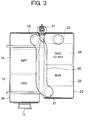
- An oxidation catalytic converter 13 and a filter 14 are contained in series between the inflow port 11 and the discharge port 12. The oxidation catalytic converter 13 oxidizes nitrogen monoxide in the exhaust gas to nitrogen dioxide, the filter 14 collects PM in the exhaust gas, and the oxidation catalytic converter 13 is located on the upstream side of the filter 14 ( FIG. 3 ).
- an inflow port 21 is formed in an end portion on an upstream side of the exhaust gas flow, and a discharge port 22 is formed in an end portion on a downstream side of the exhaust gas flow.
- both the inflow port 21 and the discharge port 22 are formed in side faces in the upstream and downstream end portions.
- a reducing catalytic converter 23 and an ammonia oxidation catalytic converter 24 are contained in series between the inflow port 21 and the discharge port 22.
- the reducing catalytic converter 23 reduction-purifies nitrogen oxide with liquid reducing agent, the ammonia oxidation catalytic converter 24 oxidizes ammonia in the exhaust gas, and the reducing catalytic converter 23 is located on the upstream side of the ammonia oxidation catalytic converter 24 ( FIG. 3 ).
- the communicating pipe 30 connects between far end portions of the housings 10 and 20, that is, the discharge port 12 in the downstream side end portion of the first housing 10 and the inflow port 21 in the upstream side end portion of the second housing 20.
- the discharge port 12 and the inflow port 21 are formed in end portions located on the opposite sides of the housings 10 and 20 away from each other (namely, far end portions). Accordingly, the engine exhaust gas flows from the inflow port 11 into the first housing 10, and the exhaust gas passing through the oxidation catalytic converter 13 and the filter 14 enters the communicating pipe 30 via the discharge port 12.
- the exhaust gas passing through the communicating pipe 30 flows from the inflow port 21 into the second housing 20, and the exhaust gas passing through the reducing catalytic converter 23 and the ammonia oxidation catalytic converter 24 is discharged from the discharge port 22. That is, the flow passage of the exhaust gas from the first housing 10 through the communicating pipe 30 to the second housing 20 is folded once by the communicating pipe 30.
- the communicating pipe 30 is the straight pipe in which bent portions are formed at both ends thereof in order to be engaged to the discharge port 12 and the inflow port 21.
- a nozzle 31 is provided, and the nozzle 31 injects the liquid reducing agent toward the inside of the straight pipe portion (dotted line in FIG. 3 ). Therefore, a straight-line length enough to evenly diffuse the liquid reducing agent in the exhaust gas is secured.
- a mesh diffuser plate may be placed in order to assist the even diffusion.
- the two housings 10 and 20 are closely disposed in parallel, and a silhouette (projection area) of the housings 10 and 20 is made a compact size corresponding to a square muffler. Further, the far end portions of the two housings 10 and 20 are connected by the communicating pipe 30. Therefore, the communicating pipe 30 is accommodated in the silhouette of the two housings 10 and 20 while the length enough to evenly diffuse the liquid reducing agent is obtained, and hence, the size can be reduced in the length direction from the upstream to the downstream of the exhaust gas flow.
- the cylindrical housing having the circular section is adopted as the first and second housings 10 and 20.
- the cylindrical housing having the polygonal section may be used as the first and second housings 10 and 20.
- an inside of one box may be partitioned into a first channel and a second channel, thereby closely disposing the two housings in parallel.
Landscapes
- Engineering & Computer Science (AREA)
- Chemical & Material Sciences (AREA)
- Chemical Kinetics & Catalysis (AREA)
- Combustion & Propulsion (AREA)
- Mechanical Engineering (AREA)
- General Engineering & Computer Science (AREA)
- Health & Medical Sciences (AREA)
- Toxicology (AREA)
- Materials Engineering (AREA)
- Exhaust Gas After Treatment (AREA)
- Processes For Solid Components From Exhaust (AREA)
- Exhaust Gas Treatment By Means Of Catalyst (AREA)
Abstract
Description
- The present invention relates to an exhaust gas purification apparatus for an engine, particularly to an SCR (Selective Catalytic Reduction) type exhaust gas purification apparatus including a Particulate Matter (PM) collection filter.
- Recently, the SCR type exhaust gas purification apparatus is proposed as the exhaust gas purification apparatus that removes nitrogen oxide (NOx) contained in the exhaust gas of the engine. A reducing catalytic converter included in the exhaust gas purification apparatus is provided in an exhaust gas system, and a reducing agent is injected from a nozzle to the exhaust gas on an upstream side of the reducing catalytic converter, to subject a catalytic reduction reaction of NOx in the exhaust gas and the reducing agent to thereby perform a purification treatment of NOx to a harmless component. Because ammonia having good reactivity with NOx is adopted in the reduction reaction, a urea aqueous solution, an ammonia aqueous solution, or an HC liquid reducing agent (referred to as liquid reducing agent while a precursor thereof is included) is adopted as the reducing agent. The urea aqueous solution and the ammonia aqueous solution are hydrolyzed with exhaust gas heat and water vapor in the exhaust gas to easily generate ammonia.
- Recently, the SCR type exhaust gas purification apparatus having the PM collecting function in addition to the NOx removing function is also achieved in accordance with tightening of emission gas regulation. In such cases, it is necessary to further arrange the PM collecting filter to the exhaust gas system in which the reducing catalytic converter and the nozzle which injects the liquid reducing agent into the exhaust gas at the upstream side of the reducing catalytic converter are disposed. Thus, it is requested to achieve space-saving by devising a layout in which the PM collecting filter is further arranged in addition to the nozzle and the reducing catalytic converter. For example, there has been proposed an exhaust gas purification apparatus described in Japanese Laid-Open (kokai) Patent Application Publication No.
2007-040224 - The exhaust gas purification apparatus disclosed in Patent literature 1 includes a first housing in which an oxidation catalytic converter for oxidizing nitrogen monoxide in exhaust gas and the PM collecting filter are contained, and a second housing in which the reducing catalytic converter and an ammonia oxidation catalytic converter for oxidizing excess ammonia are contained, in which the nozzle that injects the liquid reducing agent is provided in a pipe that connects the first housing and the second housing. The first housing and the second housing are disposed while sandwiching a chassis frame therebetween (that is, the first housing and the second housing are transversely disposed), which allows for compact layout of the exhaust gas purification apparatus in a front-back direction of a vehicle (paragraph [0006], [0007], and [0009] of Patent literature 1).
- Patent Literature 1: Japanese Laid-Open (kokai) Patent Application Publication No.
2007-040224 - In the exhaust gas purification apparatus disclosed in Patent literature 1, in order to evenly diffuse the liquid reducing agent in the exhaust gas, it is necessary that the pipe between the housings have a certain length. Therefore, the pipe is provided so as to transverse the chassis frame (paragraph [0010] of Patent literature 1). That is, in the exhaust gas purification apparatus, the need for securing the length of the pipe arises in order to evenly diffuse the liquid reducing agent, and therefore, the miniaturization is hardly achieved in the length direction from the upstream to the downstream of the exhaust gas flow, and the restriction that only the layout disclosed in Patent literature 1 can be made is imposed.
- In view of the foregoing, the invention proposes an exhaust gas purification apparatus in which the restriction of the layout is lessened to be able to further achieve the space-saving.
- An exhaust gas purification apparatus proposed herein, in order to solve the problem mentioned above, includes: a first cylindrical housing in which at least a filter for collecting a particulate matter in exhaust gas is contained; a second cylindrical housing in which at least a reducing catalytic converter for reduction-purifying nitrogen oxide with a liquid reducing agent is contained; a communicating pipe that connects between far end portions of the each housing; and a nozzle that is disposed in the communicating pipe and injects liquid reducing agent into the exhaust gas, in which: the first and second cylindrical housings are closely disposed such that axis lines thereof are arranged substantially parallel to each other; and the communicating pipe is disposed such that an axis line thereof is arranged substantially parallel with the axis lines of the housings, thereby folding a flow passage of the exhaust gas from the first housing to the second housing.
- The first housing may contain an oxidation catalytic converter that oxidizes nitrogen monoxide in the exhaust gas to nitrogen dioxide on the upstream side of the PM collection filter. The second housing may contain an ammonia oxidation catalytic converter that oxidizes ammonia in the exhaust gas on the downstream side of the reducing catalytic converter.
- In the exhaust purification apparatus according to the aspect of the invention, the far end portions (that is, end portions located on the opposite sides away from each other) of the two cylindrical housings disposed in parallel are connected through the communicating pipe, which allows the long length of the communicating pipe to be secured. Accordingly, the pipe length enough to evenly diffuse the liquid reducing agent can be obtained when the nozzle for the liquid reducing agent is disposed at an end of the communicating pipe. The flow passage of the exhaust gas is folded by the structure in which the two cylindrical housings are disposed in parallel while the communicating pipe that connects the far end portions of the two cylindrical housings is disposed. Therefore, the size can be reduced in the length direction from the upstream to the downstream of the exhaust gas flow, and it is unnecessary to make the layout of the pipe that strides across the chassis frame as is conventionally done.
- Consequently, in the exhaust purification apparatus according to the aspect of the invention, the compact size equivalent to a square muffler in which the communicating pipe is accommodated in the silhouette (projection area) of two substantially parallel housings can be achieved while the length enough to evenly diffuse the liquid reducing agent is obtained in the communicating pipe, and the space-saving can be achieved without imposing the conventional layout restriction.
-
-
FIG. 1 is a plan view illustrating an embodiment of an exhaust gas purification apparatus; -
FIG. 2 is a perspective view illustrating the embodiment of the exhaust gas purification apparatus; and -
FIG. 3 is a perspective view illustrating the embodiment of an inside of the exhaust gas purification apparatus. -
FIGS. 1 to 3 illustrate an embodiment of an exhaust gas purification apparatus. This exhaust gas purification apparatus is provided in, for example, an exhaust gas system of a diesel engine, and the exhaust gas purification apparatus includes both the SCR and the PM collection filter as described above. - The exhaust gas purification apparatus includes a first
cylindrical housing 10, a secondcylindrical housing 20, and a communicatingpipe 30 that connects between far end portions of thehousings first housing 10 and thesecond housing 20 are closely disposed such that anaxis line 10a and anaxis line 20a thereof are arranged substantially parallel to each other (a parallel level to the sight). The communicatingpipe 30 is disposed such that anaxis line 30a thereof is arranged substantially parallel with theaxis lines housings 10 and 20 (a parallel level to the sight). - In the
first housing 10, aninflow port 11 is formed in an end portion on an upstream side of the exhaust gas flow, and adischarge port 12 is formed in an end portion on a downstream side of the exhaust gas flow. In the embodiment, theinflow port 11 is formed in an end face in the upstream side end portion, and thedischarge port 12 is formed in a side face in the downstream side end portion. An oxidationcatalytic converter 13 and afilter 14 are contained in series between theinflow port 11 and thedischarge port 12. The oxidationcatalytic converter 13 oxidizes nitrogen monoxide in the exhaust gas to nitrogen dioxide, thefilter 14 collects PM in the exhaust gas, and the oxidationcatalytic converter 13 is located on the upstream side of the filter 14 (FIG. 3 ). - In the
second housing 20, aninflow port 21 is formed in an end portion on an upstream side of the exhaust gas flow, and adischarge port 22 is formed in an end portion on a downstream side of the exhaust gas flow. In the embodiment, both theinflow port 21 and thedischarge port 22 are formed in side faces in the upstream and downstream end portions. A reducingcatalytic converter 23 and an ammonia oxidationcatalytic converter 24 are contained in series between theinflow port 21 and thedischarge port 22. The reducingcatalytic converter 23 reduction-purifies nitrogen oxide with liquid reducing agent, the ammonia oxidationcatalytic converter 24 oxidizes ammonia in the exhaust gas, and the reducingcatalytic converter 23 is located on the upstream side of the ammonia oxidation catalytic converter 24 (FIG. 3 ). - The communicating
pipe 30 connects between far end portions of thehousings discharge port 12 in the downstream side end portion of thefirst housing 10 and theinflow port 21 in the upstream side end portion of thesecond housing 20. Thedischarge port 12 and theinflow port 21 are formed in end portions located on the opposite sides of thehousings inflow port 11 into thefirst housing 10, and the exhaust gas passing through the oxidationcatalytic converter 13 and thefilter 14 enters the communicatingpipe 30 via thedischarge port 12. Then the exhaust gas passing through the communicatingpipe 30 flows from theinflow port 21 into thesecond housing 20, and the exhaust gas passing through the reducingcatalytic converter 23 and the ammonia oxidationcatalytic converter 24 is discharged from thedischarge port 22. That is, the flow passage of the exhaust gas from thefirst housing 10 through the communicatingpipe 30 to thesecond housing 20 is folded once by the communicatingpipe 30. - The communicating
pipe 30 is the straight pipe in which bent portions are formed at both ends thereof in order to be engaged to thedischarge port 12 and theinflow port 21. In the bent portion for thedischarge port 12, anozzle 31 is provided, and thenozzle 31 injects the liquid reducing agent toward the inside of the straight pipe portion (dotted line inFIG. 3 ). Therefore, a straight-line length enough to evenly diffuse the liquid reducing agent in the exhaust gas is secured. In the communicatingpipe 30, a mesh diffuser plate may be placed in order to assist the even diffusion. - According to the above-mentioned embodiment, the two
housings housings housings pipe 30. Therefore, the communicatingpipe 30 is accommodated in the silhouette of the twohousings - In the above-mentioned embodiment, the cylindrical housing having the circular section is adopted as the first and
second housings second housings -
- 10 -
- first housing
- 10a -
- axis line
- 11 -
- inflow port
- 12 -
- discharge port
- 20 -
- second housing
- 20a -
- axis line
- 21 -
- inflow port
- 22 -
- discharge port
- 30 -
- communicating pipe
- 30a -
- axis line
- 31 -
- nozzle
Claims (3)
- An exhaust gas purification apparatus comprising:a first cylindrical housing in which at least a filter for collecting particulate matter in exhaust gas is contained;a second cylindrical housing in which at least a reducing catalytic converter for reduction-purifying nitrogen oxide with liquid reducing agent is contained;a communicating pipe connecting between far end portions of the each housing; anda nozzle disposed in the communicating pipe and injecting liquid reducing agent in the exhaust gas,wherein:the first and second cylindrical housings are closely disposed such that axis lines thereof are arranged substantially parallel to each other; andthe communicating pipe is disposed such that an axis line thereof is arranged substantially parallel with the axis lines of the housings, thereby folding a flow passage of the exhaust gas from the first housing to the second housing.
- The exhaust gas purification apparatus according to claim 1, wherein the first housing further contains an oxidation catalytic converter that oxidizes nitrogen monoxide in the exhaust gas to nitrogen dioxide on an exhaust upstream side of the filter.
- The exhaust gas purification apparatus according to claim 1, wherein the second housing further contains an ammonia oxidation catalytic converter that oxidizes ammonia in the exhaust gas on an exhaust downstream side of the reducing catalytic converter.
Applications Claiming Priority (2)
| Application Number | Priority Date | Filing Date | Title |
|---|---|---|---|
| JP2007254490A JP4286888B2 (en) | 2007-09-28 | 2007-09-28 | Exhaust purification equipment |
| PCT/JP2008/057816 WO2009041103A1 (en) | 2007-09-28 | 2008-04-23 | Exhaust gas purifier |
Publications (3)
| Publication Number | Publication Date |
|---|---|
| EP2199554A1 true EP2199554A1 (en) | 2010-06-23 |
| EP2199554A4 EP2199554A4 (en) | 2013-03-06 |
| EP2199554B1 EP2199554B1 (en) | 2014-12-17 |
Family
ID=40511005
Family Applications (1)
| Application Number | Title | Priority Date | Filing Date |
|---|---|---|---|
| EP08751954.2A Not-in-force EP2199554B1 (en) | 2007-09-28 | 2008-04-23 | Exhaust gas purifier |
Country Status (6)
| Country | Link |
|---|---|
| US (1) | US8394332B2 (en) |
| EP (1) | EP2199554B1 (en) |
| JP (1) | JP4286888B2 (en) |
| CN (1) | CN101809256A (en) |
| ES (1) | ES2526820T3 (en) |
| WO (1) | WO2009041103A1 (en) |
Cited By (4)
| Publication number | Priority date | Publication date | Assignee | Title |
|---|---|---|---|---|
| GB2515450A (en) * | 2013-03-18 | 2014-12-31 | Alexander Dennis Ltd | Passenger service vehicle |
| EP2818655A1 (en) * | 2013-06-28 | 2014-12-31 | Tadano, Ltd. | Exhaust emission control device for rough terrain crane |
| EP2801711A4 (en) * | 2012-01-06 | 2015-08-26 | Volvo Constr Equip Ab | Exhaust gas reduction device for heavy equipment |
| CN111691960A (en) * | 2013-06-10 | 2020-09-22 | 埃贝斯佩歇废气技术合资公司 | Exhaust system for internal combustion engine |
Families Citing this family (23)
| Publication number | Priority date | Publication date | Assignee | Title |
|---|---|---|---|---|
| JP5114219B2 (en) * | 2008-01-10 | 2013-01-09 | 東京濾器株式会社 | Exhaust gas purification device for internal combustion engine |
| JP5449009B2 (en) * | 2010-04-28 | 2014-03-19 | 日野自動車株式会社 | Exhaust purification device |
| FR2972022B1 (en) * | 2011-02-25 | 2013-03-15 | Peugeot Citroen Automobiles Sa | MOTOR VEHICLE HAVING AN EXHAUST LINE WITH ACOUSTIC MEANS ARRANGED IN FRONT OF THE REAR TRAIN |
| JP5349575B2 (en) | 2011-12-27 | 2013-11-20 | 株式会社小松製作所 | Reducing agent aqueous solution mixing device and exhaust gas aftertreatment device |
| US8932530B2 (en) | 2011-12-27 | 2015-01-13 | Komatsu Ltd. | Reducing agent aqueous solution mixing device and exhaust gas post-treatment device |
| US8916100B2 (en) | 2011-12-27 | 2014-12-23 | Komatsu Ltd. | Reducing agent aqueous solution mixing device and exhaust gas post-treatment device |
| JP2013167158A (en) * | 2012-02-14 | 2013-08-29 | Hino Motors Ltd | Emission control system |
| EP2822681A1 (en) | 2012-03-05 | 2015-01-14 | Basf Se | Ammonia oxidation reactor with internal filter element |
| KR20140091566A (en) | 2012-07-05 | 2014-07-21 | 가부시키가이샤 고마쓰 세이사쿠쇼 | Engine unit and working vehicle |
| CN102794064A (en) * | 2012-07-18 | 2012-11-28 | 樊荣 | Gas purifier |
| US9133601B2 (en) * | 2012-10-16 | 2015-09-15 | Komatsu Ltd. | Hydraulic excavator |
| US8893481B2 (en) * | 2013-01-17 | 2014-11-25 | Komatsu Ltd. | Reductant aqueous solution mixing device and exhaust aftertreatment device provided with the same |
| CN104066943B (en) * | 2013-01-17 | 2016-08-24 | 株式会社小松制作所 | Reducing agent aqueous solution mixing arrangement and possess its exhaust aftertreatment device |
| CN104066941B (en) | 2013-01-17 | 2016-01-20 | 株式会社小松制作所 | Reductant aqueous solution mixing device and exhaust aftertreatment device having same |
| WO2014112072A1 (en) * | 2013-01-17 | 2014-07-24 | 株式会社小松製作所 | Reducing agent aqueous solution mixing device and exhaust gas aftertreatment device provided with same |
| JP6161057B2 (en) * | 2013-02-08 | 2017-07-12 | 東京濾器株式会社 | Exhaust gas purification device |
| JP6347474B2 (en) * | 2013-07-31 | 2018-06-27 | カルソニックカンセイ株式会社 | Exhaust purification device |
| JP2015052274A (en) * | 2013-09-05 | 2015-03-19 | ヤンマー株式会社 | Engine device for mounting on work machine |
| DE102013219640A1 (en) * | 2013-09-27 | 2015-04-02 | Eberspächer Exhaust Technology GmbH & Co. KG | Exhaust gas treatment device |
| WO2016079773A1 (en) * | 2014-11-21 | 2016-05-26 | 株式会社Kcm | Industrial vehicle |
| JP6417920B2 (en) | 2014-12-19 | 2018-11-07 | 株式会社タダノ | Rough terrain crane |
| JP7273619B2 (en) | 2018-06-01 | 2023-05-15 | マニタウォック クレイン カンパニーズ, エルエルシー | Mounting arrangement for engine exhaust aftertreatment system on crane undercarriage |
| US10883411B2 (en) | 2018-06-06 | 2021-01-05 | Ford Global Technologies, Llc | Systems and methods for an exhaust-gas aftertreatment device |
Family Cites Families (13)
| Publication number | Priority date | Publication date | Assignee | Title |
|---|---|---|---|---|
| DE10042542A1 (en) * | 2000-08-30 | 2002-03-14 | Eberspaecher J Gmbh & Co | Exhaust gas cleaning system for motor vehicles, in particular diesel commercial vehicles |
| GB0220645D0 (en) * | 2002-09-05 | 2002-10-16 | Johnson Matthey Plc | Exhaust system for a lean burn ic engine |
| JP2004108221A (en) * | 2002-09-18 | 2004-04-08 | Kubota Corp | Gas engine |
| DE10300298A1 (en) * | 2003-01-02 | 2004-07-15 | Daimlerchrysler Ag | Exhaust gas aftertreatment device and method |
| JP2005155404A (en) * | 2003-11-25 | 2005-06-16 | Komatsu Ltd | Exhaust gas purification device for internal combustion engine |
| CN100554657C (en) * | 2004-11-25 | 2009-10-28 | 株式会社小松制作所 | Exhaust gas purification device for internal combustion engines |
| DE102005002289B4 (en) * | 2005-01-17 | 2007-04-19 | J. Eberspächer GmbH & Co. KG | Exhaust gas treatment system |
| JP4462556B2 (en) | 2005-08-04 | 2010-05-12 | 三菱ふそうトラック・バス株式会社 | Exhaust gas purification device for internal combustion engine |
| US7562522B2 (en) * | 2006-06-06 | 2009-07-21 | Eaton Corporation | Enhanced hybrid de-NOx system |
| JP4785766B2 (en) * | 2007-02-09 | 2011-10-05 | 日野自動車株式会社 | Exhaust purification device |
| JP4886547B2 (en) * | 2007-02-23 | 2012-02-29 | 日野自動車株式会社 | Exhaust purification device |
| DE202007010435U1 (en) * | 2007-07-26 | 2007-10-25 | Heinrich Gillet Gmbh | Exhaust system for commercial vehicles |
| JP4920532B2 (en) * | 2007-09-13 | 2012-04-18 | 日野自動車株式会社 | Exhaust purification device |
-
2007
- 2007-09-28 JP JP2007254490A patent/JP4286888B2/en not_active Expired - Fee Related
-
2008
- 2008-04-23 EP EP08751954.2A patent/EP2199554B1/en not_active Not-in-force
- 2008-04-23 ES ES08751954.2T patent/ES2526820T3/en active Active
- 2008-04-23 WO PCT/JP2008/057816 patent/WO2009041103A1/en not_active Ceased
- 2008-04-23 CN CN200880109161A patent/CN101809256A/en active Pending
-
2010
- 2010-03-25 US US12/731,736 patent/US8394332B2/en not_active Expired - Fee Related
Cited By (7)
| Publication number | Priority date | Publication date | Assignee | Title |
|---|---|---|---|---|
| EP2801711A4 (en) * | 2012-01-06 | 2015-08-26 | Volvo Constr Equip Ab | Exhaust gas reduction device for heavy equipment |
| GB2515450A (en) * | 2013-03-18 | 2014-12-31 | Alexander Dennis Ltd | Passenger service vehicle |
| GB2515450B (en) * | 2013-03-18 | 2017-03-22 | Alexander Dennis Ltd | Passenger service vehicle |
| US9732647B2 (en) | 2013-03-18 | 2017-08-15 | Alexander Dennis Limited | Passenger service vehicle |
| CN111691960A (en) * | 2013-06-10 | 2020-09-22 | 埃贝斯佩歇废气技术合资公司 | Exhaust system for internal combustion engine |
| EP2818655A1 (en) * | 2013-06-28 | 2014-12-31 | Tadano, Ltd. | Exhaust emission control device for rough terrain crane |
| US9469511B2 (en) | 2013-06-28 | 2016-10-18 | Tadano Ltd. | Exhaust emission control device for rough terrain crane |
Also Published As
| Publication number | Publication date |
|---|---|
| JP2009085065A (en) | 2009-04-23 |
| US8394332B2 (en) | 2013-03-12 |
| WO2009041103A1 (en) | 2009-04-02 |
| EP2199554B1 (en) | 2014-12-17 |
| CN101809256A (en) | 2010-08-18 |
| JP4286888B2 (en) | 2009-07-01 |
| US20100178216A1 (en) | 2010-07-15 |
| EP2199554A4 (en) | 2013-03-06 |
| ES2526820T3 (en) | 2015-01-15 |
Similar Documents
| Publication | Publication Date | Title |
|---|---|---|
| EP2199554B1 (en) | Exhaust gas purifier | |
| EP2202389B1 (en) | Exhaust gas purifier | |
| US11141696B2 (en) | Single module integrated aftertreatment module | |
| US7752839B2 (en) | Exhaust emission purifying apparatus | |
| JP5114219B2 (en) | Exhaust gas purification device for internal combustion engine | |
| CN102057139B (en) | Exhaust gas purification device and exhaust gas purification system | |
| CN102301102B (en) | Exhaust Purification Apparatus | |
| EP2151560A1 (en) | Exhaust emission purifier | |
| EP3093463B1 (en) | Exhaust purification device | |
| JP4462556B2 (en) | Exhaust gas purification device for internal combustion engine | |
| GB2465151A (en) | Engine exhaust treatment unit | |
| JP5688963B2 (en) | Engine exhaust purification system | |
| JP6500422B2 (en) | Exhaust gas purification device | |
| CN115335592B (en) | Exhaust purification device | |
| WO2015075793A1 (en) | Exhaust purification device and regeneration method therefor | |
| JP2020516815A (en) | Exhaust gas system | |
| WO2018057170A1 (en) | After-treatment system | |
| JP2007247549A (en) | Exhaust emission control device for internal combustion engine | |
| JP2020204286A (en) | Pipe heat insulation structure |
Legal Events
| Date | Code | Title | Description |
|---|---|---|---|
| PUAI | Public reference made under article 153(3) epc to a published international application that has entered the european phase |
Free format text: ORIGINAL CODE: 0009012 |
|
| 17P | Request for examination filed |
Effective date: 20100414 |
|
| AK | Designated contracting states |
Kind code of ref document: A1 Designated state(s): AT BE BG CH CY CZ DE DK EE ES FI FR GB GR HR HU IE IS IT LI LT LU LV MC MT NL NO PL PT RO SE SI SK TR |
|
| AX | Request for extension of the european patent |
Extension state: AL BA MK RS |
|
| DAX | Request for extension of the european patent (deleted) | ||
| REG | Reference to a national code |
Ref country code: DE Ref legal event code: R079 Ref document number: 602008035902 Country of ref document: DE Free format text: PREVIOUS MAIN CLASS: F01N0003080000 Ipc: F01N0003280000 |
|
| A4 | Supplementary search report drawn up and despatched |
Effective date: 20130204 |
|
| RIC1 | Information provided on ipc code assigned before grant |
Ipc: F01N 3/035 20060101ALI20130129BHEP Ipc: F01N 3/20 20060101ALI20130129BHEP Ipc: F01N 3/28 20060101AFI20130129BHEP Ipc: F01N 3/10 20060101ALI20130129BHEP |
|
| GRAP | Despatch of communication of intention to grant a patent |
Free format text: ORIGINAL CODE: EPIDOSNIGR1 |
|
| INTG | Intention to grant announced |
Effective date: 20140804 |
|
| GRAS | Grant fee paid |
Free format text: ORIGINAL CODE: EPIDOSNIGR3 |
|
| GRAA | (expected) grant |
Free format text: ORIGINAL CODE: 0009210 |
|
| AK | Designated contracting states |
Kind code of ref document: B1 Designated state(s): AT BE BG CH CY CZ DE DK EE ES FI FR GB GR HR HU IE IS IT LI LT LU LV MC MT NL NO PL PT RO SE SI SK TR |
|
| REG | Reference to a national code |
Ref country code: GB Ref legal event code: FG4D |
|
| RIN1 | Information on inventor provided before grant (corrected) |
Inventor name: NOSAKI, MASAHITO Inventor name: KURITA, HIROYUKI Inventor name: HONDA, KOUTAROU |
|
| REG | Reference to a national code |
Ref country code: CH Ref legal event code: EP |
|
| REG | Reference to a national code |
Ref country code: IE Ref legal event code: FG4D |
|
| REG | Reference to a national code |
Ref country code: ES Ref legal event code: FG2A Ref document number: 2526820 Country of ref document: ES Kind code of ref document: T3 Effective date: 20150115 Ref country code: AT Ref legal event code: REF Ref document number: 702108 Country of ref document: AT Kind code of ref document: T Effective date: 20150115 |
|
| REG | Reference to a national code |
Ref country code: DE Ref legal event code: R096 Ref document number: 602008035902 Country of ref document: DE Effective date: 20150129 |
|
| REG | Reference to a national code |
Ref country code: NL Ref legal event code: T3 |
|
| REG | Reference to a national code |
Ref country code: SE Ref legal event code: TRGR |
|
| REG | Reference to a national code |
Ref country code: FR Ref legal event code: PLFP Year of fee payment: 8 |
|
| PG25 | Lapsed in a contracting state [announced via postgrant information from national office to epo] |
Ref country code: FI Free format text: LAPSE BECAUSE OF FAILURE TO SUBMIT A TRANSLATION OF THE DESCRIPTION OR TO PAY THE FEE WITHIN THE PRESCRIBED TIME-LIMIT Effective date: 20141217 Ref country code: NO Free format text: LAPSE BECAUSE OF FAILURE TO SUBMIT A TRANSLATION OF THE DESCRIPTION OR TO PAY THE FEE WITHIN THE PRESCRIBED TIME-LIMIT Effective date: 20150317 Ref country code: LT Free format text: LAPSE BECAUSE OF FAILURE TO SUBMIT A TRANSLATION OF THE DESCRIPTION OR TO PAY THE FEE WITHIN THE PRESCRIBED TIME-LIMIT Effective date: 20141217 |
|
| REG | Reference to a national code |
Ref country code: LT Ref legal event code: MG4D |
|
| PG25 | Lapsed in a contracting state [announced via postgrant information from national office to epo] |
Ref country code: HR Free format text: LAPSE BECAUSE OF FAILURE TO SUBMIT A TRANSLATION OF THE DESCRIPTION OR TO PAY THE FEE WITHIN THE PRESCRIBED TIME-LIMIT Effective date: 20141217 Ref country code: GR Free format text: LAPSE BECAUSE OF FAILURE TO SUBMIT A TRANSLATION OF THE DESCRIPTION OR TO PAY THE FEE WITHIN THE PRESCRIBED TIME-LIMIT Effective date: 20150318 Ref country code: LV Free format text: LAPSE BECAUSE OF FAILURE TO SUBMIT A TRANSLATION OF THE DESCRIPTION OR TO PAY THE FEE WITHIN THE PRESCRIBED TIME-LIMIT Effective date: 20141217 |
|
| REG | Reference to a national code |
Ref country code: AT Ref legal event code: MK05 Ref document number: 702108 Country of ref document: AT Kind code of ref document: T Effective date: 20141217 |
|
| PG25 | Lapsed in a contracting state [announced via postgrant information from national office to epo] |
Ref country code: CZ Free format text: LAPSE BECAUSE OF FAILURE TO SUBMIT A TRANSLATION OF THE DESCRIPTION OR TO PAY THE FEE WITHIN THE PRESCRIBED TIME-LIMIT Effective date: 20141217 Ref country code: RO Free format text: LAPSE BECAUSE OF FAILURE TO SUBMIT A TRANSLATION OF THE DESCRIPTION OR TO PAY THE FEE WITHIN THE PRESCRIBED TIME-LIMIT Effective date: 20141217 Ref country code: SK Free format text: LAPSE BECAUSE OF FAILURE TO SUBMIT A TRANSLATION OF THE DESCRIPTION OR TO PAY THE FEE WITHIN THE PRESCRIBED TIME-LIMIT Effective date: 20141217 Ref country code: EE Free format text: LAPSE BECAUSE OF FAILURE TO SUBMIT A TRANSLATION OF THE DESCRIPTION OR TO PAY THE FEE WITHIN THE PRESCRIBED TIME-LIMIT Effective date: 20141217 |
|
| PG25 | Lapsed in a contracting state [announced via postgrant information from national office to epo] |
Ref country code: IS Free format text: LAPSE BECAUSE OF FAILURE TO SUBMIT A TRANSLATION OF THE DESCRIPTION OR TO PAY THE FEE WITHIN THE PRESCRIBED TIME-LIMIT Effective date: 20150417 Ref country code: AT Free format text: LAPSE BECAUSE OF FAILURE TO SUBMIT A TRANSLATION OF THE DESCRIPTION OR TO PAY THE FEE WITHIN THE PRESCRIBED TIME-LIMIT Effective date: 20141217 Ref country code: PL Free format text: LAPSE BECAUSE OF FAILURE TO SUBMIT A TRANSLATION OF THE DESCRIPTION OR TO PAY THE FEE WITHIN THE PRESCRIBED TIME-LIMIT Effective date: 20141217 |
|
| REG | Reference to a national code |
Ref country code: DE Ref legal event code: R026 Ref document number: 602008035902 Country of ref document: DE |
|
| PLBI | Opposition filed |
Free format text: ORIGINAL CODE: 0009260 |
|
| 26 | Opposition filed |
Opponent name: TENNECO GMBH Effective date: 20150916 |
|
| PLAX | Notice of opposition and request to file observation + time limit sent |
Free format text: ORIGINAL CODE: EPIDOSNOBS2 |
|
| PG25 | Lapsed in a contracting state [announced via postgrant information from national office to epo] |
Ref country code: DK Free format text: LAPSE BECAUSE OF FAILURE TO SUBMIT A TRANSLATION OF THE DESCRIPTION OR TO PAY THE FEE WITHIN THE PRESCRIBED TIME-LIMIT Effective date: 20141217 |
|
| PG25 | Lapsed in a contracting state [announced via postgrant information from national office to epo] |
Ref country code: MC Free format text: LAPSE BECAUSE OF FAILURE TO SUBMIT A TRANSLATION OF THE DESCRIPTION OR TO PAY THE FEE WITHIN THE PRESCRIBED TIME-LIMIT Effective date: 20141217 Ref country code: LU Free format text: LAPSE BECAUSE OF FAILURE TO SUBMIT A TRANSLATION OF THE DESCRIPTION OR TO PAY THE FEE WITHIN THE PRESCRIBED TIME-LIMIT Effective date: 20150423 |
|
| REG | Reference to a national code |
Ref country code: CH Ref legal event code: PL |
|
| GBPC | Gb: european patent ceased through non-payment of renewal fee |
Effective date: 20150423 |
|
| REG | Reference to a national code |
Ref country code: IE Ref legal event code: MM4A |
|
| PG25 | Lapsed in a contracting state [announced via postgrant information from national office to epo] |
Ref country code: LI Free format text: LAPSE BECAUSE OF NON-PAYMENT OF DUE FEES Effective date: 20150430 Ref country code: GB Free format text: LAPSE BECAUSE OF NON-PAYMENT OF DUE FEES Effective date: 20150423 Ref country code: CH Free format text: LAPSE BECAUSE OF NON-PAYMENT OF DUE FEES Effective date: 20150430 |
|
| PG25 | Lapsed in a contracting state [announced via postgrant information from national office to epo] |
Ref country code: SI Free format text: LAPSE BECAUSE OF FAILURE TO SUBMIT A TRANSLATION OF THE DESCRIPTION OR TO PAY THE FEE WITHIN THE PRESCRIBED TIME-LIMIT Effective date: 20141217 |
|
| PLAF | Information modified related to communication of a notice of opposition and request to file observations + time limit |
Free format text: ORIGINAL CODE: EPIDOSCOBS2 |
|
| PLBB | Reply of patent proprietor to notice(s) of opposition received |
Free format text: ORIGINAL CODE: EPIDOSNOBS3 |
|
| REG | Reference to a national code |
Ref country code: FR Ref legal event code: PLFP Year of fee payment: 9 |
|
| RAP2 | Party data changed (patent owner data changed or rights of a patent transferred) |
Owner name: VOLVO TRUCK CORPORATION |
|
| PG25 | Lapsed in a contracting state [announced via postgrant information from national office to epo] |
Ref country code: IE Free format text: LAPSE BECAUSE OF NON-PAYMENT OF DUE FEES Effective date: 20150423 |
|
| PG25 | Lapsed in a contracting state [announced via postgrant information from national office to epo] |
Ref country code: MT Free format text: LAPSE BECAUSE OF FAILURE TO SUBMIT A TRANSLATION OF THE DESCRIPTION OR TO PAY THE FEE WITHIN THE PRESCRIBED TIME-LIMIT Effective date: 20141217 |
|
| REG | Reference to a national code |
Ref country code: FR Ref legal event code: PLFP Year of fee payment: 10 |
|
| PLAY | Examination report in opposition despatched + time limit |
Free format text: ORIGINAL CODE: EPIDOSNORE2 |
|
| PG25 | Lapsed in a contracting state [announced via postgrant information from national office to epo] |
Ref country code: HU Free format text: LAPSE BECAUSE OF FAILURE TO SUBMIT A TRANSLATION OF THE DESCRIPTION OR TO PAY THE FEE WITHIN THE PRESCRIBED TIME-LIMIT; INVALID AB INITIO Effective date: 20080423 Ref country code: BG Free format text: LAPSE BECAUSE OF FAILURE TO SUBMIT A TRANSLATION OF THE DESCRIPTION OR TO PAY THE FEE WITHIN THE PRESCRIBED TIME-LIMIT Effective date: 20141217 |
|
| PG25 | Lapsed in a contracting state [announced via postgrant information from national office to epo] |
Ref country code: CY Free format text: LAPSE BECAUSE OF FAILURE TO SUBMIT A TRANSLATION OF THE DESCRIPTION OR TO PAY THE FEE WITHIN THE PRESCRIBED TIME-LIMIT Effective date: 20141217 |
|
| PG25 | Lapsed in a contracting state [announced via postgrant information from national office to epo] |
Ref country code: PT Free format text: LAPSE BECAUSE OF FAILURE TO SUBMIT A TRANSLATION OF THE DESCRIPTION OR TO PAY THE FEE WITHIN THE PRESCRIBED TIME-LIMIT Effective date: 20150417 |
|
| PG25 | Lapsed in a contracting state [announced via postgrant information from national office to epo] |
Ref country code: TR Free format text: LAPSE BECAUSE OF FAILURE TO SUBMIT A TRANSLATION OF THE DESCRIPTION OR TO PAY THE FEE WITHIN THE PRESCRIBED TIME-LIMIT Effective date: 20141217 |
|
| PLBC | Reply to examination report in opposition received |
Free format text: ORIGINAL CODE: EPIDOSNORE3 |
|
| REG | Reference to a national code |
Ref country code: FR Ref legal event code: PLFP Year of fee payment: 11 |
|
| REG | Reference to a national code |
Ref country code: DE Ref legal event code: R100 Ref document number: 602008035902 Country of ref document: DE |
|
| PLCK | Communication despatched that opposition was rejected |
Free format text: ORIGINAL CODE: EPIDOSNREJ1 |
|
| PLBN | Opposition rejected |
Free format text: ORIGINAL CODE: 0009273 |
|
| STAA | Information on the status of an ep patent application or granted ep patent |
Free format text: STATUS: OPPOSITION REJECTED |
|
| 27O | Opposition rejected |
Effective date: 20181107 |
|
| REG | Reference to a national code |
Ref country code: DE Ref legal event code: R081 Ref document number: 602008035902 Country of ref document: DE Owner name: VOLVO TRUCK CORPORATION, SE Free format text: FORMER OWNER: UD TRUCKS CORP., AGEO-SHI, SAITAMA, JP |
|
| REG | Reference to a national code |
Ref country code: BE Ref legal event code: PD Owner name: VOLVO GROUP SWEDEN AB; SE Free format text: DETAILS ASSIGNMENT: CHANGE OF OWNER(S), ASSIGNMENT; FORMER OWNER NAME: UD TRUCKS CORPORATION Effective date: 20211018 Ref country code: BE Ref legal event code: HC Owner name: VOLVO TRUCK CORPORATION; SE Free format text: DETAILS ASSIGNMENT: CHANGE OF OWNER(S), CHANGE OF OWNER(S) NAME; FORMER OWNER NAME: VOLVO GROUP SWEDEN AB Effective date: 20211018 |
|
| REG | Reference to a national code |
Ref country code: NL Ref legal event code: PD Owner name: VOLVO TRUCK CORPORATION; SE Free format text: DETAILS ASSIGNMENT: CHANGE OF OWNER(S), ASSIGNMENT; FORMER OWNER NAME: VOLVO GROUP SWEDEN AB Effective date: 20211125 |
|
| PGFP | Annual fee paid to national office [announced via postgrant information from national office to epo] |
Ref country code: NL Payment date: 20220427 Year of fee payment: 15 |
|
| PGFP | Annual fee paid to national office [announced via postgrant information from national office to epo] |
Ref country code: SE Payment date: 20220421 Year of fee payment: 15 Ref country code: IT Payment date: 20220421 Year of fee payment: 15 Ref country code: FR Payment date: 20220427 Year of fee payment: 15 Ref country code: ES Payment date: 20220513 Year of fee payment: 15 Ref country code: DE Payment date: 20220428 Year of fee payment: 15 |
|
| PGFP | Annual fee paid to national office [announced via postgrant information from national office to epo] |
Ref country code: BE Payment date: 20220427 Year of fee payment: 15 |
|
| REG | Reference to a national code |
Ref country code: DE Ref legal event code: R119 Ref document number: 602008035902 Country of ref document: DE |
|
| REG | Reference to a national code |
Ref country code: SE Ref legal event code: EUG |
|
| REG | Reference to a national code |
Ref country code: NL Ref legal event code: MM Effective date: 20230501 |
|
| REG | Reference to a national code |
Ref country code: BE Ref legal event code: MM Effective date: 20230430 |
|
| PG25 | Lapsed in a contracting state [announced via postgrant information from national office to epo] |
Ref country code: SE Free format text: LAPSE BECAUSE OF NON-PAYMENT OF DUE FEES Effective date: 20230424 Ref country code: NL Free format text: LAPSE BECAUSE OF NON-PAYMENT OF DUE FEES Effective date: 20230501 Ref country code: FR Free format text: LAPSE BECAUSE OF NON-PAYMENT OF DUE FEES Effective date: 20230430 Ref country code: DE Free format text: LAPSE BECAUSE OF NON-PAYMENT OF DUE FEES Effective date: 20231103 |
|
| PG25 | Lapsed in a contracting state [announced via postgrant information from national office to epo] |
Ref country code: BE Free format text: LAPSE BECAUSE OF NON-PAYMENT OF DUE FEES Effective date: 20230430 |
|
| PG25 | Lapsed in a contracting state [announced via postgrant information from national office to epo] |
Ref country code: IT Free format text: LAPSE BECAUSE OF NON-PAYMENT OF DUE FEES Effective date: 20230423 |
|
| REG | Reference to a national code |
Ref country code: ES Ref legal event code: FD2A Effective date: 20240531 |
|
| PG25 | Lapsed in a contracting state [announced via postgrant information from national office to epo] |
Ref country code: ES Free format text: LAPSE BECAUSE OF NON-PAYMENT OF DUE FEES Effective date: 20230424 |
|
| PG25 | Lapsed in a contracting state [announced via postgrant information from national office to epo] |
Ref country code: ES Free format text: LAPSE BECAUSE OF NON-PAYMENT OF DUE FEES Effective date: 20230424 |