EP2199542A1 - Tunnel reinforcement tubular device of non-polluting material - Google Patents
Tunnel reinforcement tubular device of non-polluting material Download PDFInfo
- Publication number
- EP2199542A1 EP2199542A1 EP09425508A EP09425508A EP2199542A1 EP 2199542 A1 EP2199542 A1 EP 2199542A1 EP 09425508 A EP09425508 A EP 09425508A EP 09425508 A EP09425508 A EP 09425508A EP 2199542 A1 EP2199542 A1 EP 2199542A1
- Authority
- EP
- European Patent Office
- Prior art keywords
- tubular
- tubular device
- hole
- longitudinal channel
- section
- Prior art date
- Legal status (The legal status is an assumption and is not a legal conclusion. Google has not performed a legal analysis and makes no representation as to the accuracy of the status listed.)
- Withdrawn
Links
- 230000002787 reinforcement Effects 0.000 title claims abstract description 31
- 239000000463 material Substances 0.000 title claims description 21
- 239000011152 fibreglass Substances 0.000 claims abstract description 34
- 239000012530 fluid Substances 0.000 claims abstract description 15
- 238000000034 method Methods 0.000 claims description 22
- 238000009412 basement excavation Methods 0.000 claims description 13
- 239000004568 cement Substances 0.000 claims description 6
- 239000000203 mixture Substances 0.000 claims description 6
- 238000003780 insertion Methods 0.000 claims description 5
- 230000037431 insertion Effects 0.000 claims description 4
- 239000002184 metal Substances 0.000 claims description 4
- 230000003014 reinforcing effect Effects 0.000 claims description 3
- 239000007788 liquid Substances 0.000 claims 2
- 239000011440 grout Substances 0.000 abstract description 21
- 239000011083 cement mortar Substances 0.000 abstract description 2
- 238000002347 injection Methods 0.000 description 15
- 239000007924 injection Substances 0.000 description 15
- 239000004698 Polyethylene Substances 0.000 description 6
- 229920000573 polyethylene Polymers 0.000 description 6
- 239000004800 polyvinyl chloride Substances 0.000 description 4
- 239000012815 thermoplastic material Substances 0.000 description 4
- 229920000915 polyvinyl chloride Polymers 0.000 description 3
- 239000000126 substance Substances 0.000 description 3
- 238000010276 construction Methods 0.000 description 2
- 230000001419 dependent effect Effects 0.000 description 2
- 238000004519 manufacturing process Methods 0.000 description 2
- 239000004570 mortar (masonry) Substances 0.000 description 2
- 239000011248 coating agent Substances 0.000 description 1
- 238000000576 coating method Methods 0.000 description 1
- 239000002131 composite material Substances 0.000 description 1
- 239000004567 concrete Substances 0.000 description 1
- 230000008878 coupling Effects 0.000 description 1
- 238000010168 coupling process Methods 0.000 description 1
- 238000005859 coupling reaction Methods 0.000 description 1
- 230000005484 gravity Effects 0.000 description 1
- 238000000465 moulding Methods 0.000 description 1
- 230000000704 physical effect Effects 0.000 description 1
- -1 polyethylene Polymers 0.000 description 1
- 239000002689 soil Substances 0.000 description 1
- 125000006850 spacer group Chemical group 0.000 description 1
Images


Classifications
-
- E—FIXED CONSTRUCTIONS
- E21—EARTH OR ROCK DRILLING; MINING
- E21D—SHAFTS; TUNNELS; GALLERIES; LARGE UNDERGROUND CHAMBERS
- E21D20/00—Setting anchoring-bolts
- E21D20/02—Setting anchoring-bolts with provisions for grouting
-
- E—FIXED CONSTRUCTIONS
- E21—EARTH OR ROCK DRILLING; MINING
- E21D—SHAFTS; TUNNELS; GALLERIES; LARGE UNDERGROUND CHAMBERS
- E21D21/00—Anchoring-bolts for roof, floor in galleries or longwall working, or shaft-lining protection
- E21D21/0026—Anchoring-bolts for roof, floor in galleries or longwall working, or shaft-lining protection characterised by constructional features of the bolts
- E21D21/0033—Anchoring-bolts for roof, floor in galleries or longwall working, or shaft-lining protection characterised by constructional features of the bolts having a jacket or outer tube
Definitions
- the present invention regards a device and a related process for the reinforcement of the excavation face of a tunnel.
- one of the by now consolidated techniques consists of pre-reinforcing the face. In substance, holes are made, a fiberglass-reinforced plastic reinforcement element is inserted, and grout is injected.
- the injection techniques always provide for the aid of polyvinylchloride (PVC) tubes or polyethylene (PE) tubes, or tubes made of other thermoplastic materials.
- PVC polyvinylchloride
- PE polyethylene
- the material constituted by the debris obtained during the excavation of the already reinforced excavation face i.e. the so-called "spoil" therefore contains materials that are currently considered polluting, since they are of instable chemical nature. Therefore, the trend of related laws on the matter is to prohibit the use of the spoil (containing the thermoplastic materials of the injection tubes) for all the construction work, even in the execution of the road embankments. It follows that the spoil must be deposited in suitable dumps for polluting material, which involves very high costs. Therefore, one object of the present invention is that of providing a device and a process for reinforcing the excavation face in a tunnel which does not provide for the use of polluting material, such as thermoplastic material (e.g. PVC or PE), obtaining a reinforcement that is identical or even of improved quality with respect to the preceding art.
- polluting material such as thermoplastic material (e.g. PVC or PE)
- the objects of the invention are obtained by means of a tubular device made of stable, non-polluting material, preferably fiberglass-reinforced plastic, to be used in the reinforcement techniques of the excavation face in a tunnel, whose characteristics are specified in claim 1.
- the dependent device claims regard several specific and/or particularly advantageous embodiments.
- the objects of the present invention are obtained by means of a process of reinforcement of the excavation face in a tunnel having the characteristics contained in claim 10.
- a tubular device is provided that is (nearly) entirely made of fiberglass-reinforced plastic, which preferably has two longitudinal channels inside the device, i.e. incorporated inside the same.
- the first channel has a hole mouth side opening
- the second has a hole bottom side opening.
- the internal channels do not communicate with each other, and at their opposite ends lead towards the outside (at the mouth of the reinforcement hole in the mounting position of the tubular device of the invention).
- the grout or the like
- the grout exits from the second internal longitudinal channel or from the first internal longitudinal channel (process claim 10).
- the tubular device of the present invention can remain inside the hole as a reinforcement of the hardened cement mixture. It does not comprise unstable polluting materials and is therefore acceptable by current laws. In addition, it also allows verifying that the hole is completely filled with grout.
- the tubular device has a first tubular section in double-tube form (two coaxial tubes) which defines an "external jacket” and an "internal tube”.
- the external jacket will act as the first internal longitudinal channel, while the internal tube will act as the second internal longitudinal channel.
- This embodiment type (currently considered the preferred embodiment), illustrated in the following detailed part of the description, offers particular advantages in terms of simplification of the production process of the tubular device of the present invention.
- fiberglass-reinforced plastic will be frequently used. Nevertheless, since the invention could be applied by using another equally stable and non-polluting material, with mechanical/physical properties similar to those of fiberglass-reinforced plastic, below (except in the claims) the term fiberglass-reinforced plastic signifies a stable, non-polluting chemical material which could be employed, due to its mechanical qualities similar to fiberglass-reinforced plastic (lightness, strength etc.), in place of actual fiberglass-reinforced plastic.
- the device comprises:
- the component 9 constitutes the already-known hole 8 mouth caulking made with quick-setting mortars or possibly constituted by a cap made of expanded molded PE.
- the component 9 ensures the watertight seal with the wall of the mouth of the hole 8 (as in the prior art) and with the cylindrical external wall of the end (hole mouth side) of the first tubular fiberglass-reinforced plastic section 1a.
- the component 9 can therefore be considered as not making up part of the tubular device of the present invention.
- the volume occupied by the components 3, 7 that are not made of fiberglass-reinforced plastic is in reality negligible with respect to the overall volume involved (the tubular device of the invention could even reach 18-20 meters length). Therefore, for practical purposes the device of the invention can be considered as being entirely composed of fiberglass-reinforced plastic.
- first tubular fiberglass-reinforced plastic section 1a extends from the screwing zone in the metal sleeve 3 up to (and beyond) the mouth of the hole 8, while the second tubular fiberglass-reinforced plastic section 1b extends from its screwing zone in the other side of the sleeve 3 up to the cap 7.
- the first tubular fiberglass-reinforced plastic section 1a is actually formed by two coaxial fiberglass-reinforced plastic tubes 10, 10' (see cross section of Fig. 3 ), connected with each other so as to form a single piece, as indicated.
- the internal tube 10 extends a certain distance beyond the edge (distal end) of the external tube 10' whose end (as said) is threaded.
- the internal tube 10 is smooth. From the production standpoint of the first tubular section 1a, this could obtained by means of molding of a whole fiberglass-reinforced plastic tube having the structure indicated in Fig. 3 , and by means of turning one end of the same until the internal projecting tube 10 appears completely smooth.
- the second tubular fiberglass-reinforced plastic section 1b is instead constituted by a simple tube 12 made of fiberglass-reinforced plastic, i.e. without internal tube, but with one end provided with the aforesaid male thread 5b.
- the grout or the like whose reinforcement will be constituted at the conclusion of the work by the tubular device of the invention, is pressure-inserted into the related hole 8 made in the face of the tunnel through the so-called "jacket" of the tubular device, i.e. between the two tubes 10, 10'.
- the grout inevitably diverges and exits from the transverse holes 6.
- the arrows which show the path of the grout in a very simplified but effective manner
- the device of the present invention will simultaneously act as a means for carrying out the injection of the grout or the like in the hole 8, as a means for verifying the complete filling of the hole 8 with the grout and as a means of fiberglass-reinforced plastic reinforcement (such material being stable and ecologically acceptable).
- the grout is injected directly into the internal tube 10 (rather than between the tubes 10, 10'), before exiting from the transverse holes 11 of the second tubular section.
- the grout descends by gravity towards the bottom of the hole 8 but then, once this bottom is filled, it rises towards the mouth of the hole 8 according to the path indicated by the arrows. It then enters into the "jacket" of the tubular device of the invention, i.e. into the air space between the two tubes 10, 10' of the first tubular section 1a, after having entered into the sleeve 3 through its transverse holes 6 (see Fig. 2b in particular).
- case a would not be applicable if the hole 8 is tilted downward, and the technique described in case b could not be employed if the hole is tilted upward.
- employing the method b) for a hole 8 directed upward one would probably not be able to fill the entire bottom of the hole 8 (hole bottom side, or distal side) with grout.
- employing the method a) for a hole tilted downward it would probably not be possible to fill the entire side of the hole next to the component 9 (hole mouth side, or proximal side) with grout.
- the originality and specificity of the present invention lies in the fact that the "double-tube" reinforcement - as represented in the section of Fig. 3 - does not comprise thermoplastic materials, and in addition to acting as reinforcement it also allows verifying, due to the double passage, the completed filling of the hole 8 with the hardenable fluid filling material (grout or the like).
- the present invention is not limited to a round external section of the tubular device.
- the latter could have a square or generally polygonal shape, even if the round section is preferable.
- vents could be present, closer together in longitudinal direction (i.e. not only distributed on a plane transverse to the tubular device as in the preceding detailed description), hole bottom side and/or hole mouth side, respectively.
- the present invention is therefore not limited to the exact configuration of the tubular device shown in the drawings and corresponding to the preferred embodiment of the invention. Indeed, it is extended to all those configurations which can be deemed easily inferable from the present concrete embodiment for an average man skilled in the art.
Landscapes
- Engineering & Computer Science (AREA)
- Mining & Mineral Resources (AREA)
- Structural Engineering (AREA)
- Life Sciences & Earth Sciences (AREA)
- General Life Sciences & Earth Sciences (AREA)
- Geochemistry & Mineralogy (AREA)
- Geology (AREA)
- Excavating Of Shafts Or Tunnels (AREA)
- Earth Drilling (AREA)
Abstract
The invention concerns a tubular device made of fiberglass-reinforced plastic provided with internal longitudinal channels used both for inserting the hardenable fluid (cement mortar, grout or other) under pressure and for the exit of the same at the end of the reinforcement hole filling operation (8).
Description
- The present invention regards a device and a related process for the reinforcement of the excavation face of a tunnel.
- During the full section excavation of a tunnel, one of the by now consolidated techniques consists of pre-reinforcing the face. In substance, holes are made, a fiberglass-reinforced plastic reinforcement element is inserted, and grout is injected. In detail, there are substantially four types of reinforcement techniques:
- a) reinforcement of the advance core and cavity borders;
- b) reinforcement of the advance core and pre-reinforcement of the borders;
- c) radial riveting ahead of the face (for which the so-called "jet grouting" technique is excluded);
- d) radial riveting from the pilot tunnel.
- i) Cementation:
- i1) Perforation
- i2) Insertion in the hole of the fiberglass-reinforced plastic element provided with suitable centering devices
- i3) Hole mouth caulking with quick-setting cement mixtures
- i4) Cementing the hole through a PVC or PE tube
- ii) Low-pressure injection:
- ii1) Perforation
- ii2) Insertion in the hole of the fiberglass-reinforced plastic element provided with suitable centering devices
- ii3) Hole mouth caulking with quick-setting cement mixtures
- ii4) Cementing, with mortar coating of the hole through a PVC or PE tube
- ii5) Selective low-pressure injection (20 ö 50 bar).
- i) Jet Grouting:
- iii1) Obtainment of jet grouted column
- iii2) Insertion in the hole of the fiberglass-reinforced plastic bar provided with suitable spacers, so as to center it in the hole itself.
- As seen, apart from the jet grouting case, the injection techniques always provide for the aid of polyvinylchloride (PVC) tubes or polyethylene (PE) tubes, or tubes made of other thermoplastic materials.
- The material constituted by the debris obtained during the excavation of the already reinforced excavation face, i.e. the so-called "spoil", therefore contains materials that are currently considered polluting, since they are of instable chemical nature. Therefore, the trend of related laws on the matter is to prohibit the use of the spoil (containing the thermoplastic materials of the injection tubes) for all the construction work, even in the execution of the road embankments. It follows that the spoil must be deposited in suitable dumps for polluting material, which involves very high costs. Therefore, one object of the present invention is that of providing a device and a process for reinforcing the excavation face in a tunnel which does not provide for the use of polluting material, such as thermoplastic material (e.g. PVC or PE), obtaining a reinforcement that is identical or even of improved quality with respect to the preceding art.
- With regard to the device, the objects of the invention are obtained by means of a tubular device made of stable, non-polluting material, preferably fiberglass-reinforced plastic, to be used in the reinforcement techniques of the excavation face in a tunnel, whose characteristics are specified in claim 1. The dependent device claims regard several specific and/or particularly advantageous embodiments.
- With regard to the process, the objects of the present invention are obtained by means of a process of reinforcement of the excavation face in a tunnel having the characteristics contained in
claim 10. - According to the present invention, a tubular device is provided that is (nearly) entirely made of fiberglass-reinforced plastic, which preferably has two longitudinal channels inside the device, i.e. incorporated inside the same. The first channel has a hole mouth side opening, and the second has a hole bottom side opening. The internal channels do not communicate with each other, and at their opposite ends lead towards the outside (at the mouth of the reinforcement hole in the mounting position of the tubular device of the invention). According to the tilt of the reinforcement hole, the grout (or the like) is injected under pressure into the first internal longitudinal channel or into the second internal longitudinal channel. When the reinforcement hole is completely filled, the grout (or the like) exits from the second internal longitudinal channel or from the first internal longitudinal channel (process claim 10).
- The tubular device of the present invention can remain inside the hole as a reinforcement of the hardened cement mixture. It does not comprise unstable polluting materials and is therefore acceptable by current laws. In addition, it also allows verifying that the hole is completely filled with grout.
- Preferably, as indicated in the dependent device claims, the tubular device has a first tubular section in double-tube form (two coaxial tubes) which defines an "external jacket" and an "internal tube".
- The external jacket will act as the first internal longitudinal channel, while the internal tube will act as the second internal longitudinal channel. This embodiment type (currently considered the preferred embodiment), illustrated in the following detailed part of the description, offers particular advantages in terms of simplification of the production process of the tubular device of the present invention.
- The present invention will now be described only as a non-limiting example, with reference to the enclosed drawings, which show a particular, non-binding embodiment of the present invention in which:
-
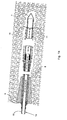
FIGURE 1a illustrates the device and the technique of the present invention, in the case of reinforcement of an upward-tilted hole; -
FIGURE 1b illustrates the device and technique of the present invention, in the case of reinforcement of a downward-tilted hole; -
FIGURE 2a shows a detail ofFig. 1a ; -
FIGURE 2b shows a detail ofFig. 1b ; -
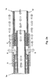
FIGURE 3 is a cross section view (section A-A ofFig. 4b ) of the device of the present invention; -
FIGURE 4a is an exploded and longitudinal section view (section B-B,Fig. 4b ) of the central part of the device of the present invention, shown in assembled state inFigs. 2a and2b ; -
FIGURE 4b is an exploded side view of the central part of the device of the present invention, entirely analogous to the view ofFig. 4a . - The present invention will now be described by examining its particular characteristics, which would allow a man skilled in the art of the field to actuate it. Other details, which are known and considered to be obvious for a man skilled in the art, will be omitted from the description.
- In the following part of the description, the term "fiberglass-reinforced plastic" will be frequently used. Nevertheless, since the invention could be applied by using another equally stable and non-polluting material, with mechanical/physical properties similar to those of fiberglass-reinforced plastic, below (except in the claims) the term fiberglass-reinforced plastic signifies a stable, non-polluting chemical material which could be employed, due to its mechanical qualities similar to fiberglass-reinforced plastic (lightness, strength etc.), in place of actual fiberglass-reinforced plastic.
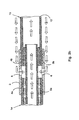
- In its preferred, non-limiting or non-binding embodiment shown in the figures, the device comprises:
- a tubular fiberglass-reinforced plastic element, constituted by a first tubular section made of fiberglass-reinforced
plastic 1a and by a second tubular section made of fiberglass-reinforcedplastic 1b, constituting separate pieces but connected together via coupling or interference by means of acollar 2, preferably made of fiberglass-reinforced plastic.
The pressure-insertion of thecollar 2 between the twotubular sections sections same collar 2; - an external sleeve 3 (
Figs. 2a and2b ), preferably metal, having twofemale threads male threads tubular sections sleeve 3 has, for example, fourtransverse holes 6 for the passage of the grout or the like situated at angular distances of 90° around the circumference of thesleeve 3; - a (seal) closure element, or cap 7 (see
Figs. 1a ,1b ) which covers the "distal" part (i.e.hole 8 bottom side) of the device of the invention when inserted in thereinforcement hole 8, or better yet which closes the second tubular fiberglass-reinforcedplastic section 1b; thiscap 7 could be made of metal and among other things serves to prevent the accidental entrance of soil or the like into thetubular element 1a+1b, especially into the second tubular fiberglass-reinforcedplastic section 1b. - It is observed that the
component 9 constitutes the already-knownhole 8 mouth caulking made with quick-setting mortars or possibly constituted by a cap made of expanded molded PE. Thecomponent 9 ensures the watertight seal with the wall of the mouth of the hole 8 (as in the prior art) and with the cylindrical external wall of the end (hole mouth side) of the first tubular fiberglass-reinforcedplastic section 1a. Thecomponent 9 can therefore be considered as not making up part of the tubular device of the present invention. - In addition, it is observed that the volume occupied by the
components - The specific structure (in this preferred embodiment of the invention) will now be described of the two
tubular sections - Of course, the first tubular fiberglass-reinforced
plastic section 1a extends from the screwing zone in themetal sleeve 3 up to (and beyond) the mouth of thehole 8, while the second tubular fiberglass-reinforcedplastic section 1b extends from its screwing zone in the other side of thesleeve 3 up to thecap 7. - The first tubular fiberglass-reinforced
plastic section 1a is actually formed by two coaxial fiberglass-reinforcedplastic tubes 10, 10' (see cross section ofFig. 3 ), connected with each other so as to form a single piece, as indicated. Theinternal tube 10 extends a certain distance beyond the edge (distal end) of the external tube 10' whose end (as said) is threaded. On the other hand, theinternal tube 10 is smooth. From the production standpoint of the firsttubular section 1a, this could obtained by means of molding of a whole fiberglass-reinforced plastic tube having the structure indicated inFig. 3 , and by means of turning one end of the same until the internal projectingtube 10 appears completely smooth. - The second tubular fiberglass-reinforced
plastic section 1b is instead constituted by asimple tube 12 made of fiberglass-reinforced plastic, i.e. without internal tube, but with one end provided with the aforesaidmale thread 5b. - It will now be described how the device of the present invention can be used in the reinforcement of the excavation face of a tunnel.
- The grout or the like, whose reinforcement will be constituted at the conclusion of the work by the tubular device of the invention, is pressure-inserted into the
related hole 8 made in the face of the tunnel through the so-called "jacket" of the tubular device, i.e. between the twotubes 10, 10'. Once it has exited from the external tube 10' and reached thesleeve 3, itstransverse holes 6 and theseal collar 2, the grout inevitably diverges and exits from thetransverse holes 6. Then, as indicated by the arrows (which show the path of the grout in a very simplified but effective manner), the same begins to rise until it reaches the zone of the hole bottom. Since the pressure of the (grout) fluid between the wall of thehole 8 and the external wall of the tubular device continues to grow, this fluid is obliged to re-enter the device through the transverse holes 11 (indicated inFig. 1a ) entirely analogous to theholes 6, which are made on the wall of the second tubular fiberglass-reinforcedplastic section 1b, near the bottom of thehole 8. As indicated inFigs. 1a ,2a , the fluid, returning into thetube 12 constituting the second tubular fiberglass-reinforcedplastic section 1b, once again descends towards the mouth of thehole 8 by passing through theinternal tube 10 of the firsttubular section 1a. Once the fluid has exited (at the point indicated by thearrow 13 inFig. 1a ), one will be certain that thereinforcement hole 8 has been completely filled with grout or the like and the tubular device of the invention will remain inside as its reinforcement. - Thus, the device of the present invention will simultaneously act as a means for carrying out the injection of the grout or the like in the
hole 8, as a means for verifying the complete filling of thehole 8 with the grout and as a means of fiberglass-reinforced plastic reinforcement (such material being stable and ecologically acceptable). - These three functions, integrated in one single object, constitute the true strength of the invention. The spoil deriving from the excavation following the reinforcement can therefore be reused for other construction works and in any case will not have to be deposited in a suitable dump for polluting materials.
- In this case, the grout is injected directly into the internal tube 10 (rather than between the
tubes 10, 10'), before exiting from thetransverse holes 11 of the second tubular section. The grout descends by gravity towards the bottom of thehole 8 but then, once this bottom is filled, it rises towards the mouth of thehole 8 according to the path indicated by the arrows. It then enters into the "jacket" of the tubular device of the invention, i.e. into the air space between the twotubes 10, 10' of the firsttubular section 1a, after having entered into thesleeve 3 through its transverse holes 6 (seeFig. 2b in particular). Indeed, since - once the grout has exited from the holes 11 - the pressure of the grout situated between the wall of thehole 8 and the external wall of the tubular device would continue to increase, the grout is obliged to re-enter the device (as in the preceding case a), this time through the holes 6 (rather than 11). It is observed that each of the two injection methods (case a and case b) are specific for a particular tilt of thehole 8. The method of case a) is also applicable when thehole 8 is horizontal or substantially so. - In other words, the method of case a would not be applicable if the
hole 8 is tilted downward, and the technique described in case b could not be employed if the hole is tilted upward. Indeed, employing the method b) for ahole 8 directed upward, one would probably not be able to fill the entire bottom of the hole 8 (hole bottom side, or distal side) with grout. Likewise, employing the method a) for a hole tilted downward, it would probably not be possible to fill the entire side of the hole next to the component 9 (hole mouth side, or proximal side) with grout. - In summary, in case a) there is a hole mouth side injection (the fluid material exits from the device at the
sleeve 3 situated in proximal position) and a hole bottom side vent (the fluid material re-enters the device through thetransverse holes 11 closest to the bottom of the hole 8). In case b), there is a hole bottom side injection (the fluid material exits from the device at the distal transverse holes 11) and a hole mouth side vent (the fluid material re-enters the device through the proximal transverse holes 6). It must be noted that the use of reinforcements made of composite material commonly indicated as fiberglass-reinforced plastic, intended for underground use, can be deemed consolidated practice. - In particular, in the making of tunnels, intensive applications of bars, tubes or integrated systems of various complexity (reinforcements coupled with injection vehicles or perforation and injection systems), they are used in techniques for improving the characteristics of the mass at the excavation core and at the borders of the cavity (ADECO-RS Method) or for radial riveting ahead of the face or from the pilot tunnel.
- Nevertheless, the originality and specificity of the present invention lies in the fact that the "double-tube" reinforcement - as represented in the section of
Fig. 3 - does not comprise thermoplastic materials, and in addition to acting as reinforcement it also allows verifying, due to the double passage, the completed filling of thehole 8 with the hardenable fluid filling material (grout or the like). - In general, the present invention is not limited to a round external section of the tubular device. The latter could have a square or generally polygonal shape, even if the round section is preferable.
- In addition, in general additional vents (or injection holes) could be present, closer together in longitudinal direction (i.e. not only distributed on a plane transverse to the tubular device as in the preceding detailed description), hole bottom side and/or hole mouth side, respectively.
- The present invention is therefore not limited to the exact configuration of the tubular device shown in the drawings and corresponding to the preferred embodiment of the invention. Indeed, it is extended to all those configurations which can be deemed easily inferable from the present concrete embodiment for an average man skilled in the art.
Specifically, the relative operating modes are the following:
Claims (10)
- A tubular device to be used in the reinforcement techniques of the excavation face in a tunnel, characterized in that it is substantially entirely made of stable, non-polluting material, preferably fiberglass-reinforced plastic, and having a lateral wall, a first proximal end, or hole mouth side end, from which a hardening fluid material is injected, and a second distal end, or hole bottom side end; the device also being characterized in that it has:- at least one first internal longitudinal channel, which extends inside the tubular device, between one or more first openings situated at the proximal end, up to one or more proximal holes (6) which cross through the lateral wall of the tubular device in a zone that is far from the distal end,- at least one second internal longitudinal channel, not intercommunicating with said first internal longitudinal channel, and which extends inside the tubular device from one or more second openings situated at the proximal end of the tubular device, up to one or more distal holes (11) which cross through the lateral wall of the tubular device in a zone that is close to its distal end, situated between the latter and the zone of said proximal holes (6);wherein,
said first internal longitudinal channel communicates with the tubular device exterior only through said first openings and said one or more proximal holes (6), and
said second internal longitudinal channel communicates with the tubular device exterior only through said second openings and said one or more distal holes (11). - A tubular device according to claim 1, characterized in that it comprises a liquid seal closure cap (7) arranged at its distal end.
- A tubular device according to claim 1 or 2, characterized in that it has a substantially round section.
- A tubular device according to claim 1 or 2, characterized in that it has a substantially polygonal section.
- A tubular device according to any one of the preceding claims, characterized in that it has a first tubular section (1a) and a second tubular section (1b), wherein the second tubular section (1b) consists of a simple tube (12) with free inner passage constituting a first part of said second internal longitudinal channel, while the first tubular section (1a) has a double-tube structure, since it is composed of an internal
tube (10) and an external tube (10') coaxial thereto, wherein, in addition, said first internal longitudinal channel extends between the internal tube (10) and the external tube (10'), while the remaining part of the second internal longitudinal channel extends through the internal tube (10). - A tubular device according to claim 5, characterized in that said first tubular section (1a) has a distal end as well as a proximal end corresponding with said proximal end of the tubular device, and said second tubular section (1b) has a proximal end as well as a distal end corresponding with said distal end of the tubular device, the proximal end of the second tubular section (1b) being connected, e.g. through screwing (4a, 4b, 5a, 5b), by means of a sleeve (3), to the distal end of the first tubular section (1a); wherein said sleeve (3) has said proximal holes (6) and said second tubular section (1b) has said distal holes (11).
- A tubular device according to claim 6, characterized in that:- the outer diameter of the first tubular section (1a) is equal to the outer diameter of the second tubular section (1b), while the outer diameter of said internal tube (10) is less than the inner diameter of the second tubular section (1b) constituting the simple tube (12);- the internal tube (10) projects beyond the external tube (10'), in the direction of the distal end of the tubular device, and is inserted for a determinate section within the second tubular section (1b); and- between the outer wall of the internal tube (10) and the inner wall of the simple tube (12), a collar (2) is inserted via interference which ensures a liquid seal closure.
- A tubular device according to claim 7, characterized in that said collar (2) is made of fiberglass-reinforced plastic.
- A tubular device according to claim 6 or 7, characterized in that said sleeve (3) is a metal sleeve.
- A process for reinforcing the excavation face of a tunnel, comprising the following steps:- after having made a perforation for obtaining a relative hole (8) on the wall of the excavation face, a tubular device in accordance with claim 1 is inserted into the hole (8), possibly with the aid of centering means;- the hole mouth caulking (9) is carried out, for example by means of quick-setting cement mixtures or by means of the insertion of a cap (9) made of expanded spongy material;- depending on the tilt of the hole (8), one proceeds in the following manner:a) if the hole (8) is horizontal or has a tilt directed upward starting from the mouth of the hole itself, then a hardening fluid material (e.g. a cement mixture) is injected through said first internal longitudinal channel, from the first proximal opening(s), until said hardening fluid, passing through said proximal holes (6), exits from the tubular device before returning, once the entire hole (8) is filled, into the same tubular device through its distal holes (11), passing through the second internal longitudinal channel and finally exiting from the device through said one or more second openings situated at the proximal end;b) if the hole (8) has a tilt directed downward starting from the mouth of the hole itself, then a hardening fluid material (e.g. a cement mixture) is injected through said second internal longitudinal channel, from the second proximal opening(s), until said hardening fluid, passing through said distal holes (11), exits from the tubular device before returning, once the entire hole (8) is filled, into the same tubular device through its proximal holes (6), then passing through the first internal longitudinal channel and finally exiting from the device through said one or more first openings situated at the proximal end.
Applications Claiming Priority (1)
| Application Number | Priority Date | Filing Date | Title |
|---|---|---|---|
| ITRM2008A000682A IT1392355B1 (en) | 2008-12-19 | 2008-12-19 | TUBULAR DEVICE IN NON-POLLUTING STABLE MATERIAL, PREFERABLY VETRORESINE, TO BE USED IN THE EXCAVATION FRONT CONSOLIDATION TECHNIQUES IN THE GALLERY. |
Publications (1)
| Publication Number | Publication Date |
|---|---|
| EP2199542A1 true EP2199542A1 (en) | 2010-06-23 |
Family
ID=41128206
Family Applications (1)
| Application Number | Title | Priority Date | Filing Date |
|---|---|---|---|
| EP09425508A Withdrawn EP2199542A1 (en) | 2008-12-19 | 2009-12-14 | Tunnel reinforcement tubular device of non-polluting material |
Country Status (2)
| Country | Link |
|---|---|
| EP (1) | EP2199542A1 (en) |
| IT (1) | IT1392355B1 (en) |
Citations (4)
| Publication number | Priority date | Publication date | Assignee | Title |
|---|---|---|---|---|
| DE29900432U1 (en) * | 1999-01-13 | 1999-04-22 | Schran Bergbau Baumaschinen Bo | Mountain anchor system |
| US20020034424A1 (en) * | 2000-04-10 | 2002-03-21 | Wolfgang Ludwig | Tubular anchor |
| EP1939394A2 (en) * | 2006-12-19 | 2008-07-02 | Minova International Limited | Anchor with grout jacket |
| EP2065559A2 (en) * | 2007-11-30 | 2009-06-03 | HILTI Aktiengesellschaft | Self-boring compound anchoring element |
-
2008
- 2008-12-19 IT ITRM2008A000682A patent/IT1392355B1/en active
-
2009
- 2009-12-14 EP EP09425508A patent/EP2199542A1/en not_active Withdrawn
Patent Citations (4)
| Publication number | Priority date | Publication date | Assignee | Title |
|---|---|---|---|---|
| DE29900432U1 (en) * | 1999-01-13 | 1999-04-22 | Schran Bergbau Baumaschinen Bo | Mountain anchor system |
| US20020034424A1 (en) * | 2000-04-10 | 2002-03-21 | Wolfgang Ludwig | Tubular anchor |
| EP1939394A2 (en) * | 2006-12-19 | 2008-07-02 | Minova International Limited | Anchor with grout jacket |
| EP2065559A2 (en) * | 2007-11-30 | 2009-06-03 | HILTI Aktiengesellschaft | Self-boring compound anchoring element |
Also Published As
| Publication number | Publication date |
|---|---|
| ITRM20080682A1 (en) | 2010-06-20 |
| IT1392355B1 (en) | 2012-02-28 |
Similar Documents
| Publication | Publication Date | Title |
|---|---|---|
| KR101070072B1 (en) | A multistaged equipment of pipe grouting by double packer system and its construction | |
| EP2414634B1 (en) | A grout delivery system for a rock bolt | |
| CN110300826B (en) | Duct piece, duct piece assembly and grouting device | |
| KR101045727B1 (en) | A multistaged equipment of pipe grouting by double packer system and its constructing method | |
| KR101580961B1 (en) | Reinforced direct boring attached imbedded bit at head steelpipe and one shot grouting in tunneling method | |
| KR101115783B1 (en) | Method for direct boring and grouting using duplicate pipe | |
| KR100777966B1 (en) | Innovation one shot grouting prefabricated steel pipe installation and using reinforcing tunnelling method | |
| KR100933230B1 (en) | Reinforcing grouting device | |
| KR101871238B1 (en) | Method for tunnel construction using grouting technology | |
| EP2199542A1 (en) | Tunnel reinforcement tubular device of non-polluting material | |
| KR102162788B1 (en) | Empty space filing structure and grouting method using thereof | |
| KR101898338B1 (en) | Anker assembly for anchoring weak foundation | |
| KR101644098B1 (en) | Bulbed cable bolt | |
| JP2008081990A (en) | Shield tunnel construction method | |
| KR100475416B1 (en) | Micro silica grouting method reinforced with a steel pipe | |
| KR101309145B1 (en) | Nailing apparatus of pressing type and, reinforcement methods for ground using the same | |
| KR20200099358A (en) | Method of grouting with steel pipe for reinforcemnet of tunnel section and structure by the same in constructing tunnel | |
| KR101219802B1 (en) | Grout same time injection method for steel pipe reinforcement | |
| KR20190136221A (en) | Grouting apparatus the grouting method thereof | |
| KR102167050B1 (en) | A GROUNTING METHOD FOR REINFORCING CIP(Cast-In place Pile) WALL | |
| KR20190091741A (en) | Grouting apparatus for reinforcing tunnel and the manufacture method thereof | |
| KR102260944B1 (en) | Reinforced steel pipe one shot grouting and constructing method thereof | |
| KR20040101102A (en) | Grouting apparatus having a adapting type packer | |
| JP7399415B2 (en) | Stopper for concrete parts | |
| KR200422928Y1 (en) | Innovation one shot grouting prefabricated steel pipe installation |
Legal Events
| Date | Code | Title | Description |
|---|---|---|---|
| PUAI | Public reference made under article 153(3) epc to a published international application that has entered the european phase |
Free format text: ORIGINAL CODE: 0009012 |
|
| AK | Designated contracting states |
Kind code of ref document: A1 Designated state(s): AT BE BG CH CY CZ DE DK EE ES FI FR GB GR HR HU IE IS IT LI LT LU LV MC MK MT NL NO PL PT RO SE SI SK SM TR |
|
| AX | Request for extension of the european patent |
Extension state: AL BA RS |
|
| 17P | Request for examination filed |
Effective date: 20101202 |
|
| 17Q | First examination report despatched |
Effective date: 20110329 |
|
| STAA | Information on the status of an ep patent application or granted ep patent |
Free format text: STATUS: THE APPLICATION IS DEEMED TO BE WITHDRAWN |
|
| 18D | Application deemed to be withdrawn |
Effective date: 20110818 |