EP2199504B1 - Mécanisme de fermeture de porte et enveloppe pour appareils électriques comportant un tel mécanisme - Google Patents
Mécanisme de fermeture de porte et enveloppe pour appareils électriques comportant un tel mécanisme Download PDFInfo
- Publication number
- EP2199504B1 EP2199504B1 EP09179927A EP09179927A EP2199504B1 EP 2199504 B1 EP2199504 B1 EP 2199504B1 EP 09179927 A EP09179927 A EP 09179927A EP 09179927 A EP09179927 A EP 09179927A EP 2199504 B1 EP2199504 B1 EP 2199504B1
- Authority
- EP
- European Patent Office
- Prior art keywords
- handle
- bolt
- door
- plate
- mechanism according
- Prior art date
- Legal status (The legal status is an assumption and is not a legal conclusion. Google has not performed a legal analysis and makes no representation as to the accuracy of the status listed.)
- Active
Links
Images



Classifications
-
- E—FIXED CONSTRUCTIONS
- E05—LOCKS; KEYS; WINDOW OR DOOR FITTINGS; SAFES
- E05B—LOCKS; ACCESSORIES THEREFOR; HANDCUFFS
- E05B7/00—Handles pivoted about an axis parallel to the wing
-
- E—FIXED CONSTRUCTIONS
- E05—LOCKS; KEYS; WINDOW OR DOOR FITTINGS; SAFES
- E05C—BOLTS OR FASTENING DEVICES FOR WINGS, SPECIALLY FOR DOORS OR WINDOWS
- E05C3/00—Fastening devices with bolts moving pivotally or rotatively
- E05C3/12—Fastening devices with bolts moving pivotally or rotatively with latching action
- E05C3/16—Fastening devices with bolts moving pivotally or rotatively with latching action with operating handle or equivalent member moving otherwise than rigidly with the latch
- E05C3/162—Fastening devices with bolts moving pivotally or rotatively with latching action with operating handle or equivalent member moving otherwise than rigidly with the latch the handle or member moving essentially towards or away of the plane of the wing or frame
-
- E—FIXED CONSTRUCTIONS
- E05—LOCKS; KEYS; WINDOW OR DOOR FITTINGS; SAFES
- E05C—BOLTS OR FASTENING DEVICES FOR WINGS, SPECIALLY FOR DOORS OR WINDOWS
- E05C3/00—Fastening devices with bolts moving pivotally or rotatively
- E05C3/12—Fastening devices with bolts moving pivotally or rotatively with latching action
- E05C3/16—Fastening devices with bolts moving pivotally or rotatively with latching action with operating handle or equivalent member moving otherwise than rigidly with the latch
- E05C3/22—Fastening devices with bolts moving pivotally or rotatively with latching action with operating handle or equivalent member moving otherwise than rigidly with the latch the bolt being spring controlled
- E05C3/30—Fastening devices with bolts moving pivotally or rotatively with latching action with operating handle or equivalent member moving otherwise than rigidly with the latch the bolt being spring controlled in the form of a hook
-
- E—FIXED CONSTRUCTIONS
- E05—LOCKS; KEYS; WINDOW OR DOOR FITTINGS; SAFES
- E05B—LOCKS; ACCESSORIES THEREFOR; HANDCUFFS
- E05B13/00—Devices preventing the key or the handle or both from being used
- E05B13/10—Devices preventing the key or the handle or both from being used formed by a lock arranged in the handle
-
- E—FIXED CONSTRUCTIONS
- E05—LOCKS; KEYS; WINDOW OR DOOR FITTINGS; SAFES
- E05B—LOCKS; ACCESSORIES THEREFOR; HANDCUFFS
- E05B5/00—Handles completely let into the surface of the wing
Definitions
- the invention relates to door closing mechanisms, in particular, but not exclusively, in enclosures for electrical appliances.
- the invention aims to provide such a closure mechanism, which is particularly simple, convenient and economical.
- the bolt and the handle are each provided with its own elastic return means and its own limit stop and the manner in which the handle and the bolt are movable during configuration changes makes it possible to implement the door closing mechanism with a particularly small number of components.
- the mechanism according to the invention can be implemented with only the handle, the bolt and the elastic return means.
- the mechanism comprises on said door a mounting cradle comprising a plate.
- Such a cradle makes it possible to implement the door closing mechanism in a particularly efficient manner, both in manufacture and use.
- the invention also aims, in a second aspect, an envelope for electrical devices comprising a mechanism as explained above.
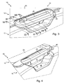
- the cabinet cover 10 illustrated in the drawings comprises a dormant portion 11 intended to be rigidly attached to a cabinet body (not shown), a door 12 articulated on the dormant portion along its side opposite to that visible on the figures 1 , 3 and 4 ; and a mechanism 13 for closing the door 12.
- the cover 10 is designed to close a box body provided with two fixing rails for modular electrical devices, such as differential switches and circuit breakers, so that two rows each formed by a box can be installed in this body. set of modular electrical appliances arranged side by side on one of the rails.
- the dormant portion 11 of the cover 10 has a central panel 14 in which are formed two elongated windows 15 each closed by a cover 16.
- Each window 15 is provided to allow the passage of the nose of electrical appliances arranged in a row on one of the rails.
- the covers 16 are removed in whole or in part.
- Central panel 14 is skirted over its entire periphery, which here is generally rectangular with rounded corners, by a protruding flange 17.
- the flange 17 is surrounded by a peripheral flange 18, which delimits the periphery of the dormant portion 11, which periphery, like the periphery of the panel 14, is generally rectangular with rounded corners.
- the space between the inner rim 17 and the peripheral rim 18 forms a gutter 19.
- the slope of the trough 19 formed by the internal rim 17 is less than the slope formed by the peripheral rim 18, the edge 20 of the inner rim 17 being recessed with respect to the edge 21 of the peripheral rim 18.
- the wafer 20 is formed by a bead of a seal 22 that includes the internal rim 17.
- the cover 10 is provided to bear on the casing body (not shown) by its edge 23 located at the end of a side wall located at the right of the outer wall of the peripheral flange 18.
- each chimney 24 is aligned with a chimney of the body, so that, for each pair of chimneys, the rod of a locking screw can pass from the bore of the chimney 24 to that of the chimney of the body to engage with it.
- the door 12 comprises a central panel 25 around the edge of which is a flange 26 having generally the same contour as the inner flange 17.
- the edge 27 of the flange 26 is relatively narrow and bears, when the door 12 is closed, on the seal 22 forming the wafer 20 (see more particularly the figure 5 ).
- the door 12 has a cradle 30 for mounting the closure mechanism 13.
- the cradle 30 comprises a plate 31, a counterplate 32, two cheeks 33, a frontage 34 and a projection 35.
- the plate 31 is oriented parallel to the general orientation plane of the door 12.
- Counterplate 32 and cheeks 33 protrude transversely from plate 31 towards the opposite of dormant portion 11.
- the plate 31 has a contour generally isosceles trapezium whose opposite non-parallel sides are rounded.
- the larger of the two parallel sides belongs to the periphery of the door 12.
- Backplate 32 extends along the smaller of the parallel sides and each flange 33 extends along a respective non-parallel side.
- the counterplate 32 and the flanges 33 form a continuous wall which borders the plate 31 along its recessed sides with respect to the periphery of the door 12.
- the facade 34 protrudes transversely from the plate 31 along its side belonging to the periphery of the door 12 (larger of the two parallel sides), towards the dormant portion 11, that is to say that the facade 34 protrudes from the platinum 31 of its opposite face to that which counter platinum 32 and the cheeks 33.
- the facade 34 is extended by a wall located at the same level as the corresponding cheek 33, to which it is connected.
- the projection 35 has a portion opposite the plate 31. This portion projects transversely towards the side of the backplate 32 and the cheeks 33 opposite to that by which the backplate 32 and the cheeks 33 are connected to the plate 31.
- the projection 35 further comprises, on either side of the plate 31, a portion extending beyond the corresponding cheek 33 and connecting to the front 34 (see more particularly the figure 7 ).
- the portion of the projection 35 opposite the plate 31 is set back with respect to the facade 34 with generally the shape of a narrow band along the backplate 32.
- this narrow band is inclined towards the opposite of the plate 31.
- the cradle 30 forms, on the one hand, a central recess 36 delimited by the plate 31, the counterplate 32, the cheeks 33 and the projection 35; and, on the other hand, two lateral recesses 37 each delimited by the facade 34 and the projection 35.
- the central recess 36 is open towards the opposite of the dormant portion 11 and the lateral recesses 37 are open towards the dormant portion 11.
- the mechanism 13 comprises a control handle 40, a bolt 41, a spring 42 for returning the handle 40 and two springs 43 for returning the bolt 41.
- the handle 40 comprises a plate 45 and two legs 46, each located at a respective end of the plate 45.
- the plate 45 is elongate with its opposite narrow ends which are rounded.
- the plate 45 On the side that we see on the left on figures 1 , 3 and 4 the plate 45 has a knockout seal 47, here circular contour. Between the seal 47 and the opposite end, the plate 45 has an elongated opening 48.
- the jamb 46 that is seen to the left of the handle 40 on the figure 1 it moves from the plate 45 to the dormant portion 11. It is provided with a hinge pin 49 oriented parallel to the general direction of elongation of the plate 45. In the pin 49 is formed a coaxial bore 50.
- the other leg 46 that includes the handle 40 at the end that is seen to the right on the figure 1 is identical, except that it is the mirror image.
- the two pins 49 are aligned parallel to the general direction along which the plate 45 extends, eccentrically; and that the trunnion 49 of each of the two legs 46 protrudes towards the outside of the handle 40.
- the legs 46 are slightly elastically flexible in order to be closer to one another
- Each opening 51 is formed in a respective cheeks 33, from the plate 31 and from the front 34.
- the opening 51 also has a slight notch in the facade 34.
- the plate 45 of the handle 40 is oriented parallel to the plate 31 of the cradle 30, and therefore parallel to the general orientation plane of the door 12.
- the outer surface of the plate 45 is then substantially flush with the edge of the projection 35 while about half of the plate 45, located beyond the legs 46, is in excess of the outer surface of the facade 34.
- the plate 45 is inclined towards the plate 31 and towards the backplate 32.
- the rim 18 of the dormant portion 11 has a recess 55 in correspondence with the recess 36 of the cradle 30, when the door 12 is closed (see more particularly the figure 4 ).
- the handle 40 can pivot only between the folded position and the raised position, it is provided, here at the center of the side wall of the plate 45 opposite the counter plate 32, a lug 56 having a right face 57 turned towards the projection 35 and an inclined face 58 facing the plate 31.
- the faces 57 and 58 form end stops respectively fixing the folded position and the raised position (see more particularly the figure 2 ).
- the face 57 is in abutment against a recess 59 protruding from the backplate 32 and the projection 35.
- the spring 42 is made of spring wire with a helical central portion 60, one end of which connects to a tab 61 and the other end to a tab 62, the tabs 61 and 62 being arranged transversely relative to one another. other when the spring 42 is at rest ( figure 1 ).
- the plate 45 has a housing 63 for the central portion 60 and a notch 64 for the tab 62 while the plate 31 is provided with two ribs 66 between which is engaged the tab 61.
- the central portion 60 and the lug 62 are respectively engaged in the housing 63 and in the notch 64.
- the lug 61 is placed between the ribs 66 at the same time as the handle 40 is snapped into the cradle 30.
- the spring 42 urges the handle 40 towards the folded position where the face 57 of the lug 56 bears against the step 59.
- the bolt 41 comprises a plate 70, two legs 71 each located at a respective end of the plate 70, and two tabs 72 of support with the handle 40, located at a distance from one another between the legs 71.
- the bolt 41 has a length similar to that of the handle 40 and the plate 31.
- the plate 70 is generally rectangular.
- the legs 71 project from the long side of the plate 70 opposite that forming one end of the notch 75.
- Each leg 71 is provided with a hinge pin 77 oriented parallel to the general direction along which the plate 70 extends.
- the pins 77 are aligned. They project each towards the end of the bolt 41 that is seen to the right on the figure 1 .
- Each pin 77 has a diameter corresponding to that of the bore 50 of the journals 49.
- each pin 77 is engaged in the bore 50 of one of the journals 49, the bolt 41 being thus pivotally movable coaxially with the handle 40.
- the bearing lugs 72 project from the plate 70 from the long side opposite that forming one end of the notch 75.
- Each tab 72 has the shape of a bracket whose distal branch is oriented transversely to the plate 70.
- the distal end surface 78 of each tab 72 forms a bearing surface for the handle 40, here intended to come into contact with the slice 79 of the side wall of the plate 45 ( figure 9 ).
- the plate 31 For the passage of the support legs 72, the plate 31 has two openings 80.
- the plate 31 For the passage of the jamb 71 that we see on the right on the figure 1 the plate 31 has an opening 81 near the corresponding opening 51.
- the bolt 41 is put in place after the handle 40, as explained below.
- the bolt 70 is first placed in a position where the jamb 71 that is seen to the right on the figure 1 is opposite the opening 81, each of the support lugs 72 is opposite one of the openings 80 and the jamb 71 that is seen to the left on the figure 1 is next to the lateral recess 37 that we see on the left.
- the bolt 41 is then brought closer to the plate 31, until the trunnions 77 of the legs 71 are aligned with the trunnions 49 of the handle 40 and the bolt 41 is moved in the alignment direction to engage the trunnions 77 in the bores 50.
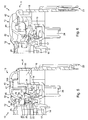
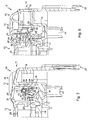
- the bolt 41 is pivotally movable, coaxially with the handle 40, between the rest position illustrated on the figure 2 (mechanism 13 in the open door configuration) and the unlocking position illustrated on the Figures 9 and 10 (door release configuration).
- the plate 70 of the bolt 41 is oriented transversely to the plate 31 of the cradle 30 and therefore transversely to the general orientation plane of the door 12.
- the springs 43 urge the bolt 41 towards the rest position ( figure 2 ).
- Each spring 43 is made of spring wire with a helical central portion 90, one end of which connects to a tab 91 and the other end to a tab 92.
- the end of the tab 91 opposite the central portion 90 is connected to the tail 85.
- the tabs 91 and 92 are parallel to each other when the spring 43 is at rest ( figure 1 ).
- each leg 71 has a groove 93 for the lug 92 and, opposite the trunnion 77, a finger 94 on which is threaded the central portion 90.
- the bolt 41 can not pivot beyond the rest position, it is provided, here in the center of the plate 70 near its end opposite the notch 75, a lug 95 whose coming abutting on the platinum 31 sets the rest position (see more particularly the figure 2 ).
- the plate 31 acts as a limit stop against which is applied the bolt 41 in the absence of external stress (rest position).
- the redan 59 plays the role of an end stop against which is applied the handle 40 in the absence of external stress (rest position corresponding to the folded position).
- the handle 40 When the door 12 is closed (configuration illustrated on the figures 3 and 5 to 8 ), the handle 40 is, as when the door is open, in the rest position or folded while the bolt 41 is in a locking position where it is engaged to hook with the teeth 76 which is provided with the dormant portion 11.
- Each tooth 76 protrudes from the wall of the inner rim 17 forming one of the slopes of the channel 19, which receives the plate 70 when the door 12 is closed.
- each tooth 76 has a ramp 96 and a retaining face 97 set back from the ramp 96.
- the notch 75 of the bolt 41 has a ramp 98 and a retaining face 99 set back from the ramp 98.
- the ramp 98 has an inclined portion and a straight portion.
- the inclined portion extends from the end which is seen below in the drawings (distal end of the bolt 41) to the right portion.
- the straight portion extends from the inclined portion to the retaining face 99.
- the ramp 98 comes into contact with the ramp 96, which has the effect of driving the bolt 41 against the springs 43 (direction of rotation where the lug 95 away from the plate 31), to a crossing position of the teeth 76, where the edge between the ramp 98 and the retaining face 99 (notch 75) is at the edge between the ramp 96 and the retaining face 97 (teeth 76).
- the user moves the handle 40 from the folded position (rest position) to the raised position illustrated on the figures 4 , 9 and 10 (unlock position).
- the bolt 41 When the handle 40 moves from its rest position to its unlocked position, the bolt 41 remains in the locking position as long as the bearing surface 79 of the handle 40 has not come into contact with the bearing surface 78 of the bolt 41. When the contact is established, the bolt 41 is driven by the handle 40 against the springs 43.
- the bolt 41 When the handle 40 is in the unlocked position (raised position, fixed by the application of the lug 56 against the plate 31), the bolt 41 is also in an unlocked position, where it is cleared teeth 76, so that the door 12 can be opened.
- the mechanism 13 is thus brought automatically back into the open door configuration ( figure 2 ).
- the cover 47 of the handle 40 closes a housing 100 ( figure 5 ) designed to receive the barrel of a lock (not shown) for locking the handle 40 in the rest position.
- the handle 40 can not leave the rest position, it can not act on the bolt 41, so that in the closed door configuration, the bolt 41 can be driven by the handle 40 to the unlocked position.
- a single tooth such as 76 or more than two teeth such as 76; there is provided a single spring such as 43 or more than two springs such as 43; and / or there are provided several springs such as 42.
- it implements one or more different retaining members of the teeth 76 and / or elastic return means different from the springs 42 and 43.
- the handle such as 40 is mounted differently, for example by being movable in translation rather than pivoting; the support legs such as 72 are provided on the handle such as 40 rather than the bolt such as 41 or both on the handle and the bolt; he there is only one support leg or more than two; and / or the bolt is shaped differently, being for example shorter than the handle 40 or the plate 31.
- the device to which belongs the door 12 is of a different type, for example a box provided for a single row of modular electrical appliances or for more than two rows, is of another type electric enclosure that a cabinet, for example a cabinet, or is a device different from an electrical envelope, for example a medicine cabinet.
Landscapes
- Engineering & Computer Science (AREA)
- Mechanical Engineering (AREA)
- Casings For Electric Apparatus (AREA)
- Patch Boards (AREA)
Priority Applications (1)
| Application Number | Priority Date | Filing Date | Title |
|---|---|---|---|
| PL09179927T PL2199504T3 (pl) | 2008-12-22 | 2009-12-18 | Mechanizm zamykający drzwiczki i obudowa dla urządzeń elektrycznych zawierająca taki mechanizm |
Applications Claiming Priority (1)
| Application Number | Priority Date | Filing Date | Title |
|---|---|---|---|
| FR0858979A FR2940343A1 (fr) | 2008-12-22 | 2008-12-22 | Mecanisme de fermeture de porte et enveloppe pour appareils electriques comportant un tel mecanisme |
Publications (2)
| Publication Number | Publication Date |
|---|---|
| EP2199504A1 EP2199504A1 (fr) | 2010-06-23 |
| EP2199504B1 true EP2199504B1 (fr) | 2012-07-25 |
Family
ID=40941534
Family Applications (1)
| Application Number | Title | Priority Date | Filing Date |
|---|---|---|---|
| EP09179927A Active EP2199504B1 (fr) | 2008-12-22 | 2009-12-18 | Mécanisme de fermeture de porte et enveloppe pour appareils électriques comportant un tel mécanisme |
Country Status (3)
| Country | Link |
|---|---|
| EP (1) | EP2199504B1 (pl) |
| FR (1) | FR2940343A1 (pl) |
| PL (1) | PL2199504T3 (pl) |
Families Citing this family (1)
| Publication number | Priority date | Publication date | Assignee | Title |
|---|---|---|---|---|
| DE102017006435A1 (de) * | 2017-07-07 | 2019-01-10 | Otto Ganter Gmbh & Co. Kg Normteilefabrik | Fallenverschluss mit betriebssicherer Betätigung |
Family Cites Families (5)
| Publication number | Priority date | Publication date | Assignee | Title |
|---|---|---|---|---|
| DE630283C (de) * | 1933-06-19 | 1936-05-25 | Hugo Karre | Schranktuergriff |
| AU4654072A (en) * | 1971-09-10 | 1974-03-21 | the STANLEY WORKS PTY. LTD | Latch mechanism |
| ES2255851B1 (es) * | 2004-12-17 | 2007-03-16 | Girbau, S.A. | Dispositivo de cierre para puerta de aparato provisto de bombo giratorio, y pestillo aplicable a tal dispositivo. |
| TR200805928T1 (tr) * | 2006-03-29 | 2011-04-21 | Arçeli̇k Anoni̇m Şi̇rketi̇ | Bir ev cihazı |
| DE102006045098A1 (de) * | 2006-09-21 | 2008-04-10 | Karl Simon Gmbh & Co. Kg | Möbelbeschlag |
-
2008
- 2008-12-22 FR FR0858979A patent/FR2940343A1/fr active Pending
-
2009
- 2009-12-18 PL PL09179927T patent/PL2199504T3/pl unknown
- 2009-12-18 EP EP09179927A patent/EP2199504B1/fr active Active
Also Published As
| Publication number | Publication date |
|---|---|
| EP2199504A1 (fr) | 2010-06-23 |
| PL2199504T3 (pl) | 2012-11-30 |
| FR2940343A1 (fr) | 2010-06-25 |
Similar Documents
| Publication | Publication Date | Title |
|---|---|---|
| FR3005481A3 (fr) | Ensemble de porte | |
| EP0837526A1 (fr) | Borne de connexion automatique, et appareil électrique équipé d'une telle borne de connexion | |
| EP4060151A1 (fr) | Commande d'ouverture extérieure à palette poly-articulée | |
| FR2889227A1 (fr) | Dispositif d'ecartement provisoire a embase clipsable | |
| EP2068409A1 (fr) | Accessoire d'angle pour goulottes à volets pivotants | |
| EP2456021A1 (fr) | Prise électrique comportant des montants latéraux mobiles en translation | |
| EP0869242B1 (fr) | Ferrure de verrouillage pour ouvrant coulissant | |
| EP1400195B1 (fr) | Appareil électroménager à panneaux articulés | |
| EP2199504B1 (fr) | Mécanisme de fermeture de porte et enveloppe pour appareils électriques comportant un tel mécanisme | |
| EP2896907A1 (fr) | Bouche de ventilation pour système d'aération | |
| EP3503322A1 (fr) | Support d'appareillage électrique recevant un élément de montage | |
| EP0592311B1 (fr) | Clip de fixation amovible et pivotante à manoeuvre manuelle, et dispositif de liaison le comportant | |
| FR2652374A1 (fr) | Poignee pour portiere de vehicule a moteur. | |
| WO2021032437A1 (fr) | Dispositif de montage d'un boîtier multi-appareillage, cadre de montage comprenant un tel dispositif de montage et dispositif multi-appareillage comprenant un tel cadre de montage et un boîtier multi-appareillage | |
| WO2011077033A2 (fr) | Dispositif d'obturation et ensemble correspondant | |
| EP1948499A1 (fr) | Dispositif d'ecartement securise a l'arrachement | |
| FR2901419A1 (fr) | Bloc de jonction pour conducteur electriques | |
| FR2853771A1 (fr) | Dispositif mecanique de fermeture pour protections de connecteur electrique | |
| EP3530851B1 (fr) | Système de verrouillage pour une porte sectionnelle à déplacement latéral | |
| FR2895939A1 (fr) | Crochet de reception d'un tourillon d'articulation | |
| EP0935271B1 (fr) | Capot à volet monté pivotant, notamment pour platine de disjoncteur | |
| EP4091018A1 (fr) | Charniere en matiere plastique | |
| EP2320012B1 (fr) | Dispositif d'ouverture et de fermeture d'une porte sur un cadre | |
| EP2510158B1 (fr) | Ensemble a cadre et tampon de fermeture du cadre notamment pour regard de chaussee | |
| EP1372232A1 (fr) | Boítier électrique avec verrou articulé |
Legal Events
| Date | Code | Title | Description |
|---|---|---|---|
| PUAI | Public reference made under article 153(3) epc to a published international application that has entered the european phase |
Free format text: ORIGINAL CODE: 0009012 |
|
| AK | Designated contracting states |
Kind code of ref document: A1 Designated state(s): AT BE BG CH CY CZ DE DK EE ES FI FR GB GR HR HU IE IS IT LI LT LU LV MC MK MT NL NO PL PT RO SE SI SK SM TR |
|
| AX | Request for extension of the european patent |
Extension state: AL BA RS |
|
| 17P | Request for examination filed |
Effective date: 20101214 |
|
| 17Q | First examination report despatched |
Effective date: 20110117 |
|
| REG | Reference to a national code |
Ref country code: DE Ref legal event code: R079 Ref document number: 602009008467 Country of ref document: DE Free format text: PREVIOUS MAIN CLASS: E05C0003300000 Ipc: E05B0007000000 |
|
| GRAP | Despatch of communication of intention to grant a patent |
Free format text: ORIGINAL CODE: EPIDOSNIGR1 |
|
| RIC1 | Information provided on ipc code assigned before grant |
Ipc: E05C 3/16 20060101ALI20120110BHEP Ipc: E05C 3/30 20060101ALI20120110BHEP Ipc: E05B 7/00 20060101AFI20120110BHEP |
|
| GRAS | Grant fee paid |
Free format text: ORIGINAL CODE: EPIDOSNIGR3 |
|
| GRAA | (expected) grant |
Free format text: ORIGINAL CODE: 0009210 |
|
| AK | Designated contracting states |
Kind code of ref document: B1 Designated state(s): AT BE BG CH CY CZ DE DK EE ES FI FR GB GR HR HU IE IS IT LI LT LU LV MC MK MT NL NO PL PT RO SE SI SK SM TR |
|
| REG | Reference to a national code |
Ref country code: GB Ref legal event code: FG4D Free format text: NOT ENGLISH |
|
| REG | Reference to a national code |
Ref country code: CH Ref legal event code: EP |
|
| REG | Reference to a national code |
Ref country code: AT Ref legal event code: REF Ref document number: 567800 Country of ref document: AT Kind code of ref document: T Effective date: 20120815 Ref country code: IE Ref legal event code: FG4D Free format text: LANGUAGE OF EP DOCUMENT: FRENCH |
|
| REG | Reference to a national code |
Ref country code: DE Ref legal event code: R096 Ref document number: 602009008467 Country of ref document: DE Effective date: 20120920 |
|
| REG | Reference to a national code |
Ref country code: PL Ref legal event code: T3 |
|
| REG | Reference to a national code |
Ref country code: NL Ref legal event code: VDEP Effective date: 20120725 |
|
| REG | Reference to a national code |
Ref country code: AT Ref legal event code: MK05 Ref document number: 567800 Country of ref document: AT Kind code of ref document: T Effective date: 20120725 |
|
| REG | Reference to a national code |
Ref country code: LT Ref legal event code: MG4D Effective date: 20120725 |
|
| PG25 | Lapsed in a contracting state [announced via postgrant information from national office to epo] |
Ref country code: CY Free format text: LAPSE BECAUSE OF FAILURE TO SUBMIT A TRANSLATION OF THE DESCRIPTION OR TO PAY THE FEE WITHIN THE PRESCRIBED TIME-LIMIT Effective date: 20120725 Ref country code: LT Free format text: LAPSE BECAUSE OF FAILURE TO SUBMIT A TRANSLATION OF THE DESCRIPTION OR TO PAY THE FEE WITHIN THE PRESCRIBED TIME-LIMIT Effective date: 20120725 Ref country code: AT Free format text: LAPSE BECAUSE OF FAILURE TO SUBMIT A TRANSLATION OF THE DESCRIPTION OR TO PAY THE FEE WITHIN THE PRESCRIBED TIME-LIMIT Effective date: 20120725 Ref country code: HR Free format text: LAPSE BECAUSE OF FAILURE TO SUBMIT A TRANSLATION OF THE DESCRIPTION OR TO PAY THE FEE WITHIN THE PRESCRIBED TIME-LIMIT Effective date: 20120725 Ref country code: IS Free format text: LAPSE BECAUSE OF FAILURE TO SUBMIT A TRANSLATION OF THE DESCRIPTION OR TO PAY THE FEE WITHIN THE PRESCRIBED TIME-LIMIT Effective date: 20121125 Ref country code: NO Free format text: LAPSE BECAUSE OF FAILURE TO SUBMIT A TRANSLATION OF THE DESCRIPTION OR TO PAY THE FEE WITHIN THE PRESCRIBED TIME-LIMIT Effective date: 20121025 Ref country code: FI Free format text: LAPSE BECAUSE OF FAILURE TO SUBMIT A TRANSLATION OF THE DESCRIPTION OR TO PAY THE FEE WITHIN THE PRESCRIBED TIME-LIMIT Effective date: 20120725 |
|
| PG25 | Lapsed in a contracting state [announced via postgrant information from national office to epo] |
Ref country code: GR Free format text: LAPSE BECAUSE OF FAILURE TO SUBMIT A TRANSLATION OF THE DESCRIPTION OR TO PAY THE FEE WITHIN THE PRESCRIBED TIME-LIMIT Effective date: 20121026 Ref country code: LV Free format text: LAPSE BECAUSE OF FAILURE TO SUBMIT A TRANSLATION OF THE DESCRIPTION OR TO PAY THE FEE WITHIN THE PRESCRIBED TIME-LIMIT Effective date: 20120725 Ref country code: SI Free format text: LAPSE BECAUSE OF FAILURE TO SUBMIT A TRANSLATION OF THE DESCRIPTION OR TO PAY THE FEE WITHIN THE PRESCRIBED TIME-LIMIT Effective date: 20120725 Ref country code: PT Free format text: LAPSE BECAUSE OF FAILURE TO SUBMIT A TRANSLATION OF THE DESCRIPTION OR TO PAY THE FEE WITHIN THE PRESCRIBED TIME-LIMIT Effective date: 20121126 Ref country code: SE Free format text: LAPSE BECAUSE OF FAILURE TO SUBMIT A TRANSLATION OF THE DESCRIPTION OR TO PAY THE FEE WITHIN THE PRESCRIBED TIME-LIMIT Effective date: 20120725 |
|
| PG25 | Lapsed in a contracting state [announced via postgrant information from national office to epo] |
Ref country code: NL Free format text: LAPSE BECAUSE OF FAILURE TO SUBMIT A TRANSLATION OF THE DESCRIPTION OR TO PAY THE FEE WITHIN THE PRESCRIBED TIME-LIMIT Effective date: 20120725 |
|
| PG25 | Lapsed in a contracting state [announced via postgrant information from national office to epo] |
Ref country code: RO Free format text: LAPSE BECAUSE OF FAILURE TO SUBMIT A TRANSLATION OF THE DESCRIPTION OR TO PAY THE FEE WITHIN THE PRESCRIBED TIME-LIMIT Effective date: 20120725 Ref country code: EE Free format text: LAPSE BECAUSE OF FAILURE TO SUBMIT A TRANSLATION OF THE DESCRIPTION OR TO PAY THE FEE WITHIN THE PRESCRIBED TIME-LIMIT Effective date: 20120725 Ref country code: DK Free format text: LAPSE BECAUSE OF FAILURE TO SUBMIT A TRANSLATION OF THE DESCRIPTION OR TO PAY THE FEE WITHIN THE PRESCRIBED TIME-LIMIT Effective date: 20120725 Ref country code: CZ Free format text: LAPSE BECAUSE OF FAILURE TO SUBMIT A TRANSLATION OF THE DESCRIPTION OR TO PAY THE FEE WITHIN THE PRESCRIBED TIME-LIMIT Effective date: 20120725 Ref country code: ES Free format text: LAPSE BECAUSE OF FAILURE TO SUBMIT A TRANSLATION OF THE DESCRIPTION OR TO PAY THE FEE WITHIN THE PRESCRIBED TIME-LIMIT Effective date: 20121105 |
|
| PG25 | Lapsed in a contracting state [announced via postgrant information from national office to epo] |
Ref country code: SK Free format text: LAPSE BECAUSE OF FAILURE TO SUBMIT A TRANSLATION OF THE DESCRIPTION OR TO PAY THE FEE WITHIN THE PRESCRIBED TIME-LIMIT Effective date: 20120725 |
|
| PLBE | No opposition filed within time limit |
Free format text: ORIGINAL CODE: 0009261 |
|
| STAA | Information on the status of an ep patent application or granted ep patent |
Free format text: STATUS: NO OPPOSITION FILED WITHIN TIME LIMIT |
|
| 26N | No opposition filed |
Effective date: 20130426 |
|
| PG25 | Lapsed in a contracting state [announced via postgrant information from national office to epo] |
Ref country code: MC Free format text: LAPSE BECAUSE OF NON-PAYMENT OF DUE FEES Effective date: 20121231 Ref country code: BG Free format text: LAPSE BECAUSE OF FAILURE TO SUBMIT A TRANSLATION OF THE DESCRIPTION OR TO PAY THE FEE WITHIN THE PRESCRIBED TIME-LIMIT Effective date: 20121025 |
|
| REG | Reference to a national code |
Ref country code: DE Ref legal event code: R097 Ref document number: 602009008467 Country of ref document: DE Effective date: 20130426 |
|
| REG | Reference to a national code |
Ref country code: IE Ref legal event code: MM4A |
|
| PG25 | Lapsed in a contracting state [announced via postgrant information from national office to epo] |
Ref country code: IE Free format text: LAPSE BECAUSE OF NON-PAYMENT OF DUE FEES Effective date: 20121218 |
|
| PG25 | Lapsed in a contracting state [announced via postgrant information from national office to epo] |
Ref country code: MT Free format text: LAPSE BECAUSE OF FAILURE TO SUBMIT A TRANSLATION OF THE DESCRIPTION OR TO PAY THE FEE WITHIN THE PRESCRIBED TIME-LIMIT Effective date: 20120725 |
|
| PG25 | Lapsed in a contracting state [announced via postgrant information from national office to epo] |
Ref country code: TR Free format text: LAPSE BECAUSE OF FAILURE TO SUBMIT A TRANSLATION OF THE DESCRIPTION OR TO PAY THE FEE WITHIN THE PRESCRIBED TIME-LIMIT Effective date: 20120725 |
|
| PG25 | Lapsed in a contracting state [announced via postgrant information from national office to epo] |
Ref country code: SM Free format text: LAPSE BECAUSE OF FAILURE TO SUBMIT A TRANSLATION OF THE DESCRIPTION OR TO PAY THE FEE WITHIN THE PRESCRIBED TIME-LIMIT Effective date: 20120725 Ref country code: LU Free format text: LAPSE BECAUSE OF NON-PAYMENT OF DUE FEES Effective date: 20121218 |
|
| PG25 | Lapsed in a contracting state [announced via postgrant information from national office to epo] |
Ref country code: HU Free format text: LAPSE BECAUSE OF FAILURE TO SUBMIT A TRANSLATION OF THE DESCRIPTION OR TO PAY THE FEE WITHIN THE PRESCRIBED TIME-LIMIT Effective date: 20091218 |
|
| REG | Reference to a national code |
Ref country code: CH Ref legal event code: PL |
|
| GBPC | Gb: european patent ceased through non-payment of renewal fee |
Effective date: 20131218 |
|
| PG25 | Lapsed in a contracting state [announced via postgrant information from national office to epo] |
Ref country code: LI Free format text: LAPSE BECAUSE OF NON-PAYMENT OF DUE FEES Effective date: 20131231 Ref country code: CH Free format text: LAPSE BECAUSE OF NON-PAYMENT OF DUE FEES Effective date: 20131231 |
|
| PG25 | Lapsed in a contracting state [announced via postgrant information from national office to epo] |
Ref country code: GB Free format text: LAPSE BECAUSE OF NON-PAYMENT OF DUE FEES Effective date: 20131218 |
|
| PG25 | Lapsed in a contracting state [announced via postgrant information from national office to epo] |
Ref country code: MK Free format text: LAPSE BECAUSE OF FAILURE TO SUBMIT A TRANSLATION OF THE DESCRIPTION OR TO PAY THE FEE WITHIN THE PRESCRIBED TIME-LIMIT Effective date: 20120725 |
|
| REG | Reference to a national code |
Ref country code: FR Ref legal event code: PLFP Year of fee payment: 7 |
|
| REG | Reference to a national code |
Ref country code: FR Ref legal event code: PLFP Year of fee payment: 8 |
|
| PGFP | Annual fee paid to national office [announced via postgrant information from national office to epo] |
Ref country code: BE Payment date: 20161122 Year of fee payment: 8 |
|
| REG | Reference to a national code |
Ref country code: FR Ref legal event code: PLFP Year of fee payment: 9 |
|
| REG | Reference to a national code |
Ref country code: BE Ref legal event code: MM Effective date: 20171231 |
|
| PG25 | Lapsed in a contracting state [announced via postgrant information from national office to epo] |
Ref country code: BE Free format text: LAPSE BECAUSE OF NON-PAYMENT OF DUE FEES Effective date: 20171231 |
|
| PGFP | Annual fee paid to national office [announced via postgrant information from national office to epo] |
Ref country code: DE Payment date: 20251126 Year of fee payment: 17 |
|
| PGFP | Annual fee paid to national office [announced via postgrant information from national office to epo] |
Ref country code: IT Payment date: 20251119 Year of fee payment: 17 |
|
| PGFP | Annual fee paid to national office [announced via postgrant information from national office to epo] |
Ref country code: FR Payment date: 20251120 Year of fee payment: 17 |
|
| PGFP | Annual fee paid to national office [announced via postgrant information from national office to epo] |
Ref country code: PL Payment date: 20251119 Year of fee payment: 17 |