EP2198975A1 - Curtain application unit - Google Patents
Curtain application unit Download PDFInfo
- Publication number
- EP2198975A1 EP2198975A1 EP09178315A EP09178315A EP2198975A1 EP 2198975 A1 EP2198975 A1 EP 2198975A1 EP 09178315 A EP09178315 A EP 09178315A EP 09178315 A EP09178315 A EP 09178315A EP 2198975 A1 EP2198975 A1 EP 2198975A1
- Authority
- EP
- European Patent Office
- Prior art keywords
- curtain
- fluid
- liquid
- chamber
- edge
- Prior art date
- Legal status (The legal status is an assumption and is not a legal conclusion. Google has not performed a legal analysis and makes no representation as to the accuracy of the status listed.)
- Granted
Links
Images


Classifications
-
- B—PERFORMING OPERATIONS; TRANSPORTING
- B05—SPRAYING OR ATOMISING IN GENERAL; APPLYING FLUENT MATERIALS TO SURFACES, IN GENERAL
- B05C—APPARATUS FOR APPLYING FLUENT MATERIALS TO SURFACES, IN GENERAL
- B05C5/00—Apparatus in which liquid or other fluent material is projected, poured or allowed to flow on to the surface of the work
- B05C5/005—Curtain coaters
Definitions
- the invention relates to a curtain applicator for coating a running paper, cardboard or other fibrous web, comprising a disposed above the fibrous web and at least the width of the fibrous web corresponding curtain applicator for dispensing at least one liquid to pasty application medium in the form of a on or multi-layer curtain, which falls substantially to gravity following the fibrous web, wherein for guiding the curtain across its fall away, ie between a spoiler edge of the applicator head and the surface of the fibrous web is provided at its two edges depending an edge guide element, wherein the edge guide element in the width direction the curtain is adjustable.
- the invention also relates to a process for curtain coating.
- a generic device and a method is for example from the DE 197 35 588 known.
- a separate partial stream of coating color of the inner surface of an immediately adjacent to the outlet slit of the slot nozzle of the curtain guide element is supplied.
- a separating element is still arranged, which separates the respective edge of the curtain and discharges to the outside.
- An embodiment of a curtain commissioned work is among others from the EP-A1- 1 255 615 known and is referred to in professional circles as "Slide Die", ie Gleit Anlagendüse.
- This so-called Sliding layer nozzle contains at least two application medium chambers, from which the medium passes in each case via a feed gap, which in turn merges into a slot-shaped discharge nozzle, onto a sliding surface of the sliding layer nozzle.
- the application medium emerging from the discharge nozzles arranged in parallel one behind the other overlaps one another.
- this multilayer separates and falls down as a multilayer curtain either initially on an intermediate guide plate or directly on the substrate to be coated or the surface of the moving fibrous web.
- the coating width can be equal to or less than the width of the fibrous web, which is referred to as "inboard" -Fahrweise.
- the curtain width is greater than the width of the fibrous web.
- edge guide elements bring the curtain, which is about 200m long, close to the fibrous web.
- the amount of liquid is thus enormously high and is about 10 to 15l / h
- edge guide elements including the solutions shown in the cited documents
- the structures of the edge guide elements are complicated. They are subject to high wear and can also be poorly cleaned.
- the edge guide element has a cover plate and a bottom plate and consists of two superposed, separate chambers, each having a U-shaped cross section, wherein the first chamber is above the second chamber, the first chamber a fluid or Liquid inlet and the second chamber has a fluid or liquid drain and both chambers are closed at their respective edge of the curtain facing open side of the U-section with a continuous wall such that on the one between the cover plate and the upper edge of the wall in the first Chamber located overflow gap remains. It serves to produce a fluid or liquid film which contacts the respective curtain edge and thereby runs down a drainage surface of the wall.
- the edge guide element according to the invention and thus also the curtain applicator are characterized by a simple construction. To guide the curtain only a small amount of fluid or liquid is needed. The unwanted color beads at the edges of the surface of the fibrous web are caused by the proper guidance of the curtain and without the curtain is constricted, avoided.
- the edge guide element in particular its drainage surface contacting the relevant curtain edge, can be easily cleaned due to its simple construction.
- the cleaning work but also the drainage behavior, if the drainage surface made of stainless steel or aluminum. It is advantageous if this surface is polished or has a roughness value Ra of 0.8 to 1.0.
- the drainage surface may also be made of plastic, in particular Teflon, which shows a good flow behavior.
- suction opening is arranged centrally in the drain wall and parallel to the fluid or liquid withdrawal faces.
- fluid or liquid for the running fluid or liquid film preferably water is provided.
- a water / coating mixture or, with regard to keeping the drainage surface clean, a mixture which contains surface-active substances, such as commercially available surfactants.
- the suction opening for the discharged fluid or liquid is about 1 x 5mm in size.
- This suction opening can be incorporated both vertically and horizontally in the drain wall. Conceivable, however, would be other opening geometries, for example, circular openings. Alternately, in the bottom plate, a lateral slot for a suction or in addition still a paragraph be incorporated.
- the said overflow gap in the upper chamber is about 10 to 20 mm wide.
- the bottom plate of the edge guide element is formed obliquely, so that the slope is adapted to the course of a likewise obliquely running fibrous web. It is conceivable that the bottom plate can be adjusted at a desired angle. This gives you the opportunity to use the edge guiding element, which is supposed to be very close to the fibrous web running underneath, both for horizontal, as well as obliquely in upwardly or downwardly running fibrous webs. Conceivable, of course, are also made on stock edge guide elements with differently shaped or slanted at different angles floor panels.
- the object of the invention is also achieved by a method according to claim 11.
- the method is used to coat a running paper, board or other fibrous web during its coating within a manufacturing or finishing process of the fibrous web with at least one liquid to pasty application medium, which in the form of a single or multilayer curtain, which is substantially gravity following freely falling from the top of the fibrous web is applied.
- the curtain is guided over its fall path between a tear-off edge and the surface of the fibrous web, in each case at its lateral edge, each with an edge guide element.
- the width of the curtain can be adjusted by shifting the edge guide element in the transverse direction.
- a curtain width is set which is smaller than the width of the fibrous web.
- the curtain coating is operated in so-called "inboard" mode of operation, which allows for a better-than-previously-executed curtain and, at the same time, increases the quality of the order. whereby the printing properties of the paper or cardboard produced, for example, increase.
- a fluid or a liquid is supplied to the edge guide element for guiding the curtain.
- This supplied fluid is guided in the first chamber of the edge guide element upwards and passed through a narrow overflow gap. Thereafter, the fluid or the liquid flows down over a drain surface of the edge guide element and from there to the outside.
- the economy of the method can be increased if the drained via a drain liquid or the fluid or liquid film, fed to a separator and then fed by a vacuum pump in the circuit to the fluid or liquid feed of the edge guide element.
- the method can be made very effective if the amount of fluid film is controlled and / or regulated.
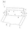
- FIG. 1 is a curtain applicator 1 shown for coating a running paper, cardboard or other fibrous web 2 with a liquid to pasty application medium. It includes, in addition to some not shown here units, such as air boundary layer control devices, start-stop-Auffang wornen or tubs, measuring equipment, feed lines, etc. above the fibrous web 2 and spaced therefrom arranged and only slightly hinted curtain application head 3.
- This gun 3 may be formed as a so-called Gleit harshdüse or slot nozzle and is machine width, so over the width of the fibrous web 2 reaching executed.
- the application head 3 can be designed both for a multi-layer application and for a single-layer application with which a single-layer or multi-layer curtain 4 can be produced.
- the curtain 4 drops from the tear-off edge 5 of the applicator head 3 substantially following the force of gravity down onto the fibrous web 2 and deposits on its surface as a coating layer AS.
- the curtain applicator 1 has a lateral, columnar trained edge guide element 6 respectively on the leader side FS and Drive side TS on.
- This edge guide element 6 serves to guide and also limit the size of the approximately 200 mm long single-layer or multi-layer curtain 4 between the tear-off edge 6 and the surface of the fibrous web 2 at its lateral edges 4a and 4b.
- the edge guide element 6 is adjustable in the width direction of the curtain 4, as the horizontal double arrows show. In the examples shown, the two edge guide elements 6 are within the width of the fibrous web 2, which is referred to as "inboard" -Fahrweise.
- FIG. 2 is the edge guide element 6 made FIG. 1 , seen from the side, shown in section. It can be seen that the edge guide element 6 has a cover plate 7 and a bottom plate 8.
- the edge guide element 6 consists of two superimposed, separate chambers 9 and 10, wherein the first chamber 9 is located above the second chamber 10.
- the first ie the upper chamber 9 has a fluid or liquid inlet 11 and the second, that is, the lower chamber 10 has a drain 12.
- Both nozzles or pipes for inlet 11 and outlet 12 point outwards.
- Both chambers 9 and 10 also have a wall 13 spanning them both. This wall 13 serves the actual guidance of the curtain and therefore contacted with their curtain side facing the respective curtain edge.
- FIG. 4 It is shown that the chambers 9 and 10 each have a U-shaped cross-section. It can also be seen that the wall 13 has been inserted with its drainage surface 18 in the open side of the U-section facing the curtain edge 4a .4b.
- overflow gap 15 and / or the suction opening 17 are adjustable in size.
- the overflow gap is about 10 to 20mm wide. Equally wide is the drainage surface 19 and the wall 13.
- the suction opening 17 is aligned dare and rectangular. It has a size of 1 x 5mm. In addition, this opening 17 is located directly above the bottom plate and is arranged centrally in the wall 13 parallel to the drain 12.
- Both chambers 9 and 10 of the edge guide element 6 are otherwise separated from each other by a transverse wall 20.
- water is preferably used as a fluid or liquid for the running fluid or liquid film 18, which is incidentally also controlled and regulated in its amount.
- water is preferably used.
- it is also a water / coating mixture or a mixture of water and surface-active substances, such as commercial surfactants used.
- FIG. 5 a circuit diagram is shown. This illustrates that the liquid discharged via the outlet 12 of the edge guide element 6 or the fluid or liquid film 18 is sucked to the outside and is fed via a line 21 to a separator 22.
- the solid-particle-containing liquid is discharged via a drain 23, while the "clean" liquid is sucked out of the separator 22 by means of a vacuum pump 24.
- This liquid is available as a renewed liquid feed for the edge guide element 6.
- a flow meter and control valve 25 the desired amount of fluid or liquid is fed via a line to the inlet 11 of the edge guide element.
Landscapes
- Coating Apparatus (AREA)
Abstract
Description
Die Erfindung betrifft ein Vorhang-Auftragswerk zur Beschichtung einer laufenden Papier-, Karton- oder anderen Faserstoffbahn, aufweisend einen oberhalb der Faserstoffbahn angeordneten und mindestens der Breite der Faserstoffbahn entsprechenden Vorhang-Auftragskopf zur Abgabe wenigstens eines flüssigen bis pastösen Auftragsmediums in Form eines ein- oder mehrschichtigen Vorhangs, der im Wesentlichen der Schwerkraft folgend auf die Faserstoffbahn herabfällt, wobei zur Führung des Vorhangs über seinen Fallweg hinweg, d.h. zwischen einer Abrisskante des Auftragskopfes und der Oberfläche der Faserstoffbahn an seinen beiden Rändern je ein Randführungselement vorgesehen ist, wobei das Randführungselement in Breitenrichtung des Vorhanges verstellbar ist.
Die Erfindung betrifft auch ein Verfahren zur Vorhangbeschichtung.The invention relates to a curtain applicator for coating a running paper, cardboard or other fibrous web, comprising a disposed above the fibrous web and at least the width of the fibrous web corresponding curtain applicator for dispensing at least one liquid to pasty application medium in the form of a on or multi-layer curtain, which falls substantially to gravity following the fibrous web, wherein for guiding the curtain across its fall away, ie between a spoiler edge of the applicator head and the surface of the fibrous web is provided at its two edges depending an edge guide element, wherein the edge guide element in the width direction the curtain is adjustable.
The invention also relates to a process for curtain coating.
Eine gattungsgemäße Vorrichtung und ein Verfahren ist beispielsweise aus der
Ebenfalls eine Vorrichtung und ein Verfahren sind aus der
Mit den bekannten Vorhang-Auftragswerken mehrere Auftragsmedien bzw. mehrere Schichten eines Auftragsmediums abgebbar. Eine Ausführungsart eines Vorhang-Auftragswerkes ist unter anderem aus der
Es sind aber auch andere Ausführungen von Auftragsköpfen bekannt, bei denen eine oder mehrere Schlitzdüsen nach unten in Richtung auf die darunter laufende Faserstoffbahn zeigen. Hierzu wird beispielsweise auf die
Beim Streichen - sowohl beim einschichtigen als auch mehrschichtigen Auftrag - mit dem Vorhang-Auftragswerk (Curtain Coater) kann die Beschichtungsbreite gleich oder auch kleiner als die Breite der Faserstoffbahn sein, was als "inboard"-Fahrweise bezeichnet wird.When painting - both single-layer and multi-layer application - with the Curtain Coater (curtain coater), the coating width can be equal to or less than the width of the fibrous web, which is referred to as "inboard" -Fahrweise.
Bei so genannter "overboard"-Fahrweise ist dagegen die Vorhangbreite größer als die Faserstoffbahnbreite.In the case of the so-called "overboard" approach, on the other hand, the curtain width is greater than the width of the fibrous web.
Insbesondere bei der inboard-Fahrweise sind Randführungselemente, wie sie in beiden erstgenannten Druckschriften offenbart sind, notwendig. Diese Randführungselemente führen den Vorhang, der ca. 200m lang ist, bis nahe an die Faserstoffbahn heran.In particular, in the inboard-driving edge management elements, as disclosed in the first two publications, necessary. These edge guide elements bring the curtain, which is about 200m long, close to the fibrous web.
In der Praxis werden derzeit säulenartige Randführungselemente aus porösem Material eingesetzt. Die als Gleitmittel dienende Fluid- bzw. Flüssigkeit bzw. Wasser ist seiner Menge noch undefiniert. Die verwendete Fluid- bzw. Flüssigkeit muss ständig laufen, weil sonst Verstopfungsgefahr droht. Die benötigte Fluid- bzw.In practice, columnar edge guide elements of porous material are currently used. The fluid or liquid or water serving as lubricant is still undefined in its quantity. The fluid or fluid used must run constantly, otherwise there is a risk of clogging. The required fluid or
Flüssigkeitsmenge ist dadurch enorm hoch und beträgt ca. 10 bis 15l/hThe amount of liquid is thus enormously high and is about 10 to 15l / h
Außerdem sind die Bauweisen der Randführungselemente (auch die in den genannten Druckschriften gezeigten Lösungen) kompliziert. Sie unterliegen einem hohen Verschleiß und lassen sich außerdem noch schlecht reinigen.In addition, the structures of the edge guide elements (including the solutions shown in the cited documents) are complicated. They are subject to high wear and can also be poorly cleaned.
Es ist daher Aufgabe der Erfindung, eine Vorrichtung und ein Verfahren anzugeben, bei denen die Nachteile des Standes der Technik nicht mehr auftreten.It is therefore an object of the invention to provide a device and a method in which the disadvantages of the prior art no longer occur.
Die Aufgabe der Erfindung wird mit einem Vorhang-Auftragswerk mit den Merkmalen des Anspruchs 1 gelöst.The object of the invention is achieved with a curtain applicator with the features of
Erfindungsgemäß ist vorgesehen, dass das Randführungselement eine Deckplatte und eine Bodenplatte aufweist und aus zwei übereinander angeordneten, separaten Kammern besteht, die jeweils einen U-förmigen Querschnitt aufweisen, wobei sich die erste Kammer oberhalb der zweiten Kammer befindet, die erste Kammer einen Fluid- bzw. Flüssigkeitszulauf und die zweite Kammer einen Fluid- bzw. Flüssigkeitsablauf aufweist und beide Kammern an ihrer zum jeweiligen Vorhangsrand zeigenden offenen Seite des U-Querschnittes mit einer durchgehenden Wand derart verschlossen sind, dass zum Einen zwischen Deckplatte und Oberkante der Wand ein sich in der ersten Kammer befindlicher Überlaufspalt verbleibt. Er dient zur Erzeugung eines Fluid- bzw. Flüssigkeitsfilmes, der den jeweiligen Vorhangsrand kontaktiert und dabei eine Ablauffläche der Wand herabläuft. Zum Anderen besteht auch zwischen der Unterkante der Außenwand und der Bodenplatte eine sich in der unteren, zweiten Kammer angeordnete, mittige Absaugöffnung, die mit dem Fluid- bzw. Flüssigkeitsablauf in Verbindung steht.According to the invention, the edge guide element has a cover plate and a bottom plate and consists of two superposed, separate chambers, each having a U-shaped cross section, wherein the first chamber is above the second chamber, the first chamber a fluid or Liquid inlet and the second chamber has a fluid or liquid drain and both chambers are closed at their respective edge of the curtain facing open side of the U-section with a continuous wall such that on the one between the cover plate and the upper edge of the wall in the first Chamber located overflow gap remains. It serves to produce a fluid or liquid film which contacts the respective curtain edge and thereby runs down a drainage surface of the wall. On the other hand, there is also between the lower edge of the outer wall and the bottom plate arranged in the lower, second chamber, central suction opening, which is in communication with the fluid or liquid drain.
Das erfindungsgemäße Randführungselement und damit auch das Vorhang-Auftragswerk zeichnen sich durch eine einfache Bauweise aus. Zur Führung des Vorhangs wird nur eine geringe Fluid- bzw. Flüssigkeitsmenge benötigt. Die unerwünschten Farbwülste an den Rändern der Oberfläche der Faserstoffbahn werden durch die einwandfreie Führung des Vorhangs und ohne dass der Vorhang eingeschnürt wird, vermieden.The edge guide element according to the invention and thus also the curtain applicator are characterized by a simple construction. To guide the curtain only a small amount of fluid or liquid is needed. The unwanted color beads at the edges of the surface of the fibrous web are caused by the proper guidance of the curtain and without the curtain is constricted, avoided.
Das Randführungselement, insbesondere seine den betreffenden Vorhangsrand kontaktierende Ablauffläche lässt sich aufgrund seiner/ihrer einfachen Bauweise leicht reinigen.The edge guide element, in particular its drainage surface contacting the relevant curtain edge, can be easily cleaned due to its simple construction.
Vereinfacht wird die Reinigungsarbeit, aber auch das Ablaufverhalten, wenn die Ablauffläche aus Edelstahl oder Aluminium besteht. Vorteilhaft ist es, wenn diese Fläche poliert ist bzw. einen Rauigkeitswert Ra von 0,8 bis 1,0 aufweist. Die Ablauffläche kann allerdings auch aus Kunststoff, insbesondere Teflon gefertigt sein, welches ein gutes Ablaufverhalten zeigt.Simplified is the cleaning work, but also the drainage behavior, if the drainage surface made of stainless steel or aluminum. It is advantageous if this surface is polished or has a roughness value Ra of 0.8 to 1.0. However, the drainage surface may also be made of plastic, in particular Teflon, which shows a good flow behavior.
Hinsichtlich einer variabel einzustellenden Fließmenge des zur Führung bzw. besseren Gleitfähigkeit des Auftragsmediumsvorhangs dienenden Fluid- bzw. Flüssigkeitsfilmes ist es vorteilhaft, wenn der sich in der ersten Kammer befindliche Überlaufspalt und/oder die in der unteren, zweiten Kammer angeordnete Absaugöffnung jeweils in ihrer Größe verstellen lassen.With regard to a variable amount of flow to be used for guiding or better lubricity of the Auftragmediumsvorhangs fluid or liquid film, it is advantageous if the located in the first chamber overflow gap and / or arranged in the lower, second chamber suction respectively adjusted in size to let.
Vorteilhaft ist es, wenn die Absaugöffnung mittig in der Ablaufwand angeordnet ist und parallel dem Fluid- bzw. Flüssigkeitsabzug gegenübersteht. Der Abzug der Fluid- bzw. Flüssigkeit, welches mit Streichfarbenpartikeln und möglicherweise Abriebteilchen behaftet ist, kann dadurch rückstandsfrei erfolgen.It is advantageous if the suction opening is arranged centrally in the drain wall and parallel to the fluid or liquid withdrawal faces. The deduction of the fluid or liquid, which is associated with coating color particles and possibly abrasion particles, can be done without residue.
Als Fluid- bzw. Flüssigkeit für den ablaufenden Fluid- bzw. Flüssigkeitsfilm ist vorzugsweise Wasser vorgesehen. Es kann aber alternativ auch ein Wasser/ Streichfarbengemisch oder hinsichtlich der Sauberhaltung der Ablauffläche auch ein Gemisch, welches oberflächenaktive Substanzen, wie handelsübliche Tenside enthält, Verwendung finden.As fluid or liquid for the running fluid or liquid film preferably water is provided. Alternatively, however, it is also possible to use a water / coating mixture or, with regard to keeping the drainage surface clean, a mixture which contains surface-active substances, such as commercially available surfactants.
Die Absaugöffnung für die abzuführende Fluid- bzw. Flüssigkeit ist ca. 1 x 5mm groß. Diese Absaugöffnung kann sowohl senkrecht, als auch waagerecht in die Ablaufwand eingearbeitet sein. Denkbar wären allerdings auch andere Öffnungsgeometrien, beispielsweise kreisrunde Öffnungen. Alternierend kann in der Bodenplatte ein seitlicher Schlitz für eine Absaugung oder auch zusätzlich noch ein Absatz eingearbeitet sein.The suction opening for the discharged fluid or liquid is about 1 x 5mm in size. This suction opening can be incorporated both vertically and horizontally in the drain wall. Conceivable, however, would be other opening geometries, for example, circular openings. Alternately, in the bottom plate, a lateral slot for a suction or in addition still a paragraph be incorporated.
Der besagte Überlaufspalt in der oberen Kammer ist ca. 10 bis 20 mm breit.The said overflow gap in the upper chamber is about 10 to 20 mm wide.
Vorteilhaft ist es außerdem, wenn die Bodenplatte des Randführungselementes schräg ausgebildet ist, so dass die Schräge an den Verlauf einer ebenfalls schräg laufenden Faserstoffbahn angepasst ist. Dabei ist es denkbar, dass sich die Bodenplatte in einem gewünschten Winkel verstellen läst. Damit hat man die Möglichkeit, das Randführelement, welches ja sehr nah an die darunter laufende Faserstoffbahn heranreichen soll, sowohl für horizontal, als auch schräg in aufwärtige oder in abwärtige Richtung laufende Faserstoffbahnen einzusetzen. Denkbar sind natürlich auch auf Vorrat gefertigte Randführungselemente mit verschieden ausgebildeten bzw. in verschiedenen Winkeln abgeschrägten Bodenplatten.It is also advantageous if the bottom plate of the edge guide element is formed obliquely, so that the slope is adapted to the course of a likewise obliquely running fibrous web. It is conceivable that the bottom plate can be adjusted at a desired angle. This gives you the opportunity to use the edge guiding element, which is supposed to be very close to the fibrous web running underneath, both for horizontal, as well as obliquely in upwardly or downwardly running fibrous webs. Conceivable, of course, are also made on stock edge guide elements with differently shaped or slanted at different angles floor panels.
Die Aufgabe der Erfindung wird auch mit einem Verfahren gemäß Anspruch 11 gelöst. Das Verfahren dient zur Beschichtung einer laufenden Papier-, Karton- oder anderen Faserstoffbahn während ihrer Beschichtung innerhalb eines Herstellungs- bzw. Veredelungsprozesses der Faserstoffbahn mit wenigstens einem flüssigen bis pastösen Auftragsmedium, welches in Form eines ein- oder mehrschichtigen Vorhangs, der im Wesentlichen der Schwerkraft folgend frei fallend von oben her auf die Faserstoffbahn aufgebracht wird. Dabei wird der Vorhang über seinen Fallweg hinweg zwischen einer Abrisskante und der Oberfläche der Faserstoffbahn jeweils an seinem seitlichen Rand mit je einem Randführungselement geführt. Die Breite des Vorhangs kann durch Verschiebung des Randführungselementes in Querrichtung eingestellt werden.The object of the invention is also achieved by a method according to
Vorzugsweise ist vorgesehen, dass eine Vorhangsbreite eingestellt wird, die geringer als die Breite der Faserstoffbahn ist. Dadurch wird das Vorhangstreichen in so genannter "inboard-Fahrweise betrieben. Dies ermöglicht einen besser als bisher geführten Vorhang. Gleichzeitig wird dadurch auch die Qualität des Auftrages erhöht, wodurch die Druckeigenschaften des beispielsweise hergestellten Papiers oder Kartons steigen.It is preferably provided that a curtain width is set which is smaller than the width of the fibrous web. As a result, the curtain coating is operated in so-called "inboard" mode of operation, which allows for a better-than-previously-executed curtain and, at the same time, increases the quality of the order. whereby the printing properties of the paper or cardboard produced, for example, increase.
Erfindungsgemäß ist vorgesehen, dass zur Führung des Vorhangs dem Randführungselement ein Fluid- bzw. eine Flüssigkeit zugeführt wird. Dieses zugeführte Fluid wird in der ersten Kammer des Randführungselementes nach oben geführt und durch einen schmalen Überlaufspalt geleitet. Danach fließt das Fluid- bzw. die Flüssigkeit über eine Ablauffläche des Randführungselementes nach unten und von da aus nach außen.It is provided according to the invention that a fluid or a liquid is supplied to the edge guide element for guiding the curtain. This supplied fluid is guided in the first chamber of the edge guide element upwards and passed through a narrow overflow gap. Thereafter, the fluid or the liquid flows down over a drain surface of the edge guide element and from there to the outside.
Auf der Ablauffläche wird mit Hilfe des schmalen Überlaufspaltes ein dünner Fluid- bzw. Flüssigkeitsfilm gebildet und dadurch der Vorhangsrand sehr gut geführt. Die gefürchteten Farbwülste auf der Faserstoffbahn und dadurch weitergehende Verschmutzungen auf bahnführenden Bauteilen oder nasse Bahnränder entstehen dadurch nicht.On the drainage surface, a thin fluid or liquid film is formed with the help of the narrow overflow gap, thereby guiding the curtain edge very well. The dreaded color beads on the fibrous web and thereby further contamination on web-leading components or wet web edges do not arise.
Die Wirtschaftlichkeit des Verfahrens lässt sich erhöhen, wenn die über einen Ablauf abgeführte Flüssigkeit bzw. der Fluid- bzw. Flüssigkeitsfilm abgesaugt, einem Abscheider zugeführt und danach mittels einer Vakuumpumpe im Kreislauf dem Fluid- bzw. Flüssigkeitszulauf des Randführungselementes wieder zugeführt wird.The economy of the method can be increased if the drained via a drain liquid or the fluid or liquid film, fed to a separator and then fed by a vacuum pump in the circuit to the fluid or liquid feed of the edge guide element.
Wichtig ist, dass nur ca. 2l/h des Fluid- bzw. Flüssigkeitsfilmes die Ablauffläche des Randführungselementes hinabfließen. Diese gegenüber dem Stand der Technik sehr geringe Menge ist in überraschender Weise zur einwandfreien Führung des Vorhangs völlig ausreichend.It is important that only about 2l / h of fluid or liquid film flow down the drainage surface of the edge guide element. This compared to the prior art very small amount is completely sufficient for the perfect guidance of the curtain in a surprising manner.
Das Verfahren lässt sich überdies sehr effektiv gestalten, wenn die Menge des Fluid- bzw. Flüssigkeitsfilmes gesteuert und/oder geregelt wird.Moreover, the method can be made very effective if the amount of fluid film is controlled and / or regulated.
Die erfindungsgemäßen Randführungsleisten lassen sich sehr einfach auch nachträglich in bestehende Vorhangstreichanlagen einbauen. Dabei ist die Anwendung verschiedener Ausführungsformen eines den Vorhang abgebenden Vorhang-Auftragskopfes, wie z.B. Gleitschichtdüse oder Schlitzdüse sowie bei einschichtig oder auch mehrschichtig ausgebildetem Vorhang möglich.
Nachfolgend wird die Erfindung anhand eines Ausführungsbeispieles näher erläutert. Es zeigen in schematischer Darstellung:
- Figur 1:
- ein erfindungsgemäßes Vorhang-Auftragwerk mit Randführungselementen in schematischer perspektivischer Darstellung
- Figur 2:
- einen Längsschnitt durch ein erfindungsgemäßes Randführungselement aus
Figur 1 , von der Seite ausgesehen, - Figur 3:
- einen Längsschnitt durch ein erfindungsgemäßes Randführungselement aus
Figur 1 , von vorn gesehen, - Figur 4:
- einen Querschnitt durch das Randführungselement gem.
Figur 3 - Figur 5:
- ein Flüssigkeitskreislauf-Schema für das Vorhang-Auftragswerk gem.
Figur 1
The invention will be explained in more detail with reference to an embodiment. In a schematic representation:
- FIG. 1:
- an inventive curtain applicator with edge guide elements in a schematic perspective view
- FIG. 2:
- a longitudinal section through an inventive edge guide element
FIG. 1 , viewed from the side, - FIG. 3:
- a longitudinal section through an inventive edge guide element
FIG. 1 , seen from the front, - FIG. 4:
- a cross section through the edge guide element acc.
FIG. 3 . - FIG. 5:
- a liquid circulation scheme for the curtain applicator acc.
FIG. 1
In der
Wie aus
Die Randführungselement 6 ist in Breitenrichtung des Vorhanges 4 verstellbar, wie die waagerechten Doppelpfeile zeigen. Im gezeigten Beispielen befinden sich die beiden Randführungselemente 6 innerhalb der Breite der Faserstoffbahn 2, was als "inboard"-Fahrweise bezeichnet wird.The
In
In
Wie in beiden
In
Die Ablauffläche 19 der Wand 13 besteht im Beispiel aus Edelstahl mit einem Rauigkeitswert Ra= 0,8-1,0, was sich hinsichtlich Verschmutzung der Ablauffläche 19 und Ablaufverhalten des Filmes sehr positiv auswirkt.The
Zu erwähnen ist noch, dass der Überlaufspalt 15 und/oder die Absaugöffnung 17 in ihrer Größe verstellbar sind. Der Überlaufspalt ist ca. 10- 20mm breit. Ebenso breit ist auch die Ablauffläche 19 bzw. die Wand 13.It should also be mentioned that the
Im Beispiel ist die Absaugöffnung 17 wagerecht ausgerichtet und rechteckig gestaltet. Sie weist eine Größe von 1 x 5mm auf. Außerdem befindet sich diese Öffnung 17 unmittelbar oberhalb der Bodenplatte und ist mittig in der Wand 13 parallel zum Ablauf 12 angeordnet.In the example, the
Beide Kammern 9 und 10 des Randführungselements 6 sind im Übrigen durch eine Querwand 20 voneinander getrennt.Both
Als Fluid- bzw. Flüssigkeit für den ablaufenden Fluid- bzw. Flüssigkeitsfilm 18, der in seiner Menge übrigens auch steuer- und regelbar ist, wird vorzugsweise Wasser verwendet. Es ist aber auch ein Wasser/Streichfarbengemisch oder ein Gemisch aus Wasser und oberflächenaktiven Substanzen, wie handelsübliche Tenside verwendbar.As a fluid or liquid for the running fluid or
Mit dem erfindungsgemäßen Randführungselement 6 wird eine Vorhangsbreite eingestellt, die geringer als die Breite der Faserstoffbahn 2 ist.With the
In
- 11
- Vorhang-AuftragswerkCurtain applicator
- 22
- FaserstoffbahnFibrous web
- 33
- Vorhang-AuftragskopfCurtain applicator head
- 44
- Vorhangcurtain
- 4a, 4b4a, 4b
- seitlicher Vorhangrandlateral curtain edge
- 55
- Abrisskantetear-off edge
- 66
- RandführungselementEdge guide element
- 77
- Deckplattecover plate
- 88th
- Bodenplattebaseplate
- 99
- erste Kammerfirst chamber
- 1010
- zweite Kammersecond chamber
- 1111
- Fluid- bzw. FlüssigkeitszulaufFluid or liquid feed
- 1212
- Ablaufprocedure
- 1313
- Wandwall
- 1414
- Oberkantetop edge
- 1515
- ÜberlaufspaltOverflow gap
- 1616
- Unterkantelower edge
- 1717
- Absaugöffnungsuction
- 1818
- Fluid- bzw. FlüssigkeitsfilmFluid or liquid film
- 1919
- Ablaufflächedrainage area
- 2020
- Querwandpartition
- 2121
- Leitungmanagement
- 2222
- Abscheiderseparators
- 2323
- Ablaufprocedure
- 2424
- Vakuumpumpevacuum pump
- 2525
- Regelventilcontrol valve
- LL
- Längsrichtunglongitudinal direction
- MM
- Auftragsmediumapplication medium
- FSFS
- Führerseitetender side
- TSTS
- Triebseitedrive side
Claims (15)
dadurch gekennzeichnet, dass
das Randführungselement (6) eine Deckplatte (7) und eine Bodenplatte (8) aufweist und aus zwei übereinander angeordneten, separaten Kammern (9, 10) besteht, wobei sich die erste Kammer (9) oberhalb der zweiten Kammer (10) befindet, die erste Kammer (9) einen Fluid- bzw. Flüssigkeitszulauf (11) und die zweite Kammer (10) einen Ablauf (12) aufweist und beide Kammern (9, 10) derart mit einer Wand (13) verschlossen sind, dass nur zwischen Deckplatte (7) und Oberkante (14) der Wand (13) ein zur ersten Kammer (9) gehörender Überlaufspalt (15) zur Erzeugung eines Fluid- bzw. Flüssigkeitsfilmes (18) sowie zwischen der Unterkante (16) der Wand (13) und der Bodenplatte (8) eine in der unteren, zweiten Kammer (10) angeordnete Absaugöffnung (17) verbleibt und die Wand (13) an ihrer zum jeweiligen Vorhangsrand (4a, 4b) zeigenden Seite eine Ablauffläche (19) für den Fluid- bzw. Flüssigkeitsfilm (18) aufweist.Curtain coater (1) for coating a running paper, board or other fibrous web (2), comprising a curtain applicator head (3) disposed above the fibrous web (2) and at least the width of the fibrous web (2) for dispensing at least a liquid to pasty application medium (M) in the form of a single- or multi-layer curtain (4), which falls substantially to gravity following the fibrous web (2), wherein for guiding the curtain (4) across its fall away, ie between a Tear-off edge (5) of the application head (3) and the surface of the fibrous web (2) at its two edges (4a, 4b) per an edge guide element (6) is provided, wherein the edge guide element (6), if desired in the width direction of the curtain (4) adjustable is
characterized in that
the edge guide element (6) has a cover plate (7) and a bottom plate (8) and consists of two separate chambers (9, 10) arranged one above the other, the first chamber (9) being located above the second chamber (10) first chamber (9) has a fluid or liquid inlet (11) and the second chamber (10) has a drain (12) and both chambers (9, 10) are closed with a wall (13) such that only between cover plate ( 7) and upper edge (14) of the wall (13) to the first chamber (9) belonging overflow gap (15) for generating a fluid or liquid film (18) and between the lower edge (16) of the wall (13) and the bottom plate (8) a suction opening (17) arranged in the lower, second chamber (10) remains and the wall (13) at its side facing the respective curtain edge (4a, 4b) has a drainage surface (19) for the fluid or liquid film (FIG. 18).
dadurch gekennzeichnet, dass
die erste Kammer (9) und die zweite Kammer (10) jeweils einen U-förmigen Querschnitt aufweist, wobei in die offene Seite des U- förmigen Querschnittes die Wand (13) eingelassen ist.Curtain coater according to claim 1,
characterized in that
the first chamber (9) and the second chamber (10) each have a U-shaped Cross-section, wherein in the open side of the U-shaped cross section, the wall (13) is embedded.
dadurch gekennzeichnet, dass
die erste Kammer (9) und die zweite Kammer (10) durch eine Querwand (20) voneinander getrennt sind.Curtain coater according to claim 1 or 2,
characterized in that
the first chamber (9) and the second chamber (10) are separated from each other by a transverse wall (20).
dadurch gekennzeichnet, dass
die Ablauffläche (19) der Wand (13) poliert ist und aus einem Werkstoff, wie Edelstahl oder Aluminium oder einem Kunststoff, wie Teflon besteht.Curtain coater according to one of claims 1 or 2,
characterized in that
the drainage surface (19) of the wall (13) is polished and made of a material such as stainless steel or aluminum or a plastic such as Teflon.
dadurch gekennzeichnet, dass
die Ablauffläche (19) eine Rauigkeit Ra von ca. 0,8 bis 1,0 aufweist.Curtain coater according to claim 4,
characterized in that
the drainage surface (19) has a roughness Ra of approximately 0.8 to 1.0.
dadurch gekennzeichnet, dass
der Überlaufspalt (15) und/oder die Absaugöffnung (17) in ihrer Größe verstellbar sind.Curtain coater according to one of claims 1 to 5,
characterized in that
the overflow gap (15) and / or the suction opening (17) are adjustable in size.
dadurch gekennzeichnet, dass
sich die Absaugöffnung (17) mittig in der Wand (13) und unmittelbar oberhalb der Bodenplatte (8) befindet.Curtain coater according to one of claims 1 to 6,
characterized in that
the suction opening (17) is located centrally in the wall (13) and immediately above the bottom plate (8).
dadurch gekennzeichnet, dass
als Fluid- bzw. Flüssigkeit für den ablaufenden Fluid- bzw. Flüssigkeitsfilm (18) vorzugsweise Wasser, aber auch ein Wasser/Streichfarbengemisch oder ein Gemisch aus Wasser und oberflächenaktiven Substanzen, wie handelsübliche Tenside, verwendbar sind.Curtain coater according to one of claims 1 to 7,
characterized in that
as fluid or liquid for the running fluid or liquid film (18) preferably water, but also a water / coating mixture or a mixture of water and surface-active substances, such as commercial Surfactants, are usable.
dadurch gekennzeichnet, dass
die Absaugöffnung (17) ca. 1 x 5mm groß ist und senkrecht oder waagerecht in die Wand (13) eingearbeitet ist.Curtain coater according to one of the preceding claims,
characterized in that
the suction opening (17) is about 1 x 5mm in size and is incorporated vertically or horizontally in the wall (13).
dadurch gekennzeichnet, dass
der Überlaufspalt (15) und auch die Ablauffläche (19) 10 bis 20mm breit sind.Curtain coater according to one of the preceding claims,
characterized in that
the overflow gap (15) and the drainage surface (19) are 10 to 20mm wide.
dadurch gekennzeichnet, dass
zur Führung des Vorhangs (4) dem Randführungselement (6) eine Fluid- bzw. Flüssigkeit zugeführt wird, die einen Fluid- bzw. Flüssigkeitsfilm (18) bildend über eine Ablauffläche (19) des Randführungselementes (6) geleitet und anschließend abgeführt wird.Process for coating a running paper, board or other fibrous web (2) during its coating within a manufacturing or finishing process of the fibrous web (2) with at least one liquid to pasty application medium, which in the form of a single or multilayer curtain (4 ), which is applied substantially free falling from above on the fibrous web (2) following the gravity, wherein the curtain (4) across its fall path between a trailing edge (5) and the surface of the fibrous web (2) each at its lateral Edge (4a, 4b) is guided with one edge guide element (6), wherein the width of the curtain (4) is adjusted by displacement of the edge guide element (6) in the transverse direction,
characterized in that
for guiding the curtain (4) to the edge guide element (6) a fluid or liquid is supplied, which is a fluid or liquid film (18) forming a discharge surface (19) of the edge guide element (6) passed and then discharged.
dadurch gekennzeichnet, dass
die über einen Fluid- bzw. Flüssigkeitsablauf (12) abgeführte Fluid- bzw. Flüssigkeit bzw. der Fluid- bzw. Flüssigkeitsfilm (18) abgesaugt, einem Abscheider (22) zugeführt und danach mittels einer Vakuumpumpe (24) abgezogen und gewünschtenfalls dem Fluid- bzw. Flüssigkeitszulauf (11) des Randführungselementes (6) wieder zugeführt wird.Method according to claim 11,
characterized in that
the liquid or liquid or the fluid or liquid film (18) discharged via a fluid or liquid outlet (12) is sucked off Separator (22) is supplied and then withdrawn by means of a vacuum pump (24) and, if desired, the fluid or liquid inlet (11) of the edge guide element (6) is fed again.
dadurch gekennzeichnet, dass
der Fluid- bzw. Flüssigkeitsfilm (18) die Ablauffläche (19) des Randführungselementes (6) in einer Menge von ca. 2l/h hinabfließt.Method according to claim 11 or 12,
characterized in that
the fluid or liquid film (18) flows down the run-off surface (19) of the edge guide element (6) in an amount of approximately 2 l / h.
dadurch gekennzeichnet, dass
die Menge des Fluid- bzw. Flüssigkeitsfilmes (18) gesteuert und/oder geregelt wird.Method according to one of claims 11 to 13,
characterized in that
the amount of fluid or liquid film (18) is controlled and / or regulated.
dadurch gekennzeichnet, dass
eine Vorhangsbreite eingestellt wird, die geringer als die Breite der Faserstoffbahn (2) ist.Method according to one of claims 11 to 14,
characterized in that
a curtain width is set which is smaller than the width of the fibrous web (2).
Applications Claiming Priority (1)
| Application Number | Priority Date | Filing Date | Title |
|---|---|---|---|
| DE102008054892A DE102008054892A1 (en) | 2008-12-18 | 2008-12-18 | Curtain applicator |
Publications (2)
| Publication Number | Publication Date |
|---|---|
| EP2198975A1 true EP2198975A1 (en) | 2010-06-23 |
| EP2198975B1 EP2198975B1 (en) | 2012-05-02 |
Family
ID=41566261
Family Applications (1)
| Application Number | Title | Priority Date | Filing Date |
|---|---|---|---|
| EP09178315A Not-in-force EP2198975B1 (en) | 2008-12-18 | 2009-12-08 | Curtain application unit |
Country Status (3)
| Country | Link |
|---|---|
| EP (1) | EP2198975B1 (en) |
| AT (1) | ATE555858T1 (en) |
| DE (1) | DE102008054892A1 (en) |
Cited By (1)
| Publication number | Priority date | Publication date | Assignee | Title |
|---|---|---|---|---|
| EP3180475B1 (en) | 2014-08-15 | 2018-10-10 | Voith Patent GmbH | Coating device |
Families Citing this family (1)
| Publication number | Priority date | Publication date | Assignee | Title |
|---|---|---|---|---|
| DE102010031576A1 (en) | 2010-07-20 | 2012-01-26 | Voith Patent Gmbh | Curtain applicator |
Citations (5)
| Publication number | Priority date | Publication date | Assignee | Title |
|---|---|---|---|---|
| US5390900A (en) * | 1994-04-26 | 1995-02-21 | Int Rolling Mill Consultants | Metal strip cooling system |
| EP0907103A1 (en) * | 1997-10-03 | 1999-04-07 | Troller Schweizer Engineering AG | Process and apparatus for curtain coating a moving substrate |
| DE10117668A1 (en) * | 2001-04-09 | 2002-10-10 | Bachofen & Meier Ag Buelach | Device for coating a running material web |
| DE102004056270A1 (en) * | 2004-11-22 | 2006-05-24 | Basf Ag | Side guide for the curtain coating |
| DE102008045576A1 (en) * | 2007-10-17 | 2009-04-23 | Metso Paper, Inc. | Edge guide for adjusting a coating curtain that consists of a web to be coated on impact point in a curtain coating process, comprises a suction slot arranged in the area of its discharge edge |
Family Cites Families (5)
| Publication number | Priority date | Publication date | Assignee | Title |
|---|---|---|---|---|
| DE19735588A1 (en) | 1997-04-21 | 1999-02-18 | Jagenberg Papiertech Gmbh | Coating a moving web |
| SE515824C2 (en) | 2000-01-26 | 2001-10-15 | Tetra Laval Holdings & Finance | Method for manufacturing a multilayered packaging laminate by wet coating, as well as laminates made according to the procedure |
| DE10012344A1 (en) | 2000-03-14 | 2001-09-20 | Voith Paper Patent Gmbh | Continuous liquid curtain coating, for paper or card operates under specified conditions of temperature, pressure and viscosity, leaving thin wet film on surface |
| DE10232949A1 (en) | 2002-07-19 | 2004-01-29 | Voith Paper Patent Gmbh | Web coating curtain applicator, for wide paper/cardboard webs moving at high speeds, has side guides with jet openings to stabilize the falling curtain coating to give a consistent edge coating application |
| DE10359117A1 (en) | 2003-12-17 | 2005-07-28 | Voith Paper Patent Gmbh | Curtain applicator unit |
-
2008
- 2008-12-18 DE DE102008054892A patent/DE102008054892A1/en not_active Withdrawn
-
2009
- 2009-12-08 AT AT09178315T patent/ATE555858T1/en active
- 2009-12-08 EP EP09178315A patent/EP2198975B1/en not_active Not-in-force
Patent Citations (5)
| Publication number | Priority date | Publication date | Assignee | Title |
|---|---|---|---|---|
| US5390900A (en) * | 1994-04-26 | 1995-02-21 | Int Rolling Mill Consultants | Metal strip cooling system |
| EP0907103A1 (en) * | 1997-10-03 | 1999-04-07 | Troller Schweizer Engineering AG | Process and apparatus for curtain coating a moving substrate |
| DE10117668A1 (en) * | 2001-04-09 | 2002-10-10 | Bachofen & Meier Ag Buelach | Device for coating a running material web |
| DE102004056270A1 (en) * | 2004-11-22 | 2006-05-24 | Basf Ag | Side guide for the curtain coating |
| DE102008045576A1 (en) * | 2007-10-17 | 2009-04-23 | Metso Paper, Inc. | Edge guide for adjusting a coating curtain that consists of a web to be coated on impact point in a curtain coating process, comprises a suction slot arranged in the area of its discharge edge |
Cited By (1)
| Publication number | Priority date | Publication date | Assignee | Title |
|---|---|---|---|---|
| EP3180475B1 (en) | 2014-08-15 | 2018-10-10 | Voith Patent GmbH | Coating device |
Also Published As
| Publication number | Publication date |
|---|---|
| ATE555858T1 (en) | 2012-05-15 |
| DE102008054892A1 (en) | 2010-06-24 |
| EP2198975B1 (en) | 2012-05-02 |
Similar Documents
| Publication | Publication Date | Title |
|---|---|---|
| EP3976378A1 (en) | Printhead cleaning device for a 3d printer, 3d printer comprising a printhead cleaning device, use of the printhead cleaning device and method for cleaning a printhead of a 3d printer | |
| DE202017100655U1 (en) | Apparatus for treating fibrous webs | |
| DE102008040403A1 (en) | Curtain applicator | |
| EP2198975B1 (en) | Curtain application unit | |
| EP1198643B1 (en) | Application device | |
| DE102005035317A1 (en) | Method for directly applying layers of a liquid-to-pasty medium to a paper, cardboard or other fibrous strip comprises releasing the media separately from one another from chambers and combining to form a curtain | |
| EP2379230A1 (en) | Curtain applicator | |
| DE102006052687A1 (en) | Multiple coating of a moving web, of paper/cardboard, uses a slide die applicator for the under coating and a curtain coater with a different medium for the upper coating | |
| EP2067531A2 (en) | Edge guide | |
| EP2596171B1 (en) | Curtain applicator | |
| EP2014376A2 (en) | Curtain coating machine | |
| EP2172592B1 (en) | Curtain application device | |
| EP2409781B1 (en) | Curtain coating apparatus | |
| DE102008040409A1 (en) | Curtain-coating unit for coating a moving paper, cardboard or other fiber web with fluid to pasty coating medium in the form of one or more layered curtain, comprises a curtain coating head arranged over the fiber material web | |
| EP2111925A1 (en) | Curtain application device | |
| DE102022105518B4 (en) | Application nozzle, application mechanism and process | |
| DE102022105510B4 (en) | Application nozzle, application mechanism and process | |
| EP2083119B1 (en) | Curtain application device | |
| EP1521643A1 (en) | Coating head | |
| EP2070600A2 (en) | Method for coating a running web of paper, cardboard or another fibrous material using curtain coating | |
| DE102008042522A1 (en) | Curtain coating tool for coating a running paper-, cardboard or other fiber material web with a fluid to pasty coating medium, comprises a curtain coating head arranged above the fiber material web, and a coating medium chamber | |
| EP2379231A1 (en) | Curtain applicator | |
| DE102008040407A1 (en) | Curtain-coating unit for coating a moving paper, cardboard or other fiber web with fluid to pasty coating medium in the form of one or more layered curtain, comprises a curtain coating head arranged over the fiber material web | |
| EP1947241A1 (en) | Method for curtain coating | |
| DE10359112A1 (en) | System to clean a curtain coater jet, to apply a liquid coating to a moving wet/dry web, uses pulses at a higher pressure level on the coating medium at regular intervals |
Legal Events
| Date | Code | Title | Description |
|---|---|---|---|
| PUAI | Public reference made under article 153(3) epc to a published international application that has entered the european phase |
Free format text: ORIGINAL CODE: 0009012 |
|
| AK | Designated contracting states |
Kind code of ref document: A1 Designated state(s): AT BE BG CH CY CZ DE DK EE ES FI FR GB GR HR HU IE IS IT LI LT LU LV MC MK MT NL NO PL PT RO SE SI SK SM TR |
|
| AX | Request for extension of the european patent |
Extension state: AL BA RS |
|
| 17P | Request for examination filed |
Effective date: 20101223 |
|
| 17Q | First examination report despatched |
Effective date: 20110120 |
|
| GRAP | Despatch of communication of intention to grant a patent |
Free format text: ORIGINAL CODE: EPIDOSNIGR1 |
|
| RIC1 | Information provided on ipc code assigned before grant |
Ipc: B05C 5/00 20060101AFI20111021BHEP |
|
| GRAS | Grant fee paid |
Free format text: ORIGINAL CODE: EPIDOSNIGR3 |
|
| GRAA | (expected) grant |
Free format text: ORIGINAL CODE: 0009210 |
|
| AK | Designated contracting states |
Kind code of ref document: B1 Designated state(s): AT BE BG CH CY CZ DE DK EE ES FI FR GB GR HR HU IE IS IT LI LT LU LV MC MK MT NL NO PL PT RO SE SI SK SM TR |
|
| REG | Reference to a national code |
Ref country code: GB Ref legal event code: FG4D Free format text: NOT ENGLISH |
|
| REG | Reference to a national code |
Ref country code: AT Ref legal event code: REF Ref document number: 555858 Country of ref document: AT Kind code of ref document: T Effective date: 20120515 Ref country code: CH Ref legal event code: EP |
|
| REG | Reference to a national code |
Ref country code: IE Ref legal event code: FG4D Free format text: LANGUAGE OF EP DOCUMENT: GERMAN |
|
| REG | Reference to a national code |
Ref country code: DE Ref legal event code: R096 Ref document number: 502009003453 Country of ref document: DE Effective date: 20120621 |
|
| REG | Reference to a national code |
Ref country code: NL Ref legal event code: VDEP Effective date: 20120502 |
|
| REG | Reference to a national code |
Ref country code: LT Ref legal event code: MG4D Effective date: 20120502 |
|
| PG25 | Lapsed in a contracting state [announced via postgrant information from national office to epo] |
Ref country code: CY Free format text: LAPSE BECAUSE OF FAILURE TO SUBMIT A TRANSLATION OF THE DESCRIPTION OR TO PAY THE FEE WITHIN THE PRESCRIBED TIME-LIMIT Effective date: 20120502 Ref country code: LT Free format text: LAPSE BECAUSE OF FAILURE TO SUBMIT A TRANSLATION OF THE DESCRIPTION OR TO PAY THE FEE WITHIN THE PRESCRIBED TIME-LIMIT Effective date: 20120502 Ref country code: IS Free format text: LAPSE BECAUSE OF FAILURE TO SUBMIT A TRANSLATION OF THE DESCRIPTION OR TO PAY THE FEE WITHIN THE PRESCRIBED TIME-LIMIT Effective date: 20120902 Ref country code: NO Free format text: LAPSE BECAUSE OF FAILURE TO SUBMIT A TRANSLATION OF THE DESCRIPTION OR TO PAY THE FEE WITHIN THE PRESCRIBED TIME-LIMIT Effective date: 20120802 Ref country code: SE Free format text: LAPSE BECAUSE OF FAILURE TO SUBMIT A TRANSLATION OF THE DESCRIPTION OR TO PAY THE FEE WITHIN THE PRESCRIBED TIME-LIMIT Effective date: 20120502 Ref country code: PL Free format text: LAPSE BECAUSE OF FAILURE TO SUBMIT A TRANSLATION OF THE DESCRIPTION OR TO PAY THE FEE WITHIN THE PRESCRIBED TIME-LIMIT Effective date: 20120502 |
|
| PG25 | Lapsed in a contracting state [announced via postgrant information from national office to epo] |
Ref country code: PT Free format text: LAPSE BECAUSE OF FAILURE TO SUBMIT A TRANSLATION OF THE DESCRIPTION OR TO PAY THE FEE WITHIN THE PRESCRIBED TIME-LIMIT Effective date: 20120903 Ref country code: HR Free format text: LAPSE BECAUSE OF FAILURE TO SUBMIT A TRANSLATION OF THE DESCRIPTION OR TO PAY THE FEE WITHIN THE PRESCRIBED TIME-LIMIT Effective date: 20120502 Ref country code: LV Free format text: LAPSE BECAUSE OF FAILURE TO SUBMIT A TRANSLATION OF THE DESCRIPTION OR TO PAY THE FEE WITHIN THE PRESCRIBED TIME-LIMIT Effective date: 20120502 Ref country code: GR Free format text: LAPSE BECAUSE OF FAILURE TO SUBMIT A TRANSLATION OF THE DESCRIPTION OR TO PAY THE FEE WITHIN THE PRESCRIBED TIME-LIMIT Effective date: 20120803 Ref country code: SI Free format text: LAPSE BECAUSE OF FAILURE TO SUBMIT A TRANSLATION OF THE DESCRIPTION OR TO PAY THE FEE WITHIN THE PRESCRIBED TIME-LIMIT Effective date: 20120502 |
|
| PG25 | Lapsed in a contracting state [announced via postgrant information from national office to epo] |
Ref country code: NL Free format text: LAPSE BECAUSE OF FAILURE TO SUBMIT A TRANSLATION OF THE DESCRIPTION OR TO PAY THE FEE WITHIN THE PRESCRIBED TIME-LIMIT Effective date: 20120502 Ref country code: EE Free format text: LAPSE BECAUSE OF FAILURE TO SUBMIT A TRANSLATION OF THE DESCRIPTION OR TO PAY THE FEE WITHIN THE PRESCRIBED TIME-LIMIT Effective date: 20120502 Ref country code: RO Free format text: LAPSE BECAUSE OF FAILURE TO SUBMIT A TRANSLATION OF THE DESCRIPTION OR TO PAY THE FEE WITHIN THE PRESCRIBED TIME-LIMIT Effective date: 20120502 Ref country code: CZ Free format text: LAPSE BECAUSE OF FAILURE TO SUBMIT A TRANSLATION OF THE DESCRIPTION OR TO PAY THE FEE WITHIN THE PRESCRIBED TIME-LIMIT Effective date: 20120502 Ref country code: DK Free format text: LAPSE BECAUSE OF FAILURE TO SUBMIT A TRANSLATION OF THE DESCRIPTION OR TO PAY THE FEE WITHIN THE PRESCRIBED TIME-LIMIT Effective date: 20120502 Ref country code: SK Free format text: LAPSE BECAUSE OF FAILURE TO SUBMIT A TRANSLATION OF THE DESCRIPTION OR TO PAY THE FEE WITHIN THE PRESCRIBED TIME-LIMIT Effective date: 20120502 |
|
| PGFP | Annual fee paid to national office [announced via postgrant information from national office to epo] |
Ref country code: FI Payment date: 20121212 Year of fee payment: 4 |
|
| PG25 | Lapsed in a contracting state [announced via postgrant information from national office to epo] |
Ref country code: IT Free format text: LAPSE BECAUSE OF FAILURE TO SUBMIT A TRANSLATION OF THE DESCRIPTION OR TO PAY THE FEE WITHIN THE PRESCRIBED TIME-LIMIT Effective date: 20120502 |
|
| PLBE | No opposition filed within time limit |
Free format text: ORIGINAL CODE: 0009261 |
|
| STAA | Information on the status of an ep patent application or granted ep patent |
Free format text: STATUS: NO OPPOSITION FILED WITHIN TIME LIMIT |
|
| 26N | No opposition filed |
Effective date: 20130205 |
|
| PG25 | Lapsed in a contracting state [announced via postgrant information from national office to epo] |
Ref country code: ES Free format text: LAPSE BECAUSE OF FAILURE TO SUBMIT A TRANSLATION OF THE DESCRIPTION OR TO PAY THE FEE WITHIN THE PRESCRIBED TIME-LIMIT Effective date: 20120813 |
|
| PGFP | Annual fee paid to national office [announced via postgrant information from national office to epo] |
Ref country code: DE Payment date: 20121220 Year of fee payment: 4 |
|
| REG | Reference to a national code |
Ref country code: DE Ref legal event code: R097 Ref document number: 502009003453 Country of ref document: DE Effective date: 20130205 |
|
| BERE | Be: lapsed |
Owner name: VOITH PATENT G.M.B.H. Effective date: 20121231 |
|
| PG25 | Lapsed in a contracting state [announced via postgrant information from national office to epo] |
Ref country code: BG Free format text: LAPSE BECAUSE OF FAILURE TO SUBMIT A TRANSLATION OF THE DESCRIPTION OR TO PAY THE FEE WITHIN THE PRESCRIBED TIME-LIMIT Effective date: 20120802 Ref country code: MC Free format text: LAPSE BECAUSE OF NON-PAYMENT OF DUE FEES Effective date: 20121231 |
|
| REG | Reference to a national code |
Ref country code: IE Ref legal event code: MM4A |
|
| REG | Reference to a national code |
Ref country code: FR Ref legal event code: ST Effective date: 20130830 |
|
| PG25 | Lapsed in a contracting state [announced via postgrant information from national office to epo] |
Ref country code: BE Free format text: LAPSE BECAUSE OF NON-PAYMENT OF DUE FEES Effective date: 20121231 |
|
| PG25 | Lapsed in a contracting state [announced via postgrant information from national office to epo] |
Ref country code: IE Free format text: LAPSE BECAUSE OF NON-PAYMENT OF DUE FEES Effective date: 20121208 |
|
| PG25 | Lapsed in a contracting state [announced via postgrant information from national office to epo] |
Ref country code: FR Free format text: LAPSE BECAUSE OF NON-PAYMENT OF DUE FEES Effective date: 20130102 Ref country code: MT Free format text: LAPSE BECAUSE OF FAILURE TO SUBMIT A TRANSLATION OF THE DESCRIPTION OR TO PAY THE FEE WITHIN THE PRESCRIBED TIME-LIMIT Effective date: 20120502 |
|
| PG25 | Lapsed in a contracting state [announced via postgrant information from national office to epo] |
Ref country code: TR Free format text: LAPSE BECAUSE OF FAILURE TO SUBMIT A TRANSLATION OF THE DESCRIPTION OR TO PAY THE FEE WITHIN THE PRESCRIBED TIME-LIMIT Effective date: 20120502 |
|
| PG25 | Lapsed in a contracting state [announced via postgrant information from national office to epo] |
Ref country code: SM Free format text: LAPSE BECAUSE OF FAILURE TO SUBMIT A TRANSLATION OF THE DESCRIPTION OR TO PAY THE FEE WITHIN THE PRESCRIBED TIME-LIMIT Effective date: 20120502 Ref country code: LU Free format text: LAPSE BECAUSE OF NON-PAYMENT OF DUE FEES Effective date: 20121208 |
|
| REG | Reference to a national code |
Ref country code: DE Ref legal event code: R119 Ref document number: 502009003453 Country of ref document: DE |
|
| PG25 | Lapsed in a contracting state [announced via postgrant information from national office to epo] |
Ref country code: HU Free format text: LAPSE BECAUSE OF FAILURE TO SUBMIT A TRANSLATION OF THE DESCRIPTION OR TO PAY THE FEE WITHIN THE PRESCRIBED TIME-LIMIT Effective date: 20091208 |
|
| REG | Reference to a national code |
Ref country code: CH Ref legal event code: PL |
|
| GBPC | Gb: european patent ceased through non-payment of renewal fee |
Effective date: 20131208 |
|
| PG25 | Lapsed in a contracting state [announced via postgrant information from national office to epo] |
Ref country code: FI Free format text: LAPSE BECAUSE OF NON-PAYMENT OF DUE FEES Effective date: 20131208 |
|
| REG | Reference to a national code |
Ref country code: DE Ref legal event code: R119 Ref document number: 502009003453 Country of ref document: DE Effective date: 20140701 |
|
| PG25 | Lapsed in a contracting state [announced via postgrant information from national office to epo] |
Ref country code: CH Free format text: LAPSE BECAUSE OF NON-PAYMENT OF DUE FEES Effective date: 20131231 Ref country code: LI Free format text: LAPSE BECAUSE OF NON-PAYMENT OF DUE FEES Effective date: 20131231 Ref country code: DE Free format text: LAPSE BECAUSE OF NON-PAYMENT OF DUE FEES Effective date: 20140701 |
|
| PG25 | Lapsed in a contracting state [announced via postgrant information from national office to epo] |
Ref country code: GB Free format text: LAPSE BECAUSE OF NON-PAYMENT OF DUE FEES Effective date: 20131208 |
|
| PG25 | Lapsed in a contracting state [announced via postgrant information from national office to epo] |
Ref country code: MK Free format text: LAPSE BECAUSE OF FAILURE TO SUBMIT A TRANSLATION OF THE DESCRIPTION OR TO PAY THE FEE WITHIN THE PRESCRIBED TIME-LIMIT Effective date: 20120502 |
|
| REG | Reference to a national code |
Ref country code: AT Ref legal event code: MM01 Ref document number: 555858 Country of ref document: AT Kind code of ref document: T Effective date: 20141208 |
|
| PG25 | Lapsed in a contracting state [announced via postgrant information from national office to epo] |
Ref country code: AT Free format text: LAPSE BECAUSE OF NON-PAYMENT OF DUE FEES Effective date: 20141208 |