EP2198973A1 - Fixation device for a dispensing pump on a flask containing a product - Google Patents
Fixation device for a dispensing pump on a flask containing a product Download PDFInfo
- Publication number
- EP2198973A1 EP2198973A1 EP09290977A EP09290977A EP2198973A1 EP 2198973 A1 EP2198973 A1 EP 2198973A1 EP 09290977 A EP09290977 A EP 09290977A EP 09290977 A EP09290977 A EP 09290977A EP 2198973 A1 EP2198973 A1 EP 2198973A1
- Authority
- EP
- European Patent Office
- Prior art keywords
- sleeve
- hoop
- grooves
- pump
- fastening device
- Prior art date
- Legal status (The legal status is an assumption and is not a legal conclusion. Google has not performed a legal analysis and makes no representation as to the accuracy of the status listed.)
- Granted
Links
- 230000002093 peripheral effect Effects 0.000 claims abstract description 17
- 230000000295 complement effect Effects 0.000 claims abstract description 5
- 239000000463 material Substances 0.000 claims description 10
- 230000003750 conditioning effect Effects 0.000 claims description 3
- 230000003993 interaction Effects 0.000 claims description 2
- 239000002537 cosmetic Substances 0.000 description 2
- 239000006071 cream Substances 0.000 description 2
- 239000012530 fluid Substances 0.000 description 2
- 239000007788 liquid Substances 0.000 description 2
- 238000004806 packaging method and process Methods 0.000 description 2
- 239000002304 perfume Substances 0.000 description 2
- 239000000825 pharmaceutical preparation Substances 0.000 description 2
- 229940127557 pharmaceutical product Drugs 0.000 description 2
- 230000004075 alteration Effects 0.000 description 1
- 229910052782 aluminium Inorganic materials 0.000 description 1
- XAGFODPZIPBFFR-UHFFFAOYSA-N aluminium Chemical compound [Al] XAGFODPZIPBFFR-UHFFFAOYSA-N 0.000 description 1
- 238000005253 cladding Methods 0.000 description 1
- 239000011521 glass Substances 0.000 description 1
- 230000006872 improvement Effects 0.000 description 1
- 230000014759 maintenance of location Effects 0.000 description 1
- 230000000873 masking effect Effects 0.000 description 1
- 229910052751 metal Inorganic materials 0.000 description 1
- 239000002184 metal Substances 0.000 description 1
- 229920000098 polyolefin Polymers 0.000 description 1
- 230000009467 reduction Effects 0.000 description 1
- 230000002441 reversible effect Effects 0.000 description 1
Images


Classifications
-
- B—PERFORMING OPERATIONS; TRANSPORTING
- B05—SPRAYING OR ATOMISING IN GENERAL; APPLYING FLUENT MATERIALS TO SURFACES, IN GENERAL
- B05B—SPRAYING APPARATUS; ATOMISING APPARATUS; NOZZLES
- B05B11/00—Single-unit hand-held apparatus in which flow of contents is produced by the muscular force of the operator at the moment of use
- B05B11/01—Single-unit hand-held apparatus in which flow of contents is produced by the muscular force of the operator at the moment of use characterised by the means producing the flow
- B05B11/10—Pump arrangements for transferring the contents from the container to a pump chamber by a sucking effect and forcing the contents out through the dispensing nozzle
- B05B11/1042—Components or details
- B05B11/1043—Sealing or attachment arrangements between pump and container
- B05B11/1046—Sealing or attachment arrangements between pump and container the pump chamber being arranged substantially coaxially to the neck of the container
- B05B11/1047—Sealing or attachment arrangements between pump and container the pump chamber being arranged substantially coaxially to the neck of the container the pump being preassembled as an independent unit before being mounted on the container
-
- B—PERFORMING OPERATIONS; TRANSPORTING
- B05—SPRAYING OR ATOMISING IN GENERAL; APPLYING FLUENT MATERIALS TO SURFACES, IN GENERAL
- B05B—SPRAYING APPARATUS; ATOMISING APPARATUS; NOZZLES
- B05B11/00—Single-unit hand-held apparatus in which flow of contents is produced by the muscular force of the operator at the moment of use
- B05B11/01—Single-unit hand-held apparatus in which flow of contents is produced by the muscular force of the operator at the moment of use characterised by the means producing the flow
- B05B11/10—Pump arrangements for transferring the contents from the container to a pump chamber by a sucking effect and forcing the contents out through the dispensing nozzle
- B05B11/1042—Components or details
- B05B11/1043—Sealing or attachment arrangements between pump and container
- B05B11/1049—Attachment arrangements comprising a deformable or resilient ferrule clamped or locked onto the neck of the container by displacing, e.g. sliding, a sleeve surrounding the ferrule
-
- Y—GENERAL TAGGING OF NEW TECHNOLOGICAL DEVELOPMENTS; GENERAL TAGGING OF CROSS-SECTIONAL TECHNOLOGIES SPANNING OVER SEVERAL SECTIONS OF THE IPC; TECHNICAL SUBJECTS COVERED BY FORMER USPC CROSS-REFERENCE ART COLLECTIONS [XRACs] AND DIGESTS
- Y10—TECHNICAL SUBJECTS COVERED BY FORMER USPC
- Y10T—TECHNICAL SUBJECTS COVERED BY FORMER US CLASSIFICATION
- Y10T29/00—Metal working
- Y10T29/49—Method of mechanical manufacture
- Y10T29/49826—Assembling or joining
Definitions
- the invention relates to a device for fixing a dispensing pump on a bottle containing a product, and a dispensing bottle in which the pump is fixed by means of such a device.
- the bottle allows the packaging and dispensing of a fluid product, in particular a liquid or a cream, for example a perfume, a cosmetic product or a pharmaceutical product.
- a fluid product in particular a liquid or a cream, for example a perfume, a cosmetic product or a pharmaceutical product.
- Such bottles comprising a body defining a product conditioning tank, a neck surmounting said body by defining an upper opening for said tank, and a pump mounted in said upper opening by disposing the supply means of said pump to the tank. interior of said tank.
- the pump makes it possible to return the packaged product to the tank.
- a sleeve having, on the one hand, means for securing the pump and, on the other hand, means for fixing the sleeve on the neck.
- this sleeve can be dressed by means of a hoop to improve the aesthetics of the bottle.
- the trim band may be mounted by axial sliding around a peripheral bearing of the sleeve.
- WO-2007/042701 proposes a fixing device comprising, on the one hand, a sleeve whose range device to dress is smooth and secondly, a band with long ribs formed of several projections separated by recesses.
- the ribs delimit an inside diameter which is smaller than the outside diameter of the smooth surface, said ribs are embedded in the sleeve during assembly.
- the incrustation induces a plastic deformation of the sleeve which may in particular affect the fastening means.
- the improvement of the aesthetics by means of the hoop can lead to a reduction in the reliability of the fixing of the pump on the bottle, in particular with respect to the tightness that this binding must confer.
- the assembly of the hoop requires the application of sufficient force to achieve the incrustation, which can lead to an alteration of the aesthetics of the hoop.
- the invention aims to improve the prior art by providing in particular a device for fixing a dispensing pump on a bottle, said device providing an advantageous aesthetic by limiting the mechanical stresses induced by its mounting.
- the invention proposes a device for fixing a dispensing pump on a bottle containing a product, said device comprising a sleeve having means for securing the pump and means for fixing on said bottle, said device further comprising a trim band intended to be mounted by axial sliding around a peripheral bearing surface of the sleeve, the peripheral bearing having axial grooves and the inner wall of the band having axial ribs which are arranged to be disposed in said grooves when mounting said hoop around said scope.
- the invention proposes a dispensing bottle comprising a body defining a container for packaging a product, a neck surmounting said body by defining an upper opening for said reservoir, and a pump mounted in said upper opening by disposing the supply means of said pump inside said reservoir, said vial further comprising such a fixing device, the pump being secured to the sleeve which is fixed on the neck, the hoop being mounted around the peripheral bearing with the ribs disposed in the grooves.
- the product may be a liquid or a cream, for example a perfume, a cosmetic product or a pharmaceutical product.
- the bottle may be formed of rigid material, in particular glass or plastic material, to include a body 1 defining a product conditioning tank.
- the body 1 is surmounted by a neck 2 formed of a single piece with said body defining an upper opening for said tank.
- the dispensing bottle also comprises a pump 3 mounted in the upper opening by arranging the supply means for said pump inside the reservoir.
- the pump shown comprises a body whose periphery is mounted without interference in the opening.
- the body has a lower portion which is provided with a feed orifice, the feed means comprising a dip tube 4 having an upper portion fixed in the orifice and a lower portion disposed against the bottom of the tank.
- the pump comprises a push button 5 equipped with a dispensing orifice 6.
- the button 5 reversibly actuates a nozzle on a dispensing stroke and a piston is also mounted on the nozzle between a state shutter and a supply state of the orifices of said nozzle.
- the invention is not limited to a particular embodiment of the pump 3.
- the bottle further comprises a device for fixing said pump on the neck of said bottle, said device comprising a sleeve 7 which can be made integrally of material ductile, especially plastic polyolefin type.
- the fixing device also comprises a hoop 8 for covering the sleeve 7, in particular arranged to mask the neck portion of the bottle, said hoop being made of rigid material such as metal, for example aluminum, to present an aesthetic advantageous.
- the hoop 8 has a cylindrical geometry of revolution which extends axially over a length sufficient to perform its masking function.
- the sleeve 7 has means for securing the pump and fastening means on the neck 2.
- the sleeve 7 has a geometry of revolution formed by an upper ring 9 under which extends a lower skirt 10, the outer diameter of the ring 9 being less than that of the skirt 10.
- the ring 9 forms a housing 11 in which the body of the pump 3 is secured to the sleeve 7 by snapping, the attachment of the sleeve assembly 7 - pump 3 on the bottle being made by screwing.
- the outside of the neck 2 and the inside of the skirt 10 are provided with a screw thread 12 complementary.
- the invention is not limited to such an embodiment for fixing the sleeve 7 on the neck 2.
- snap fastening of the sleeve 7 on the neck 2 can be used.
- the invention is not limited to such an embodiment for securing the body of the pump 3 in the sleeve 7.
- the hoop 8 is intended to be mounted by axial sliding around a peripheral surface 13 of the sleeve 7.
- the peripheral surface 13 is annular and extends over the outer periphery of the In particular, the peripheral surface 13 thus extends around the screw thread 12 which is formed on the inside of the skirt 10.
- the peripheral surface 13 has axial grooves 14 which are separated by material bridges 15.
- the grooves 14 comprise a hollow bottom which is delimited on the bearing surface 13 between two projecting edges, the material bridges 15 being delimited by an edge of respectively two flutes 14 adjacent.
- the material bridges 15 form an inscribed diameter which is greater than that formed by the bottom of the grooves 14.
- the grooves 14 extend axially over the entire outside of the skirt 10 so as to open in the upper part and in the lower part thereof.
- the inner wall of the hoop 8 has axial ribs 16 which are arranged to be arranged in the grooves 14 during assembly of said hoop around the bearing surface 13.
- the grooves 14 being preformed on the bearing surface 13, the mounting does not require an incrustation ribs 16 but a simple sliding.
- the scope 13 extends around the fastening means, it avoids a possible deformation thereof during assembly.
- the engagement of the ribs 16 in the grooves 14 ensures the rotational holding of the hoop 8 relative to the sleeve 7, in particular during the unscrewing of the pump 3.
- the inscribed diameter formed by the ribs 16 may be substantially identical to that formed by the bottoms of the grooves 14, or slightly lower to ensure by friction an axial retention of the hoop 8 on the sleeve 7.
- the hoop 8 can be arranged to be mounted with axial clamping on the sleeve 7, so as to make reliable the fixing of the hoop 8 on the sleeve 7 relative to the axial forces.
- the inner wall of the hoop 8 can be arranged, in particular relative to its internal nominal diameter, to ensure axial clamping by interaction with the material bridges 15.
- the axial clamping of the hoop 8 can ensure reliability of said latching radially retaining the latching means.
- the fixing of the pump 3 can be achieved by means of a sleeve 7 comprising a deformable skirt between a mounting configuration in which said skirt is positionable around the collar 2 and a clamping configuration of said skirt around said neck to secure.
- the clamping configuration can be obtained by mounting the hoop 8 on the sleeve 7.
- the hoop 8 or / or the sleeve 7 may comprise means for axially fixing said hoop around said sleeve.
- the sleeve 7 comprises a clipping rod 17 intended to be arranged in a corresponding groove 18 of the hoop 8.
- the ring 17 is formed on a second skirt 19 of the sleeve 7 which surrounds the peripheral surface 13.
- the band 8 also comprises two skirts, an inner skirt 8a carrying the ribs 16 and an outer skirt 8b carrying the groove 18.
- the ribs 16 are elongate and have a rectangular section, the number of said ribs being complementary to that of the grooves 14.
- the geometry of the ribs 16 is complementary to that of the grooves 14, with a slight side play on both sides to facilitate sliding.
- the width of the grooves 14 is greater than that of the ribs 16.
- Figures 3 to 5 show grooves 14 which have an upper bevel 20 arranged to facilitate the entry of the ribs 16 in said grooves during assembly.
- the inner wall of the hoop 8 has a lower portion 21 on which the ribs 16 do not extend.
- the grooves 14 and the ribs 16 are convergent profile in the direction of sliding.
- this enlargement is maximized by providing that the grooves 14 and material bridges 15 form an alternating succession of triangles arranged head to tail.
Abstract
Description
L'invention concerne un dispositif de fixation d'une pompe de distribution sur un flacon contenant un produit, ainsi qu'un flacon de distribution dans lequel la pompe est fixée par l'intermédiaire d'un tel dispositif.The invention relates to a device for fixing a dispensing pump on a bottle containing a product, and a dispensing bottle in which the pump is fixed by means of such a device.
En particulier, le flacon permet le conditionnement et la distribution d'un produit fluide, notamment d'un liquide ou d'une crème, par exemple un parfum, un produit cosmétique ou un produit pharmaceutique.In particular, the bottle allows the packaging and dispensing of a fluid product, in particular a liquid or a cream, for example a perfume, a cosmetic product or a pharmaceutical product.
On connaît de tels flacons comprenant un corps définissant un réservoir de conditionnement du produit, un col surmontant ledit corps en définissant une ouverture supérieure pour ledit réservoir, et une pompe montée dans ladite ouverture supérieure en disposant les moyens d'alimentation de ladite pompe à l'intérieur dudit réservoir. Ainsi, la pompe permet de restituer le produit conditionné dans le réservoir.Such bottles are known comprising a body defining a product conditioning tank, a neck surmounting said body by defining an upper opening for said tank, and a pump mounted in said upper opening by disposing the supply means of said pump to the tank. interior of said tank. Thus, the pump makes it possible to return the packaged product to the tank.
Pour assurer le positionnement et la fixation de la pompe par rapport au corps, on connaît l'utilisation d'un manchon présentant d'une part, des moyens de solidarisation de la pompe et d'autre part, des moyens de fixation du manchon sur le col.To ensure the positioning and fixing of the pump relative to the body, it is known to use a sleeve having, on the one hand, means for securing the pump and, on the other hand, means for fixing the sleeve on the neck.
En outre, ce manchon peut être habillé au moyen d'une frette afin d'améliorer l'esthétique du flacon. En particulier, la frette d'habillage peut être montée par coulissement axial autour d'une portée périphérique du manchon.In addition, this sleeve can be dressed by means of a hoop to improve the aesthetics of the bottle. In particular, the trim band may be mounted by axial sliding around a peripheral bearing of the sleeve.
Dans cette réalisation, se pose le problème de la fiabilité du montage de la frette sur le manchon, notamment relativement à des contraintes appliquées sur la frette dans le sens axial et/ou en rotation. En outre, dans le cas d'une fixation réversible de la pompe sur le flacon, ce problème est d'autant plus critique que le démontage de la pompe est réalisé en actionnant manuellement les moyens de fixation par l'intermédiaire de la frette.In this embodiment, there is the problem of the reliability of the mounting of the hoop on the sleeve, in particular relative to the stresses applied to the hoop in the axial direction and / or in rotation. In addition, in the case of a reversible attachment of the pump on the bottle, this problem is all the more critical that the disassembly of the pump is achieved by manually actuating the fastening means via the hoop.
Pour résoudre ce problème, le document
Toutefois, l'incrustation induit une déformation plastique du manchon qui peut notamment se répercuter sur les moyens de fixation. Ainsi, l'amélioration de l'esthétique au moyen de la frette peut conduire à une diminution de la fiabilité de la fixation de la pompe sur le flacon, notamment relativement à l'étanchéité que cette fixation doit conférer.However, the incrustation induces a plastic deformation of the sleeve which may in particular affect the fastening means. Thus, the improvement of the aesthetics by means of the hoop can lead to a reduction in the reliability of the fixing of the pump on the bottle, in particular with respect to the tightness that this binding must confer.
En outre, le montage de la frette nécessite l'application d'une force suffisante pour réaliser l'incrustation, ce qui peut conduire à une altération de l'esthétique de la frette.In addition, the assembly of the hoop requires the application of sufficient force to achieve the incrustation, which can lead to an alteration of the aesthetics of the hoop.
L'invention vise à perfectionner l'art antérieur en proposant notamment un dispositif de fixation d'une pompe de distribution sur un flacon, ledit dispositif procurant une esthétique avantageuse en limitant les contraintes mécaniques induites par son montage.The invention aims to improve the prior art by providing in particular a device for fixing a dispensing pump on a bottle, said device providing an advantageous aesthetic by limiting the mechanical stresses induced by its mounting.
A cet effet, et selon un premier aspect, l'invention propose un dispositif de fixation d'une pompe de distribution sur un flacon contenant un produit, ledit dispositif comprenant un manchon présentant des moyens de solidarisation de la pompe et des moyens de fixation sur ledit flacon, ledit dispositif comprenant en outre une frette d'habillage destinée à être montée par coulissement axial autour d'une portée périphérique du manchon, la portée périphérique présentant des cannelures axiales et la paroi interne de la frette présentant des nervures axiales qui sont agencées pour être disposées dans lesdites cannelures lors du montage de ladite frette autour de ladite portée.For this purpose, and according to a first aspect, the invention proposes a device for fixing a dispensing pump on a bottle containing a product, said device comprising a sleeve having means for securing the pump and means for fixing on said bottle, said device further comprising a trim band intended to be mounted by axial sliding around a peripheral bearing surface of the sleeve, the peripheral bearing having axial grooves and the inner wall of the band having axial ribs which are arranged to be disposed in said grooves when mounting said hoop around said scope.
Selon un deuxième aspect, l'invention propose un flacon de distribution comprenant un corps définissant un réservoir de conditionnement d'un produit, un col surmontant ledit corps en définissant une ouverture supérieure pour ledit réservoir, et une pompe montée dans ladite ouverture supérieure en disposant les moyens d'alimentation de ladite pompe à l'intérieur dudit réservoir, ledit flacon comprenant en outre un tel dispositif de fixation, la pompe étant solidarisée au manchon qui est fixé sur le col, la frette étant montée autour de la portée périphérique avec les nervures disposées dans les cannelures.According to a second aspect, the invention proposes a dispensing bottle comprising a body defining a container for packaging a product, a neck surmounting said body by defining an upper opening for said reservoir, and a pump mounted in said upper opening by disposing the supply means of said pump inside said reservoir, said vial further comprising such a fixing device, the pump being secured to the sleeve which is fixed on the neck, the hoop being mounted around the peripheral bearing with the ribs disposed in the grooves.
D'autres objets et avantages de l'invention apparaîtront dans la description qui suit, faite en référence aux figures annexées dans lesquelles :
- les
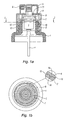
figures 1 sont des représentations d'un flacon de distribution selon un premier mode de réalisation de l'invention, respectivement en coupe longitudinale partielle (figure 1a ) et en coupe transversale selon la ligne I-I (figure 1b ) ; - les
figures 2 sont des représentations d'un flacon de distribution selon un deuxième mode de réalisation de l'invention, respectivement en coupe longitudinale partielle (figure 2a ) et en coupe transversale selon la ligne II-II (figure 2b ) ; - la
figure 3 est une représentation en perspective montrant le manchon et la frette d'un dispositif de fixation selon une réalisation de l'invention ; - la
figure 4 est une représentation en perspective montrant le manchon et la frette d'un dispositif de fixation selon une réalisation de l'invention ; - la
figure 5 est une représentation en perspective d'un manchon selon une variante de la réalisation de lafigure 4 .
- the
figures 1 are representations of a dispensing bottle according to a first embodiment of the invention, respectively in partial longitudinal section (figure 1a ) and in cross-section along line II (figure 1b ); - the
figures 2 are representations of a dispensing bottle according to a second embodiment of the invention, respectively in partial longitudinal section (figure 2a ) and in cross-section along line II-II (figure 2b ); - the
figure 3 is a perspective representation showing the sleeve and the hoop of a fastening device according to an embodiment of the invention; - the
figure 4 is a perspective representation showing the sleeve and the hoop of a fastening device according to an embodiment of the invention; - the
figure 5 is a perspective representation of a sleeve according to a variant of the embodiment of thefigure 4 .
En relation avec les figures, on décrit ci-dessous un flacon destiné à contenir un produit fluide en vue de sa distribution. Dans des exemples particuliers, le produit peut être un liquide ou une crème, par exemple un parfum, un produit cosmétique ou un produit pharmaceutique.In connection with the figures, there is described below a bottle for containing a fluid for distribution. In particular examples, the product may be a liquid or a cream, for example a perfume, a cosmetic product or a pharmaceutical product.
Le flacon peut être formé en matériau rigide, notamment en verre ou en matériau plastique, pour comprendre un corps 1 définissant un réservoir de conditionnement du produit. Le corps 1 est surmonté par un col 2 formé d'une seule pièce avec ledit corps en définissant une ouverture supérieure pour ledit réservoir.The bottle may be formed of rigid material, in particular glass or plastic material, to include a
Le flacon de distribution comprend également une pompe 3 montée dans l'ouverture supérieure en disposant les moyens d'alimentation de ladite pompe à l'intérieur du réservoir. La pompe représentée comprend un corps dont la périphérie est montée sans serrage dans l'ouverture.The dispensing bottle also comprises a
Le corps présente une partie inférieure qui est pourvue d'un orifice d'alimentation, les moyens d'alimentation comprenant un tube plongeur 4 présentant une partie supérieure fixée dans l'orifice et une partie inférieure disposée contre le fond du réservoir.The body has a lower portion which is provided with a feed orifice, the feed means comprising a
Par ailleurs, la pompe comprend un bouton poussoir 5 équipé d'un orifice de distribution 6. Selon une réalisation connue, le bouton 5 actionne en translation réversible un gicleur sur une course de distribution et un piston est également monté sur le gicleur entre un état d'obturation et un état d'alimentation des orifices dudit gicleur. Toutefois, l'invention n'est pas limitée à un mode de réalisation particulier de la pompe 3.Furthermore, the pump comprises a
Pour assurer le positionnement et la fixation de la pompe 3 par rapport au corps 1, le flacon comprend en outre un dispositif de fixation de ladite pompe sur le col dudit flacon, ledit dispositif comprenant un manchon 7 qui peut être réalisé de façon monobloc en matériau ductile, notamment en matière plastique de type polyoléfine.To ensure the positioning and fixing of the
Le dispositif de fixation comprend également une frette 8 d'habillage du manchon 7, notamment agencée pour masquer la partie de col du flacon, ladite frette pouvant être réalisée en matériau rigide tel qu'en métal, par exemple en aluminium, pour présenter une esthétique avantageuse. Dans les modes de réalisation représentés, la frette 8 présente une géométrie cylindrique de révolution qui s'étend axialement sur une longueur suffisante pour assurer sa fonction de masquage.The fixing device also comprises a
Le manchon 7 présente des moyens de solidarisation de la pompe et des moyens de fixation sur le col 2. Dans les modes de réalisation représentés, le manchon 7 présente une géométrie de révolution formée par une couronne supérieure 9 sous laquelle s'étend une jupe inférieure 10, le diamètre extérieur de la couronne 9 étant inférieur à celui de la jupe 10.The
La couronne 9 forme un logement 11 dans lequel le corps de la pompe 3 est solidarisé au manchon 7 par encliquetage, la fixation de l'ensemble manchon 7 - pompe 3 sur le flacon étant réalisée par vissage. Pour ce faire, l'extérieur du col 2 et l'intérieur de la jupe 10 sont pourvus d'un filet de vis 12 complémentaire. Toutefois, l'invention n'est pas limitée à une telle réalisation pour la fixation du manchon 7 sur le col 2. En particulier, une fixation par encliquetage du manchon 7 sur le col 2 peut être utilisée. De même, l'invention n'est pas limitée à une telle réalisation pour la solidarisation du corps de la pompe 3 dans le manchon 7.The
Pour assurer sa fonction d'habillage, la frette 8 est destinée à être montée par coulissement axial autour d'une portée périphérique 13 du manchon 7. Sur les figures, la portée périphérique 13 est annulaire et s'étend sur la périphérie extérieure de la jupe 10. En particulier, la portée périphérique 13 s'étend donc autour du filet de vis 12 qui est formé sur l'intérieur de la jupe 10.To ensure its cladding function, the
La portée périphérique 13 présente des cannelures axiales 14 qui sont séparées par des ponts de matière 15. En particulier, les cannelures 14 comprennent un fond en creux qui est délimité sur la portée 13 entre deux bords saillants, les ponts de matière 15 étant délimités par un bord de respectivement deux cannelures 14 adjacentes. Ainsi, les ponts de matière 15 forment un diamètre inscrit qui est supérieur à celui formé par le fond des cannelures 14.The
Dans les modes de réalisation représentés, les cannelures 14 s'étendent axialement sur tout l'extérieur de la jupe 10 de sorte à déboucher en partie supérieure et en partie inférieure de celle-ci.In the embodiments shown, the
Par ailleurs, la paroi interne de la frette 8 présente des nervures axiales 16 qui sont agencées pour être disposées dans les cannelures 14 lors du montage de ladite frette autour de la portée 13. Ainsi, les cannelures 14 étant préformées sur la portée 13, le montage ne nécessite pas une incrustation des nervures 16 mais un simple coulissement. Ainsi, notamment dans le cas où la portée 13 s'étend autour des moyens de fixation, on évite une possible déformation de ceux-ci lors du montage.Furthermore, the inner wall of the
En outre, l'engagement des nervures 16 dans les cannelures 14 assure la tenue en rotation de la frette 8 relativement au manchon 7, notamment lors du dévissage de la pompe 3. En particulier, pour combiner le coulissement sans déformation et la tenue en rotation, le diamètre inscrit formé par les nervures 16 peut être sensiblement identique à celui formé par les fonds des cannelures 14, ou très légèrement inférieur pour assurer par frottement une retenue axiale de la frette 8 sur le manchon 7.In addition, the engagement of the
La frette 8 peut être agencée pour être montée avec serrage axial sur le manchon 7, de sorte à fiabiliser la fixation de la frette 8 sur le manchon 7 relativement aux efforts axiaux. En particulier, la paroi interne de la frette 8 peut être agencée, notamment relativement à son diamètre nominal interne, pour assurer le serrage axial par interaction avec les ponts de matière 15.The
Par ailleurs, dans le cas d'un manchon 7 encliqueté sur le col 2, le serrage axial de la frette 8 peut assurer une fiabilisation dudit encliquetage en retenant radialement les moyens d'encliquetage.Furthermore, in the case of a
Selon une autre réalisation, la fixation de la pompe 3 peut être réalisée au moyen d'un manchon 7 comprenant une jupe déformable entre une configuration de montage dans laquelle ladite jupe est positionnable autour du col 2 et une configuration de serrage de ladite jupe autour dudit col pour assurer la fixation. En particulier, la configuration de serrage peut être obtenue par le montage de la frette 8 sur le manchon 7.According to another embodiment, the fixing of the
Par ailleurs, la frette 8 ou/ou le manchon 7 peut comprendre des moyens de fixation axiale de ladite frette autour dudit manchon. Sur les
Plus précisément, le jonc 17 est formé sur une deuxième jupe 19 du manchon 7 qui entoure la portée périphérique 13. La frette 8 comprend également deux jupes, une jupe intérieure 8a portant les nervures 16 et une jupe extérieure 8b portant la rainure 18.More specifically, the
En relation avec les
Par ailleurs, les
Sur les
Claims (11)
Applications Claiming Priority (1)
| Application Number | Priority Date | Filing Date | Title |
|---|---|---|---|
| FR0807377A FR2940251A1 (en) | 2008-12-22 | 2008-12-22 | DEVICE FOR FIXING A DISTRIBUTION PUMP TO A VIAL CONTAINING A PRODUCT |
Publications (2)
| Publication Number | Publication Date |
|---|---|
| EP2198973A1 true EP2198973A1 (en) | 2010-06-23 |
| EP2198973B1 EP2198973B1 (en) | 2012-02-22 |
Family
ID=40811173
Family Applications (1)
| Application Number | Title | Priority Date | Filing Date |
|---|---|---|---|
| EP09290977A Active EP2198973B1 (en) | 2008-12-22 | 2009-12-18 | Fixation device for a dispensing pump on a flask containing a product |
Country Status (5)
| Country | Link |
|---|---|
| US (1) | US8408422B2 (en) |
| EP (1) | EP2198973B1 (en) |
| AT (1) | ATE546230T1 (en) |
| ES (1) | ES2382421T3 (en) |
| FR (1) | FR2940251A1 (en) |
Cited By (2)
| Publication number | Priority date | Publication date | Assignee | Title |
|---|---|---|---|---|
| FR3001954A1 (en) * | 2013-02-14 | 2014-08-15 | Transformation Des Elastomeres A Usages Medicaux Et Ind Soc D | FIXING DEVICE FOR SEPARATING A FLUID PRODUCT TANK. |
| FR3067013A1 (en) * | 2017-06-06 | 2018-12-07 | Albea Services | ASSEMBLY OF A DISPENSING DEVICE FOR BOTTLE |
Families Citing this family (6)
| Publication number | Priority date | Publication date | Assignee | Title |
|---|---|---|---|---|
| WO2011116201A2 (en) * | 2010-03-18 | 2011-09-22 | Meadwestvaco Calmar, Inc. | Pump and bottle fitments and methods for using the same |
| FR2957903B1 (en) * | 2010-03-25 | 2014-01-24 | Valois Sas | FLUID PRODUCT DISPENSER. |
| US9475634B2 (en) * | 2010-12-01 | 2016-10-25 | Nicholas Joseph Prischak | Spray dispensing cup |
| US20140239018A1 (en) * | 2012-11-06 | 2014-08-28 | Dispensing Technologies B.V. | Spray/foam dispensers with improved venting ("optimus") |
| US20170073127A1 (en) * | 2015-09-11 | 2017-03-16 | Shanp-Yih Precision Industrial Co., Ltd. | Nozzle |
| GB202214557D0 (en) * | 2022-10-04 | 2022-11-16 | Berry Beaute Marolles Sas | Collar for screw pump |
Citations (4)
| Publication number | Priority date | Publication date | Assignee | Title |
|---|---|---|---|---|
| US4366921A (en) * | 1981-09-28 | 1983-01-04 | Ethyl Products Company | Child-resistant closure device |
| EP0638367A1 (en) * | 1993-08-10 | 1995-02-15 | L'oreal | Dispensing device for liquid or pasty products |
| FR2884806A1 (en) * | 2005-04-25 | 2006-10-27 | Valois Sas | Distribution unit e.g. pump fixing device for e.g. perfumery field, has shoulder forming gripping unit, and stop unit formed by lower end, where units define axial retention unit for locking hoop on ring in separated axial positions |
| FR2891530A1 (en) * | 2005-10-04 | 2007-04-06 | Valois Sas | Covering component with a network of projections mounted on a fixing ring to form a fixing device for attaching a distribution system to the neck of a container to provide technical and/or aesthetic functions |
Family Cites Families (4)
| Publication number | Priority date | Publication date | Assignee | Title |
|---|---|---|---|---|
| US4346821A (en) * | 1978-03-16 | 1982-08-31 | Afa Consolidated Corporation | Child-resistant closures for container mounted spray dispensers |
| US6695171B2 (en) * | 2002-02-12 | 2004-02-24 | Seaquistperfect Dispensing Foreign, Inc. | Pump dispenser |
| FR2931138B1 (en) * | 2008-05-19 | 2010-05-28 | Valois Sas | FLUID PRODUCT DISPENSER |
| FR2939776B1 (en) * | 2008-12-12 | 2013-07-05 | Valois Sas | FIXING RING AND DISTRIBUTOR COMPRISING SUCH A RING. |
-
2008
- 2008-12-22 FR FR0807377A patent/FR2940251A1/en not_active Withdrawn
-
2009
- 2009-12-18 AT AT09290977T patent/ATE546230T1/en active
- 2009-12-18 EP EP09290977A patent/EP2198973B1/en active Active
- 2009-12-18 ES ES09290977T patent/ES2382421T3/en active Active
-
2010
- 2010-02-03 US US12/699,707 patent/US8408422B2/en active Active
Patent Citations (5)
| Publication number | Priority date | Publication date | Assignee | Title |
|---|---|---|---|---|
| US4366921A (en) * | 1981-09-28 | 1983-01-04 | Ethyl Products Company | Child-resistant closure device |
| EP0638367A1 (en) * | 1993-08-10 | 1995-02-15 | L'oreal | Dispensing device for liquid or pasty products |
| FR2884806A1 (en) * | 2005-04-25 | 2006-10-27 | Valois Sas | Distribution unit e.g. pump fixing device for e.g. perfumery field, has shoulder forming gripping unit, and stop unit formed by lower end, where units define axial retention unit for locking hoop on ring in separated axial positions |
| FR2891530A1 (en) * | 2005-10-04 | 2007-04-06 | Valois Sas | Covering component with a network of projections mounted on a fixing ring to form a fixing device for attaching a distribution system to the neck of a container to provide technical and/or aesthetic functions |
| WO2007042701A1 (en) | 2005-10-04 | 2007-04-19 | Valois Sas | Cover member, method of producing one such member and a fluid product dispenser using one such member |
Cited By (4)
| Publication number | Priority date | Publication date | Assignee | Title |
|---|---|---|---|---|
| FR3001954A1 (en) * | 2013-02-14 | 2014-08-15 | Transformation Des Elastomeres A Usages Medicaux Et Ind Soc D | FIXING DEVICE FOR SEPARATING A FLUID PRODUCT TANK. |
| WO2014125202A1 (en) * | 2013-02-14 | 2014-08-21 | Aptar Stelmi Sas | Fastening device for sealing a fluid product reservoir |
| US9776775B2 (en) | 2013-02-14 | 2017-10-03 | Aptar Stelmi Sas | Fastening device for sealing a fluid product reservoir |
| FR3067013A1 (en) * | 2017-06-06 | 2018-12-07 | Albea Services | ASSEMBLY OF A DISPENSING DEVICE FOR BOTTLE |
Also Published As
| Publication number | Publication date |
|---|---|
| US20110031281A1 (en) | 2011-02-10 |
| US8408422B2 (en) | 2013-04-02 |
| EP2198973B1 (en) | 2012-02-22 |
| ATE546230T1 (en) | 2012-03-15 |
| FR2940251A1 (en) | 2010-06-25 |
| ES2382421T3 (en) | 2012-06-08 |
Similar Documents
| Publication | Publication Date | Title |
|---|---|---|
| EP2198973B1 (en) | Fixation device for a dispensing pump on a flask containing a product | |
| EP2689858B1 (en) | Sleeve for sealingly attaching a dispensing member onto the neck of a bottle containing a fluid product to be dispensed | |
| EP2279799B1 (en) | System for fixing a distribution pump to the neck of a bottle containing a fluid product | |
| EP1924362B1 (en) | Intercalated locking ring | |
| EP2641660B1 (en) | Method of fastening a dispenser to a reservoir | |
| EP3034176B1 (en) | System for actuating a member for dispensing a fluid product | |
| FR2908116A1 (en) | FLUID PRODUCT DISPENSER | |
| WO2000023199A1 (en) | Low capacity pump with enhanced compatibility | |
| EP2397422B1 (en) | Fluid dispensing system | |
| EP3603817A1 (en) | Easy mounting and removal of a pump relative to the container | |
| EP2135682B2 (en) | Dispenser for a liquid product comprising a deformable fixing ring for retaining the dispensing pump which can be unscrewed | |
| EP1701800A1 (en) | Fluid product dispensing member and dispenser comprising one such member | |
| EP0583193B1 (en) | Improvement to the assembly of a pump in a container | |
| EP1952893B1 (en) | Bottle comprising a neck assembled on a body | |
| FR2845357A1 (en) | Dispenser fixing element for neck of container comprising zone coated with layer of adhesive making contact with rim of container neck | |
| EP2308604B1 (en) | Dispensing system for a fluid product | |
| EP3256261B1 (en) | Mounting arragnement for a dispenser | |
| FR2894566A1 (en) | Packaging for dispensing fluids and pastes, e.g. cosmetics, comprises a container plus a distribution-closure system with a shaft screwed into the container outlet and a valve actuated by the removable container cap | |
| EP3829387B1 (en) | Device for packaging and applying a cosmetic product | |
| FR2848194A1 (en) | Pump/valve fixation device for cosmetic field, has reinforcement band mounted by axial engagement on fixation ring to mask partially band consisting of hooking mechanism comprising blockage and rotation units | |
| EP3034177B1 (en) | System for storing a fluid product, comprising a bottle in an outer covering | |
| FR2932783A1 (en) | FLUID DISPENSING BOTTLE COMPRISING A DEFORMABLE AND DEVILABLE SLEEVE | |
| FR2957900A1 (en) | Fixing system for dispensing bottle to fix dispensing unit on neck of bottle utilized for dispensing e.g. perfume in cosmetic application by e.g. perfumers, has stop units for preventing sliding of ferrule beyond its raised position | |
| FR2831142A1 (en) | Spray can is mounted in rigid shell and is held in place by plate with central aperture which fits around neck of can, between it and shell | |
| FR2954293A1 (en) | Element e.g. pump, for distributing fluid product e.g. e.g. cosmetic product, has axial guiding units placed between body and actuation rod to prevent movement of actuation rod in rotation with respect to body |
Legal Events
| Date | Code | Title | Description |
|---|---|---|---|
| PUAI | Public reference made under article 153(3) epc to a published international application that has entered the european phase |
Free format text: ORIGINAL CODE: 0009012 |
|
| AK | Designated contracting states |
Kind code of ref document: A1 Designated state(s): AT BE BG CH CY CZ DE DK EE ES FI FR GB GR HR HU IE IS IT LI LT LU LV MC MK MT NL NO PL PT RO SE SI SK SM TR |
|
| AX | Request for extension of the european patent |
Extension state: AL BA RS |
|
| 17P | Request for examination filed |
Effective date: 20101222 |
|
| GRAP | Despatch of communication of intention to grant a patent |
Free format text: ORIGINAL CODE: EPIDOSNIGR1 |
|
| RIC1 | Information provided on ipc code assigned before grant |
Ipc: B65D 41/00 20060101ALN20110831BHEP Ipc: B05B 11/00 20060101AFI20110831BHEP Ipc: A45D 34/00 20060101ALN20110831BHEP |
|
| GRAS | Grant fee paid |
Free format text: ORIGINAL CODE: EPIDOSNIGR3 |
|
| GRAA | (expected) grant |
Free format text: ORIGINAL CODE: 0009210 |
|
| AK | Designated contracting states |
Kind code of ref document: B1 Designated state(s): AT BE BG CH CY CZ DE DK EE ES FI FR GB GR HR HU IE IS IT LI LT LU LV MC MK MT NL NO PL PT RO SE SI SK SM TR |
|
| REG | Reference to a national code |
Ref country code: GB Ref legal event code: FG4D Free format text: NOT ENGLISH |
|
| REG | Reference to a national code |
Ref country code: CH Ref legal event code: EP |
|
| REG | Reference to a national code |
Ref country code: AT Ref legal event code: REF Ref document number: 546230 Country of ref document: AT Kind code of ref document: T Effective date: 20120315 |
|
| REG | Reference to a national code |
Ref country code: IE Ref legal event code: FG4D Free format text: LANGUAGE OF EP DOCUMENT: FRENCH |
|
| REG | Reference to a national code |
Ref country code: DE Ref legal event code: R096 Ref document number: 602009005465 Country of ref document: DE Effective date: 20120419 |
|
| REG | Reference to a national code |
Ref country code: ES Ref legal event code: FG2A Ref document number: 2382421 Country of ref document: ES Kind code of ref document: T3 Effective date: 20120608 |
|
| REG | Reference to a national code |
Ref country code: NL Ref legal event code: VDEP Effective date: 20120222 |
|
| LTIE | Lt: invalidation of european patent or patent extension |
Effective date: 20120222 |
|
| PG25 | Lapsed in a contracting state [announced via postgrant information from national office to epo] |
Ref country code: LT Free format text: LAPSE BECAUSE OF FAILURE TO SUBMIT A TRANSLATION OF THE DESCRIPTION OR TO PAY THE FEE WITHIN THE PRESCRIBED TIME-LIMIT Effective date: 20120222 Ref country code: NL Free format text: LAPSE BECAUSE OF FAILURE TO SUBMIT A TRANSLATION OF THE DESCRIPTION OR TO PAY THE FEE WITHIN THE PRESCRIBED TIME-LIMIT Effective date: 20120222 Ref country code: NO Free format text: LAPSE BECAUSE OF FAILURE TO SUBMIT A TRANSLATION OF THE DESCRIPTION OR TO PAY THE FEE WITHIN THE PRESCRIBED TIME-LIMIT Effective date: 20120522 Ref country code: HR Free format text: LAPSE BECAUSE OF FAILURE TO SUBMIT A TRANSLATION OF THE DESCRIPTION OR TO PAY THE FEE WITHIN THE PRESCRIBED TIME-LIMIT Effective date: 20120222 Ref country code: IS Free format text: LAPSE BECAUSE OF FAILURE TO SUBMIT A TRANSLATION OF THE DESCRIPTION OR TO PAY THE FEE WITHIN THE PRESCRIBED TIME-LIMIT Effective date: 20120622 |
|
| PG25 | Lapsed in a contracting state [announced via postgrant information from national office to epo] |
Ref country code: FI Free format text: LAPSE BECAUSE OF FAILURE TO SUBMIT A TRANSLATION OF THE DESCRIPTION OR TO PAY THE FEE WITHIN THE PRESCRIBED TIME-LIMIT Effective date: 20120222 Ref country code: PT Free format text: LAPSE BECAUSE OF FAILURE TO SUBMIT A TRANSLATION OF THE DESCRIPTION OR TO PAY THE FEE WITHIN THE PRESCRIBED TIME-LIMIT Effective date: 20120622 Ref country code: GR Free format text: LAPSE BECAUSE OF FAILURE TO SUBMIT A TRANSLATION OF THE DESCRIPTION OR TO PAY THE FEE WITHIN THE PRESCRIBED TIME-LIMIT Effective date: 20120523 Ref country code: LV Free format text: LAPSE BECAUSE OF FAILURE TO SUBMIT A TRANSLATION OF THE DESCRIPTION OR TO PAY THE FEE WITHIN THE PRESCRIBED TIME-LIMIT Effective date: 20120222 |
|
| REG | Reference to a national code |
Ref country code: IE Ref legal event code: FD4D |
|
| REG | Reference to a national code |
Ref country code: AT Ref legal event code: MK05 Ref document number: 546230 Country of ref document: AT Kind code of ref document: T Effective date: 20120222 |
|
| PG25 | Lapsed in a contracting state [announced via postgrant information from national office to epo] |
Ref country code: CY Free format text: LAPSE BECAUSE OF FAILURE TO SUBMIT A TRANSLATION OF THE DESCRIPTION OR TO PAY THE FEE WITHIN THE PRESCRIBED TIME-LIMIT Effective date: 20120222 |
|
| PG25 | Lapsed in a contracting state [announced via postgrant information from national office to epo] |
Ref country code: DK Free format text: LAPSE BECAUSE OF FAILURE TO SUBMIT A TRANSLATION OF THE DESCRIPTION OR TO PAY THE FEE WITHIN THE PRESCRIBED TIME-LIMIT Effective date: 20120222 Ref country code: CZ Free format text: LAPSE BECAUSE OF FAILURE TO SUBMIT A TRANSLATION OF THE DESCRIPTION OR TO PAY THE FEE WITHIN THE PRESCRIBED TIME-LIMIT Effective date: 20120222 Ref country code: RO Free format text: LAPSE BECAUSE OF FAILURE TO SUBMIT A TRANSLATION OF THE DESCRIPTION OR TO PAY THE FEE WITHIN THE PRESCRIBED TIME-LIMIT Effective date: 20120222 Ref country code: EE Free format text: LAPSE BECAUSE OF FAILURE TO SUBMIT A TRANSLATION OF THE DESCRIPTION OR TO PAY THE FEE WITHIN THE PRESCRIBED TIME-LIMIT Effective date: 20120222 Ref country code: IE Free format text: LAPSE BECAUSE OF FAILURE TO SUBMIT A TRANSLATION OF THE DESCRIPTION OR TO PAY THE FEE WITHIN THE PRESCRIBED TIME-LIMIT Effective date: 20120222 Ref country code: SI Free format text: LAPSE BECAUSE OF FAILURE TO SUBMIT A TRANSLATION OF THE DESCRIPTION OR TO PAY THE FEE WITHIN THE PRESCRIBED TIME-LIMIT Effective date: 20120222 Ref country code: SE Free format text: LAPSE BECAUSE OF FAILURE TO SUBMIT A TRANSLATION OF THE DESCRIPTION OR TO PAY THE FEE WITHIN THE PRESCRIBED TIME-LIMIT Effective date: 20120222 Ref country code: PL Free format text: LAPSE BECAUSE OF FAILURE TO SUBMIT A TRANSLATION OF THE DESCRIPTION OR TO PAY THE FEE WITHIN THE PRESCRIBED TIME-LIMIT Effective date: 20120222 |
|
| PG25 | Lapsed in a contracting state [announced via postgrant information from national office to epo] |
Ref country code: SK Free format text: LAPSE BECAUSE OF FAILURE TO SUBMIT A TRANSLATION OF THE DESCRIPTION OR TO PAY THE FEE WITHIN THE PRESCRIBED TIME-LIMIT Effective date: 20120222 |
|
| PLBE | No opposition filed within time limit |
Free format text: ORIGINAL CODE: 0009261 |
|
| STAA | Information on the status of an ep patent application or granted ep patent |
Free format text: STATUS: NO OPPOSITION FILED WITHIN TIME LIMIT |
|
| 26N | No opposition filed |
Effective date: 20121123 |
|
| PG25 | Lapsed in a contracting state [announced via postgrant information from national office to epo] |
Ref country code: AT Free format text: LAPSE BECAUSE OF FAILURE TO SUBMIT A TRANSLATION OF THE DESCRIPTION OR TO PAY THE FEE WITHIN THE PRESCRIBED TIME-LIMIT Effective date: 20120222 |
|
| REG | Reference to a national code |
Ref country code: DE Ref legal event code: R097 Ref document number: 602009005465 Country of ref document: DE Effective date: 20121123 |
|
| BERE | Be: lapsed |
Owner name: REXAM DISPENSING SYSTEMS Effective date: 20121231 |
|
| PG25 | Lapsed in a contracting state [announced via postgrant information from national office to epo] |
Ref country code: BG Free format text: LAPSE BECAUSE OF FAILURE TO SUBMIT A TRANSLATION OF THE DESCRIPTION OR TO PAY THE FEE WITHIN THE PRESCRIBED TIME-LIMIT Effective date: 20120522 Ref country code: MC Free format text: LAPSE BECAUSE OF NON-PAYMENT OF DUE FEES Effective date: 20121231 |
|
| PG25 | Lapsed in a contracting state [announced via postgrant information from national office to epo] |
Ref country code: BE Free format text: LAPSE BECAUSE OF NON-PAYMENT OF DUE FEES Effective date: 20121231 |
|
| PG25 | Lapsed in a contracting state [announced via postgrant information from national office to epo] |
Ref country code: MT Free format text: LAPSE BECAUSE OF FAILURE TO SUBMIT A TRANSLATION OF THE DESCRIPTION OR TO PAY THE FEE WITHIN THE PRESCRIBED TIME-LIMIT Effective date: 20120222 |
|
| PG25 | Lapsed in a contracting state [announced via postgrant information from national office to epo] |
Ref country code: TR Free format text: LAPSE BECAUSE OF FAILURE TO SUBMIT A TRANSLATION OF THE DESCRIPTION OR TO PAY THE FEE WITHIN THE PRESCRIBED TIME-LIMIT Effective date: 20120222 |
|
| PG25 | Lapsed in a contracting state [announced via postgrant information from national office to epo] |
Ref country code: LU Free format text: LAPSE BECAUSE OF NON-PAYMENT OF DUE FEES Effective date: 20121218 Ref country code: SM Free format text: LAPSE BECAUSE OF FAILURE TO SUBMIT A TRANSLATION OF THE DESCRIPTION OR TO PAY THE FEE WITHIN THE PRESCRIBED TIME-LIMIT Effective date: 20120222 |
|
| REG | Reference to a national code |
Ref country code: ES Ref legal event code: PC2A Owner name: ALBEA LE TREPORT, SOCIETE PAR ACTIONS SIMPLIFIEE Effective date: 20140617 |
|
| REG | Reference to a national code |
Ref country code: DE Ref legal event code: R081 Ref document number: 602009005465 Country of ref document: DE Owner name: ALBEA LE TREPORT, FR Free format text: FORMER OWNER: REXAM DISPENSING SYSTEMS, LE TREPORT, FR Effective date: 20140519 |
|
| PG25 | Lapsed in a contracting state [announced via postgrant information from national office to epo] |
Ref country code: HU Free format text: LAPSE BECAUSE OF FAILURE TO SUBMIT A TRANSLATION OF THE DESCRIPTION OR TO PAY THE FEE WITHIN THE PRESCRIBED TIME-LIMIT Effective date: 20091218 |
|
| REG | Reference to a national code |
Ref country code: CH Ref legal event code: PL |
|
| GBPC | Gb: european patent ceased through non-payment of renewal fee |
Effective date: 20131218 |
|
| REG | Reference to a national code |
Ref country code: FR Ref legal event code: CD Owner name: ALBEA LE TREPORT, FR Effective date: 20140822 |
|
| PG25 | Lapsed in a contracting state [announced via postgrant information from national office to epo] |
Ref country code: CH Free format text: LAPSE BECAUSE OF NON-PAYMENT OF DUE FEES Effective date: 20131231 Ref country code: LI Free format text: LAPSE BECAUSE OF NON-PAYMENT OF DUE FEES Effective date: 20131231 |
|
| PG25 | Lapsed in a contracting state [announced via postgrant information from national office to epo] |
Ref country code: GB Free format text: LAPSE BECAUSE OF NON-PAYMENT OF DUE FEES Effective date: 20131218 |
|
| PG25 | Lapsed in a contracting state [announced via postgrant information from national office to epo] |
Ref country code: MK Free format text: LAPSE BECAUSE OF FAILURE TO SUBMIT A TRANSLATION OF THE DESCRIPTION OR TO PAY THE FEE WITHIN THE PRESCRIBED TIME-LIMIT Effective date: 20120222 |
|
| REG | Reference to a national code |
Ref country code: FR Ref legal event code: PLFP Year of fee payment: 7 |
|
| REG | Reference to a national code |
Ref country code: FR Ref legal event code: PLFP Year of fee payment: 8 |
|
| REG | Reference to a national code |
Ref country code: FR Ref legal event code: PLFP Year of fee payment: 9 |
|
| REG | Reference to a national code |
Ref country code: DE Ref legal event code: R082 Ref document number: 602009005465 Country of ref document: DE Representative=s name: ADARES PATENT- UND RECHTSANWAELTE REININGER & , DE |
|
| PGFP | Annual fee paid to national office [announced via postgrant information from national office to epo] |
Ref country code: ES Payment date: 20230102 Year of fee payment: 14 |
|
| PGFP | Annual fee paid to national office [announced via postgrant information from national office to epo] |
Ref country code: DE Payment date: 20221228 Year of fee payment: 14 |
|
| PGFP | Annual fee paid to national office [announced via postgrant information from national office to epo] |
Ref country code: IT Payment date: 20231220 Year of fee payment: 15 Ref country code: FR Payment date: 20231227 Year of fee payment: 15 |
|
| PGFP | Annual fee paid to national office [announced via postgrant information from national office to epo] |
Ref country code: ES Payment date: 20240102 Year of fee payment: 15 |