EP2198802A1 - Dispositif d'articulation d'un ensemble orthodontique apte à provoquer un déplacement d'une mandibule par rapport à un maxillaire - Google Patents
Dispositif d'articulation d'un ensemble orthodontique apte à provoquer un déplacement d'une mandibule par rapport à un maxillaire Download PDFInfo
- Publication number
- EP2198802A1 EP2198802A1 EP09306215A EP09306215A EP2198802A1 EP 2198802 A1 EP2198802 A1 EP 2198802A1 EP 09306215 A EP09306215 A EP 09306215A EP 09306215 A EP09306215 A EP 09306215A EP 2198802 A1 EP2198802 A1 EP 2198802A1
- Authority
- EP
- European Patent Office
- Prior art keywords
- tip
- armature
- fixed
- rod
- axis
- Prior art date
- Legal status (The legal status is an assumption and is not a legal conclusion. Google has not performed a legal analysis and makes no representation as to the accuracy of the status listed.)
- Granted
Links
Images


Classifications
-
- A—HUMAN NECESSITIES
- A61—MEDICAL OR VETERINARY SCIENCE; HYGIENE
- A61C—DENTISTRY; APPARATUS OR METHODS FOR ORAL OR DENTAL HYGIENE
- A61C7/00—Orthodontics, i.e. obtaining or maintaining the desired position of teeth, e.g. by straightening, evening, regulating, separating, or by correcting malocclusions
- A61C7/36—Devices acting between upper and lower teeth
Definitions
- the invention relates to the technical sector of mandibular advancement orthoses.
- the goal is to move the mandible forward with respect to its original position a very small distance of the order of a few millimeters, at first, in particular, to stimulate growth.
- This mandibular propulsion can be used to increase the respiratory flow, in order to solve the problems of sleep apnea syndromes.
- the invention more particularly relates to an orthodontic assembly of the type perfectly known to a person skilled in the art, under the name "Herbst orthosis” or "Herbst connecting rods”.
- this type of orthosis has gutters co-operating, respectively, with the row of upper teeth and the row of lower teeth.
- These gutters are generally made of a rigid material, for example thermoformed acrylic resin, and are connected to one another by a system of rods mounted with sliding capacity. More particularly, two metal rods are arranged, respectively, on each side of an armature secured to a portion of the upper gutter and the lower gutter. The two links are connected with articulation capacity on the frame, substantially at the level of the first molars for the upper gutter and substantially at the level of the canine for the lower gutter.
- the articulation of the rods, at the corresponding parts of the armature, as indicated above, is effected at means of an axis disposed in a substantially horizontal plane, so that the hinge movement of the rods is limited in a vertical plane.
- This limited displacement of the mandible relative to the maxillary, in a postero-anterior direction, is not satisfactory. It has been important that the patient, equipped with this type of orthodontic assembly, can also have great freedom of lateral movement of the mandible relative to the maxillary. It has also been found that this type of articulation, horizontal axis, is bulky and makes delicate the cooperation of the links of the upper and lower gutters.
- the object of the invention is to remedy these disadvantages in a simple, safe, effective and rational manner.
- the problem to be solved by the invention is to confer total freedom of articulation of the rods both in an anteroposterior plane as in a lateral plane, and this in a small footprint.
- the tip has a recess to be fixed coaxially to the rod.
- the tip is fixed in superposition of one of the ends of the rod.
- the support element is offset laterally relative to the corresponding armature portion.
- the support member has a coupling sleeve with the corresponding armature portion, said sleeve having a remote socket in which is fixed the axis of the ball joint.
- FIG. 1 an orthodontic assembly for moving the mandible relative to the maxillary.
- this assembly may be constituted by an upper gutter (GS) cooperating with a part of the toothing of the maxilla and a lower gutter (GI) cooperating with all or part of the teeth of the mandible.
- each gutter (GS) and (GI) is made by thermoforming or in resin with the technique "salt and pepper" by adding a track on the mandibular occlusal part and on the maxillary occlusal part.
- each of the gutters (GS) and (GI) has reinforcements (1) and (2) for the coupling, with articulation capacity, of a system of rods (3) and (4) mounted with capacity linear sliding guide in translation. This assembly is carried out in a symmetrical manner on either side of the longitudinal axis of each of the gutters.
- each of the rods (3) is articulated on a part of the armature (1) of the lower gutter relative to the mandible, while each of the rods (4) is hinged to a portion of the armature (2) relating to the upper gutter of the maxillary.
- the hinge device comprises, for each link (3) and (4), coupling means of the ball type, able to allow, in a horizontal plane, a joint about 360 ° of the corresponding rod and, in a vertical plane, an articulation of at least about 90 ° of the corresponding link.
- the ball (5) is integral with an axis (5a) oriented substantially perpendicularly to a support member (6) integral with a portion of the corresponding armature (1) or (2).
- the support (6) is integral with the armature (1) or (2) by any known and appropriate means, for example, by clipping.
- the coupling means are constituted by a tip (7) having a hemispherical cage (7a) adapted to receive the ball (5).
- this hemispherical cage (7a) is in communication with an opening (7b) opening on one side of the mouthpiece and formed perpendicularly to its longitudinal axis and in a plane parallel to that receiving the axis (5a). ) of the sphere (5).
- the slot (7b) allows a vertical movement of the rod (3) or (4) of about 90 ° . It therefore appears that this articulation of the ball-type, with the sphere (5) in combination with the slot or opening (7b) of the tip (7), allows, in a horizontal plane, a displacement about 360 ° ( figure 5 ) and, in a vertical plane, a displacement of approximately 90 ° ( figure 4 ), while preventing a tilting effect of said tip. We thus obtain a perfect control of mandibular propulsion movements and laterality.
- the part of the support element (6) receiving the ball (5) is offset laterally relative to the corresponding reinforcing part (1) or (2).
- the support element (6) has a coupling sleeve (6a) fixed on the armatures (1) and (2), which sleeve (6a) has a sleeve (6b) where is fixed the axis (5a). ) of the ball (5).
- the zone of articulation of the rods (3) and (4), with respect to the corresponding parts of the armatures (1) and (2) is determined to correspond generally to the level of the first molars. for the gutter of the maxillary and at the level of the canines for the gutter of the mandible.
- the support element (6) is therefore positioned and fixed accordingly on the corresponding reinforcing parts (1) and (2).
- the axis (5a) of the ball (5) is fixed on the support member (6) with disassembly capacity.
- the axis (5a) of the ball is threaded to be screwed into a threaded hole (6b1) of the support (6).
- the coupling of each of the rods (3) and (4) with the sleeve (7) on the support member (6), in combination with the ball (5), is particularly simple and fast.
- the coupling end (7) is arranged coaxially with the link (3).
- the tip (7) has a recess (7c) in which is fixed by any known and appropriate means, the end of the rod (3).
- This solution is, for example, used for connected rods with articulation capacity on the side of the mandible.
- the coupling end (7) is fixed in superposition of the end of the connecting rod (4).
- This embodiment is, for example, used for connected rods with articulation capacity on the jaw side.
- the rod (3) for example, is mounted with linear sliding capacity guided inside the link (4).
- the rod (3) is constituted by a solid cylindrical body, while the rod (4) is constituted by a tube.
- the figure 6 shows the coupling of the two links before mounting on their respective support elements (6), under the conditions indicated above.
- the ball (5) has a recess (5b) adapted to cooperate with a drive member of the screwdriver type, for example.
- the tube forming the rod (4) abuts against the tip (7) of the cylindrical body or rod constituting the rod (3). Rings can be added on the cylindrical rod to adjust the gauge.
Landscapes
- Health & Medical Sciences (AREA)
- Oral & Maxillofacial Surgery (AREA)
- Dentistry (AREA)
- Epidemiology (AREA)
- Life Sciences & Earth Sciences (AREA)
- Animal Behavior & Ethology (AREA)
- General Health & Medical Sciences (AREA)
- Public Health (AREA)
- Veterinary Medicine (AREA)
- Orthopedics, Nursing, And Contraception (AREA)
- Dental Tools And Instruments Or Auxiliary Dental Instruments (AREA)
Abstract
Description
- L'invention se rattache au secteur technique des orthèses d'avancement mandibulaire.
- Différentes solutions ont été proposées pour provoquer un déplacement de la mandibule par rapport au maxillaire.
- Le but recherché est de déplacer en avant la mandibule par rapport à sa position d'origine d'une très faible distance de l'ordre de quelques millimètres, dans un premier temps, afin, notamment, de stimuler la croissance. Cette propulsion mandibulaire peut être utilisée pour augmenter le flux respiratoire, afin de régler les problèmes de syndromes d'apnée du sommeil.
- L'invention concerne plus particulièrement un ensemble orthodontique du type parfaitement connu pour un homme du métier, sous le nom de « orthèse de Herbst » ou « bielles de Herbst ».
- Pour l'essentiel, ce type d'orthèse présente des gouttières coopérant, respectivement, avec la rangée de dents du haut et la rangée de dents du bas. Ces gouttières sont généralement réalisées dans un matériau rigide, par exemple en résine acrylique thermoformée, et sont reliées l'une à l'autre par un système de biellettes montées avec capacité de coulissement. Plus particulièrement, deux biellettes métalliques sont disposées, respectivement, de chaque côté d'une armature rendue solidaire d'une partie de la gouttière supérieure et de la gouttière inférieure. Les deux biellettes sont reliées avec capacité d'articulation sur l'armature, sensiblement au niveau des premières molaires pour la gouttière supérieure et sensiblement au niveau de la canine pour la gouttière inférieure. L'articulation des biellettes, au niveau des parties correspondantes de l'armature, comme indiqué précédemment, s'effectue au moyen d'un axe disposé dans un plan sensiblement horizontal, de sorte que le mouvement d'articulation des biellettes est limité dans un plan vertical.
Ce déplacement limité de la mandibule par rapport au maxillaire, dans une direction postéro-antérieure, n'est pas satisfaisant. Il s'est avéré important que le patient, équipé de ce type d'ensemble orthodontique, puisse également avoir une grande liberté de déplacement latéral de la mandibule par rapport au maxillaire. On a pu également constater que ce type d'articulation, à axe horizontal, est encombrant et rend délicate la coopération des biellettes des gouttières supérieure et inférieure. - On connaît également des systèmes d'articulation d'un ensemble orthopédique dans lequel les biellettes sont accouplées avec les gouttières supérieure et inférieure, au moyen d'une rotule. On peut citer, par exemple, l'enseignement du brevet
US 5,620,321 . Toutefois, la solution décrite dans ce brevet n'est pas totalement satisfaisante étant donné qu'il n'est pas possible d'obtenir des mouvements de latéralité. - L'invention s'est fixée pour but de remédier à ces inconvénients d'une manière simple, sûre, efficace et rationnelle.
- Le problème que se propose de résoudre l'invention est de conférer une totale liberté d'articulation des biellettes tant dans un plan antéro-postérieur que dans un plan latéral, et ceci dans un encombrement réduit.
- Pour résoudre un tel problème, il a été conçu et mis au point un dispositif d'articulation d'un ensemble orthodontique apte à provoquer un déplacement d'une mandibule par rapport à un maxillaire du type de ceux connus et définis dans la première partie de la revendication 1.
- Selon l'invention, le problème posé est résolu par les caractéristiques relevant de la deuxième partie de la revendication 1.
- Il résulte de ces caractéristiques une parfaite maîtrise des mouvements de propulsion mandibulaire (mouvement antéro-postérieur) et de latéralité, évitant tout phénomène de basculement de l'embout d'accouplement et, par conséquent, des biellettes.
- Dans une forme de réalisation et du côté de la mandibule, l'embout présente un chambrage pour être fixé coaxialement à la biellette.
- Dans une forme de réalisation et du côté du maxillaire, l'embout est fixé en superposition de l'une des extrémités de la biellette.
- Pour résoudre le problème posé d'améliorer l'articulation des biellettes, tout en respectant un faible encombrement, l'élément support est déporté latéralement par rapport à la partie d'armature correspondante. L'élément support présente un manchon d'accouplement avec la partie d'armature correspondante, ledit manchon présentant une douille déportée dans laquelle est fixé l'axe de la rotule.
- L'invention est exposée ci-après plus en détail à l'aide des figures des dessins annexés dans lesquels :
- la
figure 1 est une vue en perspective à caractère schématique montrant un ensemble orthodontique dont les gouttières supérieure et inférieure sont reliées par un système de biellettes montées avec capacité d'articulation, selon les caractéristiques du dispositif de l'invention ; - la
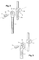
figure 2 est une vue en perspective avant montage de l'extrémité de l'une des biellettes sur l'élément support considéré du côté de la mandibule ; - la
figure 3 est une vue en perspective avant montage de l'extrémité de la biellette sur l'élément support considéré du côté du maxillaire ; - la
figure 4 est une vue partielle en coupe longitudinale montrant le principe de l'articulation des biellettes par rapport à un élément support dans un plan antéro-postérieur d'environ 90° ; - la
figure 5 est une vue en plan correspondant à lafigure 4 montrant le principe d'articulation dans un plan latéral (360°) ; - la
figure 6 est une vue en perspective après accouplement des biellettes et avant montage sur l'élément support correspondant. - On a illustré
figure 1 , à titre d'exemple indicatif nullement limitatif, un ensemble orthodontique pour le déplacement de la mandibule par rapport au maxillaire. D'une manière parfaitement connue pour un homme du métier, cet ensemble peut être constitué par une gouttière supérieure (GS) coopérant avec une partie de la denture du maxillaire et d'une gouttière inférieure (GI) coopérant avec la totalité ou une partie de la denture de la mandibule.
Comme déjà indiqué, chaque gouttière (GS) et (GI) est réalisée par thermoformage ou bien en résine avec la technique « poivre et sel » en ajoutant une piste sur la partie occlusale mandibulaire et sur la partie occlusale maxillaire. En outre, chacune des gouttières (GS) et (GI) présente des armatures (1) et (2) pour l'accouplement, avec capacité d'articulation, d'un système de biellettes (3) et (4) montées avec capacité de coulissement linéaire guidé en translation. Ce montage est réalisé d'une manière symétrique de part et d'autre de l'axe longitudinal de chacune des gouttières. - Dans l'exemple illustré, chacune des biellettes (3) est articulée sur une partie de l'armature (1) de la gouttière inférieure relative à la mandibule, tandis que chacune des biellettes (4) est articulée sur une partie de l'armature (2) relatif à la gouttière supérieure du maxillaire.
- Selon une caractéristique à la base de l'invention, le dispositif d'articulation comprend, pour chaque biellette (3) et (4), des moyens d'accouplement du type à rotule, aptes à permettre, dans un plan horizontal, une articulation d'environ 360° de la biellette correspondante et, dans un plan vertical, une articulation d'environ 90° au moins de la biellette correspondante. D'une manière importante, la rotule (5) est solidaire d'un axe (5a) orienté sensiblement perpendiculairement à un élément support (6) solidaire d'une partie de l'armature correspondante (1) ou (2).
- Le support (6) est solidaire de l'armature (1) ou (2) par tout moyen connu et approprié, par exemple, par clipage.
- Pour chacune des biellettes (3) et (4), les moyens d'accouplement sont constitués par un embout (7) présentant une cage hémisphérique (7a) apte à recevoir la rotule (5). D'une manière importante, cette cage hémisphérique (7a) est en communication avec une ouverture (7b) débouchant d'un côté de l'embout et formé perpendiculairement à son axe longitudinal et dans un plan parallèle à celui recevant l'axe (5a) de la sphère (5).
- Après accouplement de l'embout (7) sur la sphère (5) rendue solidaire de l'élément support (6), la fente (7b) permet un déplacement vertical de la biellette (3) ou (4) d'environ 90°. Il apparaît donc que cette articulation du type à rotule, avec la sphère (5) en combinaison avec la fente ou ouverture (7b) de l'embout (7), permet, dans un plan horizontal, un déplacement d'environ 360° (
figure 5 ) et, dans un plan vertical, un déplacement d'environ 90° (figure 4 ), tout en interdisant un effet de basculement dudit embout. On obtient donc une parfaite maîtrise des mouvements de propulsion mandibulaire et de latéralité. - La partie de l'élément support (6) recevant la rotule (5) est déportée latéralement par rapport à la partie d'armature correspondante (1) ou (2). Par exemple, l'élément support (6) présente un manchon d'accouplement (6a) fixé sur les armatures (1) et (2), lequel manchon (6a) présente une douille (6b) où est fixé l'axe (5a) de la rotule (5).
- On rappelle, d'une manière connue, que la zone d'articulation des biellettes (3) et (4), par rapport aux parties correspondantes des armatures (1) et (2), est déterminée pour correspondre généralement au niveau des premières molaires pour la gouttière du maxillaire et au niveau des canines pour la gouttière de la mandibule. L'élément support (6) est donc positionné et fixé en conséquence sur les parties d'armatures correspondantes (1) et (2).
- D'une manière avantageuse, l'axe (5a) de la rotule (5) est fixé sur l'élément support (6) avec capacité de démontage. Par exemple, l'axe (5a) de la rotule est fileté pour être vissé dans un trou taraudé (6b1) du support (6). Outre cette capacité de démontage en résultant, l'accouplement de chacune des biellettes (3) et (4) avec la douille (7) sur l'élément support (6), en combinaison avec la rotule (5), est particulièrement simple et rapide. En effet, il suffit de positionner l'embout (7) sur la partie correspondante du support (6) et d'introduire l'axe (5a) de la sphère (5) dans la cage hémisphérique (7a) de l'embout (7), afin de le visser dans le trou taraudé (6b) de l'élément support (6).
- Dans une forme de réalisation illustrée
figure 2 , l'embout d'accouplement (7) est disposé coaxialement à la biellette (3). Par exemple, l'embout (7) présente un chambrage (7c) dans lequel est fixée, par tout moyen connu et approprié, l'extrémité de la biellette (3). Cette solution est, par exemple, utilisée pour les biellettes accouplées avec capacité d'articulation du côté de la mandibule. - Dans la forme de réalisation illustrée
figure 4 , l'embout d'accouplement (7) est fixé en superposition de l'extrémité de la biellette (4). Cette forme de réalisation est, par exemple, utilisée pour les biellettes accouplées avec capacité d'articulation du côté du maxillaire. - D'une manière classique et parfaitement connue pour un homme du métier, la biellette (3), par exemple, est montée avec capacité de coulissement linéaire guidé à l'intérieur de la biellette (4). Autrement dit, par exemple, la biellette (3) est constituée par un corps cylindrique plein, tandis que la biellette (4) est constituée par un tube. On renvoie à la
figure 6 qui montre l'accouplement des deux biellettes avant montage sur leurs éléments supports respectifs (6), dans les conditions indiquées précédemment. - A noter que, pour faciliter le montage et le démontage du dispositif d'articulation, la rotule (5) présente une empreinte (5b) apte à coopérer avec un organe de manoeuvre du type tournevis, par exemple.
- Après accouplement, le tube constituant la biellette (4) vient en butée contre l'embout (7) du corps cylindrique ou tige, constituant la biellette (3). Des bagues peuvent être rajoutées sur la tige cylindrique afin de procéder au réglage de l'écartement.
- Les avantages ressortent bien de la description, en particulier on souligne et on rappelle :
- la diminution de l'encombrement et le confort en résultant ;
- la grande liberté dans les mouvements latéraux ;
- la facilité de montage et de démontage du dispositif d'articulation par rapport aux armatures ou autres, étant souligné qu'éventuellement la rotule peut être fixée dans les conditions indiquées, dans le matériau constituant les gouttières, dans d'autres agencements orthodontiques, sur des appareils multi-attaches, ...
- le design de l'articulation, notamment au niveau de l'embout (7), est déterminé pour protéger l'éventuel débordement de la biellette, afin d'éviter tout risque de blessure ;
- l'oscillation sur deux axes sur un point 0, sans basculement et sans limite latérale, avec un axe rotule disposé verticalement.
Claims (5)
- Dispositif d'articulation d'un ensemble orthodontique apte à provoquer un déplacement d'une mandibule par rapport à un maxillaire, équipés chacun d'une armature inférieure (1) et d'une armature supérieure (2) reliées par un système de biellettes (3) et (4) montées avec capacité de coulissement, ledit dispositif comprend, pour chaque biellette (3) et (4), des moyens d'accouplement, avec une partie des armatures correspondantes, du type à rotule (5), caractérisé en ce que la rotule (5) est solidaire d'un axe (5a) orienté, sensiblement perpendiculairement, à un élément support (6) solidaire d'une partie de l'armature correspondante, ledit axe étant introduit dans une cage hémisphérique (7a) d'un embout (7) fixé à chaque biellette (3) et (4) pour être vissé dans l'élément support (6), ladite cage (7a) étant en communication avec une ouverture (5b) déterminée pour permettre une articulation des biellettes d'environ 90° dans le plan vertical et d'environ 360° dans un plan horizontal, en évitant tout basculement de l'embout (7).
- Dispositif selon la revendication 1, caractérisé en ce que l'embout (7) présente un chambrage (7c) pour être fixé coaxialement à la biellette (3).
- Dispositif selon l'une quelconque des revendications 1 et 2, caractérisé en ce que l'embout (7) est fixé en superposition de l'une des extrémités de la biellette (4).
- Dispositif selon la revendication 1, caractérisé en ce que l'élément support (6) est déporté latéralement par rapport à la partie de l'armature correspondante.
- Dispositif selon la revendication 1, caractérisé en ce que l'élément support (6) présente un manchon d'accouplement fixé sur la partie de l'armature correspondante, ledit manchon présentant une douille déportée dans laquelle est fixé l'axe (5a) de la rotule (5).
Priority Applications (1)
| Application Number | Priority Date | Filing Date | Title |
|---|---|---|---|
| PL09306215T PL2198802T3 (pl) | 2008-12-19 | 2009-12-11 | Urządzenie do przegubowego łączenia zestawu ortodontycznego zdatne do powodowania przemieszczenia żuchwy w stosunku do szczęki |
Applications Claiming Priority (1)
| Application Number | Priority Date | Filing Date | Title |
|---|---|---|---|
| FR0858843A FR2940044B1 (fr) | 2008-12-19 | 2008-12-19 | Dispositif d'articulation d'un ensemble orthodontique apte a provoquer un deplacement d'une mandibule par rapport a un maxillaire |
Publications (2)
| Publication Number | Publication Date |
|---|---|
| EP2198802A1 true EP2198802A1 (fr) | 2010-06-23 |
| EP2198802B1 EP2198802B1 (fr) | 2013-10-16 |
Family
ID=40887057
Family Applications (1)
| Application Number | Title | Priority Date | Filing Date |
|---|---|---|---|
| EP09306215.6A Active EP2198802B1 (fr) | 2008-12-19 | 2009-12-11 | Dispositif d'articulation d'un ensemble orthodontique apte à provoquer un déplacement d'une mandibule par rapport à un maxillaire |
Country Status (3)
| Country | Link |
|---|---|
| EP (1) | EP2198802B1 (fr) |
| FR (1) | FR2940044B1 (fr) |
| PL (1) | PL2198802T3 (fr) |
Cited By (2)
| Publication number | Priority date | Publication date | Assignee | Title |
|---|---|---|---|---|
| EP4494597A1 (fr) | 2023-07-21 | 2025-01-22 | Orthogem Développement | Dispositif orthodontique |
| WO2025114918A1 (fr) | 2023-11-27 | 2025-06-05 | Mandible Guide B.V. | Système de couplage pour composants orthodontiques ou orthopédiques |
Citations (8)
| Publication number | Priority date | Publication date | Assignee | Title |
|---|---|---|---|---|
| US5620321A (en) | 1995-05-18 | 1997-04-15 | Tp Orthodontics, Inc. | Orthodontic appliance |
| US5829975A (en) * | 1997-10-01 | 1998-11-03 | Gold; Stephen | Orthodontic appliance |
| US6234792B1 (en) * | 1999-10-29 | 2001-05-22 | John Devincenzo | Orthodontic attachment means |
| US6361315B1 (en) * | 2000-05-12 | 2002-03-26 | Stephen Hanks | Orthodontic appliance for herbst therapy and arch development |
| EP1712203A1 (fr) * | 2005-04-11 | 2006-10-18 | Bredent Dentalgeräte und Materialien Fach- und Organisationsberatung Peter Brehm | Appareil orthodontique permettant particulièrement de déplacer la mâchoire inférieure d'un patient |
| FR2887135A1 (fr) * | 2005-06-21 | 2006-12-22 | Laurent Faucher | Biellette de longueur reglable pour l'equipement d'un appareil d'orthopedie dento-faciale |
| US20070190477A1 (en) * | 2006-01-11 | 2007-08-16 | Ormco Corporation | Orthodontic device and method for treating malocclusions |
| WO2009024118A1 (fr) * | 2007-08-22 | 2009-02-26 | Enrico Pasin | Dispositif orthodontique et organe de fixation pour fixer un dispositif orthodontique |
-
2008
- 2008-12-19 FR FR0858843A patent/FR2940044B1/fr not_active Expired - Fee Related
-
2009
- 2009-12-11 EP EP09306215.6A patent/EP2198802B1/fr active Active
- 2009-12-11 PL PL09306215T patent/PL2198802T3/pl unknown
Patent Citations (8)
| Publication number | Priority date | Publication date | Assignee | Title |
|---|---|---|---|---|
| US5620321A (en) | 1995-05-18 | 1997-04-15 | Tp Orthodontics, Inc. | Orthodontic appliance |
| US5829975A (en) * | 1997-10-01 | 1998-11-03 | Gold; Stephen | Orthodontic appliance |
| US6234792B1 (en) * | 1999-10-29 | 2001-05-22 | John Devincenzo | Orthodontic attachment means |
| US6361315B1 (en) * | 2000-05-12 | 2002-03-26 | Stephen Hanks | Orthodontic appliance for herbst therapy and arch development |
| EP1712203A1 (fr) * | 2005-04-11 | 2006-10-18 | Bredent Dentalgeräte und Materialien Fach- und Organisationsberatung Peter Brehm | Appareil orthodontique permettant particulièrement de déplacer la mâchoire inférieure d'un patient |
| FR2887135A1 (fr) * | 2005-06-21 | 2006-12-22 | Laurent Faucher | Biellette de longueur reglable pour l'equipement d'un appareil d'orthopedie dento-faciale |
| US20070190477A1 (en) * | 2006-01-11 | 2007-08-16 | Ormco Corporation | Orthodontic device and method for treating malocclusions |
| WO2009024118A1 (fr) * | 2007-08-22 | 2009-02-26 | Enrico Pasin | Dispositif orthodontique et organe de fixation pour fixer un dispositif orthodontique |
Cited By (4)
| Publication number | Priority date | Publication date | Assignee | Title |
|---|---|---|---|---|
| EP4494597A1 (fr) | 2023-07-21 | 2025-01-22 | Orthogem Développement | Dispositif orthodontique |
| FR3151195A1 (fr) | 2023-07-21 | 2025-01-24 | Orthogem Developpement | Dispositif orthodontique |
| WO2025114918A1 (fr) | 2023-11-27 | 2025-06-05 | Mandible Guide B.V. | Système de couplage pour composants orthodontiques ou orthopédiques |
| BE1032170A1 (nl) | 2023-11-27 | 2025-06-23 | Mandible Guide B V | Koppelsysteem voor orthodontische of orthopedische onderdelen |
Also Published As
| Publication number | Publication date |
|---|---|
| EP2198802B1 (fr) | 2013-10-16 |
| PL2198802T3 (pl) | 2014-03-31 |
| FR2940044A1 (fr) | 2010-06-25 |
| FR2940044B1 (fr) | 2011-10-07 |
Similar Documents
| Publication | Publication Date | Title |
|---|---|---|
| EP2143397B1 (fr) | Gouttières dentaires à bielles de liaison | |
| FR2831427A1 (fr) | Orthese intra-orale anti-ronflement | |
| FR2936701A1 (fr) | Appareil orthodontique maxillaire a bielles telescopiques articulees | |
| EP2198802B1 (fr) | Dispositif d'articulation d'un ensemble orthodontique apte à provoquer un déplacement d'une mandibule par rapport à un maxillaire | |
| CA3045953A1 (fr) | Dispositif intrabuccal a paire de gouttieres dentaires articulees | |
| EP0104110A2 (fr) | Dérailleur de pédalier perfectionné pour bicyclette | |
| WO2002038090A1 (fr) | Orthese intrabuccale | |
| EP0083270A1 (fr) | Dérailleur à chape réglable pour pédalier | |
| FR2887135A1 (fr) | Biellette de longueur reglable pour l'equipement d'un appareil d'orthopedie dento-faciale | |
| EP0582551B1 (fr) | Chaussure de ski en matière plastique | |
| EP3071072B1 (fr) | Siège de bureau à mouvements synchronisés du dossier et de l'assise | |
| EP3866725B1 (fr) | Dispositif de positionnement relatif des mâchoires inférieure et supérieure d'un sujet | |
| CA2422654A1 (fr) | Appareil orthodontique a bielles | |
| EP4566574B1 (fr) | Dispositif orthodontique | |
| FR2845369A1 (fr) | Dispositif pour transporter des personnes ou des charges dans un escalier presentant des pentes differentes et/ou des virages | |
| EP1836934B1 (fr) | Elément de suspension pour sommier ou siège du type à lattes muni de moyens de réglage de fermeté | |
| EP4494597A1 (fr) | Dispositif orthodontique | |
| CH678805A5 (fr) | ||
| FR2968193A1 (fr) | Activateur de croissance dento-maxillo-faciale. | |
| WO2025088283A1 (fr) | Biellette pour gouttieres d'arcade dentaire | |
| FR2911490A1 (fr) | Activeur de croissance orthopedique physiologique amovible. | |
| FR3046537A1 (fr) | Perfectionnement aux activateurs de croissance dento-maxillo-faciale | |
| EP1221294A1 (fr) | Dispositif pour la fixation de lattes à un sommier et sommier équipé d'un tel dispositif | |
| CA2527256A1 (fr) | Dispositif intra-oral auto-adaptable pour corriger l'asymetrie des articulations temporomandibulaires | |
| FR2918261A1 (fr) | Dispositif destine a relier au moins trois vertebres entre elles |
Legal Events
| Date | Code | Title | Description |
|---|---|---|---|
| PUAI | Public reference made under article 153(3) epc to a published international application that has entered the european phase |
Free format text: ORIGINAL CODE: 0009012 |
|
| AK | Designated contracting states |
Kind code of ref document: A1 Designated state(s): AT BE BG CH CY CZ DE DK EE ES FI FR GB GR HR HU IE IS IT LI LT LU LV MC MK MT NL NO PL PT RO SE SI SK SM TR |
|
| AX | Request for extension of the european patent |
Extension state: AL BA RS |
|
| 17P | Request for examination filed |
Effective date: 20101015 |
|
| 17Q | First examination report despatched |
Effective date: 20101110 |
|
| RAP1 | Party data changed (applicant data changed or rights of an application transferred) |
Owner name: ORTHOGEM DEVELOPPEMENT |
|
| GRAP | Despatch of communication of intention to grant a patent |
Free format text: ORIGINAL CODE: EPIDOSNIGR1 |
|
| INTG | Intention to grant announced |
Effective date: 20130426 |
|
| GRAS | Grant fee paid |
Free format text: ORIGINAL CODE: EPIDOSNIGR3 |
|
| GRAA | (expected) grant |
Free format text: ORIGINAL CODE: 0009210 |
|
| AK | Designated contracting states |
Kind code of ref document: B1 Designated state(s): AT BE BG CH CY CZ DE DK EE ES FI FR GB GR HR HU IE IS IT LI LT LU LV MC MK MT NL NO PL PT RO SE SI SK SM TR |
|
| REG | Reference to a national code |
Ref country code: GB Ref legal event code: FG4D Free format text: NOT ENGLISH |
|
| REG | Reference to a national code |
Ref country code: CH Ref legal event code: EP |
|
| REG | Reference to a national code |
Ref country code: IE Ref legal event code: FG4D Free format text: LANGUAGE OF EP DOCUMENT: FRENCH |
|
| REG | Reference to a national code |
Ref country code: AT Ref legal event code: REF Ref document number: 636080 Country of ref document: AT Kind code of ref document: T Effective date: 20131115 |
|
| REG | Reference to a national code |
Ref country code: DE Ref legal event code: R096 Ref document number: 602009019458 Country of ref document: DE Effective date: 20131212 |
|
| RAP2 | Party data changed (patent owner data changed or rights of a patent transferred) |
Owner name: ORTHOGEM DEVELOPPEMENT Owner name: ESPY |
|
| REG | Reference to a national code |
Ref country code: NL Ref legal event code: VDEP Effective date: 20131016 |
|
| REG | Reference to a national code |
Ref country code: AT Ref legal event code: MK05 Ref document number: 636080 Country of ref document: AT Kind code of ref document: T Effective date: 20131016 |
|
| REG | Reference to a national code |
Ref country code: LT Ref legal event code: MG4D |
|
| PG25 | Lapsed in a contracting state [announced via postgrant information from national office to epo] |
Ref country code: IS Free format text: LAPSE BECAUSE OF FAILURE TO SUBMIT A TRANSLATION OF THE DESCRIPTION OR TO PAY THE FEE WITHIN THE PRESCRIBED TIME-LIMIT Effective date: 20140216 Ref country code: NO Free format text: LAPSE BECAUSE OF FAILURE TO SUBMIT A TRANSLATION OF THE DESCRIPTION OR TO PAY THE FEE WITHIN THE PRESCRIBED TIME-LIMIT Effective date: 20140116 Ref country code: LT Free format text: LAPSE BECAUSE OF FAILURE TO SUBMIT A TRANSLATION OF THE DESCRIPTION OR TO PAY THE FEE WITHIN THE PRESCRIBED TIME-LIMIT Effective date: 20131016 Ref country code: HR Free format text: LAPSE BECAUSE OF FAILURE TO SUBMIT A TRANSLATION OF THE DESCRIPTION OR TO PAY THE FEE WITHIN THE PRESCRIBED TIME-LIMIT Effective date: 20131016 Ref country code: SE Free format text: LAPSE BECAUSE OF FAILURE TO SUBMIT A TRANSLATION OF THE DESCRIPTION OR TO PAY THE FEE WITHIN THE PRESCRIBED TIME-LIMIT Effective date: 20131016 Ref country code: FI Free format text: LAPSE BECAUSE OF FAILURE TO SUBMIT A TRANSLATION OF THE DESCRIPTION OR TO PAY THE FEE WITHIN THE PRESCRIBED TIME-LIMIT Effective date: 20131016 Ref country code: NL Free format text: LAPSE BECAUSE OF FAILURE TO SUBMIT A TRANSLATION OF THE DESCRIPTION OR TO PAY THE FEE WITHIN THE PRESCRIBED TIME-LIMIT Effective date: 20131016 |
|
| PG25 | Lapsed in a contracting state [announced via postgrant information from national office to epo] |
Ref country code: CY Free format text: LAPSE BECAUSE OF FAILURE TO SUBMIT A TRANSLATION OF THE DESCRIPTION OR TO PAY THE FEE WITHIN THE PRESCRIBED TIME-LIMIT Effective date: 20131016 Ref country code: ES Free format text: LAPSE BECAUSE OF FAILURE TO SUBMIT A TRANSLATION OF THE DESCRIPTION OR TO PAY THE FEE WITHIN THE PRESCRIBED TIME-LIMIT Effective date: 20131016 Ref country code: AT Free format text: LAPSE BECAUSE OF FAILURE TO SUBMIT A TRANSLATION OF THE DESCRIPTION OR TO PAY THE FEE WITHIN THE PRESCRIBED TIME-LIMIT Effective date: 20131016 Ref country code: LV Free format text: LAPSE BECAUSE OF FAILURE TO SUBMIT A TRANSLATION OF THE DESCRIPTION OR TO PAY THE FEE WITHIN THE PRESCRIBED TIME-LIMIT Effective date: 20131016 |
|
| PG25 | Lapsed in a contracting state [announced via postgrant information from national office to epo] |
Ref country code: PT Free format text: LAPSE BECAUSE OF FAILURE TO SUBMIT A TRANSLATION OF THE DESCRIPTION OR TO PAY THE FEE WITHIN THE PRESCRIBED TIME-LIMIT Effective date: 20140217 |
|
| REG | Reference to a national code |
Ref country code: DE Ref legal event code: R097 Ref document number: 602009019458 Country of ref document: DE |
|
| PG25 | Lapsed in a contracting state [announced via postgrant information from national office to epo] |
Ref country code: EE Free format text: LAPSE BECAUSE OF FAILURE TO SUBMIT A TRANSLATION OF THE DESCRIPTION OR TO PAY THE FEE WITHIN THE PRESCRIBED TIME-LIMIT Effective date: 20131016 |
|
| REG | Reference to a national code |
Ref country code: CH Ref legal event code: PL |
|
| PLBE | No opposition filed within time limit |
Free format text: ORIGINAL CODE: 0009261 |
|
| STAA | Information on the status of an ep patent application or granted ep patent |
Free format text: STATUS: NO OPPOSITION FILED WITHIN TIME LIMIT |
|
| PG25 | Lapsed in a contracting state [announced via postgrant information from national office to epo] |
Ref country code: LU Free format text: LAPSE BECAUSE OF FAILURE TO SUBMIT A TRANSLATION OF THE DESCRIPTION OR TO PAY THE FEE WITHIN THE PRESCRIBED TIME-LIMIT Effective date: 20131211 Ref country code: RO Free format text: LAPSE BECAUSE OF FAILURE TO SUBMIT A TRANSLATION OF THE DESCRIPTION OR TO PAY THE FEE WITHIN THE PRESCRIBED TIME-LIMIT Effective date: 20131016 Ref country code: SK Free format text: LAPSE BECAUSE OF FAILURE TO SUBMIT A TRANSLATION OF THE DESCRIPTION OR TO PAY THE FEE WITHIN THE PRESCRIBED TIME-LIMIT Effective date: 20131016 Ref country code: MC Free format text: LAPSE BECAUSE OF FAILURE TO SUBMIT A TRANSLATION OF THE DESCRIPTION OR TO PAY THE FEE WITHIN THE PRESCRIBED TIME-LIMIT Effective date: 20131016 Ref country code: CZ Free format text: LAPSE BECAUSE OF FAILURE TO SUBMIT A TRANSLATION OF THE DESCRIPTION OR TO PAY THE FEE WITHIN THE PRESCRIBED TIME-LIMIT Effective date: 20131016 |
|
| 26N | No opposition filed |
Effective date: 20140717 |
|
| GBPC | Gb: european patent ceased through non-payment of renewal fee |
Effective date: 20140116 |
|
| REG | Reference to a national code |
Ref country code: IE Ref legal event code: MM4A |
|
| PG25 | Lapsed in a contracting state [announced via postgrant information from national office to epo] |
Ref country code: DK Free format text: LAPSE BECAUSE OF FAILURE TO SUBMIT A TRANSLATION OF THE DESCRIPTION OR TO PAY THE FEE WITHIN THE PRESCRIBED TIME-LIMIT Effective date: 20131016 |
|
| REG | Reference to a national code |
Ref country code: DE Ref legal event code: R097 Ref document number: 602009019458 Country of ref document: DE Effective date: 20140717 |
|
| PG25 | Lapsed in a contracting state [announced via postgrant information from national office to epo] |
Ref country code: IE Free format text: LAPSE BECAUSE OF NON-PAYMENT OF DUE FEES Effective date: 20131211 Ref country code: LI Free format text: LAPSE BECAUSE OF NON-PAYMENT OF DUE FEES Effective date: 20131231 Ref country code: CH Free format text: LAPSE BECAUSE OF NON-PAYMENT OF DUE FEES Effective date: 20131231 |
|
| PG25 | Lapsed in a contracting state [announced via postgrant information from national office to epo] |
Ref country code: GB Free format text: LAPSE BECAUSE OF NON-PAYMENT OF DUE FEES Effective date: 20140116 |
|
| PG25 | Lapsed in a contracting state [announced via postgrant information from national office to epo] |
Ref country code: SI Free format text: LAPSE BECAUSE OF FAILURE TO SUBMIT A TRANSLATION OF THE DESCRIPTION OR TO PAY THE FEE WITHIN THE PRESCRIBED TIME-LIMIT Effective date: 20131016 |
|
| PG25 | Lapsed in a contracting state [announced via postgrant information from national office to epo] |
Ref country code: SM Free format text: LAPSE BECAUSE OF FAILURE TO SUBMIT A TRANSLATION OF THE DESCRIPTION OR TO PAY THE FEE WITHIN THE PRESCRIBED TIME-LIMIT Effective date: 20131016 |
|
| PG25 | Lapsed in a contracting state [announced via postgrant information from national office to epo] |
Ref country code: TR Free format text: LAPSE BECAUSE OF FAILURE TO SUBMIT A TRANSLATION OF THE DESCRIPTION OR TO PAY THE FEE WITHIN THE PRESCRIBED TIME-LIMIT Effective date: 20131016 |
|
| PG25 | Lapsed in a contracting state [announced via postgrant information from national office to epo] |
Ref country code: MK Free format text: LAPSE BECAUSE OF FAILURE TO SUBMIT A TRANSLATION OF THE DESCRIPTION OR TO PAY THE FEE WITHIN THE PRESCRIBED TIME-LIMIT Effective date: 20131016 Ref country code: HU Free format text: LAPSE BECAUSE OF FAILURE TO SUBMIT A TRANSLATION OF THE DESCRIPTION OR TO PAY THE FEE WITHIN THE PRESCRIBED TIME-LIMIT; INVALID AB INITIO Effective date: 20091211 Ref country code: BG Free format text: LAPSE BECAUSE OF FAILURE TO SUBMIT A TRANSLATION OF THE DESCRIPTION OR TO PAY THE FEE WITHIN THE PRESCRIBED TIME-LIMIT Effective date: 20131016 |
|
| PG25 | Lapsed in a contracting state [announced via postgrant information from national office to epo] |
Ref country code: MT Free format text: LAPSE BECAUSE OF FAILURE TO SUBMIT A TRANSLATION OF THE DESCRIPTION OR TO PAY THE FEE WITHIN THE PRESCRIBED TIME-LIMIT Effective date: 20131016 Ref country code: GR Free format text: LAPSE BECAUSE OF NON-PAYMENT OF DUE FEES Effective date: 20131016 |
|
| REG | Reference to a national code |
Ref country code: FR Ref legal event code: PLFP Year of fee payment: 7 |
|
| PG25 | Lapsed in a contracting state [announced via postgrant information from national office to epo] |
Ref country code: GR Free format text: LAPSE BECAUSE OF FAILURE TO SUBMIT A TRANSLATION OF THE DESCRIPTION OR TO PAY THE FEE WITHIN THE PRESCRIBED TIME-LIMIT Effective date: 20140117 |
|
| REG | Reference to a national code |
Ref country code: FR Ref legal event code: PLFP Year of fee payment: 8 |
|
| REG | Reference to a national code |
Ref country code: FR Ref legal event code: PLFP Year of fee payment: 9 |
|
| PGFP | Annual fee paid to national office [announced via postgrant information from national office to epo] |
Ref country code: PL Payment date: 20181116 Year of fee payment: 10 Ref country code: DE Payment date: 20181211 Year of fee payment: 10 |
|
| PGFP | Annual fee paid to national office [announced via postgrant information from national office to epo] |
Ref country code: GB Payment date: 20181107 Year of fee payment: 10 Ref country code: IT Payment date: 20181210 Year of fee payment: 10 |
|
| REG | Reference to a national code |
Ref country code: DE Ref legal event code: R119 Ref document number: 602009019458 Country of ref document: DE |
|
| REG | Reference to a national code |
Ref country code: BE Ref legal event code: MM Effective date: 20191231 |
|
| PG25 | Lapsed in a contracting state [announced via postgrant information from national office to epo] |
Ref country code: IT Free format text: LAPSE BECAUSE OF NON-PAYMENT OF DUE FEES Effective date: 20191211 Ref country code: DE Free format text: LAPSE BECAUSE OF NON-PAYMENT OF DUE FEES Effective date: 20200701 |
|
| PG25 | Lapsed in a contracting state [announced via postgrant information from national office to epo] |
Ref country code: BE Free format text: LAPSE BECAUSE OF NON-PAYMENT OF DUE FEES Effective date: 20191231 |
|
| PG25 | Lapsed in a contracting state [announced via postgrant information from national office to epo] |
Ref country code: PL Free format text: LAPSE BECAUSE OF NON-PAYMENT OF DUE FEES Effective date: 20191211 |
|
| PGFP | Annual fee paid to national office [announced via postgrant information from national office to epo] |
Ref country code: FR Payment date: 20251226 Year of fee payment: 17 |