EP2198717A2 - Dispositif de remplissage ou de traitement de masses pâteuses, notamment chaire à saucisse - Google Patents
Dispositif de remplissage ou de traitement de masses pâteuses, notamment chaire à saucisse Download PDFInfo
- Publication number
- EP2198717A2 EP2198717A2 EP09179835A EP09179835A EP2198717A2 EP 2198717 A2 EP2198717 A2 EP 2198717A2 EP 09179835 A EP09179835 A EP 09179835A EP 09179835 A EP09179835 A EP 09179835A EP 2198717 A2 EP2198717 A2 EP 2198717A2
- Authority
- EP
- European Patent Office
- Prior art keywords
- housing
- filling
- mass
- insert
- receiving
- Prior art date
- Legal status (The legal status is an assumption and is not a legal conclusion. Google has not performed a legal analysis and makes no representation as to the accuracy of the status listed.)
- Withdrawn
Links
Images

Classifications
-
- A—HUMAN NECESSITIES
- A22—BUTCHERING; MEAT TREATMENT; PROCESSING POULTRY OR FISH
- A22C—PROCESSING MEAT, POULTRY, OR FISH
- A22C11/00—Sausage making ; Apparatus for handling or conveying sausage products during manufacture
- A22C11/02—Sausage filling or stuffing machines
- A22C11/0209—Stuffing horn assembly
-
- A—HUMAN NECESSITIES
- A22—BUTCHERING; MEAT TREATMENT; PROCESSING POULTRY OR FISH
- A22C—PROCESSING MEAT, POULTRY, OR FISH
- A22C11/00—Sausage making ; Apparatus for handling or conveying sausage products during manufacture
- A22C11/02—Sausage filling or stuffing machines
- A22C11/0245—Controlling devices
-
- F—MECHANICAL ENGINEERING; LIGHTING; HEATING; WEAPONS; BLASTING
- F16—ENGINEERING ELEMENTS AND UNITS; GENERAL MEASURES FOR PRODUCING AND MAINTAINING EFFECTIVE FUNCTIONING OF MACHINES OR INSTALLATIONS; THERMAL INSULATION IN GENERAL
- F16K—VALVES; TAPS; COCKS; ACTUATING-FLOATS; DEVICES FOR VENTING OR AERATING
- F16K27/00—Construction of housing; Use of materials therefor
- F16K27/06—Construction of housing; Use of materials therefor of taps or cocks
- F16K27/065—Construction of housing; Use of materials therefor of taps or cocks with cylindrical plugs
-
- F—MECHANICAL ENGINEERING; LIGHTING; HEATING; WEAPONS; BLASTING
- F16—ENGINEERING ELEMENTS AND UNITS; GENERAL MEASURES FOR PRODUCING AND MAINTAINING EFFECTIVE FUNCTIONING OF MACHINES OR INSTALLATIONS; THERMAL INSULATION IN GENERAL
- F16K—VALVES; TAPS; COCKS; ACTUATING-FLOATS; DEVICES FOR VENTING OR AERATING
- F16K5/00—Plug valves; Taps or cocks comprising only cut-off apparatus having at least one of the sealing faces shaped as a more or less complete surface of a solid of revolution, the opening and closing movement being predominantly rotary
- F16K5/04—Plug valves; Taps or cocks comprising only cut-off apparatus having at least one of the sealing faces shaped as a more or less complete surface of a solid of revolution, the opening and closing movement being predominantly rotary with plugs having cylindrical surfaces; Packings therefor
- F16K5/0492—Easy mounting or dismounting means
Definitions
- the present invention relates to a processing device according to the preamble of claim 1 and a filling machine for filling pasty masses, in particular sausage meat, according to the preamble of claim 11.
- Filling machines of the type mentioned are used for filling pasty food masses in packaging. So with the help of such filling machines meat products such as boiled sausage, minced meat, sausages or other sausage products can be filled in casings of natural or artificial casings.
- the filling machine has a hopper for receiving the mass, a feed pump and a pipe for discharging the mass.
- the filling machine can be followed, for example, by clips for clamping ends of a sausage section, filling flow dividers for dividing the mass flow into a plurality of individual mass flows or other so-called attachment devices which can be coupled to a filling machine.
- An example of a processing device of the type mentioned is a device for distributing gas, in particular air bubbles, within a sausage meat, which is suitable for example for the production of cooked sausage.
- gas in particular air bubbles
- a processing device connected downstream of the filling machine has a nozzle which is arranged in a tube.
- the nozzles which are approximately the shape of a cylindrical tube with a Have cross-sectional constriction in the interior, are axially inserted into a substantially tubular housing and fixed within the tube.
- the cross-sectional constriction within the nozzle results in a shredding of large air bubbles and thereby a finer distribution of air within the sausage meat.
- the tube with inserted nozzle is connected by means of a screw on the one hand on the input side to the discharge pipe of the filling machine and on the other hand connected on the output side with a downstream attachment, such as a Clipper.
- the nozzle In the case of a product change, the nozzle must also be replaced regularly. Depending on the type of product, the nozzle used must have a special internal structure, in particular a specially adapted inner diameter. This is necessary to adapt the adjusting flow conditions to the product. Thus, for example, substantially solid deposits, such as mushrooms or the like, may be present in the sausage meat which could be damaged or destroyed when using an improper nozzle.
- the installation and replacement is relatively expensive, since the complete nozzle receiving pipe, which is screwed on both sides, must be unscrewed. For this purpose, several screw connections are to be solved. With dissolved pipe, a new nozzle is inserted axially through a pipe end. Subsequently, the tube is screwed back with the nozzle inserted. The relatively high effort to change a nozzle is perceived by the users as disadvantageous.
- a processing or filling device is to be provided, which enables a comparatively simple exchange of nozzles through which the mass flows.
- the invention solves the problem with a processing device of the type mentioned in that in the housing between the inlet and outlet an opening is formed through which the insert can be inserted or removed in the housing and that the opening by means of a closure is closed (claim 1).
- the invention further solves the problem with a filling device of the type mentioned, which is connected to a processing device according to the invention (claim 11).
- the insert for processing the mass can be used easily, with little expenditure of time, removed and thus replaced. This is done by the (additional) opening in the housing, through which the insert, such as a nozzle, can be replaced without the entire housing would have to be unscrewed, as is the case in the prior art.
- the connection of the housing to a filling machine on the one hand and downstream processing equipment (so-called attachments) on the other hand thus remains according to the invention in a change of use. This creates a significant time and cost advantage.
- a particularly preferred embodiment of the invention comprises a receiving device for receiving the insert, which is at least partially insertable into the housing together with the insert through the opening in order to position the insert within the housing.
- a receiving device receiving the change of an insert, which is preferably a nozzle, make particularly easy and quick by the complete recording device with insert (preferably nozzle) taken out or used.
- the receiving device can be designed so that the insert is securely positioned on the latter and thus the insert is positioned precisely within the flow channel formed in the housing, through which the pasty mass is conveyed through, so that the flow proceeds as optimally as possible, for example only with low flow resistance and not too high shear forces.
- the receiving device has a closure section which closes the opening in the inserted state and a receiving section projecting into the housing in the inserted state, to which the insert can be fastened.
- Closure portion and receiving portion may be present on a one-piece component, such as a turned and / or milled piece or else welded together or otherwise attached to each other.
- the housing has substantially the shape of a cylindrical tube which is permanently closed at its one end and at its other end has the opening, and that the receiving portion of the receiving device is substantially tubular and two opposite Has through holes, in which the insert is used, and that the closure portion of the receiving device is formed as a substantially circular closure plate.
- the coupling to a filling device (filling machine) on the one hand and a ballast, which may be, for example, a clipper, filling flow divider or the like, can be realized advantageously in that on the housing a first pipe socket having the inlet and a second outlet having the outlet Pipe socket is arranged.
- the receiving device can be fastened to the housing by means of a bayonet closure or screw closures, since such a rapid release or fastening is supported.
- the handling is further improved by the fact that a blind hole is formed centrally on the closure plate of the receiving device, in which a handling tool for extracting or inserting the receiving device is positively inserted.
- the handling tool may for example be a T-shaped handpiece, which engages with its free end on the receiving device.
- projections are formed in the edge region of the closure portion, which serve for fastening within the housing, so that positioning is achieved by the projections at the same time.
- a particularly preferred alternative embodiment is characterized in that the insert is formed as a substantially rotationally symmetrical nozzle, through which the mass flows during operation, wherein the nozzle is arranged within the housing, that its longitudinal axis substantially perpendicular to the longitudinal axis of the Housing and coaxial with the two pipe sockets is arranged.
- the nozzle is adapted to the particular conditions of the product and optimized in terms of flow and safely positioned between the pipe socket within the housing.
- An expedient development provides that the nozzle in the inserted state comes to rest on a stop formed on the receiving section of the receiving device, which stop is arranged downstream of the nozzle in the flow direction. With such a stop arranged, the nozzle can be inserted from one side and securely positioned on the stopper, wherein in operation the flow for a kind of bias towards the stopper ensures that the nozzle is reliably positioned.
- the invention further achieves the object according to a further aspect with a filling device (filling machine), which cooperates with a previously explained processing device.
- a filling device filling machine
- the filling tube of the filling machine is coupled to a pipe socket of the processing device and that a pipe socket of the processing device having the outlet is coupled to a further attachment device, such as a clipper, a filling flow divider or the like.
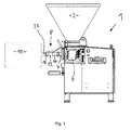
- a filling machine 1 in a side view device for filling pasty masses, also referred to as a filling machine 1, is designed as a vacuum filling machine and is used for filling sausage meat. Among other things, it has a funnel-shaped storage container 2 for receiving and storing the sausage meat or other pasty mass such as dough.
- a filling pump not shown, conveys the pasty mass into a filling tube 4 or filling tube holder 4 for dispensing the mass from the filling machine 1.
- the filling tube 4 has at its free end on an external thread.
- the filling machine 1 can be controlled.
- a device 8 for processing the pasty mass is coupled in the exemplary embodiment of the filling machine 1, but it could also be coupled to another pump for conveying a pasty food mass or be connected to a line through which the pasty mass is conveyed through.
- the processing device 8, also in the Fig. 2 and 3 shown generally serves to process the mass flowing therethrough. Especially in the exemplary embodiment, it serves for the finer distribution of gas inclusions, in particular air intakes within the sausage meat with the aid of insertable nozzles, which is described in more detail below. But you could also make other processing of the sausage meat by means of an insert, for example, a mixture.
- a so-called attachment 10 is connected downstream, which is in the embodiment, a so-called Clipper for dividing and closing individual sausage portions. It could also alternatively be designed as Gearstromteiler, Wolf or the like.
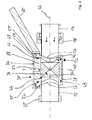
- the processing device 8 has a housing 12 and two attached thereto, opposite pipe socket 14, 16, with the free ends of a coupling to the filling machine 1 and the attachment 10 is made so that the mass of the filling machine 1 in the processing device 8 and from there into the attachment 10 can be promoted.
- the coupling is realized by screw connections with the help of union nuts and external threads.
- a union nut 18 is formed on the pipe socket 14 for establishing a connection with an external thread on the filling tube 4.
- an external thread 20 is provided, which with a pipe socket 22 (FIG. Fig. 1 ) of the attachment 10 by means of another union nut (not shown) is connectable.
- the pipe socket 14,16 housing 12 disposed between the pipe socket 14,16 housing 12 at one end of the pipe socket 14 an inlet 24 for introducing the mass into the interior of the housing 12 and a coincident with one end of the pipe socket 16 outlet 26 for discharging the mass from the housing 12 on.
- the welded or screwed to the pipe socket 14, 16 housing 12 has substantially the shape of a cylindrical tube or pipe section, the lower end with a closure plate 28 permanently closed is.
- the housing 12 has a closable opening 30 by means of a closure and a thread 32 on the outside.
- a one-piece receiving device 34 serves to receive an insert 36, in the embodiment in the form of a nozzle 37, which influences the mass flowing therethrough.
- the receiving device 34 has an upper closure portion 38, which in the in FIG. 3 shown assembled state, the opening 30 of the housing 12 completely closes, and a lower receiving portion 40 which receives the nozzle 37 and protrudes in the mounted state largely into the interior of the housing 12.
- Receiving device 34 and the insert 36 in the form of the nozzle 37 are together through the opening in - in the substantially radial direction - used so that the nozzle 37 can be flowed through by the mass.
- the insert 36 is positioned within the housing 12.
- the substantially cylindrical, tubular receiving portion 40 is arranged concentrically to the longitudinal axis 41 of the housing 12.
- the rotationally symmetrical nozzle 37 is arranged with its longitudinal axis 43, which is also the longitudinal axis of the pipe socket 14 and 16, substantially perpendicular to the longitudinal axis 41 of the housing 12 and coaxial with the two pipe sockets 14, 16.
- a cylindrical bore 42 in which the outer cylindrical nozzle 37 is inserted, formed, and a stop 44 in the form of a shoulder, which serves that the nozzle 37 in the inserted state there comes to rest, wherein it is completely disposed within the bore 42.
- the nozzle 37 is conically tapering on the inside in some sections and sections are widened in a conically widening manner in the flow direction of the mass.
- the wall of the receiving portion has at opposite wall portions in each case a through-bore 42, so that the insert 36 can be inserted and positioned simultaneously.
- the closure portion 38 is formed as a substantially circular closure plate which completely closes the opening 30.
- an O-ring 48 is used for sealing.
- an O-ring 49 By means of an O-ring 49, a further seal is realized.
- slightly rounded outside projections 50 are formed, which come in the assembled state at the upper edge of the housing 12 to the plant.
- a blind bore 52 is centrally formed in the closure plate, which is provided with an internal thread, so that a handling tool can be screwed with an external thread in order to be able to use the receiving device 34 together with the insert 38 Insertion in the direction of the longitudinal axis 41 and opposite to pull out.
- a cap nut 54 is screwed onto the external thread 32 on the housing 12 so that the receiving device 34 is secured in the assembled state in the in FIG. 3 shown position.
- the cap nut has an internal thread 56, an opening and inwardly projecting three uniformly spaced projections 58 which cooperate with the projections 50.
- a radially and slightly upwardly angled projecting straight cylindrical handle 60 is used for manual rotation of the nut 54 in its tightened closed position or an open position in which the projections 58 are not arranged in alignment with the projections 50. In this position, the entire receiving device 34 can be pulled out with insert 36.
- FIG. 2 shows a cylindrical pin 62 ensures that the inserted receiving device 34 is non-rotatably positioned with respect to the longitudinal axis 41.
- the pin 62 is pressed into a cylindrical recess 64 in the housing 12.
- a cylindrical bore 66 is formed, into which the pin 62 can dip.
- the operation of the filling machine 1 and the processing device 8 is as follows:
- a matching to the mass to be processed and the operating conditions nozzle 37 is first inserted into the bore 42 until it comes to rest on the stop 44. The entire receptacle with inserted nozzle 37 is then fully inserted through the opening 30 in the housing 12. Subsequently, the nut 54 is rotated by turning the handle 60 so that it is tightened. Subsequently, the filling machine 1 can be switched on, so that meat in the direction of the arrows, FIG. 3 is conveyed through the pipe socket 14 and through the inner free conically tapered and then widening flow cross section of the nozzle 37, so that there is a distribution of any air inclusions within the sausage meat. Further, the sausage meat flows through the pipe socket 16 in the attachment 10.
- the union nut 54 is loosened, the receiving device 34 is pulled out together with the nozzle 37, another adapted nozzle 37 with another flow cross-section is inserted into the bore 42 and then the entire receiving device 34 is inserted back into the housing as described above.
Landscapes
- Engineering & Computer Science (AREA)
- General Engineering & Computer Science (AREA)
- Life Sciences & Earth Sciences (AREA)
- Mechanical Engineering (AREA)
- Wood Science & Technology (AREA)
- Zoology (AREA)
- Food Science & Technology (AREA)
- Processing Of Meat And Fish (AREA)
Applications Claiming Priority (1)
| Application Number | Priority Date | Filing Date | Title |
|---|---|---|---|
| DE202008016702U DE202008016702U1 (de) | 2008-12-18 | 2008-12-18 | Vorrichtung zum Abfüllen bzw. Bearbeiten von pastösen Massen insbesondere Wurstbrät |
Publications (2)
| Publication Number | Publication Date |
|---|---|
| EP2198717A2 true EP2198717A2 (fr) | 2010-06-23 |
| EP2198717A3 EP2198717A3 (fr) | 2012-09-19 |
Family
ID=42078019
Family Applications (1)
| Application Number | Title | Priority Date | Filing Date |
|---|---|---|---|
| EP09179835A Withdrawn EP2198717A3 (fr) | 2008-12-18 | 2009-12-18 | Dispositif de remplissage ou de traitement de masses pâteuses, notamment chaire à saucisse |
Country Status (3)
| Country | Link |
|---|---|
| US (1) | US20100199862A1 (fr) |
| EP (1) | EP2198717A3 (fr) |
| DE (1) | DE202008016702U1 (fr) |
Cited By (2)
| Publication number | Priority date | Publication date | Assignee | Title |
|---|---|---|---|---|
| EP2468106A1 (fr) * | 2010-12-22 | 2012-06-27 | Albert Handtmann Maschinenfabrik GmbH & Co. KG | Dispositif et procédé de répartition d'air résiduel dans des masses pâteuses, notamment pour la fabrication de saucisses |
| DE202018105163U1 (de) | 2018-09-10 | 2018-09-18 | Albert Handtmann Maschinenfabrik Gmbh & Co. Kg | Vorrichtung zur Feinverteilung von Luftanteilen in pastösen Massen |
Families Citing this family (2)
| Publication number | Priority date | Publication date | Assignee | Title |
|---|---|---|---|---|
| EP3453260A1 (fr) * | 2017-09-06 | 2019-03-13 | 3vM Beteiligungsgesellschaft | Procédé de fabrication de saucisse |
| DE102020113660B4 (de) * | 2020-05-20 | 2022-12-22 | Vemag Maschinenbau Gmbh | Teig-Behandlungseinheit, sowie Vorrichtung und Verfahren zum Behandeln von Teig |
Family Cites Families (20)
| Publication number | Priority date | Publication date | Assignee | Title |
|---|---|---|---|---|
| DE294374C (fr) * | ||||
| US1698314A (en) * | 1923-11-09 | 1929-01-08 | Bailey Meter Co | Flow meter |
| US1972151A (en) * | 1932-02-26 | 1934-09-04 | Crane Co | Controlled flow plug valve |
| US2076465A (en) * | 1935-11-13 | 1937-04-06 | Kirk Corp | Flow bean |
| US2111463A (en) * | 1936-06-15 | 1938-03-15 | Dakota Theodore Smith | Mechanical force feeder for food choppers and grinders |
| US2836199A (en) * | 1955-05-09 | 1958-05-27 | United States Steel Corp | Orifice plate mounting |
| FR1422912A (fr) * | 1964-10-13 | 1966-01-03 | Haut Rhin Manufacture Machines | Perfectionnements aux techniques de fabrication des saucisses et produits analogues |
| US3474818A (en) * | 1966-05-02 | 1969-10-28 | Ralph E Hartman | Combined plug and check valve |
| US3484078A (en) * | 1966-07-01 | 1969-12-16 | Norman H Haenky | Valve |
| WO1991002183A1 (fr) * | 1989-08-07 | 1991-02-21 | Graves John G | Vanne combinee |
| US5004005A (en) * | 1989-08-07 | 1991-04-02 | Graves John G | Combination valve |
| US4989631A (en) * | 1990-05-14 | 1991-02-05 | Harbin Roy W | Valve device with control sleeve and check valve |
| US5881996A (en) * | 1995-08-28 | 1999-03-16 | Stockham Valves & Fittings, Inc. | Valve plug |
| US5937906A (en) * | 1997-05-06 | 1999-08-17 | Kozyuk; Oleg V. | Method and apparatus for conducting sonochemical reactions and processes using hydrodynamic cavitation |
| DE29718684U1 (de) * | 1997-10-22 | 1999-02-25 | Vemag Maschinen & Anlagenbau Gmbh | Darmfüllvorrichtung sowie Maschine zum Füllen von Wurst-Därmen |
| US6016742A (en) * | 1998-12-18 | 2000-01-25 | Wenger Manufacturing, Inc. | Short length tapered extrusion cooking apparatus having peripheral die |
| US20040099145A1 (en) * | 2002-11-26 | 2004-05-27 | Good Humor-Breyers Ice Cream | Orifice modifier |
| US7188578B2 (en) * | 2005-03-29 | 2007-03-13 | Derosa Robert James | Cover plate removal tool |
| DK1832176T3 (da) * | 2006-03-09 | 2009-03-16 | Handtmann Albert Maschf | Indretning til regulering af fyldstand og til reguleret evakuering af pastöse masser |
| US8764731B2 (en) * | 2009-10-02 | 2014-07-01 | Medline Industries, Inc. | Connector for fluid conduit with integrated luer access port |
-
2008
- 2008-12-18 DE DE202008016702U patent/DE202008016702U1/de not_active Expired - Lifetime
-
2009
- 2009-12-18 US US12/641,365 patent/US20100199862A1/en not_active Abandoned
- 2009-12-18 EP EP09179835A patent/EP2198717A3/fr not_active Withdrawn
Non-Patent Citations (1)
| Title |
|---|
| None |
Cited By (3)
| Publication number | Priority date | Publication date | Assignee | Title |
|---|---|---|---|---|
| EP2468106A1 (fr) * | 2010-12-22 | 2012-06-27 | Albert Handtmann Maschinenfabrik GmbH & Co. KG | Dispositif et procédé de répartition d'air résiduel dans des masses pâteuses, notamment pour la fabrication de saucisses |
| US9433222B2 (en) | 2010-12-22 | 2016-09-06 | Albert Handtmann Maschinenfabrik Gmbh & Co. Kg | Device and method for distributing residual air in pasty masses, in particular for the production of sausages |
| DE202018105163U1 (de) | 2018-09-10 | 2018-09-18 | Albert Handtmann Maschinenfabrik Gmbh & Co. Kg | Vorrichtung zur Feinverteilung von Luftanteilen in pastösen Massen |
Also Published As
| Publication number | Publication date |
|---|---|
| DE202008016702U1 (de) | 2010-06-02 |
| US20100199862A1 (en) | 2010-08-12 |
| EP2198717A3 (fr) | 2012-09-19 |
Similar Documents
| Publication | Publication Date | Title |
|---|---|---|
| EP1925370B1 (fr) | Cartouche à plusieurs composants | |
| EP0302819B1 (fr) | Magasin de cartouche pour substances coulantes | |
| DE102010019222B4 (de) | Austragsvorrichtung für Kartuschen | |
| EP2218331B1 (fr) | Appareil de mélange pour masses alimentaires telles que de la chair à saucisses ainsi que machine de bourrage | |
| DE102010019224B3 (de) | Austragsvorrichtung für pastöse Massen | |
| DE1482692A1 (de) | Fassanzapfvorrichtung | |
| WO2007039612A1 (fr) | Dispositif de dosage pour substances pulverulentes ou pateuses | |
| CH670580A5 (fr) | ||
| WO2013000524A1 (fr) | Pistolet-pulvérisateur facile à nettoyer, accessoires pour ce pistolet-pulvérisateur, procédé de montage et de démontage | |
| EP1931952A1 (fr) | Dispositif de dosage pour substances pulverulentes ou pateuses | |
| EP2747900A1 (fr) | Mélangeur et dispositif de distribution | |
| EP2198717A2 (fr) | Dispositif de remplissage ou de traitement de masses pâteuses, notamment chaire à saucisse | |
| EP2369943B1 (fr) | Pièce de liaison | |
| DE1930151B2 (de) | Auslassvorrichtung an einer bolzenzufuehrungsvorrichtung | |
| EP2100513B1 (fr) | Dispositif de transport et de traitement d'aliments | |
| DE102009037346B4 (de) | Einbauwerkzeug und Verfahren zum Einbau eines Drahtgewindeeinsatzes | |
| EP1733785B1 (fr) | Appareil et set pour mélanger un solide pulvérulent ou un liquide avec un liquide | |
| DE102012003390B4 (de) | Kartuschensystem und statischer Mischer hierfür | |
| DE102011100597B4 (de) | Manuell höhen- und neigungseinstellbare Auslaufschale | |
| DE102017115845B4 (de) | Milchschäumgerät | |
| EP3095528B1 (fr) | Dispositif de sortie pour masses pateuses | |
| DE4400312A1 (de) | Trenn-Schneidsatz für Fleischwolf | |
| DE10332391B4 (de) | Vorrichtung zur Flüssigfütterung von Nutztieren, insbesondere Schweinen | |
| DE19713650C1 (de) | Rührwerkzeug | |
| DE10336337A1 (de) | Aufsatz für Tuben, Kartuschen oder Dosen |
Legal Events
| Date | Code | Title | Description |
|---|---|---|---|
| PUAI | Public reference made under article 153(3) epc to a published international application that has entered the european phase |
Free format text: ORIGINAL CODE: 0009012 |
|
| AK | Designated contracting states |
Kind code of ref document: A2 Designated state(s): AT BE BG CH CY CZ DE DK EE ES FI FR GB GR HR HU IE IS IT LI LT LU LV MC MK MT NL NO PL PT RO SE SI SK SM TR |
|
| PUAL | Search report despatched |
Free format text: ORIGINAL CODE: 0009013 |
|
| AK | Designated contracting states |
Kind code of ref document: A3 Designated state(s): AT BE BG CH CY CZ DE DK EE ES FI FR GB GR HR HU IE IS IT LI LT LU LV MC MK MT NL NO PL PT RO SE SI SK SM TR |
|
| RIC1 | Information provided on ipc code assigned before grant |
Ipc: A22C 11/02 20060101AFI20120813BHEP |
|
| 17P | Request for examination filed |
Effective date: 20130319 |
|
| STAA | Information on the status of an ep patent application or granted ep patent |
Free format text: STATUS: REQUEST FOR EXAMINATION WAS MADE |
|
| STAA | Information on the status of an ep patent application or granted ep patent |
Free format text: STATUS: THE APPLICATION IS DEEMED TO BE WITHDRAWN |
|
| D17P | Request for examination filed (deleted) | ||
| 18D | Application deemed to be withdrawn |
Effective date: 20130320 |