EP2198683B1 - System für die automatische Verteilung von Partikeln für landwirtschaftlichen Maschinen, Verfahren und entsprechendes Modul - Google Patents
System für die automatische Verteilung von Partikeln für landwirtschaftlichen Maschinen, Verfahren und entsprechendes Modul Download PDFInfo
- Publication number
- EP2198683B1 EP2198683B1 EP09178557A EP09178557A EP2198683B1 EP 2198683 B1 EP2198683 B1 EP 2198683B1 EP 09178557 A EP09178557 A EP 09178557A EP 09178557 A EP09178557 A EP 09178557A EP 2198683 B1 EP2198683 B1 EP 2198683B1
- Authority
- EP
- European Patent Office
- Prior art keywords
- opening
- control
- closing
- particle
- guide bar
- Prior art date
- Legal status (The legal status is an assumption and is not a legal conclusion. Google has not performed a legal analysis and makes no representation as to the accuracy of the status listed.)
- Active
Links
- 239000002245 particle Substances 0.000 title claims abstract description 78
- 238000009826 distribution Methods 0.000 title claims abstract description 51
- 238000000034 method Methods 0.000 title claims abstract description 20
- 238000006243 chemical reaction Methods 0.000 claims abstract description 13
- 238000003892 spreading Methods 0.000 claims description 45
- 230000007480 spreading Effects 0.000 claims description 45
- 239000007921 spray Substances 0.000 claims description 21
- 238000005520 cutting process Methods 0.000 claims description 9
- 238000009331 sowing Methods 0.000 claims description 4
- 238000001514 detection method Methods 0.000 claims description 3
- 235000013339 cereals Nutrition 0.000 claims description 2
- 230000007257 malfunction Effects 0.000 claims 1
- 239000003337 fertilizer Substances 0.000 description 18
- 230000001276 controlling effect Effects 0.000 description 16
- 238000005507 spraying Methods 0.000 description 9
- 239000007787 solid Substances 0.000 description 7
- 239000000047 product Substances 0.000 description 6
- 230000006978 adaptation Effects 0.000 description 3
- 238000010276 construction Methods 0.000 description 3
- 230000004048 modification Effects 0.000 description 3
- 238000012986 modification Methods 0.000 description 3
- 238000012545 processing Methods 0.000 description 3
- 241000238876 Acari Species 0.000 description 2
- IJGRMHOSHXDMSA-UHFFFAOYSA-N Atomic nitrogen Chemical compound N#N IJGRMHOSHXDMSA-UHFFFAOYSA-N 0.000 description 2
- 230000004913 activation Effects 0.000 description 2
- 238000013459 approach Methods 0.000 description 2
- 230000008859 change Effects 0.000 description 2
- 238000010586 diagram Methods 0.000 description 2
- 201000010099 disease Diseases 0.000 description 2
- 208000037265 diseases, disorders, signs and symptoms Diseases 0.000 description 2
- 230000000694 effects Effects 0.000 description 2
- 230000000750 progressive effect Effects 0.000 description 2
- 230000035484 reaction time Effects 0.000 description 2
- 230000009467 reduction Effects 0.000 description 2
- 150000003839 salts Chemical class 0.000 description 2
- 238000009966 trimming Methods 0.000 description 2
- 238000005303 weighing Methods 0.000 description 2
- 241000221785 Erysiphales Species 0.000 description 1
- 244000098338 Triticum aestivum Species 0.000 description 1
- 230000000903 blocking effect Effects 0.000 description 1
- 230000008878 coupling Effects 0.000 description 1
- 238000010168 coupling process Methods 0.000 description 1
- 238000005859 coupling reaction Methods 0.000 description 1
- 230000007547 defect Effects 0.000 description 1
- 238000011161 development Methods 0.000 description 1
- 238000006073 displacement reaction Methods 0.000 description 1
- 230000007613 environmental effect Effects 0.000 description 1
- 239000012263 liquid product Substances 0.000 description 1
- 238000004519 manufacturing process Methods 0.000 description 1
- 239000000463 material Substances 0.000 description 1
- 230000007246 mechanism Effects 0.000 description 1
- 229910052757 nitrogen Inorganic materials 0.000 description 1
- 238000005457 optimization Methods 0.000 description 1
- 210000000056 organ Anatomy 0.000 description 1
- 235000012830 plain croissants Nutrition 0.000 description 1
- 230000001737 promoting effect Effects 0.000 description 1
- 238000011084 recovery Methods 0.000 description 1
- 230000001105 regulatory effect Effects 0.000 description 1
- 238000003860 storage Methods 0.000 description 1
Images


Classifications
-
- A—HUMAN NECESSITIES
- A01—AGRICULTURE; FORESTRY; ANIMAL HUSBANDRY; HUNTING; TRAPPING; FISHING
- A01C—PLANTING; SOWING; FERTILISING
- A01C17/00—Fertilisers or seeders with centrifugal wheels
- A01C17/006—Regulating or dosing devices
-
- A—HUMAN NECESSITIES
- A01—AGRICULTURE; FORESTRY; ANIMAL HUSBANDRY; HUNTING; TRAPPING; FISHING
- A01B—SOIL WORKING IN AGRICULTURE OR FORESTRY; PARTS, DETAILS, OR ACCESSORIES OF AGRICULTURAL MACHINES OR IMPLEMENTS, IN GENERAL
- A01B79/00—Methods for working soil
- A01B79/005—Precision agriculture
-
- A—HUMAN NECESSITIES
- A01—AGRICULTURE; FORESTRY; ANIMAL HUSBANDRY; HUNTING; TRAPPING; FISHING
- A01C—PLANTING; SOWING; FERTILISING
- A01C17/00—Fertilisers or seeders with centrifugal wheels
- A01C17/006—Regulating or dosing devices
- A01C17/008—Devices controlling the quantity or the distribution pattern
-
- A—HUMAN NECESSITIES
- A01—AGRICULTURE; FORESTRY; ANIMAL HUSBANDRY; HUNTING; TRAPPING; FISHING
- A01C—PLANTING; SOWING; FERTILISING
- A01C21/00—Methods of fertilising, sowing or planting
- A01C21/005—Following a specific plan, e.g. pattern
Definitions
- the field of the invention is that of the distribution of particles for agriculture, that is to say products in a granular form, including solid fertilizer or seeds.
- the invention relates to the control of the particle distribution provided by an agricultural machine, and in particular the optimization of the distribution in the areas near the border, a tip or the end of a field to be treated .
- FIG. 1 An example of a machine for spreading solid fertilizer or sowing on a crop plot is schematically illustrated on the figure 1 . It is in the form of a tractor 10 equipped with a hopper 11 containing fertilizer or seeds 14 to be spread.
- the bottom of the hopper 11 comprises two openings, then two adjustable feeding devices, then two fertilizer distribution adjusting devices, for example in the form of chutes 13 (only one being shown), allowing particles contained 14 in the hopper 11, and placed in overhang of two distributors each comprising a rotating disk 15 carrying projection blades.
- the discs 15 are most often arranged in a substantially horizontal position and their rotation about a substantially vertical axis 16 ensures the projection of the content 14 of the hopper by centrifugal effect, in the form of a sheet, in the general shape of a crescent , extending at the back of the spreading machine.
- the two rotating discs rotate in opposite directions with respect to each other, which makes it possible to spread fertilizer and / or seedling over a large width, typically between 5 and 50 meters.
- Such spreading machines make it possible to treat a parcel of arable land, or field, most often following a predefined path of return / return on it but also with non-imposed trajectories (for example for spreading on meadow).
- the operator of the machine can adapt certain spreading settings, such as, depending on the case, the quantity or weight of particles distributed, the shape of the spreading sheet, and in particular its width, ... It can moreover selectively opening or closing the feed device 13, so as to optimize the amounts of particles spread, especially at the headland, edge, end or field peak.
- overdose is not only expensive, but also harmful.
- overdose of N on soft wheat promotes lodging, reduces nitrogen efficiency by promoting its early storage in unproductive organs, and promotes the early development of diseases such as dumped mites or mites. powdery mildew. This is also in contradiction with the environmental requirements.
- the invention therefore aims to overcome these disadvantages of the prior art.
- an object of the invention is to propose a technique that makes it possible, simply and inexpensively, to improve, that is to say, optimize, the spreading of particles, such as solid fertilizers. or seeds, particularly at the edges, at the ends and at the ends of the field
- the invention aims, according to the embodiments, is to allow the implementation of a reasoned agriculture, reducing and optimizing the use of fertilizers, reducing the risk and some diseases, ...
- the invention also aims to improve the working comfort of the driver, and increase its safety and efficiency, including allowing him to focus on driving.
- Another object of the invention is to provide a technique that can be implemented with materials of different origins, and does not require heavy or specific mechanical or computer means.
- an object of the invention is to allow the use of conventional distributors, whose trays are driven by the PTO of the tractor.
- an agricultural machine particle distribution system comprising at least two particle distributors each equipped with at least a feed device whose opening and closing are controlled by a first actuator, cooperating with a spray management assembly, controlling sprayers and comprising a guide bar fed by geolocation means and cut-off means , receiving control signals of the opening and / or closing of said sections.
- the invention eliminates the implementation of a dedicated, heavy and expensive system for automating the spreading of particles. Indeed, few adaptations are necessary on most distributors, who are already equipped with hatches. Similarly, the invention exploits information provided by a guide bar (this term may include, in the claims, the guide bar itself and the associated section cutting means) conventional, and it is accordingly not necessary to provide geolocation means and specific processing means.
- the invention is therefore based on the adaptation and conversion of signals, originally intended for a spray boom, and produced by a guide bar, into commands for actuators dedicated to particle distribution means, such as a spreader.
- the characteristics of an area covered by a sprayer are very different from the shape of a particle spreading sheet and its distance from the tractor.
- Specific parameterization information available for example in the form of charts detailing the spreader-specific values to be set in the guidance bar (for example: forward / backward / right / left distance, reaction time, recovery rate ).
- the invention proposes to "lure" the guide bar, in order to control a particle distributor using commands in principle dedicated to a sprayer.
- system of the invention also comprises means for manually controlling the opening and closing of said feed devices.
- the driver can then act on the distribution manually, if necessary, independently of commands issued by the system.
- each power device can be open (maximum opening) or closed (total closure).
- said system comprising a device for adjusting the width of the distribution, said autonomous module is able to deliver a total or partial opening command and a total or partial closure command, and can control actuators secondary devices acting on said distribution width adjustment devices.
- the system may comprise means for selectively connecting a bundle of cables coming from said guide bar on the one hand to means for controlling said sprayers, and on the other hand to said autopilot module.
- said conversion means associates with a control signal opening or closing sections a control command of a quantity of particles to be supplied to each distributor.
- the position of the chute can make it possible to move the spreading zone, with respect to the tractor, and / or to modify its surface.
- said particles may in particular belong to the group comprising solid fertilizers, seedlings, slug products, salt, gravel.
- the particle distribution system may comprise, or cooperate with, weighing means of said particles, a speed sensor, ...
- system may comprise, or cooperate with, means for selectively implementing a clipping blade on each of said distributors, configured to change the shape of the spread sheet.
- the invention also relates to the autonomous modules for automatically controlling the particle distribution used in an agricultural machine particle distribution system comprising at least two particle distributors each equipped with at least one feed device of which the opening and closing are controlled by a first actuator.
- This module controls the opening and closing of said supply devices as a function of control signals delivered by an assembly comprising a guide bar supplied by geolocation means and means for cutting off sections, and intended to control sprayers. and comprising means for converting said control signals into opening and closing commands of said first actuators.
- this method also comprises a preliminary step of adjusting said guide bar, in which the parameters normally intended for the control of sprayers are adapted to a particle spreading sheet or to a distribution sheet of a seed drill, for example example a grain drill.
- the method comprises a step of controlling the opening of said dispensing devices, so that it can take at least one intermediate opening position, and / or the position of a chute , so as to modify an average ejection angle according to said control signals.
- the invention is based in particular on the use of a guide bar (this term may include, in the claims, the guide bar itself and the associated section cutting means) for controlling a sprayer , to a particle spreading system (especially solid fertilizer or sowing).
- a guide bar this term may include, in the claims, the guide bar itself and the associated section cutting means
- a particle spreading system especially solid fertilizer or sowing.
- the cuts of sections for sprayer are well known, for more than 20 years, and the solution of the invention can adapt to all the guide bars currently marketed with its section cuts.
- the Figure 2A illustrates, schematically, a tractor 21 equipped with a spray boom 22, comprising a plurality of sections 23, each making it possible to cover a substantially triangular surface 24, so that the overall covered surface is substantially homogeneous and of substantially rectangular shape .
- the tractor 21 is therefore equipped with cut-off means of the spray boom sections 23, which are increasingly common on farms.
- An example of such automatic control means is the "Accuboom" (registered trademark) system.
- the invention thus proposes a simple and effective solution for reusing and adapting these automatic piloting means to the spreading of particles, as illustrated by FIG. Figure 2B .
- the tractor 21 no longer carries a spray boom 22, but means for dispensing particles 25, for example granulated fertilizers or seedlings. It is equipped with two distributors supplying two discs 26 1 and 26 2 , which project the particles respectively onto surfaces 27 1 and 27 2 , together defining a cover surface 27, 5 to 20 m away from the distribution means 25 , and defining a general crescent shape.
- the information provided by the guide bar is used by means of controlling the sections of the spray boom, after having firstly adapted the parameterization and, secondly, transformed the signals, way they can control actuators, such as electric cylinders for example.
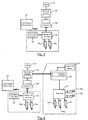
- conventional equipment for the control of a spray boom comprises geolocation means 31, generally in the form of an antenna placed on the tractor and a GPS module.
- a guide bar 32 which delivers information, depending on the geolocation, to means 33 for cutting sections of the spray boom ("Accuboom" for example).
- a module 35 for controlling the opening and closing of the feed devices by example traps, providing the supply of particles of disks 26 1 and 26 2 .
- This module 35 may include in particular double relays, allowing the actuation of electric cylinders 36 1 and 36 2 .
- These cylinders 36 1 and 36 2 are preferably fast cylinders, allowing almost instantaneous opening and closing of the hatches, so that the beginning or the interruption of the spreading is also almost instantaneous. If necessary, it is possible to set a reaction time of the actuators, to anticipate the opening or closing.
- the electronic means 35 furthermore comprise end-of-stroke detection means for the actuators, or more generally actuators, (to interrupt their supply when they have reached the end of the opening or closing stroke) and means for detection of anomaly or failure in its cylinders.
- a manual control box 37 may be provided, so as to allow the user to force the implementation of the actuators 36 1 and 36 2 , and therefore the opening or closing of the corresponding hatches, if necessary, and independently of the commands generated by the means 33 for controlling the spray bars.
- the guide bar 32 can be connected directly to an adjustment and control module 43 (for example of the "Vision” type (registered trademark) distributed by the holder of the present patent application), which can itself be powered by different sensors, and in particular by a speed sensor 44 (speed information which can advantageously be delivered directly by the guide bar), a weighing sensor ...
- an adjustment and control module 43 for example of the "Vision” type (registered trademark) distributed by the holder of the present patent application
- a speed sensor 44 speed information which can advantageously be delivered directly by the guide bar
- a weighing sensor ...
- This housing 43 is connected to second actuators 48 1 and 48 2 , via an electrical harness 47.
- These second actuators 48 1 and 48 2 make it possible to manage the flow rate as a function of the speed of advance and / or Hopper weight ... These are low speed, high precision actuators, while the module 35 acts on the first actuators 36 1 and 36 2 , faster.
- the piloting of the first actuators from the control information of the sections is not trivial. Indeed, the number of sections (typically 6, 8, 10 or more) is distinct from the number of first actuators (one per disk, or two), and the resulting layers are very different.
- the housing 43 may control, via additional actuators 48 3 , 48 4 , the setting of the feed point associated with each disk, so as to modify the shape of the web, and therefore its width, in relation to the information received by the cutoff means 33. It is also possible to control the speed and / or inclination of the disk, for example, to modify the position of the web relative to tractor.
- the housing 43 may, in a particular embodiment, control, by means of an additional actuator 48, the implementation of a clipping blade associated with at least one of the disks, so as to modify the shape of the spreading sheet, especially at the edge of the field.
- a clipping blade is known as "Tribord” (registered trademark), distributed by the holder of the present patent application.
- the figure 5 illustrates, in more detail, the new elements of the invention, in the embodiment of the figure 3 . More specifically, the figure 5 illustrates the dotted framed part of the figure 3 .
- connection means 51 to the cutoff means 33 sections (and / or the draw bar 32, according to the embodiments).
- connection means 51 may be variable, depending on the different manufacturers of guide bar.
- the means for implementing the invention may be designed to have various connectors or adapters, so that all the elements of the figure 5 can be implemented independently of the origin of the guide bar.
- the system includes, of course, means 52 for connection to a power supply, for example 12 volts corresponding to the battery of the tractor.
- LEDs can be associated with the three buttons to indicate the status of the actuators, and be lit to signal an alarm, in case of problems.
- This manual control box 54 is connected via a connector 55 to the electronic module 56.
- This module 56 has two outputs 57 1 , 57 2 , driving the cylinders 36 1 , 36 2 , through double relays.
- the module 56 is therefore adapted to transform the received signals into relay commands, to take into account the manual controls, and to ensure safety, notably by managing the limit switches of the cylinders (and by interrupting the power supplies of the cylinders at the end of the race). and detecting potential problems, such as inadvertent blocking of a cylinder.
- the Figures 6A and 6B schematically illustrate a mechanism for opening the hatches controlled by a jack, according to one embodiment of the invention. More specifically, the Figure 6A has a hatch 61 for feeding one of the disks, in the closed position. In this position, the hatch 61 closes the supply of one of the disks.
- the actuator 36 acts, by its end 361, on the hatch 61, mounted to rotate about an axis 65, to control the closing of the supply.
- Springs may be provided, to assist the movement of the hatch and / or maintain it in a desired position.
- a spring (not shown) returns the hatch to the open position when the end 61 of the jack is raised.
- the Figure 6B illustrates the system of fig 6A in the open position. In this position, the cylinder 36 is in a folded position, and it is found that the end 361 is raised, having simultaneously released the hatch 61, which has pivoted about the axis 65, to release the feed opening.
- the particles can then flow from the dispenser to the disc.
- the figure 7 presents in a simplified way a block diagram of the method of implementation of the invention.
- the guide bar is programmed, so as to take into account the particular settings of the spreading of particles, and in particular the position and shape of the sheet (see FIG. Figure 2B ).
- this adjustment step we will introduce information to take into account the width of the spreading sheet, or spreading width, the distance between the position of the GPS antenna and the heart of the sheet generated by each disk, and optionally a desired percentage of coverage, especially in the field tip.
- the number of sections is also regulated, for example by setting it to two (in the case of an all-or-nothing operation).
- the distance between the position of the GPS antenna and the core of the sheet generated by each disk may, for example, be between 5 and 20 meters towards the rear of the tractor, and between 3 and 15 meters on the side, for take into account the centrifugal projection of the device.
- the distance between the coupling of the distributor and the core of each sheet may be an average value, variable according to the working width and the type of blade used. This information can therefore be specified, for example also in charts.
- the spreading (more generally the distribution, according to the type of particles) 73, is implemented with the system of the invention.
- the module of the invention receives (731) the control signals delivered by the guide bar and the section cutoff means, converts (732) these signals, to control (733) the opening and closing of dispensing devices (and more generally, if necessary, the degree of opening and possibly other settings).
- the flow trap closes automatically ( Figure 6A ) when the coverage of the layers reaches the limit threshold initially programmed.
- the solution of the invention therefore makes it possible to equip a series distributor, with or without particular electronics, whose discs or trays are driven by the PTO of the tractor by means of conventional angle references. It exploits the information of the guide bars available on the market.
- a system automating the cuts and reopening of the flow rate during inputs of granular fertilizer or seedling, grafting on equipment potentially already present on a tractor, including the bar guide, the GPS antenna and the section management system.
- the invention makes it possible to improve the productivity of the work, and to optimize optimally the input (fertilizer for example) source of diffuse pollution, and expensive product.
- the invention also makes it possible to homogenize the productivity of a plot.
- the invention has in particular been described for application to the spreading of a solid fertilizer. It is clear however that it can be applied to the distribution of other types of particles, for example seedlings, slug products, salt, gravel.
- a drill it can actuate a cylinder closing half of the drill, reduce the dose of 50% in the tips, and / or cut the electric motor in the field ends.
- the guide bar controls 6 spraying sections, and thus delivers 6 separate control signals (binary) opening or closing.
- these 6 control signals will be converted in order to control the discs of a spreader, in particular the means which make it possible to control their feed, and in particular the shape of the spreading sheet, and the quantity of particles to spread.
- the autonomous module converts the 6 opening signals into maximum opening signals of the two hatches, and the spreading zone 81 is obtained in the form of increasing.
- this chute that adjusts the spreading width.
- This chute transfers the particles from the outlet of the metering orifice to the blades of the disk concerned, which will accelerate them to distribute them on the ground.
- the variation of the position of deposit of the product in the blades displaces the crescent spread on the ground (angular displacement)
- the shape of the spreading sheet thus has a general crescent shape (and not a rectangular shape as is the case for spraying), corresponding to the combination of two croissants generated by each of the disks, and whose respective surfaces are controlled by the adjustment of the chute, for example according to angular parameters ⁇ moyG and ⁇ moyD , corresponding to an average angle of ejection of the fertilizer with respect to the axis of advance 91.
- a stop distribution command complete closure of the particle supply
- a stop command of the right disk A quick closing command of the hatch for the cylinder 36 2 can also be issued.
- the conversion performed by the autonomous module can be as follows: Control signals of the guide bar Dose of the left disc ⁇ moyG Cylinder 36 1 Dose of the right disk ⁇ moyD Cylinder 36 2 111111 100% 30 ° WE 100% -30 ° WE 111110 100% 30 ° WE 66% -25 ° WE 111100 100% 30 ° WE 33% -21 ° WE 111000 100% 30 ° WE 0% -30 ° OFF 110000 66% 35 ° WE 0% -30 ° OFF 100000 33% 42 ° WE 0% -30 ° OFF 000000 0% 30 ° OFF 0% -30 ° OFF 000001 0% 30 ° OFF 33% -42 ° WE 000011 0% 30 ° OFF 66% -35 ° WE 000111 0% 30 ° OFF 100% -30 ° WE 001111 33% 21 ° WE 100% -30 ° WE 011111 66% 25 ° WE 100% -30 ° WE
- control signal delivered by the lightbar is a binary signal of 6 bits, equal to 1 when the corresponding section (by associating a bit with a section, the most significant bit corresponding to the leftmost section). must be open and 0 when it must be closed.
- the number of sections is indicative, and there may be 8, 10 or more sections.
- this control signal thus makes it possible to generate six distinct commands, for the doses of products delivered to each disk, the angles ⁇ moyG and ⁇ moyD , corresponding to an average angle of ejection of the fertilizer with respect to the advance axis 91 and a control of the control cylinders of the feed hatches (ON: open hatch, OFF: closed hatch), and optionally, a command of each engine.
- the treatment may aim at adapting the shape (coverage area) of the sheet and its position, for example by defining polar coordinates, and in particular the angles ⁇ moyG and ⁇ moyd described above.
- the radii R moyG and R moyD distance between the center of the disc and the middle of the corresponding sub-croissant
- This variation can in particular be obtained by modifying the speed of the disc (the radius increases if the speed increases) and / or the inclination of the discs.
Landscapes
- Life Sciences & Earth Sciences (AREA)
- Soil Sciences (AREA)
- Environmental Sciences (AREA)
- Engineering & Computer Science (AREA)
- Mechanical Engineering (AREA)
- Catching Or Destruction (AREA)
- Fertilizing (AREA)
- Agricultural Chemicals And Associated Chemicals (AREA)
- Sowing (AREA)
- Control Of Position, Course, Altitude, Or Attitude Of Moving Bodies (AREA)
Claims (13)
- System für die Verteilung von Partikeln für landwirtschaftliche Maschinen, umfassend mindestens zwei Partikelverteiler, die jeweils mit mindestens einer Zuführvorrichtung versehen sind, deren Öffnen und Schließen durch ein erstes Betätigungsorgan (361, 362) gesteuert werden, dadurch gekennzeichnet, dass es ein autonomes Modul zur automatischen Steuerung des Öffnens und des Schließens der Zuführvorrichtung umfasst, das Steuersignale für das Zerstäuben von einer Einheit, die eine Spurführung (32), welche von Geolokalisierungsmitteln (31) und Mitteln zum Durchführen einer Teilbreitenschaltung (33) gespeist wird und dazu bestimmt ist, Zerstäuber zu steuern, und Mittel zum Konvertieren der Zerstäubungssteuersignale in Steuerbefehle für das Öffnen und Schließen der ersten Betätigungsorgane (361, 362) der Partikelverteiler umfasst.
- System für die Verteilung von Partikeln gemäß Anspruch 1, dadurch gekennzeichnet, dass es weiterhin manuelle Steuermittel für das Öffnen und Schließen der Zuführvorrichtung (361, 362) aufweist.
- System für die Verteilung von Partikeln gemäß einem der Ansprüche 1 bis 2, dadurch gekennzeichnet, dass das autonome Modul (35) in der Lage ist, einen Steuerbefehl zum vollständigen Öffnen, einen Steuerbefehl zum vollständigen Schließen und mindestens einen Steuerbefehl zum teilweise Öffnen jeder der Zuführvorrichtungen auszugeben, um eine Kontrolle über den Partikeldurchsatz zu ermöglichen.
- System für die Verteilung von Partikeln gemäß einem der Ansprüche 1 bis 3, dadurch gekennzeichnet, dass es Mittel zum selektiven Verbinden eines Kabelstrangs (47) aus der Teilbreitenschaltung (33) einerseits mit den Kontrollmitteln der Zerstäuber und andererseits mit dem Modul zum automatischen Steuern umfasst.
- System für die Verteilung von Partikeln gemäß einem der Ansprüche 1 bis 4, dadurch gekennzeichnet, dass das System eine Regelvorrichtung (48) für die Verteilbreite umfasst, wobei das autonome Modul (35) in der Lage ist, einen Steuerbefehl zum vollständigen Öffnen und/oder einen Steuerbefehl zum vollständigen oder teilweisen Schließen auszugeben, wobei das autonome Modul (35) untergeordnete Betätigungsorgane (483, 484), die auf die Regelvorrichtung für die Verteilbreite einwirken, steuern kann.
- Autonomes Modul (35) zum automatischen Steuern der Verteilung von Partikeln für landwirtschaftliche Maschinen, umfassend mindestens zwei Partikelverteiler, die jeweils mit mindestens einer Zuführvorrichtung versehen sind, deren Öffnen und Schließen durch ein erstes Betätigungsorgan (361, 362) gesteuert werden, dadurch gekennzeichnet, dass es das Öffnen und Schließen der Zuführvorrichtung in Abhängigkeit von Zerstäubersteuersignalen steuert, die von einer Spurführung (32) ausgegeben werden, welche von Geolokalisierungsmitteln (31) und Mitteln (33) zum Durchführen einer Teilbreitenschaltung gespeist wird, die dazu dienen, die Zerstäuber zu steuern, und dass es Mittel zum Konvertieren der Zerstäubungssteuersignale in Steuerbefehle zum Öffnen oder Schließen der Betätigungsorgane der Partikelverteiler umfasst.
- Modul zum automatischen Steuern der Verteilung von Partikeln gemäß Anspruch 6, dadurch gekennzeichnet, dass es Mittel zum manuellen Steuern des Öffnens und des Schließens der Zuführvorrichtung umfasst.
- Modul zum automatischen Steuern der Verteilung von Partikeln gemäß einem der Ansprüche 6 bis 7, dadurch gekennzeichnet, dass es Mittel für die Endabschaltung und die Pannendetektion für jedes der Betätigungsorgane aufweist.
- Modul zum automatischen Steuern der Verteilung von Partikeln gemäß einem der Ansprüche 6 bis 8, dadurch gekennzeichnet, dass es Mittel zum Anzeigen der geöffneten bzw. geschlossenen Stellung der Zuführeinrichtungen umfasst und/oder zum Anzeigen der gegenwärtigen Funktionsweise, manuell oder automatisch und/oder das Vorliegen eines Fehlers umfasst.
- Verfahren zum Verteilen von Partikeln unter Verwendung eines Moduls zum automatischen Steuern gemäß einem der Ansprüche 6 bis 9 für eine landwirtschaftliche Maschine, die mindestens zwei Partikelverteiler aufweist, die jeweils mindestens eine Zuführvorrichtung aufweisen, deren Öffnen und Schließen von einem ersten Betätigungsorgan (361, 362) gesteuert werden, gekennzeichnet durch die folgenden Verfahrensschritte :• Empfang von Steuersignalen, die von einer Bahnsteuerung (32) ausgegeben werden, welche von Geolokalisierungsmitteln (31) und Mitteln (33) zum Durchführen einer Teilbreitenschaltung gespeist wird, die dazu dienen, die Zerstäuber zu steuern ;• Konvertieren der Zerstäubungssteuersignale in Steuerbefehle zum Öffnen oder Schließen der ersten Betätigungsorgane (361, 362) ;• Öffnen und/oder Schließen der Klappen in Abhängigkeit von den Steuerbefehlen.
- Verfahren zumn Verteilen von Partikeln gemäß Anspruch 10, dadurch gekennzeichnet, dass es einen ersten Schritt der Regelung der Bahnsteuerung (32) umfasst, in dem die die normalerweise zum Steuern von Zerstäubern bestimmten Parameter auf einen Partikelteppich oder einen Saatgutteppich angepasst werden, beispielsweise auf einen Getreidesaatgutteppich.
- Verfahren zum Verteilen von Partikeln gemäß Anspruch 11, dadurch gekennzeichnet, dass der Schritt der Regelung das Konfigurieren mindestens der folgenden Parameter umfasst :• Breite des Saatgutteppichs ;• Abstand zwischen einer Geolokalisierungsantenne und dem Zentrum des von beiden Scheiben gebildeten Teppichs ;• in einer Feldspitze gewünschter Abdeckungsgrad ;• Vorlaufzeit der Reaktion der ersten Betätigungsorgane (361, 362) ;• Zahl der Teilbreiten.
- Verfahren zum Verteilen von Partikel gemäß einem der Ansprüche 10 bis 12, dadurch gekennzeichnet, dass es einen Schritt des Kontrollierens der Öffnung der Verteilvorrichtungen umfasst, so daß diese in Abhängigkeit von den Steuersignalen zumindest eine teilweise Öffnungsstellung einnehmen können.
Priority Applications (2)
| Application Number | Priority Date | Filing Date | Title |
|---|---|---|---|
| EP11183547A EP2409559B1 (de) | 2008-12-19 | 2009-12-09 | Automatisches Partikelverteilungssystem für eine landwirtschaftliche Maschine und das zugehörige Verfahren |
| PL11183547T PL2409559T3 (pl) | 2008-12-19 | 2009-12-09 | Zautomatyzowany układ do rozprowadzenia cząstek do maszyn rolniczych i odpowiedni sposób |
Applications Claiming Priority (1)
| Application Number | Priority Date | Filing Date | Title |
|---|---|---|---|
| FR0807261A FR2940003B1 (fr) | 2008-12-19 | 2008-12-19 | Systeme automatise de distribution de particules pour machine agricole, module et procede correspondants |
Related Child Applications (1)
| Application Number | Title | Priority Date | Filing Date |
|---|---|---|---|
| EP11183547.6 Division-Into | 2011-09-30 |
Publications (2)
| Publication Number | Publication Date |
|---|---|
| EP2198683A1 EP2198683A1 (de) | 2010-06-23 |
| EP2198683B1 true EP2198683B1 (de) | 2012-02-08 |
Family
ID=40908647
Family Applications (2)
| Application Number | Title | Priority Date | Filing Date |
|---|---|---|---|
| EP11183547A Active EP2409559B1 (de) | 2008-12-19 | 2009-12-09 | Automatisches Partikelverteilungssystem für eine landwirtschaftliche Maschine und das zugehörige Verfahren |
| EP09178557A Active EP2198683B1 (de) | 2008-12-19 | 2009-12-09 | System für die automatische Verteilung von Partikeln für landwirtschaftlichen Maschinen, Verfahren und entsprechendes Modul |
Family Applications Before (1)
| Application Number | Title | Priority Date | Filing Date |
|---|---|---|---|
| EP11183547A Active EP2409559B1 (de) | 2008-12-19 | 2009-12-09 | Automatisches Partikelverteilungssystem für eine landwirtschaftliche Maschine und das zugehörige Verfahren |
Country Status (5)
| Country | Link |
|---|---|
| EP (2) | EP2409559B1 (de) |
| AT (1) | ATE544334T1 (de) |
| DK (1) | DK2198683T3 (de) |
| FR (1) | FR2940003B1 (de) |
| PL (1) | PL2409559T3 (de) |
Cited By (1)
| Publication number | Priority date | Publication date | Assignee | Title |
|---|---|---|---|---|
| EP2798929B1 (de) | 2013-05-03 | 2015-08-19 | Sulky-Burel | Verfahren zur automatischen Parametrisierung einer Kontrollvorrichtung für Arbeitsvorgänge einer Landmaschine, entsprechendes Computerprogramm, entsprechende Steuereinheit und entsprechende landwirtschaftliche Maschine |
Families Citing this family (9)
| Publication number | Priority date | Publication date | Assignee | Title |
|---|---|---|---|---|
| FR2967547B1 (fr) * | 2010-11-18 | 2014-02-07 | Sulky Burel | Dispositif d'epandage centrifuge a goulotte permettant de prendre en compte l'effet debit |
| EP2689649B1 (de) * | 2012-07-26 | 2018-03-21 | Rauch Landmaschinenfabrik Gmbh | Verfahren zur gleichmäßigen Verteilung von Streugut im Übergangsbereich zwischen den Feldfahrgassen und der Grenzfahrgasse eines Feldes sowie Zweischeibenstreuer zur Durchführung eines solchen Verfahrens |
| DE102014106771A1 (de) | 2014-05-14 | 2015-11-19 | Amazonen-Werke H. Dreyer Gmbh & Co. Kg | Verfahren zum Ausbringen von Düngemittel |
| DE102016108176A1 (de) * | 2016-05-03 | 2017-11-09 | Amazonen-Werke H. Dreyer Gmbh & Co. Kg | Steuersystem für eine landwirtschaftliche Maschine und Verfahren |
| DE102017100668A1 (de) * | 2017-01-16 | 2018-07-19 | Amazonen-Werke H. Dreyer Gmbh & Co. Kg | Verfahren zur Ermittlung von Teilbreiten bei einem landwirtschaftlichen Schleuderstreuer |
| US11045827B2 (en) * | 2017-08-14 | 2021-06-29 | Gvm, Inc. | Spreader |
| DE102017120870A1 (de) | 2017-09-11 | 2019-03-14 | Amazonen-Werke H. Dreyer Gmbh & Co. Kg | Verfahren zum Ausbringen von Streugut |
| PL3720264T3 (pl) | 2017-12-07 | 2023-10-30 | Salford Group Inc. | Rozsiewacz do materiału w postaci cząstek z ulepszoną kontrolą rozsiewania |
| CN109874433A (zh) * | 2019-02-13 | 2019-06-14 | 西安理工大学 | 一种膜下滴灌盐渍化棉田生态调理方法 |
Family Cites Families (11)
| Publication number | Priority date | Publication date | Assignee | Title |
|---|---|---|---|---|
| FR2639507B1 (fr) | 1988-11-28 | 1991-05-10 | Barlet Christian | Procede et dispositif pour l'epandage programme d'un produit actif a la surface du sol |
| DE4223585A1 (de) * | 1992-07-17 | 1994-01-20 | Amazonen Werke Dreyer H | Vorrichtung zum Ausbringen von landwirtschaftlichem Material |
| DE19500824A1 (de) * | 1994-03-15 | 1995-09-21 | Amazonen Werke Dreyer H | Verfahren zur Ermittlung von Einstelldaten für einen Schleuderdüngerstreuer |
| DE4433475A1 (de) * | 1994-09-20 | 1996-03-21 | Amazonen Werke Dreyer H | Zentrifugaldüngerstreuer |
| DK0835602T3 (da) * | 1996-10-11 | 2002-03-18 | Laursen As A P | Fremgangsmåde til spredning af flydbart materiale på en overflade, og apparat dertil |
| DE19648223A1 (de) * | 1996-11-21 | 1998-05-28 | Amazonen Werke Dreyer H | Verfahren zum Steuern und/oder Regeln von landwirtschaftlichen Bearbeitungs- und/oder Verteilmaschinen |
| US5913915A (en) * | 1997-09-30 | 1999-06-22 | Ag-Chem Equipment Company, Inc. | Multi-variable rate dispensing system for agricultural machines |
| FR2835692B1 (fr) | 2002-02-14 | 2004-05-28 | Sulky Burel Sa | Dispositif et machine d'epandage centrifuge d'engrais ou de produits similaires en grains |
| FR2858514B1 (fr) | 2003-08-08 | 2005-09-30 | Sulky Burel | Procede d'epandage centrifuge d'engrais ou de produits similaires en grains |
| DE102005007177A1 (de) | 2005-02-16 | 2006-08-24 | Amazonen-Werke H. Dreyer Gmbh & Co. Kg | Verfahren zum Steuern und/oder Regeln von landwirtschaftlichen Schleuderdüngerstreuern |
| DE102005008105A1 (de) * | 2005-02-21 | 2006-08-31 | Amazonen-Werke H. Dreyer Gmbh & Co. Kg | Elektronisches Maschinen-Management-System |
-
2008
- 2008-12-19 FR FR0807261A patent/FR2940003B1/fr not_active Expired - Fee Related
-
2009
- 2009-12-09 DK DK09178557.6T patent/DK2198683T3/da active
- 2009-12-09 PL PL11183547T patent/PL2409559T3/pl unknown
- 2009-12-09 EP EP11183547A patent/EP2409559B1/de active Active
- 2009-12-09 EP EP09178557A patent/EP2198683B1/de active Active
- 2009-12-09 AT AT09178557T patent/ATE544334T1/de active
Cited By (1)
| Publication number | Priority date | Publication date | Assignee | Title |
|---|---|---|---|---|
| EP2798929B1 (de) | 2013-05-03 | 2015-08-19 | Sulky-Burel | Verfahren zur automatischen Parametrisierung einer Kontrollvorrichtung für Arbeitsvorgänge einer Landmaschine, entsprechendes Computerprogramm, entsprechende Steuereinheit und entsprechende landwirtschaftliche Maschine |
Also Published As
| Publication number | Publication date |
|---|---|
| ATE544334T1 (de) | 2012-02-15 |
| EP2409559A1 (de) | 2012-01-25 |
| EP2409559B1 (de) | 2013-02-20 |
| DK2198683T3 (da) | 2012-05-29 |
| FR2940003A1 (fr) | 2010-06-25 |
| EP2198683A1 (de) | 2010-06-23 |
| PL2409559T3 (pl) | 2013-11-29 |
| FR2940003B1 (fr) | 2013-01-18 |
Similar Documents
| Publication | Publication Date | Title |
|---|---|---|
| EP2198683B1 (de) | System für die automatische Verteilung von Partikeln für landwirtschaftlichen Maschinen, Verfahren und entsprechendes Modul | |
| EP3646703B1 (de) | Steuern einer maschine basierend auf der erkennung von geknackten kernen | |
| RU2569566C2 (ru) | Уборочный комплекс | |
| RU2476061C2 (ru) | Самоходная уборочная сельхозмашина с управляемым перегрузочным устройством | |
| CN103959979B (zh) | 自走式农业收割机、尤其是田地粉碎机 | |
| US7533516B2 (en) | Agricultural harvesting machine chopper drum sharpening device | |
| WO2015044612A1 (fr) | Element semeur muni d'un dispositiif pneumatique propre et semoir monograine pneumatique presentant au moins un tel element semeur | |
| EP0373034A1 (de) | Verfahren und Vorrichtung zum programmierten Aufbringen eines Wirkstoffes auf die Bodenoberfläche | |
| US20120090287A1 (en) | Lawn Mower and Fertilizer Spreader Combination | |
| SE536033C2 (sv) | Jordbruksmaskin och förfarande vid en sådan | |
| EP4245117A1 (de) | Systeme und verfahren zur prädiktiven aspelsteuerung | |
| EP3051936B1 (de) | Landwirtschaftliche maschine zur aufbereitung eines bepflanzten grundstücks und zugehöriges verfahren | |
| US20230322202A1 (en) | Systems and methods for predictive power requirements and control | |
| EP1955579B1 (de) | Maschine und Verfahren zur Zentrifugalverteilung von Dünger oder ähnlichen gekörnten Produkten | |
| EP4256944A1 (de) | Systeme und verfahren zur prädiktiven schneidtischsteuerung | |
| US20230225246A1 (en) | Agricultural residue depositing apparatus and method | |
| EP3601015B1 (de) | Elektrischer mehrzwecktractor | |
| EP1695605B1 (de) | Verfahren zur Optimierung und Einstellung des Streuens, zugehörige Streuer und Computerprogramm | |
| US20230320271A1 (en) | Systems and methods for predictive power requirements and control | |
| EP2798929A1 (de) | Verfahren zur automatischen Parametrisierung einer Kontrollvorrichtung für Arbeitsvorgänge einer Landmaschine, entsprechendes Computerprogramm, entsprechende Steuereinheit und entsprechende landwirtschaftliche Maschine | |
| JP3932655B2 (ja) | 精密農法 | |
| FR2882497A1 (fr) | Procede d'optimisation et d'ajustement de l'epandage, machine d'epandage et programme d'ordinateur correspondants | |
| US20240049634A1 (en) | Systems and methods for predictive harvesting logistics | |
| FR2760172A1 (fr) | Machine de recolte a usage agricole | |
| JP6724718B2 (ja) | 作業車両 |
Legal Events
| Date | Code | Title | Description |
|---|---|---|---|
| PUAI | Public reference made under article 153(3) epc to a published international application that has entered the european phase |
Free format text: ORIGINAL CODE: 0009012 |
|
| AK | Designated contracting states |
Kind code of ref document: A1 Designated state(s): AT BE BG CH CY CZ DE DK EE ES FI FR GB GR HR HU IE IS IT LI LT LU LV MC MK MT NL NO PL PT RO SE SI SK SM TR |
|
| AX | Request for extension of the european patent |
Extension state: AL BA RS |
|
| 17P | Request for examination filed |
Effective date: 20101126 |
|
| RIC1 | Information provided on ipc code assigned before grant |
Ipc: A01B 79/00 20060101ALI20110429BHEP Ipc: A01C 17/00 20060101AFI20110429BHEP |
|
| GRAP | Despatch of communication of intention to grant a patent |
Free format text: ORIGINAL CODE: EPIDOSNIGR1 |
|
| GRAS | Grant fee paid |
Free format text: ORIGINAL CODE: EPIDOSNIGR3 |
|
| RIN1 | Information on inventor provided before grant (corrected) |
Inventor name: CLOCHARD, DANIEL Inventor name: LEVEILLE, LIONEL |
|
| GRAA | (expected) grant |
Free format text: ORIGINAL CODE: 0009210 |
|
| AK | Designated contracting states |
Kind code of ref document: B1 Designated state(s): AT BE BG CH CY CZ DE DK EE ES FI FR GB GR HR HU IE IS IT LI LT LU LV MC MK MT NL NO PL PT RO SE SI SK SM TR |
|
| REG | Reference to a national code |
Ref country code: GB Ref legal event code: FG4D Free format text: NOT ENGLISH |
|
| REG | Reference to a national code |
Ref country code: AT Ref legal event code: REF Ref document number: 544334 Country of ref document: AT Kind code of ref document: T Effective date: 20120215 Ref country code: CH Ref legal event code: EP |
|
| REG | Reference to a national code |
Ref country code: DE Ref legal event code: R096 Ref document number: 602009005185 Country of ref document: DE Effective date: 20120405 |
|
| REG | Reference to a national code |
Ref country code: NL Ref legal event code: T3 |
|
| REG | Reference to a national code |
Ref country code: DK Ref legal event code: T3 |
|
| LTIE | Lt: invalidation of european patent or patent extension |
Effective date: 20120208 |
|
| PG25 | Lapsed in a contracting state [announced via postgrant information from national office to epo] |
Ref country code: HR Free format text: LAPSE BECAUSE OF FAILURE TO SUBMIT A TRANSLATION OF THE DESCRIPTION OR TO PAY THE FEE WITHIN THE PRESCRIBED TIME-LIMIT Effective date: 20120208 Ref country code: LT Free format text: LAPSE BECAUSE OF FAILURE TO SUBMIT A TRANSLATION OF THE DESCRIPTION OR TO PAY THE FEE WITHIN THE PRESCRIBED TIME-LIMIT Effective date: 20120208 Ref country code: IS Free format text: LAPSE BECAUSE OF FAILURE TO SUBMIT A TRANSLATION OF THE DESCRIPTION OR TO PAY THE FEE WITHIN THE PRESCRIBED TIME-LIMIT Effective date: 20120608 Ref country code: NO Free format text: LAPSE BECAUSE OF FAILURE TO SUBMIT A TRANSLATION OF THE DESCRIPTION OR TO PAY THE FEE WITHIN THE PRESCRIBED TIME-LIMIT Effective date: 20120508 |
|
| REG | Reference to a national code |
Ref country code: IE Ref legal event code: FD4D |
|
| PG25 | Lapsed in a contracting state [announced via postgrant information from national office to epo] |
Ref country code: PT Free format text: LAPSE BECAUSE OF FAILURE TO SUBMIT A TRANSLATION OF THE DESCRIPTION OR TO PAY THE FEE WITHIN THE PRESCRIBED TIME-LIMIT Effective date: 20120608 Ref country code: LV Free format text: LAPSE BECAUSE OF FAILURE TO SUBMIT A TRANSLATION OF THE DESCRIPTION OR TO PAY THE FEE WITHIN THE PRESCRIBED TIME-LIMIT Effective date: 20120208 Ref country code: FI Free format text: LAPSE BECAUSE OF FAILURE TO SUBMIT A TRANSLATION OF THE DESCRIPTION OR TO PAY THE FEE WITHIN THE PRESCRIBED TIME-LIMIT Effective date: 20120208 Ref country code: PL Free format text: LAPSE BECAUSE OF FAILURE TO SUBMIT A TRANSLATION OF THE DESCRIPTION OR TO PAY THE FEE WITHIN THE PRESCRIBED TIME-LIMIT Effective date: 20120208 Ref country code: GR Free format text: LAPSE BECAUSE OF FAILURE TO SUBMIT A TRANSLATION OF THE DESCRIPTION OR TO PAY THE FEE WITHIN THE PRESCRIBED TIME-LIMIT Effective date: 20120509 |
|
| REG | Reference to a national code |
Ref country code: AT Ref legal event code: MK05 Ref document number: 544334 Country of ref document: AT Kind code of ref document: T Effective date: 20120208 |
|
| PG25 | Lapsed in a contracting state [announced via postgrant information from national office to epo] |
Ref country code: CY Free format text: LAPSE BECAUSE OF FAILURE TO SUBMIT A TRANSLATION OF THE DESCRIPTION OR TO PAY THE FEE WITHIN THE PRESCRIBED TIME-LIMIT Effective date: 20120208 |
|
| PG25 | Lapsed in a contracting state [announced via postgrant information from national office to epo] |
Ref country code: CZ Free format text: LAPSE BECAUSE OF FAILURE TO SUBMIT A TRANSLATION OF THE DESCRIPTION OR TO PAY THE FEE WITHIN THE PRESCRIBED TIME-LIMIT Effective date: 20120208 Ref country code: SE Free format text: LAPSE BECAUSE OF FAILURE TO SUBMIT A TRANSLATION OF THE DESCRIPTION OR TO PAY THE FEE WITHIN THE PRESCRIBED TIME-LIMIT Effective date: 20120208 Ref country code: RO Free format text: LAPSE BECAUSE OF FAILURE TO SUBMIT A TRANSLATION OF THE DESCRIPTION OR TO PAY THE FEE WITHIN THE PRESCRIBED TIME-LIMIT Effective date: 20120208 Ref country code: EE Free format text: LAPSE BECAUSE OF FAILURE TO SUBMIT A TRANSLATION OF THE DESCRIPTION OR TO PAY THE FEE WITHIN THE PRESCRIBED TIME-LIMIT Effective date: 20120208 Ref country code: SI Free format text: LAPSE BECAUSE OF FAILURE TO SUBMIT A TRANSLATION OF THE DESCRIPTION OR TO PAY THE FEE WITHIN THE PRESCRIBED TIME-LIMIT Effective date: 20120208 Ref country code: IE Free format text: LAPSE BECAUSE OF FAILURE TO SUBMIT A TRANSLATION OF THE DESCRIPTION OR TO PAY THE FEE WITHIN THE PRESCRIBED TIME-LIMIT Effective date: 20120208 |
|
| PG25 | Lapsed in a contracting state [announced via postgrant information from national office to epo] |
Ref country code: IT Free format text: LAPSE BECAUSE OF FAILURE TO SUBMIT A TRANSLATION OF THE DESCRIPTION OR TO PAY THE FEE WITHIN THE PRESCRIBED TIME-LIMIT Effective date: 20120208 Ref country code: SK Free format text: LAPSE BECAUSE OF FAILURE TO SUBMIT A TRANSLATION OF THE DESCRIPTION OR TO PAY THE FEE WITHIN THE PRESCRIBED TIME-LIMIT Effective date: 20120208 |
|
| PLBE | No opposition filed within time limit |
Free format text: ORIGINAL CODE: 0009261 |
|
| STAA | Information on the status of an ep patent application or granted ep patent |
Free format text: STATUS: NO OPPOSITION FILED WITHIN TIME LIMIT |
|
| 26N | No opposition filed |
Effective date: 20121109 |
|
| PG25 | Lapsed in a contracting state [announced via postgrant information from national office to epo] |
Ref country code: AT Free format text: LAPSE BECAUSE OF FAILURE TO SUBMIT A TRANSLATION OF THE DESCRIPTION OR TO PAY THE FEE WITHIN THE PRESCRIBED TIME-LIMIT Effective date: 20120208 |
|
| REG | Reference to a national code |
Ref country code: DE Ref legal event code: R097 Ref document number: 602009005185 Country of ref document: DE Effective date: 20121109 |
|
| PG25 | Lapsed in a contracting state [announced via postgrant information from national office to epo] |
Ref country code: ES Free format text: LAPSE BECAUSE OF FAILURE TO SUBMIT A TRANSLATION OF THE DESCRIPTION OR TO PAY THE FEE WITHIN THE PRESCRIBED TIME-LIMIT Effective date: 20120519 |
|
| BERE | Be: lapsed |
Owner name: SULKY BUREL Effective date: 20121231 |
|
| PG25 | Lapsed in a contracting state [announced via postgrant information from national office to epo] |
Ref country code: BG Free format text: LAPSE BECAUSE OF FAILURE TO SUBMIT A TRANSLATION OF THE DESCRIPTION OR TO PAY THE FEE WITHIN THE PRESCRIBED TIME-LIMIT Effective date: 20120508 Ref country code: MC Free format text: LAPSE BECAUSE OF NON-PAYMENT OF DUE FEES Effective date: 20121231 |
|
| PG25 | Lapsed in a contracting state [announced via postgrant information from national office to epo] |
Ref country code: BE Free format text: LAPSE BECAUSE OF NON-PAYMENT OF DUE FEES Effective date: 20121231 |
|
| PG25 | Lapsed in a contracting state [announced via postgrant information from national office to epo] |
Ref country code: MT Free format text: LAPSE BECAUSE OF FAILURE TO SUBMIT A TRANSLATION OF THE DESCRIPTION OR TO PAY THE FEE WITHIN THE PRESCRIBED TIME-LIMIT Effective date: 20120208 |
|
| PG25 | Lapsed in a contracting state [announced via postgrant information from national office to epo] |
Ref country code: TR Free format text: LAPSE BECAUSE OF FAILURE TO SUBMIT A TRANSLATION OF THE DESCRIPTION OR TO PAY THE FEE WITHIN THE PRESCRIBED TIME-LIMIT Effective date: 20120208 |
|
| PG25 | Lapsed in a contracting state [announced via postgrant information from national office to epo] |
Ref country code: SM Free format text: LAPSE BECAUSE OF FAILURE TO SUBMIT A TRANSLATION OF THE DESCRIPTION OR TO PAY THE FEE WITHIN THE PRESCRIBED TIME-LIMIT Effective date: 20120208 Ref country code: LU Free format text: LAPSE BECAUSE OF NON-PAYMENT OF DUE FEES Effective date: 20121209 |
|
| PG25 | Lapsed in a contracting state [announced via postgrant information from national office to epo] |
Ref country code: HU Free format text: LAPSE BECAUSE OF FAILURE TO SUBMIT A TRANSLATION OF THE DESCRIPTION OR TO PAY THE FEE WITHIN THE PRESCRIBED TIME-LIMIT Effective date: 20091209 |
|
| REG | Reference to a national code |
Ref country code: CH Ref legal event code: PL |
|
| GBPC | Gb: european patent ceased through non-payment of renewal fee |
Effective date: 20131209 |
|
| PG25 | Lapsed in a contracting state [announced via postgrant information from national office to epo] |
Ref country code: LI Free format text: LAPSE BECAUSE OF NON-PAYMENT OF DUE FEES Effective date: 20131231 Ref country code: CH Free format text: LAPSE BECAUSE OF NON-PAYMENT OF DUE FEES Effective date: 20131231 |
|
| PG25 | Lapsed in a contracting state [announced via postgrant information from national office to epo] |
Ref country code: GB Free format text: LAPSE BECAUSE OF NON-PAYMENT OF DUE FEES Effective date: 20131209 |
|
| PG25 | Lapsed in a contracting state [announced via postgrant information from national office to epo] |
Ref country code: MK Free format text: LAPSE BECAUSE OF FAILURE TO SUBMIT A TRANSLATION OF THE DESCRIPTION OR TO PAY THE FEE WITHIN THE PRESCRIBED TIME-LIMIT Effective date: 20120208 |
|
| REG | Reference to a national code |
Ref country code: FR Ref legal event code: PLFP Year of fee payment: 7 |
|
| REG | Reference to a national code |
Ref country code: FR Ref legal event code: PLFP Year of fee payment: 8 |
|
| REG | Reference to a national code |
Ref country code: FR Ref legal event code: PLFP Year of fee payment: 9 |
|
| P01 | Opt-out of the competence of the unified patent court (upc) registered |
Effective date: 20230527 |
|
| PGFP | Annual fee paid to national office [announced via postgrant information from national office to epo] |
Ref country code: NL Payment date: 20231219 Year of fee payment: 15 Ref country code: FR Payment date: 20231219 Year of fee payment: 15 Ref country code: DK Payment date: 20231213 Year of fee payment: 15 Ref country code: DE Payment date: 20231221 Year of fee payment: 15 |