EP2198252B1 - System and method for accurately measuring fluid level in a vessel - Google Patents
System and method for accurately measuring fluid level in a vessel Download PDFInfo
- Publication number
- EP2198252B1 EP2198252B1 EP08835729.8A EP08835729A EP2198252B1 EP 2198252 B1 EP2198252 B1 EP 2198252B1 EP 08835729 A EP08835729 A EP 08835729A EP 2198252 B1 EP2198252 B1 EP 2198252B1
- Authority
- EP
- European Patent Office
- Prior art keywords
- fluid
- arm
- elongated portion
- level
- fluid level
- Prior art date
- Legal status (The legal status is an assumption and is not a legal conclusion. Google has not performed a legal analysis and makes no representation as to the accuracy of the status listed.)
- Active
Links
- 239000012530 fluid Substances 0.000 title claims description 123
- 238000000034 method Methods 0.000 title claims description 27
- 230000005540 biological transmission Effects 0.000 claims description 50
- 230000005284 excitation Effects 0.000 claims description 27
- 238000001514 detection method Methods 0.000 claims description 12
- 238000005070 sampling Methods 0.000 claims description 12
- 239000004809 Teflon Substances 0.000 claims description 7
- 229920006362 Teflon® Polymers 0.000 claims description 7
- 239000004020 conductor Substances 0.000 claims description 7
- 239000007787 solid Substances 0.000 claims description 4
- 239000000463 material Substances 0.000 claims description 3
- 230000000977 initiatory effect Effects 0.000 claims 1
- 230000001902 propagating effect Effects 0.000 claims 1
- 239000000523 sample Substances 0.000 description 70
- 239000003990 capacitor Substances 0.000 description 10
- 239000002828 fuel tank Substances 0.000 description 8
- 238000012545 processing Methods 0.000 description 8
- TYEDCFVCFDKSBK-UHFFFAOYSA-N 1,2,3,4,5-pentachloro-6-(3,4-dichlorophenyl)benzene Chemical compound C1=C(Cl)C(Cl)=CC=C1C1=C(Cl)C(Cl)=C(Cl)C(Cl)=C1Cl TYEDCFVCFDKSBK-UHFFFAOYSA-N 0.000 description 7
- 238000010586 diagram Methods 0.000 description 7
- RMPWIIKNWPVWNG-UHFFFAOYSA-N 1,2,3,4-tetrachloro-5-(2,3,4-trichlorophenyl)benzene Chemical compound ClC1=C(Cl)C(Cl)=CC=C1C1=CC(Cl)=C(Cl)C(Cl)=C1Cl RMPWIIKNWPVWNG-UHFFFAOYSA-N 0.000 description 6
- 239000003989 dielectric material Substances 0.000 description 6
- 230000008569 process Effects 0.000 description 6
- RPPNJBZNXQNKNM-UHFFFAOYSA-N 1,2,4-trichloro-3-(2,4,6-trichlorophenyl)benzene Chemical compound ClC1=CC(Cl)=CC(Cl)=C1C1=C(Cl)C=CC(Cl)=C1Cl RPPNJBZNXQNKNM-UHFFFAOYSA-N 0.000 description 5
- 230000008901 benefit Effects 0.000 description 5
- 239000000446 fuel Substances 0.000 description 5
- 238000005259 measurement Methods 0.000 description 4
- 238000009529 body temperature measurement Methods 0.000 description 3
- 230000008859 change Effects 0.000 description 3
- 230000003111 delayed effect Effects 0.000 description 3
- 230000009286 beneficial effect Effects 0.000 description 2
- 238000013461 design Methods 0.000 description 2
- 238000007667 floating Methods 0.000 description 2
- 238000012935 Averaging Methods 0.000 description 1
- 239000004215 Carbon black (E152) Substances 0.000 description 1
- 101100434411 Saccharomyces cerevisiae (strain ATCC 204508 / S288c) ADH1 gene Proteins 0.000 description 1
- 101150102866 adc1 gene Proteins 0.000 description 1
- 101150042711 adc2 gene Proteins 0.000 description 1
- 230000002411 adverse Effects 0.000 description 1
- 229910052782 aluminium Inorganic materials 0.000 description 1
- XAGFODPZIPBFFR-UHFFFAOYSA-N aluminium Chemical compound [Al] XAGFODPZIPBFFR-UHFFFAOYSA-N 0.000 description 1
- 238000004891 communication Methods 0.000 description 1
- 230000003247 decreasing effect Effects 0.000 description 1
- 230000007812 deficiency Effects 0.000 description 1
- 230000000694 effects Effects 0.000 description 1
- 230000007613 environmental effect Effects 0.000 description 1
- 239000012634 fragment Substances 0.000 description 1
- 229930195733 hydrocarbon Natural products 0.000 description 1
- 150000002430 hydrocarbons Chemical class 0.000 description 1
- 238000007654 immersion Methods 0.000 description 1
- 238000002955 isolation Methods 0.000 description 1
- 229910052751 metal Inorganic materials 0.000 description 1
- 239000002184 metal Substances 0.000 description 1
- 150000002739 metals Chemical class 0.000 description 1
- 230000000737 periodic effect Effects 0.000 description 1
- 238000004886 process control Methods 0.000 description 1
- 238000002310 reflectometry Methods 0.000 description 1
- 230000004044 response Effects 0.000 description 1
- 230000002441 reversible effect Effects 0.000 description 1
- 238000007789 sealing Methods 0.000 description 1
- 238000010408 sweeping Methods 0.000 description 1
- 230000001052 transient effect Effects 0.000 description 1
Images


Classifications
-
- G—PHYSICS
- G01—MEASURING; TESTING
- G01F—MEASURING VOLUME, VOLUME FLOW, MASS FLOW OR LIQUID LEVEL; METERING BY VOLUME
- G01F23/00—Indicating or measuring liquid level or level of fluent solid material, e.g. indicating in terms of volume or indicating by means of an alarm
- G01F23/22—Indicating or measuring liquid level or level of fluent solid material, e.g. indicating in terms of volume or indicating by means of an alarm by measuring physical variables, other than linear dimensions, pressure or weight, dependent on the level to be measured, e.g. by difference of heat transfer of steam or water
- G01F23/28—Indicating or measuring liquid level or level of fluent solid material, e.g. indicating in terms of volume or indicating by means of an alarm by measuring physical variables, other than linear dimensions, pressure or weight, dependent on the level to be measured, e.g. by difference of heat transfer of steam or water by measuring the variations of parameters of electromagnetic or acoustic waves applied directly to the liquid or fluent solid material
- G01F23/284—Electromagnetic waves
-
- G—PHYSICS
- G01—MEASURING; TESTING
- G01S—RADIO DIRECTION-FINDING; RADIO NAVIGATION; DETERMINING DISTANCE OR VELOCITY BY USE OF RADIO WAVES; LOCATING OR PRESENCE-DETECTING BY USE OF THE REFLECTION OR RERADIATION OF RADIO WAVES; ANALOGOUS ARRANGEMENTS USING OTHER WAVES
- G01S13/00—Systems using the reflection or reradiation of radio waves, e.g. radar systems; Analogous systems using reflection or reradiation of waves whose nature or wavelength is irrelevant or unspecified
- G01S13/02—Systems using reflection of radio waves, e.g. primary radar systems; Analogous systems
- G01S13/06—Systems determining position data of a target
- G01S13/08—Systems for measuring distance only
- G01S13/10—Systems for measuring distance only using transmission of interrupted, pulse modulated waves
- G01S13/18—Systems for measuring distance only using transmission of interrupted, pulse modulated waves wherein range gates are used
Definitions
- the present invention is generally related to fluid sensors, and more particularly is related to a fluid level sensor capable of compensating for multiple circumstances to provide an accurate fluid level reading.
- TDR time domain reflectometry
- US 6,644,114 discloses an apparatus for precision tank level sensing, wherein a time-domain reflectometer (TDR) forms a pulse width modulated (PWM) signal directly on a transmission line, where the PWM width is proportional to range to a discontinuity on the transmission line.
- TDR time-domain reflectometer
- PWM pulse width modulated
- Two PWM detection methods can be used: (1) realtime, wherein the PWM signal is detected in realtime; and (2) expanded-time, wherein the PWM signal is time-expanded before detection for higher accuracy. Both methods convert the analog transmission-line PWM signal to a digital output PWM signal of identical duty-cycle for averaging, counting, or other processing to indicate range.
- a transmission line is sampled at a floating offset frequency relative to the transmission-line PWM frequency to form a PWM output having a floating time-expansion factor but a precise duty-cycle related to the location of the discontinuity.
- the essence of this TDR is low cost, precision and absolute simplicity.
- the present invention provides a system according to claim 1.
- the system contains an elongated portion being a coaxial tube having a hollow center, an arm being coaxial in shape, and a sensor containing a transmitter capable of creating and transmitting an excitation electromagnetic pulse for traversing the elongated portion and the arm, and a receiver for receiving reflected pulses, wherein a proximate end of the elongated portion joins a distal end of the arm in a manner to create a waveguide for an electromagnetic pulse provided by the sensor.
- the present system also provides for accurate measuring of fluid level in a vessel via use of an apparatus with a transmission line and a sensor, wherein the sensor comprises a transmitter capable of creating and transmitting an excitation electromagnetic pulse for traversing the transmission line, and an aliasing sampling receiver for converting high speed reflected waveforms into a slower speed "equal time” waveform for processing by use of a method comprising the steps of: scanning a length of the transmission line that is placed partially or fully in fluid to see where the fluid resides along the transmission line, also referred to as the current fluid level; tracking the fluid level by identifying fluid level detection points within the slower speed "equal time” waveform output by a scan window of the aliasing sampling receiver; and adjusting the aliasing sampling receiver scan window to track on the detection points within the equal time representation of the pulse reflection, where the detection points in the reflection waveform represent position in the pulse reflection waveform representing a fluid level.
- the present invention is a fluid level detection probe capable of accurately determining fluid levels in a vessel or container.
- the present probe is described as a fuel level probe being capable of being positioned within a fuel tank.
- the fuel level probe may be used to provide accurate measurement of gas or oil levels within a tank. It should be noted, however, that the type of fluid and the type of vessel is not intended to be limited by the present description.
- FIG. 1 is a schematic diagram illustrating the probe 100 in accordance with a first exemplary embodiment of the invention.
- the probe 100 contains an elongated portion 110, a shaped arm 120, and a sensor 130.
- the elongated portion 110 is a coaxial tube having a hollow center.
- the elongated portion 110 is shaped and lengthened to allow for positioning within a fuel tank, wherein a distal end 112 of the elongated portion 110 extends toward a bottom of the fuel tank, in which the elongated portion 110 may be positioned. Having the elongated portion 110 hollow allows fluid to enter the elongated portion 110, via the distal end 112, into the hollow portion to enable fluid level determination, as is explained in detail below.
- a proximate end 114 of the elongated portion 110 joins a distal end 122 of the arm 120.
- the connection between the elongated portion 110 and the arm 120 is provided in a manner so as to allow the combination of the arm 120 and the elongated portion 110 to create a waveguide for an electromagnetic pulse provided by the sensor 130.
- the combination of the elongated portion 110 and the arm 120 is coaxial in shape. While FIG. 1 illustrates a connector 150 joining the elongated portion 110 and the arm 120, in accordance with an alternative embodiment of the invention, the probe 100 may instead be fabricated to have the elongated portion 110 and the arm 120 as one piece.
- the elongated portion 110 and an outer shell of the shaped arm 120 are made of a conductive material having a known impedance, such as, for example, but not limited to, aluminum. It should be noted that other metals may be used as well.
- the arm 120 is filled with a dielectric such as, but not limited to, Teflon.
- the Teflon fill is a solid dielectric. Use of a Teflon fill, in accordance with the present invention, serves at least two purposes. First, the Teflon fill provides impedance matching, as is described in more detail below, and second, the Teflon provides a means to prevent fluid ingression to a non-gauging portion of the probe 100, thereby eliminating unwanted reflections due to multiple fluid levels inside of the probe 100.
- an electromagnetic excitation signal also referred to herein as an interrogation signal
- the transmission line includes the combination of the arm 120, the elongated portion 110, and beyond the distal end 112 of the elongated portion 110.
- the transmission line has three sections. A first section of the transmission line is from an excitation source, such as the sensor 130, to a top of the probe 100, also referred to as the distal end 122 of the arm 120 (also referred to as the beginning of the gauge-able area).
- a second section of the transmission line is from the top of the probe 100 (the distal end 122 of the arm 120) to a bottom of the probe 100, also referred to as the distal end 112 of the elongated portion 110.
- the second section of the transmission line is also referred to as the gauge-able area.
- a third section of the transmission line is from the bottom of the probe 100 to the end of a transmission that runs past the end, or distal portion 112, of the gauge-able area.
- the third section of the transmission line optionally, is placed here to allow for impedance matching to the media being measured, as is described in additional detail below.
- probe 100 as coaxial in shape and partially filled with Teflon, or similar material, provides multiple advantages, such as, but not limited to, allowing for a constant impedance up to the gauging area and delimiting the gauging area. In addition, this allows the probe 100 to be mounted horizontally below a fluid level, without multiple reflections from the fluid. Further, this configuration provides wet-to-dry side isolation. Still further, the configuration also provides mechanical means of attaching the elongated portion 110 to the sensor 130, thereby providing a more solid structure.
- the arm 120 of the probe 100 is shaped like an "S.” It should be noted that the shape of the arm may be different from the shape described herein. This presently disclosed shape is beneficial due to the contour of the arm 120 allowing the probe 100 to rest on a lip of an entrance to a fuel tank, such as on the wing of an airplane, while the elongated portion 110 of the probe 100 extends within the fuel tank and the sensor 130 remains outside of the fuel tank. It should be noted, however, that the arm 120 may be provided in other shapes so as to accommodate location of a fuel tank for which the probe 100 is used. It should also be noted that the curved shape of the arm 120 allows for side mounting of the probe 100 within a tank.
- the sensor 130 is connected to a proximate portion 124 of the arm 120.
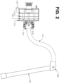
- a better illustration of the sensor 130 is provided by FIG. 2 and FIG. 3 , where FIG. 2 is a cross-sectional view of the probe 100 and FIG. 3 is a sectional view of the probe 100 where each portion of the probe 100 is shown as separated, prior to assembly.
- the sensor 130 is connected to the proximate portion 124 of the arm 120 by a collar 132.
- the collar 132 connects to both the proximate portion 124 of the arm 120 and to a housing 134 of the sensor 130. As is shown by FIG.
- the collar 132 may be connected to the arm 120 by a male/female connection having a first collar O-ring 138 there between so as to provide an airtight seal between the collar 132 and the arm 120, to prevent fluid immigration from inside of the tank.
- a male/female connection having a first collar O-ring 138 there between so as to provide an airtight seal between the collar 132 and the arm 120, to prevent fluid immigration from inside of the tank.
- other connection types between the collar 132 and the arm 120 may be used instead.
- the collar 132 is connected to the housing 134, thereby completing connection between the housing 134 and the arm 120.
- Connection between the collar 132 and the housing 134 may be provided via numerous methods, such as, but not limited to, use of a series of collar screws 142 and a second collar O-ring 144.
- the housing 134 does provide a cover for numerous objects.
- a series of printed circuit boards are located within the housing 134.
- a first PCB 150, a second PCB 170, and a third PCB 190 are located within the housing 134.
- the first PCB 150 is a power supply PCB.
- the first PCB 150 contains a power source, thereby providing power to the probe 100. Electrical components on the first PCB 150 are designed to prevent high-energy signals from propagation to the fluid.
- the second PCB 170 is a digital PCB having digital logic thereon, such as, but not limited to, a processor, such as, but not limited to, a digital signal processor (DSP) 172.
- DSP digital signal processor
- Functionality performed by the DSP 172 and other digital logic therein is described in detail below with reference to FIG. 4 and other figures. It should be noted that the present description refers to use of a DSP, but it should be noted that this is for exemplary purposes only, and that any processor may be supplemented.
- the third PCB 190 is an analog PCB having transmitter and receiver analog circuitry for allowing the probe 100 to transmit and receive signals. Functionality performed by the analog circuitry is described in detail below with reference to FIG. 5 .
- the first PCB 150, second PCB 170, and third PCB 190 are provided in a stacked arrangement with a series of stacking screws 146 maintaining the PCBs 150, 170, 190 in position within the housing 134.
- a cover 160 is also provided for sealing contents of the sensor 130 within the housing 134.
- a sensor connector 162 is partially located within the sensor housing 134. The sensor connector 162 provides an interface for connecting of the probe 100 to an aircraft interface.
- the power supply circuitry, transmitting and receiving logic, and digital logic may all be located on the same PCB, or on more or less than three PCBs.
- FIG. 4 is a schematic diagram further illustrating functionality and logic defined by the digital PCB 170.
- FIG. 5 is a schematic diagram further illustrating functionality and logic defined by the analog PCB 190. The following is a description of the sensor 130 specific to the second PCB 170 and the third PCB 190.
- FIG. 5 shows an example of basic implementation of the analog transmit and receive channels.
- a digital signal processor (DSP) 172 as shown by FIG. 4 , is provided to scan, track, and analyze associated data.
- a clock signal from the DSP 172 ( FIG. 4 ) is supplied to input A ( FIG. 5 ) and used to initiate a transmit pulse and to synchronize the receiver to the transmit pulse on the analog PCB 190.
- This signal activates the transmitter 192 to send an excitation pulse down the arm 120.
- the pulse travels down the elongated portion 110 all the way to the distal end of the elongated portion 112.
- the resulting reflection from the distal end 112 travels back and is captured by the receiver 194.
- This signal is filtered and buffered by a low frequency buffer 195 and sent to the DSP 172 to be converted to a digital signal and to be analyzed through output D.
- the same clock signal that is used to initiate the transmit pulse is also provided to the receiver 194.
- the clock signal is phase shifted (delayed) by a phase shifter 196 by an amount commanded by the DSP 172 ( FIG. 4 ) on input B.
- the receiver pulse is therefore delayed by the DSP 172 ( FIG. 4 ) and performs a spatial scan of the elongated portion 110 length.
- the actual amount of delay between the transmitter pulse and the receiver pulse is detected by a delay detector 198 and sent back as DC voltage to the DSP 172 via output C. This enables the DSP 172 to close the loop allowing the DSP 172 to have total control over the scanning function. Thus, specific discontinuities can be scanned or tracked at will.
- the transmitter 192 function is performed by elements transistor Q1, resistor R48, capacitor C5, and resistor R7.
- transistor Q1 acts as a switch to couple the energy stored in capacitor C5 onto the transmission line.
- Resistor R7 serves to decouple the transmitter 192 from the receiver 194.
- the receiver 194 function is performed by elements receiver R36, diode D2, capacitor C6, resistor R8, capacitor C7, transistor Q2, and resistor R55. Resistor R55 and resistor R8 provide a charging path for capacitor C6.
- Transistor Q2 serves as a switch to couple the energy stored in capacitor C6 onto resistor R8 thus turning on diode D2 via capacitor C7.
- Capacitor C7 in turn charges to and stores the voltage present at the transmission line, also referred to as sampling the transmission line.
- FIG. 4 shows the digital PCB 170.
- the DSP 172 sends a clock signal to activate transmitter 192 and receiver 194 through output A.
- the amount of delay is controlled by the DSP 172 via a digital to analog converter (DAC) 180 signal sent through output B to the analog PCB 190.
- DAC digital to analog converter
- the amount of delay between receiver 194 and transmitter 192 pulses is sensed by analog to digital converter ADC1 (175) via a voltage into input C and converted into a digital value to be read by the DSP 172.
- the DSP 172 uses this signal to determine delay between the transmitter 192 and the receiver 194 and adjusts delay control output for closed loop tracking purposes.
- Another analog signal fed back to the DSP 172 contains the reflection waveform from the elongated portion 110 of the probe (input D). This signal is fed into analog to digital converter ADC2 (174). From the converter, the signal is fed digitally into the DSP 172 for analysis.
- the signal amplitude from the receiver 194 may be adversely affected. This may lead to level detection inaccuracies.
- these effects are compensated for by increasing amplitude of the excitation pulse proportionally with the transmitter 192 output.
- the output signal at D ( FIG. 5 ), obtained during sampling of a known value, is fed into a low pass filter 193, an example of which is illustrated by FIG. 7 .
- the low pass filter 193 is located separate from the receiver 194 and transmitter 192, but still within the sensor 130.
- the resulting DC value is added to a pre-fixed bias, amplified, and added (or subtracted) to -Vee in FIG. 5 .
- -Vee we can vary the amplitude of the transmit pulse, hence compensating for the decrease (increase) of the signal at D due to the diode variation.
- the arm 120 of the probe 100 is filled with a dielectric having known impedance. Having the arm 120 of the probe 100 filled with a dielectric having a known impedance prevents the fluid that is being measured from entering into the arm 120 of the probe 100.
- the fluid were allowed to enter into the arm 120 of the probe, there would be discontinuities in the excitation signal transmitted from the sensor 130, to the arm 120, to the elongated portion 110 of the probe 100. Specifically, each time that the fluid is encountered by the excitation signal a discontinuity in the signal occurs. Therefore, it is beneficial to minimize discontinuity by ensuring that no fluid enters the arm 120 of the probe 100.
- minimizing discontinuity is performed by, for example, filling the arm 120 with a dielectric having a known impedance.
- the impedance of the dielectric is similar to an impedance of air or an impedance of the fluid for which a level is being determined.
- an excitation signal first travels from the sensor 130 to the top of the gauge-able section of the probe 100. If the impedance of the first transmission line section, namely, the arm 120 of the probe 100, is matched to that of a first media, such as the impedance of air, then there will not be an unwanted discontinuity between the first probe section and the second probe section, namely the elongated portion 110.
- a discontinuity at a boundary between media, such as between the air and the fluid for which a level is being determined, will cause a desired reflection of the excitation signal for processing by the sensor 130.
- this reflection will not create any undesired extra reflections at the impedance matched top and bottom of the probe 100.
- Part of the excitation signal travels further in the second media, namely, the fluid for which a level is being determined, to the distal end 112 of the elongated portion 110, which is in the fluid.
- Impedance of the third section of the transmission line is adjusted to match the value of the impedance of the second media, namely the impedance of the fluid.
- the impedance at the top of the probe 100 is matched to air, while the impedance at the bottom of the probe 100 is matched to the impedance of the fluid for which a level is being determined.
- the impedance matching may be performed by the sensor 130, by geometry of the probe 100, or by dielectric material adjustment.
- the excitation signal travels into the third section of the transmission line without any discontinuity to blur the level detection.
- the probe 100 it is desirable to have similar dielectric of the material used to fill the arm 120, the air, and the fluid.
- the similarities of the dielectrics results in less discontinuities in the excitation signal being transmitted from the sensor 130, through the arm 120 of the probe 100, into the elongated portion 110 of the probe 100, and into the fluid for which a level is being determined.
- the physical characteristics and functionality of the present probe 100 allow for the probe 100 to provide temperature measurement of fluid. This process is described in detail herein and performed by the DSP 172. Specifically, in processes where fluid level measurement is monitored, it is often desirable to know the fluid temperature as well. Knowing the fluid temperature may prove useful for process control or adjustments to fluid level readings itself to compensate for volume of fluid changed due to temperature.
- the present probe 100 alleviates the prior need for utilizing a separate, independent temperature sensor, and instead, integrates the properties of a temperature measurement sensor with the level measurement properties of the probe 100, resulting in a probe with less wiring and less intrusion into the process, and therefore, better reliability.
- the temperature of the fluid being measured can be deduced by measuring the actual dielectric constant of the fluid and comparing the measured actual dielectric constant to a chart having known dielectric constant values.
- a chart having known dielectric constant values For example, consider, for example, a hydrocarbon fluid.
- the propagation velocity of the signal in the fluid having a dielectric constant ⁇ 1 at certain temperature is shown by equation 1.
- V C ⁇ 1
- C speed of light.
- the fluid temperature changes its dielectric also changes to ⁇ 2 .
- Equation 2 The relationship between the propagation velocities may be represented by equation 2.
- V 1 V 2 E 2 E 1
- ⁇ 1 is the dielectric constant at, for example, 25°C
- ⁇ 2 is the dielectric constant at unknown temperature T. Equation 2 may be rewritten as equation 3 below.
- ⁇ 2 ⁇ 1 V 1 V 2 2 Knowing ⁇ 1 and V 1 , and by using a lookup table of ⁇ . values in various temperatures for this particular fluid, we find out the actual temperature T of the fluid.
- a pulse transmitted out into a transmission line will be partially or fully reflected back to the transmit port whenever the characteristic impedance of the transmission line changes.
- the characteristic impedance of a transmission line will change with the dielectric.
- Different transmission line geometries coax, parallel wire, etc. will have different relationships for characteristic impedance changes in different dielectrics. For a given transmission line geometry the dielectric changes in the transmission line will cause predictable changes in characteristic impedance.
- a level measuring system the probe 100, is designed to have a transmission line that passes thru different dielectrics.
- the transmission line will then have a very large impedance change at its end (open or short circuit). This very large impedance change in the transmission line will cause a very strong reflection at its end.
- a level measuring system could have a pulse travel in a transmission line that is placed in a medium of known dielectric. Part of the distance the pulse will travel will be in air (air dielectric) another part of the distance is traveled in a medium (medium dielectric).
- a velocity of propagation for each medium can be determined. We know the total distance traveled (length of transmission line).
- the distance traveled in the medium can be derived by use of equation 5 hereafter, which assumes that velocity in air is C.
- H D ⁇ C T / 1 ⁇ sqrt E m
- the probe 100 in order to provide fast fluid level scanning with reduced sensor processing time, the probe 100 is capable of tracking fluid level. Specifically, in the present fluid level measuring probe 100 very high speed reflecting waveforms need to be analyzed to determine positional changes in dielectric material caused by changes in fluid level.
- FIG. 6 is a flowchart 300 illustrating a method used by the probe 100 to scan and lock on a fluid level, in accordance with the first exemplary embodiment of the invention.
- the present probe 100 scans the entire length of the elongated portion 110 once via use of the excitation signal, to see where the fluid resides in the elongated portion 110 of the probe 100, also referred to as the current fluid level.
- One method of analyzing high-speed waveforms, such as the interrogation (excitation) signal provided by the sensor 130, is to use an aliasing sampling system to create a slower "equal time" waveform.
- the probe 100 can preserve the shape of the original very fast periodic waveform and render the waveform at a much slower rate. Sweeping a very narrow sampling point along a repeating waveform does this.
- the sampling window is delayed in time to sample the next fragment of the high-speed waveform. After many waveforms, the samples are combined by the sensor 130 into a slower representation of the original high-speed waveform which is suitable for processing by the DSP 172.
- the reflection of interest By analyzing the equal-time waveform, the reflection of interest can be located.
- the reflection of interest represents the current fluid level on the elongated portion (110) of probe 100.
- the fluid level is tracked by creating an equal-time representation of the high-speed waveform only in the vicinity of where the reflection of interest was located on previous cycles.
- the scan window timing is adjusted to keep the reflection of interest within the scan window.
- Using a metallic coaxial tube offers a unique advantage of low radio frequency emissions for the TDR device. This is extremely important for air borne application where the aircraft instrumentation is extremely sensitive to radiated noise. It also makes radio frequency reception by the TDR (susceptibility) less likely.
- An electrical spark can ignite the fluid in which the transmission line is immersed.
- shrouding the inner conductor of the elongated arm 110 by an outer metallic tube we prevent a spark between the inner conductor and the tank in which the fluid is held.
- electrically connecting the outer tube to the tank we prevent an electric potential difference between the tank and the elongated tube (110), thus, reducing the possibility of a spark.
- the amount of energy delivered into the measured fuel is limited by capacitor C5 ( FIG. 5 ).
- the capacitor prevents a direct current from flowing into the fuel.
- the only energy delivered is in a form of a pulse. This pulse has a limited energy dictated by the capacitance of C5.
- Another safety feature is the addition of voltage surge suppressors to the power supply that powers the probe 100 and communications inputs to the probe 100. These limit the amount of energy that can reach the fuel in case of a short circuit or over voltage transient..
Description
- This application claims priority to copending U.S. Provisional Application entitled, "TIME DOMAIN REFLECTROMETRY," having serial no.
60/976,615, filed October 1, 2007 - The present invention is generally related to fluid sensors, and more particularly is related to a fluid level sensor capable of compensating for multiple circumstances to provide an accurate fluid level reading.
- In many different fields there is a need to know a current level of fluid within a vessel. One method used to determine a current level of fluid within a vessel is the use of time domain reflectometry (TDR). As is known by those having ordinary skill in the art, TDR analysis includes the use of propagation of a step or pulse of energy having a sharp edge, also referred to as an interrogation, or excitation, signal, down a waveguide and into a system, and the subsequent observation of the energy reflected by the system. With the analyzing of the magnitude, duration, and shape of the reflected waveform, the nature of impedance variation in the transmission system can be determined.
- Unfortunately, maintaining an accurate measurement of fluid level is difficult. As previously mentioned, in a TDR system an interrogation signal is transmitted down a transmission line. A transmission line passing through different media will have regions of different dielectric. As a result, the reflected waveform will contain discontinuities at times that represent dielectric changes along the transmission line. In addition, traditional TDR systems continuously sweep the entire transmission line for a time span that corresponds to when a reflection of an originating signal is received, where the originating signal traveled from one end of the transmission line to the other. This process is repeated each time a new level indication is needed, which is a processing burden resulting in a costly system requiring excess power usage.
- Currently there is a need for an accurate, reliable, and safe method of measuring the amount of fluid in a container. An example of such a fluid may include, for example, a fuel tank containing volatile fluids. Thus, a heretofore unaddressed need exists in the industry to address the aforementioned deficiencies and inadequacies.
US 6,644,114 discloses an apparatus for precision tank level sensing, wherein a time-domain reflectometer (TDR) forms a pulse width modulated (PWM) signal directly on a transmission line, where the PWM width is proportional to range to a discontinuity on the transmission line. Two PWM detection methods can be used: (1) realtime, wherein the PWM signal is detected in realtime; and (2) expanded-time, wherein the PWM signal is time-expanded before detection for higher accuracy. Both methods convert the analog transmission-line PWM signal to a digital output PWM signal of identical duty-cycle for averaging, counting, or other processing to indicate range. In a preferred mode, a transmission line is sampled at a floating offset frequency relative to the transmission-line PWM frequency to form a PWM output having a floating time-expansion factor but a precise duty-cycle related to the location of the discontinuity. The essence of this TDR is low cost, precision and absolute simplicity. - In a first aspect, the present invention provides a system according to
claim 1. Briefly described, in architecture, one embodiment of the system, among others, can be implemented as follows. The system contains an elongated portion being a coaxial tube having a hollow center, an arm being coaxial in shape, and a sensor containing a transmitter capable of creating and transmitting an excitation electromagnetic pulse for traversing the elongated portion and the arm, and a receiver for receiving reflected pulses, wherein a proximate end of the elongated portion joins a distal end of the arm in a manner to create a waveguide for an electromagnetic pulse provided by the sensor. - The present system also provides for accurate measuring of fluid level in a vessel via use of an apparatus with a transmission line and a sensor, wherein the
sensor comprises a transmitter capable of creating and transmitting an excitation electromagnetic pulse for traversing the transmission line, and an aliasing sampling receiver for converting high speed reflected waveforms into a slower speed "equal time" waveform for processing by use of a method comprising the steps of: scanning a length of the transmission line that is placed partially or fully in fluid to see where the fluid resides along the transmission line, also referred to as the current fluid level; tracking the fluid level by identifying fluid level detection points within the slower speed "equal time" waveform output by a scan window of the aliasing sampling receiver; and adjusting the aliasing sampling receiver scan window to track on the detection points within the equal time representation of the pulse reflection, where the detection points in the reflection waveform represent position in the pulse reflection waveform representing a fluid level. - Other systems, methods, features, and advantages of the present invention will be or become apparent to one with skill in the art upon examination of the following drawings and detailed description. It is intended that all such additional systems, methods, features, and advantages be included within this description, be within the scope of the present invention, and be protected by the accompanying claims.
- Many aspects of the invention can be better understood with reference to the following drawings. The components in the drawings are not necessarily to scale, emphasis instead being placed upon clearly illustrating the principles of the present invention. Moreover, in the drawings, like reference numerals designate corresponding parts throughout the several views.
-
FIG. 1 is a schematic diagram illustrating the probe in accordance with a first exemplary embodiment of the invention -
FIG. 2 is a cross-sectional view of the probe ofFIG. 1 . -
FIG. 3 is a sectional view of the probe where each portion of the probe is shown as separated prior to assembly. -
FIG. 4 is a schematic diagram further illustrating functionality and logic defined by the digital PCB of the probe. -
FIG. 5 is a schematic diagram further illustrating functionality and logic defined by the analog PCB of the probe. -
FIG. 6 is a flowchart illustrating a method used by the probe to scan and lock on a fluid level, in accordance with the first exemplary embodiment of the invention. -
FIG. 7 is a schematic diagram illustrating an example of a low pass filter. - The present invention is a fluid level detection probe capable of accurately determining fluid levels in a vessel or container. For exemplary purposes, the present probe is described as a fuel level probe being capable of being positioned within a fuel tank. In such an example, the fuel level probe may be used to provide accurate measurement of gas or oil levels within a tank. It should be noted, however, that the type of fluid and the type of vessel is not intended to be limited by the present description.
-
FIG. 1 is a schematic diagram illustrating theprobe 100 in accordance with a first exemplary embodiment of the invention. As is shown byFIG. 1 , theprobe 100 contains anelongated portion 110, ashaped arm 120, and asensor 130. Theelongated portion 110 is a coaxial tube having a hollow center. Theelongated portion 110 is shaped and lengthened to allow for positioning within a fuel tank, wherein adistal end 112 of theelongated portion 110 extends toward a bottom of the fuel tank, in which theelongated portion 110 may be positioned. Having theelongated portion 110 hollow allows fluid to enter theelongated portion 110, via thedistal end 112, into the hollow portion to enable fluid level determination, as is explained in detail below. - A
proximate end 114 of theelongated portion 110 joins adistal end 122 of thearm 120. The connection between theelongated portion 110 and thearm 120 is provided in a manner so as to allow the combination of thearm 120 and theelongated portion 110 to create a waveguide for an electromagnetic pulse provided by thesensor 130. In addition, the combination of theelongated portion 110 and thearm 120 is coaxial in shape. WhileFIG. 1 illustrates aconnector 150 joining theelongated portion 110 and thearm 120, in accordance with an alternative embodiment of the invention, theprobe 100 may instead be fabricated to have theelongated portion 110 and thearm 120 as one piece. - The
elongated portion 110 and an outer shell of theshaped arm 120 are made of a conductive material having a known impedance, such as, for example, but not limited to, aluminum. It should be noted that other metals may be used as well. Thearm 120 is filled with a dielectric such as, but not limited to, Teflon. The Teflon fill is a solid dielectric. Use of a Teflon fill, in accordance with the present invention, serves at least two purposes. First, the Teflon fill provides impedance matching, as is described in more detail below, and second, the Teflon provides a means to prevent fluid ingression to a non-gauging portion of theprobe 100, thereby eliminating unwanted reflections due to multiple fluid levels inside of theprobe 100. - In accordance with the present invention, an electromagnetic excitation signal, also referred to herein as an interrogation signal, is sent by the
sensor 130 into a transmission line, wherein the transmission line includes the combination of thearm 120, theelongated portion 110, and beyond thedistal end 112 of theelongated portion 110. The transmission line has three sections. A first section of the transmission line is from an excitation source, such as thesensor 130, to a top of theprobe 100, also referred to as thedistal end 122 of the arm 120 (also referred to as the beginning of the gauge-able area). A second section of the transmission line is from the top of the probe 100 (thedistal end 122 of the arm 120) to a bottom of theprobe 100, also referred to as thedistal end 112 of theelongated portion 110. The second section of the transmission line is also referred to as the gauge-able area. A third section of the transmission line is from the bottom of theprobe 100 to the end of a transmission that runs past the end, ordistal portion 112, of the gauge-able area. The third section of the transmission line, optionally, is placed here to allow for impedance matching to the media being measured, as is described in additional detail below. - It should be noted that having the
probe 100 as coaxial in shape and partially filled with Teflon, or similar material, provides multiple advantages, such as, but not limited to, allowing for a constant impedance up to the gauging area and delimiting the gauging area. In addition, this allows theprobe 100 to be mounted horizontally below a fluid level, without multiple reflections from the fluid. Further, this configuration provides wet-to-dry side isolation. Still further, the configuration also provides mechanical means of attaching theelongated portion 110 to thesensor 130, thereby providing a more solid structure. - In accordance with the first exemplary embodiment of the invention, the
arm 120 of theprobe 100 is shaped like an "S." It should be noted that the shape of the arm may be different from the shape described herein. This presently disclosed shape is beneficial due to the contour of thearm 120 allowing theprobe 100 to rest on a lip of an entrance to a fuel tank, such as on the wing of an airplane, while theelongated portion 110 of theprobe 100 extends within the fuel tank and thesensor 130 remains outside of the fuel tank. It should be noted, however, that thearm 120 may be provided in other shapes so as to accommodate location of a fuel tank for which theprobe 100 is used. It should also be noted that the curved shape of thearm 120 allows for side mounting of theprobe 100 within a tank. - The
sensor 130 is connected to aproximate portion 124 of thearm 120. A better illustration of thesensor 130 is provided byFIG. 2 andFIG. 3 , whereFIG. 2 is a cross-sectional view of theprobe 100 andFIG. 3 is a sectional view of theprobe 100 where each portion of theprobe 100 is shown as separated, prior to assembly. In accordance with the present embodiment, thesensor 130 is connected to theproximate portion 124 of thearm 120 by acollar 132. Thecollar 132 connects to both theproximate portion 124 of thearm 120 and to ahousing 134 of thesensor 130. As is shown byFIG. 3 , thecollar 132 may be connected to thearm 120 by a male/female connection having a first collar O-ring 138 there between so as to provide an airtight seal between thecollar 132 and thearm 120, to prevent fluid immigration from inside of the tank. Of course, other connection types between thecollar 132 and thearm 120 may be used instead. - The
collar 132 is connected to thehousing 134, thereby completing connection between thehousing 134 and thearm 120. Connection between thecollar 132 and thehousing 134 may be provided via numerous methods, such as, but not limited to, use of a series of collar screws 142 and a second collar O-ring 144. - While the shape of the
housing 134 is not instrumental, thehousing 134 does provide a cover for numerous objects. As is shown byFIG. 2 andFIG. 3 , a series of printed circuit boards (PCBs) are located within thehousing 134. Specifically, afirst PCB 150, asecond PCB 170, and athird PCB 190 are located within thehousing 134. Thefirst PCB 150 is a power supply PCB. Thefirst PCB 150 contains a power source, thereby providing power to theprobe 100. Electrical components on thefirst PCB 150 are designed to prevent high-energy signals from propagation to the fluid. - The
second PCB 170 is a digital PCB having digital logic thereon, such as, but not limited to, a processor, such as, but not limited to, a digital signal processor (DSP) 172. Functionality performed by theDSP 172 and other digital logic therein is described in detail below with reference toFIG. 4 and other figures. It should be noted that the present description refers to use of a DSP, but it should be noted that this is for exemplary purposes only, and that any processor may be supplemented. - The
third PCB 190 is an analog PCB having transmitter and receiver analog circuitry for allowing theprobe 100 to transmit and receive signals. Functionality performed by the analog circuitry is described in detail below with reference toFIG. 5 . - The
first PCB 150,second PCB 170, andthird PCB 190 are provided in a stacked arrangement with a series of stackingscrews 146 maintaining thePCBs housing 134. Acover 160 is also provided for sealing contents of thesensor 130 within thehousing 134. It should be noted that asensor connector 162 is partially located within thesensor housing 134. Thesensor connector 162 provides an interface for connecting of theprobe 100 to an aircraft interface. - In accordance with an alternative embodiment of the invention, the power supply circuitry, transmitting and receiving logic, and digital logic may all be located on the same PCB, or on more or less than three PCBs.
- As mentioned above,
FIG. 4 is a schematic diagram further illustrating functionality and logic defined by thedigital PCB 170. In addition,FIG. 5 is a schematic diagram further illustrating functionality and logic defined by theanalog PCB 190. The following is a description of thesensor 130 specific to thesecond PCB 170 and thethird PCB 190. -
FIG. 5 shows an example of basic implementation of the analog transmit and receive channels. A digital signal processor (DSP) 172, as shown byFIG. 4 , is provided to scan, track, and analyze associated data. A clock signal from the DSP 172 (FIG. 4 ) is supplied to input A (FIG. 5 ) and used to initiate a transmit pulse and to synchronize the receiver to the transmit pulse on theanalog PCB 190. This signal activates thetransmitter 192 to send an excitation pulse down thearm 120. The pulse travels down theelongated portion 110 all the way to the distal end of theelongated portion 112. The resulting reflection from thedistal end 112 travels back and is captured by thereceiver 194. This signal is filtered and buffered by alow frequency buffer 195 and sent to theDSP 172 to be converted to a digital signal and to be analyzed through output D. - The same clock signal that is used to initiate the transmit pulse is also provided to the
receiver 194. At thereceiver 194, the clock signal is phase shifted (delayed) by aphase shifter 196 by an amount commanded by the DSP 172 (FIG. 4 ) on input B. The receiver pulse is therefore delayed by the DSP 172 (FIG. 4 ) and performs a spatial scan of theelongated portion 110 length. - The actual amount of delay between the transmitter pulse and the receiver pulse is detected by a
delay detector 198 and sent back as DC voltage to theDSP 172 via output C. This enables theDSP 172 to close the loop allowing theDSP 172 to have total control over the scanning function. Thus, specific discontinuities can be scanned or tracked at will. - The
transmitter 192 function is performed by elements transistor Q1, resistor R48, capacitor C5, and resistor R7. Here, transistor Q1 acts as a switch to couple the energy stored in capacitor C5 onto the transmission line. Resistor R7 serves to decouple thetransmitter 192 from thereceiver 194. Thereceiver 194 function is performed by elements receiver R36, diode D2, capacitor C6, resistor R8, capacitor C7, transistor Q2, and resistor R55. Resistor R55 and resistor R8 provide a charging path for capacitor C6. Transistor Q2 serves as a switch to couple the energy stored in capacitor C6 onto resistor R8 thus turning on diode D2 via capacitor C7. Capacitor C7 in turn charges to and stores the voltage present at the transmission line, also referred to as sampling the transmission line. -
FIG. 4 shows thedigital PCB 170. TheDSP 172 sends a clock signal to activatetransmitter 192 andreceiver 194 through output A. The amount of delay is controlled by theDSP 172 via a digital to analog converter (DAC) 180 signal sent through output B to theanalog PCB 190. - The amount of delay between
receiver 194 andtransmitter 192 pulses is sensed by analog to digital converter ADC1 (175) via a voltage into input C and converted into a digital value to be read by theDSP 172. TheDSP 172 uses this signal to determine delay between thetransmitter 192 and thereceiver 194 and adjusts delay control output for closed loop tracking purposes. - Another analog signal fed back to the
DSP 172 contains the reflection waveform from theelongated portion 110 of the probe (input D). This signal is fed into analog to digital converter ADC2 (174). From the converter, the signal is fed digitally into theDSP 172 for analysis. - It should be noted that, due to different environmental factors, the signal amplitude from the
receiver 194 may be adversely affected. This may lead to level detection inaccuracies. In accordance with an alternative embodiment of the invention, these effects are compensated for by increasing amplitude of the excitation pulse proportionally with thetransmitter 192 output. Specifically, the output signal at D (FIG. 5 ), obtained during sampling of a known value, is fed into alow pass filter 193, an example of which is illustrated byFIG. 7 . Preferably, thelow pass filter 193 is located separate from thereceiver 194 andtransmitter 192, but still within thesensor 130. The resulting DC value is added to a pre-fixed bias, amplified, and added (or subtracted) to -Vee inFIG. 5 . By varying -Vee, we can vary the amplitude of the transmit pulse, hence compensating for the decrease (increase) of the signal at D due to the diode variation. - As has been mentioned above, the
arm 120 of theprobe 100 is filled with a dielectric having known impedance. Having thearm 120 of theprobe 100 filled with a dielectric having a known impedance prevents the fluid that is being measured from entering into thearm 120 of theprobe 100. In the alternative, if the fluid were allowed to enter into thearm 120 of the probe, there would be discontinuities in the excitation signal transmitted from thesensor 130, to thearm 120, to theelongated portion 110 of theprobe 100. Specifically, each time that the fluid is encountered by the excitation signal a discontinuity in the signal occurs. Therefore, it is beneficial to minimize discontinuity by ensuring that no fluid enters thearm 120 of theprobe 100. In accordance with the present invention, minimizing discontinuity is performed by, for example, filling thearm 120 with a dielectric having a known impedance. In accordance with a preferred embodiment of the invention, the impedance of the dielectric is similar to an impedance of air or an impedance of the fluid for which a level is being determined. - In accordance with the
present probe 100 an excitation signal first travels from thesensor 130 to the top of the gauge-able section of theprobe 100. If the impedance of the first transmission line section, namely, thearm 120 of theprobe 100, is matched to that of a first media, such as the impedance of air, then there will not be an unwanted discontinuity between the first probe section and the second probe section, namely theelongated portion 110. - A discontinuity at a boundary between media, such as between the air and the fluid for which a level is being determined, will cause a desired reflection of the excitation signal for processing by the
sensor 130. By design, as mentioned above, this reflection will not create any undesired extra reflections at the impedance matched top and bottom of theprobe 100. Part of the excitation signal travels further in the second media, namely, the fluid for which a level is being determined, to thedistal end 112 of theelongated portion 110, which is in the fluid. - Impedance of the third section of the transmission line is adjusted to match the value of the impedance of the second media, namely the impedance of the fluid. In summary, the impedance at the top of the
probe 100 is matched to air, while the impedance at the bottom of theprobe 100 is matched to the impedance of the fluid for which a level is being determined. It should be noted that the impedance matching may be performed by thesensor 130, by geometry of theprobe 100, or by dielectric material adjustment. The excitation signal travels into the third section of the transmission line without any discontinuity to blur the level detection. - Therefore, in design of the
probe 100, it is desirable to have similar dielectric of the material used to fill thearm 120, the air, and the fluid. The similarities of the dielectrics results in less discontinuities in the excitation signal being transmitted from thesensor 130, through thearm 120 of theprobe 100, into theelongated portion 110 of theprobe 100, and into the fluid for which a level is being determined. - The physical characteristics and functionality of the
present probe 100 allow for theprobe 100 to provide temperature measurement of fluid. This process is described in detail herein and performed by theDSP 172. Specifically, in processes where fluid level measurement is monitored, it is often desirable to know the fluid temperature as well. Knowing the fluid temperature may prove useful for process control or adjustments to fluid level readings itself to compensate for volume of fluid changed due to temperature. Thepresent probe 100 alleviates the prior need for utilizing a separate, independent temperature sensor, and instead, integrates the properties of a temperature measurement sensor with the level measurement properties of theprobe 100, resulting in a probe with less wiring and less intrusion into the process, and therefore, better reliability. - By knowing the dielectric constants of the fluids (e.g., air and gas) in various temperatures, the temperature of the fluid being measured can be deduced by measuring the actual dielectric constant of the fluid and comparing the measured actual dielectric constant to a chart having known dielectric constant values. As an example, consider, for example, a hydrocarbon fluid. The propagation velocity of the signal in the fluid having a dielectric constant ε 1 at certain temperature is shown by
equation 1.
equation 1, C is speed of light.
As the fluid temperature changes, its dielectric also changes to ε 2. - The relationship between the propagation velocities may be represented by
equation 2.
equation 2, ε 1 is the dielectric constant at, for example, 25°C and ε 2 is the dielectric constant at unknowntemperature T. Equation 2 may be rewritten as equation 3 below.

- A pulse transmitted out into a transmission line will be partially or fully reflected back to the transmit port whenever the characteristic impedance of the transmission line changes. The characteristic impedance of a transmission line will change with the dielectric. Different transmission line geometries (coax, parallel wire, etc.) will have different relationships for characteristic impedance changes in different dielectrics. For a given transmission line geometry the dielectric changes in the transmission line will cause predictable changes in characteristic impedance.
- A level measuring system, the
probe 100, is designed to have a transmission line that passes thru different dielectrics. The transmission line will then have a very large impedance change at its end (open or short circuit). This very large impedance change in the transmission line will cause a very strong reflection at its end. - A level measuring system could have a pulse travel in a transmission line that is placed in a medium of known dielectric. Part of the distance the pulse will travel will be in air (air dielectric) another part of the distance is traveled in a medium (medium dielectric). Using Equation 1 a velocity of propagation for each medium can be determined. We know the total distance traveled (length of transmission line). By analyzing the reflected waveform the travel time from the beginning of the transmission line, thru both dielectrics, to the large impedance mismatch at the end of the transmission line can be measured. The distance traveled in the medium can be derived by use of equation 5 hereafter, which assumes that velocity in air is C.

- D = total distance of transmission thru both air and medium. This is the length or height, of the medium;
- C = speed of light;
- ε m = dielectric of medium;
- T = total time for a pulse or signal to travel thru both the air dielectric transmission line part and the medium dielectric part of the transmission line to the end of said transmission line;
- H = height of medium = the distance traveled in only medium dielectric part of the transmission line; and
- sqrt = square root.
- In accordance with the first exemplary embodiment of the invention, in order to provide fast fluid level scanning with reduced sensor processing time, the
probe 100 is capable of tracking fluid level. Specifically, in the present fluidlevel measuring probe 100 very high speed reflecting waveforms need to be analyzed to determine positional changes in dielectric material caused by changes in fluid level.FIG. 6 is aflowchart 300 illustrating a method used by theprobe 100 to scan and lock on a fluid level, in accordance with the first exemplary embodiment of the invention. - It should be noted that any process descriptions or blocks in flow charts should be understood as representing modules, segments, portions of code, or steps that include one or more instructions for implementing specific logical functions in the process, and alternative implementations are included within the scope of the present invention in which functions may be executed out of order from that shown or discussed, including substantially concurrently or in reverse order, depending on the functionality involved, as would be understood by those reasonably skilled in the art of the present invention.
- Instead of continuously scanning the entire length of the
elongated portion 110 for the level detection, as shown by block 302, thepresent probe 100 scans the entire length of theelongated portion 110 once via use of the excitation signal, to see where the fluid resides in theelongated portion 110 of theprobe 100, also referred to as the current fluid level. One method of analyzing high-speed waveforms, such as the interrogation (excitation) signal provided by thesensor 130, is to use an aliasing sampling system to create a slower "equal time" waveform. Theprobe 100 can preserve the shape of the original very fast periodic waveform and render the waveform at a much slower rate. Sweeping a very narrow sampling point along a repeating waveform does this. Each time the high-speed waveform is repeated, a single narrow sample of the waveform is taken by thesensor 130. At regular intervals, the sampling window is delayed in time to sample the next fragment of the high-speed waveform. After many waveforms, the samples are combined by thesensor 130 into a slower representation of the original high-speed waveform which is suitable for processing by theDSP 172. - By analyzing the equal-time waveform, the reflection of interest can be located. The reflection of interest represents the current fluid level on the elongated portion (110) of
probe 100. As shown by block 304, once the position of the current fluid level is determined, the fluid level is tracked by creating an equal-time representation of the high-speed waveform only in the vicinity of where the reflection of interest was located on previous cycles. As shown byblock 306, periodically, the scan window timing is adjusted to keep the reflection of interest within the scan window. - Scanning only where the fluid level can be expected and tracking the level greatly cuts required sensor processing time. Having a decreased sensor processing time allows a much faster system response rate for determining fluid level. This also results in a less costly system and less power consumption.
- Using a metallic coaxial tube (the combination of the
arm 120 and the elongated portion 110) offers a unique advantage of low radio frequency emissions for the TDR device. This is extremely important for air borne application where the aircraft instrumentation is extremely sensitive to radiated noise. It also makes radio frequency reception by the TDR (susceptibility) less likely. - It has an added benefit in case of flammable fluids immersion. An electrical spark can ignite the fluid in which the transmission line is immersed. By shrouding the inner conductor of the
elongated arm 110 by an outer metallic tube, we prevent a spark between the inner conductor and the tank in which the fluid is held. By electrically connecting the outer tube to the tank, we prevent an electric potential difference between the tank and the elongated tube (110), thus, reducing the possibility of a spark. - The amount of energy delivered into the measured fuel is limited by capacitor C5 (
FIG. 5 ). The capacitor prevents a direct current from flowing into the fuel. The only energy delivered is in a form of a pulse. This pulse has a limited energy dictated by the capacitance of C5. By keeping the capacitance low, we keep the amount of energy entering the fluid below a critical amount needed for ignition. - Another safety feature is the addition of voltage surge suppressors to the power supply that powers the
probe 100 and communications inputs to theprobe 100. These limit the amount of energy that can reach the fuel in case of a short circuit or over voltage transient..
Claims (14)
- A system for accurately measuring fluid level in a vessel, comprising:an elongated portion (110) being a coaxial waveguide having a first conductive outer shell that is hollow except for a coaxial inner conductor;an arm (120) being a coaxial waveguide comprising a second conductive outer shell, the arm being filled with a solid dielectric which yields a known impedance at conditions under which the fluid level is being measured; anda sensor (130) comprising a transmitter capable of creating and transmitting an excitation electromagnetic pulse for traversing the elongated portion and the arm, and a receiver for receiving reflected pulses, the sensor further comprising power supply circuitry, digital logic, and analog circuitry;wherein a proximate end (114) of the elongated portion (110) physically joins a distal end (122) of the arm (120) in a manner to create a continuous waveguide comprising the arm and the elongate portion for an electromagnetic pulse provided by the sensor; andwherein the digital logic further comprises a processor, wherein the processor further comprises:logic configured to initiate the transmitter for sending the excitation electromagnetic pulse;logic configured to synchronize the receiver to the excitation electromagnetic pulse; andlogic configured to determine temperature of the fluid by measuring actual dielectric constant of the fluid and comparing the measured actual dielectric constant of the fluid to a list of fluids having known dielectric constant values.
- The system of claim 1, wherein the elongated portion and an outer shell of the arm are made of a conductive material, geometry, and dielectric which yields a known impedance at conditions under which the fluid level is being measured.
- The system of claim 2, wherein the geometry and dielectric constant yield a known impedance that is similar to an impedance of air or an impedance of the fluid being measured at conditions under which the fluid level is being measured.
- The system of claim 1, wherein electrical components included within the power supply circuitry are designed to prevent high energy signals from propagating to the fluid being measured by the system.
- The system of claim 1, wherein the analog circuitry further comprises the transmitter and the receiver.
- The system of claim 1, wherein initiating of the transmitter for sending the excitation electromagnetic pulse is performed by a clock signal from the processor, wherein the same clock signal is sent to the receiver.
- The system of claim 1, wherein the processor further comprises logic configured to determine level of the fluid via use of time of flight of the excitation electromagnetic pulse to the end of the elongated portion.
- The system of claim 1, wherein the processor further comprises:logic configured to determine a current level of fluid; andlogic configured to track current fluid level by maintaining the current fluid level within a scan window, wherein timing of the scan window is adjusted to keep the current level of the fluid within the window.
- A system for accurately measuring fluid level in a vessel, comprising:an elongated portion (110) being a coaxial waveguide having a first conductive outer shell that is hollow except for a coaxial inner conductor;the elongated portion made of a material, geometry, and dielectric which yields a first known impedance at a top portion disposed in the air and a second known impedance at a bottom portion disposed in the fluid, at conditions under which the fluid level is being measured, wherein the impedance at the top portion is matched to air, while the impedance at the bottom portion is matched to the impedance of the fluid for which the fluid level is being determined;a fixed shaped coaxial arm (120) comprising a second conductive outer shell and wherein the outer shell is filled with Teflon;a sensor (130) comprising a transmitter capable of creating and transmitting an excitation electromagnetic pulse for traversing the elongated portion and the arm, and a receiver for receiving reflected pulses, the sensor further comprises power supply circuitry, digital logic, and analog circuitry;wherein a proximate end of the elongated portion physically joins a distal end of the arm in a manner to create a continuous waveguide comprising the arm and the elongated portion for an electromagnetic pulse provided by the sensor, and the arm is in the shape of an S; andwherein the digital logic further comprises a processor, wherein the processor further comprises:
logic configured to initiate the transmitter for sending the excitation electromagnetic pulse,logic configured to synchronize the receiver to the excitation electromagnetic pulse, andlogic configured to determine temperature of the fluid by measuring actual dielectric constant of the fluid and comparing the measured actual dielectric constant of the fluid to a list of fluids having known dielectric constant values. - A method of accurately measuring fluid level in a vessel, the method comprising:creating and transmitting an excitation electromagnetic pulse to traverse along a continuous waveguide comprising an elongated portion (110), being a coaxial waveguide having a first conductive outer shell that is hollow except for a coaxial inner conductor, and an arm (120), being a coaxial waveguide comprising a second conductive outer shell, the arm being filled with a solid dielectric which yields a known impedance at conditions under which the fluid level is being measured, and wherein a proximate end (114) of the elongated portion (110) physically joins a distal end (122) of the arm (120);receiving reflected pulses at a receiver;synchronizing the receiver to the excitation electromagnetic pulse; anddetermining a temperature of the fluid by measuring actual dielectric constant of the fluid and comparing the measured actual dielectric constant of the fluid to a list of fluids having known dielectric constant values.
- The method of claim 10, wherein the method is configured to determine the level of the fluid via use of time of flight of the excitation electromagnetic pulse to the end of the elongated portion.
- The method of claim 10, wherein the method is configured to:measure perceived length of the elongated portion immersed in the fluid; andcalculate the dielectric constant of the fluid from a ratio of the perceived length and a real length of the elongated portion having the fluid therein.
- The method of claim 10, wherein the method is configured to:determine a current level of fluid; andtrack current fluid level by maintaining the current fluid level within a scan window, wherein timing of the scan window is adjusted to keep the current level of the fluid within the window.
- The method of claim 10, wherein the method comprises the steps of:scanning a length of the transmission line that is placed partially or fully in fluid to see where the fluid resides along the transmission line, also referred to as the current fluid level;using an aliasing sampling receiver for converting high speed reflected waveforms into a slower speed "equal time" waveform;tracking the fluid level by identifying fluid level detection points within the slower speed "equal time" waveform output by a scan window of the aliasing sampling receiver; andadjusting the aliasing sampling receiver scan window to track on the detection points within the equal time representation of the pulse reflection,where the detection points in the reflection waveform represent position in the pulse reflection waveform representing a fluid level.
Applications Claiming Priority (2)
| Application Number | Priority Date | Filing Date | Title |
|---|---|---|---|
| US97661507P | 2007-10-01 | 2007-10-01 | |
| PCT/US2008/078444 WO2009046103A1 (en) | 2007-10-01 | 2008-10-01 | System and method for accurately measuring fluid level in a vessel |
Publications (3)
| Publication Number | Publication Date |
|---|---|
| EP2198252A1 EP2198252A1 (en) | 2010-06-23 |
| EP2198252A4 EP2198252A4 (en) | 2015-08-12 |
| EP2198252B1 true EP2198252B1 (en) | 2023-06-21 |
Family
ID=40526646
Family Applications (1)
| Application Number | Title | Priority Date | Filing Date |
|---|---|---|---|
| EP08835729.8A Active EP2198252B1 (en) | 2007-10-01 | 2008-10-01 | System and method for accurately measuring fluid level in a vessel |
Country Status (9)
| Country | Link |
|---|---|
| US (3) | US9453755B2 (en) |
| EP (1) | EP2198252B1 (en) |
| JP (1) | JP2010540942A (en) |
| CN (1) | CN101836091A (en) |
| BR (1) | BRPI0817500B8 (en) |
| CA (1) | CA2701375C (en) |
| GB (2) | GB2492691B8 (en) |
| RU (1) | RU2482453C2 (en) |
| WO (1) | WO2009046103A1 (en) |
Families Citing this family (24)
| Publication number | Priority date | Publication date | Assignee | Title |
|---|---|---|---|---|
| US8746045B2 (en) | 2006-11-17 | 2014-06-10 | Meggitt (Orange County), Inc. | System and method for identifying fluids and monitoring fluid quality in a vessel |
| US7650785B1 (en) | 2006-11-17 | 2010-01-26 | Vibro-Meter, Inc. | Scan lock and track fluid characterization and level sensor apparatus and method |
| US8794063B2 (en) | 2007-01-08 | 2014-08-05 | Meggitt (Orange County), Inc. | System and method for optimizing sweep delay and aliasing for time domain reflectometric measurement of liquid height within a tank |
| JP2010540942A (en) | 2007-10-01 | 2010-12-24 | バイブロ−メーター インコーポレイテッド | System and method for accurately measuring fluid level in a container |
| US8549909B2 (en) | 2007-10-01 | 2013-10-08 | Meggitt (Orange County), Inc. | Vessel probe connector with solid dielectric therein |
| US20100148643A1 (en) * | 2008-12-16 | 2010-06-17 | K-Tek Corp. | Housing for Sensor Interface Electronics |
| CA2734001C (en) | 2010-03-14 | 2016-01-19 | Titan Logix Corp. | System and method for measuring and metering deicing fluid from a tank using a refractometer module |
| WO2012102701A1 (en) | 2011-01-25 | 2012-08-02 | Hewlett-Packard Development Company, L.P. | Capacitive fluid level sensing |
| DE112013004129T5 (en) * | 2012-08-22 | 2015-05-21 | General Electric Company | Wireless system and method for measuring an operating condition of a machine |
| GB201220658D0 (en) * | 2012-11-16 | 2013-01-02 | Airbus Operations Ltd | Time domain reflectometry fuel gauge |
| US9488514B2 (en) * | 2013-01-15 | 2016-11-08 | Ssi Technologies, Inc. | Three-mode sensor for determining temperature, level, and concentration of a fluid |
| TWI476378B (en) * | 2013-11-12 | 2015-03-11 | Finetek Co Ltd | Level and temperature sensing device |
| TWI486560B (en) * | 2013-11-25 | 2015-06-01 | Finetek Co Ltd | Cable level temperature sensor |
| DE102014114752A1 (en) * | 2014-10-10 | 2016-04-14 | Krohne S. A. S. | Method and device for level measurement |
| EP3302248A4 (en) | 2015-06-01 | 2019-01-30 | Digital Hospital, Inc. | Dosage confirmation apparatus |
| US9711838B2 (en) * | 2015-10-29 | 2017-07-18 | Honeywell International Inc. | Indexed centering spacer for coaxial probes in guided wave radar level transmitters |
| US10379131B2 (en) | 2015-11-18 | 2019-08-13 | Elbit Systems Of America/Kmc Systems, Inc. | Systems and methods for detecting a liquid level |
| US9702750B1 (en) * | 2016-01-12 | 2017-07-11 | Finetek Co., Ltd. | Material level indicator |
| US10326980B2 (en) * | 2016-02-04 | 2019-06-18 | Simmonds Precision Products, Inc. | Imaging system for fuel tank analysis |
| US10424076B2 (en) | 2016-02-04 | 2019-09-24 | Simmonds Precision Products, Inc. | Imaging system for fuel tank analysis |
| JP6096971B1 (en) * | 2016-08-25 | 2017-03-15 | ムサシノ機器株式会社 | High liquid level alarm device |
| EP3473988B1 (en) * | 2017-10-17 | 2020-04-29 | VEGA Grieshaber KG | Fill level measuring assembly with flexible hose type transmission and receiving waveguides |
| DE102017126734A1 (en) * | 2017-11-14 | 2019-05-16 | Endress+Hauser SE+Co. KG | Method of creating a blanking curve for a level gauge |
| US11555731B2 (en) * | 2017-11-14 | 2023-01-17 | Rochester Sensors, Llc | TDR transducer with boomerang waveguide |
Family Cites Families (76)
| Publication number | Priority date | Publication date | Assignee | Title |
|---|---|---|---|---|
| US3246180A (en) | 1962-02-14 | 1966-04-12 | Socony Mobil Oil Co Inc | Control system for controlling the flow of fluids |
| US3474337A (en) * | 1966-12-27 | 1969-10-21 | Jackson & Church Electronics C | System for sensing levels and electrical characteristics of fluent materials |
| US3874237A (en) * | 1973-02-15 | 1975-04-01 | Canadian Patents Dev | Liquid level height measuring apparatus |
| US4161704A (en) * | 1977-01-21 | 1979-07-17 | Uniform Tubes, Inc. | Coaxial cable and method of making the same |
| CA1169943A (en) | 1980-06-13 | 1984-06-26 | John B. Cole | Method and apparatus for measuring the position of an interface between different materials by frequency domain reflectometry |
| CA1214858A (en) * | 1984-09-27 | 1986-12-02 | Stanley Panton | Acoustic ranging system |
| US4786857A (en) * | 1986-04-24 | 1988-11-22 | Charles L. Mohr | Methods and apparatus for time domain reflectometry determination of relative proportion, fluid inventory and turbulence |
| US4881912A (en) | 1988-04-29 | 1989-11-21 | Specialty Connector Company, Inc. | High voltage coaxial connector |
| US5160933A (en) | 1990-08-28 | 1992-11-03 | Honeywell Inc. | Radar altimeter with self-calibration feature |
| US5457990A (en) * | 1991-12-03 | 1995-10-17 | Cambridge Consultants Limited | Method and apparatus for determining a fluid level in the vicinity of a transmission line |
| GB9211086D0 (en) * | 1992-05-23 | 1992-07-15 | Cambridge Consultants | Short range electromagnetic sensing signal processing |
| US6138508A (en) * | 1993-10-27 | 2000-10-31 | Kdi Precision Products, Inc. | Digital liquid level sensing apparatus |
| DE4405238C2 (en) | 1994-02-18 | 1998-07-09 | Endress Hauser Gmbh Co | Arrangement for measuring the level in a container |
| US20050192727A1 (en) * | 1994-05-09 | 2005-09-01 | Automotive Technologies International Inc. | Sensor Assemblies |
| US5610611A (en) * | 1994-12-19 | 1997-03-11 | The Regents Of The University Of California | High accuracy electronic material level sensor |
| US5609059A (en) | 1994-12-19 | 1997-03-11 | The Regents Of The University Of California | Electronic multi-purpose material level sensor |
| US5765433A (en) | 1995-03-10 | 1998-06-16 | Arizona Instrument Corporation | Liquid measuring system and methods |
| US5827985A (en) * | 1995-12-19 | 1998-10-27 | Endress + Hauser Gmbh + Co. | Sensor apparatus for process measurement |
| US5841666A (en) * | 1995-12-21 | 1998-11-24 | Endress + Hauser Gmbh + Co. | Processor apparatus and method for a process measurement signal |
| US6285538B1 (en) | 1996-02-20 | 2001-09-04 | General Electric Company | Partial discharge coupler |
| US6122602A (en) * | 1997-05-02 | 2000-09-19 | Endress + Hauser Gmbh + Co. | Method and arrangement for electromagnetic wave distance measurement by the pulse transit time method |
| US6281801B1 (en) * | 1997-06-04 | 2001-08-28 | Bechtel Bwxt Idaho, Llc | System and method for monitoring water content or other dielectric influences in a medium |
| US5943908A (en) * | 1997-09-08 | 1999-08-31 | Teleflex Incorporated | Probe for sensing fluid level |
| US5943003A (en) | 1997-11-18 | 1999-08-24 | Raytheon Company | Radar system |
| US5973637A (en) * | 1998-01-09 | 1999-10-26 | Endress + Hauser Gmbh + Co. | Partial probe mapping |
| US6078280A (en) | 1998-01-09 | 2000-06-20 | Endress + Hauser Gmbh + Co. | Periodic probe mapping |
| US6069581A (en) * | 1998-02-20 | 2000-05-30 | Amerigon | High performance vehicle radar system |
| US6626038B1 (en) * | 1998-06-18 | 2003-09-30 | Magnetrol International Inc. | Time domain reflectometry measurement instrument |
| US6229476B1 (en) | 1998-11-27 | 2001-05-08 | Endress+ Hauser Gmbh+ Co. | Liquid level meter |
| US6559657B1 (en) * | 1999-01-13 | 2003-05-06 | Endress+Hauser Gmbh+Co. | Probe mapping diagnostic methods |
| JP3679651B2 (en) | 1999-07-30 | 2005-08-03 | ヒロセ電機株式会社 | L-type coaxial connector |
| US6297969B1 (en) * | 1999-08-10 | 2001-10-02 | Lucent Technologies Inc. | Electromagnetic interference shielding enclosure |
| US6644114B1 (en) * | 1999-12-30 | 2003-11-11 | Mcewan Technologies, Llc | Direct PWM reflectometer |
| GB0004306D0 (en) | 2000-02-23 | 2000-04-12 | Cambridge Consultants | Time domain reflectometry |
| AU2001249105A1 (en) * | 2000-03-07 | 2001-09-17 | Honeywell International, Inc. | Apparatus and method for measuring the level of a fluid |
| US6690320B2 (en) * | 2000-06-13 | 2004-02-10 | Magnetrol International Incorporated | Time domain reflectometry measurement instrument |
| US6504793B2 (en) * | 2000-09-11 | 2003-01-07 | Vega Grieshaber Kg | Method and device for range measurement |
| US6701783B2 (en) * | 2000-09-12 | 2004-03-09 | Vega Grieshaber Kg | Device and a process for determining the positions of border areas between different mediums |
| NL1016247C2 (en) | 2000-09-22 | 2002-03-25 | Martil Instr B V | Heart-lung machine provided with an electrical impedance measurement device for signaling microemboli and / or fibrinogen concentration. |
| EP1209451A1 (en) | 2000-11-13 | 2002-05-29 | Krohne S.A. | Level measuring device |
| US6650280B2 (en) * | 2000-12-08 | 2003-11-18 | The United States Of America As Represented By The Administrator Of The National Aeronautics And Space Administration | Measurement system and method |
| JP2002231394A (en) | 2001-01-30 | 2002-08-16 | Auto Network Gijutsu Kenkyusho:Kk | Shielding connector and its manufacturing method |
| RU2193164C1 (en) | 2001-10-05 | 2002-11-20 | Балин Николай Иванович | Liquid level measuring device (versions) |
| US6556511B1 (en) * | 2001-11-01 | 2003-04-29 | Techno Research | Method of locking onto and tracking a target |
| DE10160688A1 (en) * | 2001-12-11 | 2003-06-18 | Endress & Hauser Gmbh & Co Kg | Device for determining and / or monitoring the level of a product in a container |
| CA2384257A1 (en) * | 2002-04-29 | 2003-10-29 | Siemens Milltronics Process Instruments Inc. | Time domain reflectometry probe for level sensing |
| DE10220478A1 (en) | 2002-05-07 | 2003-11-27 | Framatome Anp Gmbh | Electrical implementation and use of the electrical implementation |
| DE10220479A1 (en) | 2002-05-07 | 2003-11-27 | Framatome Anp Gmbh | Method for determining a characteristic position value for an interface of a medium held in a container |
| US6993967B2 (en) * | 2002-07-12 | 2006-02-07 | Ti Group Automotive Systems, L.L.C. | Fluid level sensor |
| WO2004017025A1 (en) | 2002-08-13 | 2004-02-26 | Vega Grieshaber Kg | System for the production of a modular structure for the determination of a physical process variable and standardised components |
| US6801157B2 (en) | 2002-10-02 | 2004-10-05 | Magnetrol International, Inc. | Guided wave radar level transmitter |
| US7068051B2 (en) * | 2003-02-19 | 2006-06-27 | Technical Development Consultants, Inc. | Permittivity monitor uses ultra wide band transmission |
| DE60325786D1 (en) | 2003-09-15 | 2009-02-26 | Corning Cabelcon As | COAXIALWINKEL CONNECTOR |
| DE602004014631D1 (en) * | 2003-10-15 | 2008-08-07 | Axsensor Ab | MEASURING DEVICE FOR FLUID LEVEL |
| RU2249796C1 (en) | 2003-11-10 | 2005-04-10 | Гусев Александр Леонидович | Method and device for measuring cryogenic liquid level in vessel |
| JP3784813B2 (en) | 2003-11-26 | 2006-06-14 | 本田技研工業株式会社 | High-voltage cooling device for vehicle motor and hybrid vehicle |
| US6988404B2 (en) | 2003-12-11 | 2006-01-24 | Ohmart/Vega Corporation | Apparatus for use in measuring fluid levels |
| CN100445703C (en) * | 2003-12-23 | 2008-12-24 | 茵爱莎公司 | Non-invasive method for detecting and measuring filling material in vessels |
| US7165450B2 (en) * | 2004-07-01 | 2007-01-23 | Mohammad Ali Jamnia | Variable position sensor employing magnetic flux and housing therefore |
| DE102004032965B4 (en) | 2004-07-07 | 2015-03-05 | Endress + Hauser Gmbh + Co. Kg | Device for aligning and centering a rod-shaped or rope-shaped surface waveguide of a field device |
| US7334470B1 (en) | 2004-09-30 | 2008-02-26 | Siemens Milltronics Process Instruments, Inc. | Digital interface and receiver for time-of-flight level measurement and pulse-echo ranging systems |
| US7255002B2 (en) * | 2005-04-07 | 2007-08-14 | Rosemount, Inc. | Tank seal for guided wave radar level measurement |
| RU2289795C1 (en) | 2005-06-09 | 2006-12-20 | Валерий Александрович Кабатчиков | Level meter |
| US7489745B2 (en) * | 2005-10-11 | 2009-02-10 | L-3 Communications Integrated Systems L.P. | Reconfigurable direct RF bandpass sampling receiver and related methods |
| DE102006003742A1 (en) | 2006-01-25 | 2007-08-02 | Endress + Hauser Gmbh + Co. Kg | Device for determining and monitoring filling level of medium in tank, has dielectric filling body that comprises hermetically sealed recess volume in its inerior one, and antenna with antenna coupling-in region is also provided |
| US7446695B2 (en) | 2006-08-22 | 2008-11-04 | Mcewan Thomas Edward | Precision pulse detection system for radar sensors |
| US7823446B2 (en) | 2006-11-06 | 2010-11-02 | Rosemount Tank Radar Ab | Pulsed radar level gauging with relative phase detection |
| US8794063B2 (en) | 2007-01-08 | 2014-08-05 | Meggitt (Orange County), Inc. | System and method for optimizing sweep delay and aliasing for time domain reflectometric measurement of liquid height within a tank |
| DE102007030847A1 (en) * | 2007-07-03 | 2009-01-15 | Sick Ag | Sensor according to the TDR principle with a coaxial probe and manufacturing process for it |
| US7660494B2 (en) | 2007-08-13 | 2010-02-09 | The Boeing Company | Fiber optic fuel detection system |
| JP2010540942A (en) | 2007-10-01 | 2010-12-24 | バイブロ−メーター インコーポレイテッド | System and method for accurately measuring fluid level in a container |
| US8549909B2 (en) | 2007-10-01 | 2013-10-08 | Meggitt (Orange County), Inc. | Vessel probe connector with solid dielectric therein |
| US7525476B1 (en) | 2007-11-13 | 2009-04-28 | Rosemount Tank Radar Ab | System and method for filling level determination |
| DE102007060579B4 (en) | 2007-12-13 | 2019-04-25 | Endress+Hauser SE+Co. KG | Method for determining and / or assessing the filling state of a container filled with at least one medium |
| US7918133B2 (en) * | 2008-04-04 | 2011-04-05 | Ez Form Cable Corporation | Liquid level sensing apparatus |
| US8224594B2 (en) | 2008-09-18 | 2012-07-17 | Enraf B.V. | Apparatus and method for dynamic peak detection, identification, and tracking in level gauging applications |
-
2008
- 2008-10-01 JP JP2010527253A patent/JP2010540942A/en active Pending
- 2008-10-01 CA CA2701375A patent/CA2701375C/en active Active
- 2008-10-01 RU RU2010117162/28A patent/RU2482453C2/en active
- 2008-10-01 BR BRPI0817500A patent/BRPI0817500B8/en active IP Right Grant
- 2008-10-01 GB GB201218131A patent/GB2492691B8/en active Active
- 2008-10-01 CN CN200880112699A patent/CN101836091A/en active Pending
- 2008-10-01 US US12/243,511 patent/US9453755B2/en active Active
- 2008-10-01 EP EP08835729.8A patent/EP2198252B1/en active Active
- 2008-10-01 WO PCT/US2008/078444 patent/WO2009046103A1/en active Application Filing
- 2008-10-01 GB GB1006147.1A patent/GB2466162B/en active Active
-
2010
- 2010-10-08 US US12/901,463 patent/US8393208B2/en active Active
-
2011
- 2011-05-23 US US13/113,526 patent/US20110282599A1/en not_active Abandoned
Also Published As
| Publication number | Publication date |
|---|---|
| US20110282599A1 (en) | 2011-11-17 |
| RU2010117162A (en) | 2011-11-10 |
| GB2466162A (en) | 2010-06-16 |
| BRPI0817500B8 (en) | 2020-07-07 |
| BRPI0817500A2 (en) | 2015-07-14 |
| US20090235737A1 (en) | 2009-09-24 |
| GB201218131D0 (en) | 2012-11-21 |
| RU2482453C2 (en) | 2013-05-20 |
| JP2010540942A (en) | 2010-12-24 |
| WO2009046103A1 (en) | 2009-04-09 |
| EP2198252A1 (en) | 2010-06-23 |
| US20110209543A1 (en) | 2011-09-01 |
| GB2492691B (en) | 2013-02-20 |
| GB201006147D0 (en) | 2010-05-26 |
| GB2492691A (en) | 2013-01-09 |
| US8393208B2 (en) | 2013-03-12 |
| BRPI0817500B1 (en) | 2019-02-26 |
| GB2492691B8 (en) | 2013-02-27 |
| CA2701375A1 (en) | 2009-04-09 |
| US9453755B2 (en) | 2016-09-27 |
| CN101836091A (en) | 2010-09-15 |
| CA2701375C (en) | 2015-11-24 |
| GB2466162B (en) | 2012-12-05 |
| EP2198252A4 (en) | 2015-08-12 |
| GB2492691A8 (en) | 2013-02-27 |
Similar Documents
| Publication | Publication Date | Title |
|---|---|---|
| EP2198252B1 (en) | System and method for accurately measuring fluid level in a vessel | |
| US5457990A (en) | Method and apparatus for determining a fluid level in the vicinity of a transmission line | |
| US5656774A (en) | Apparatus and method for sensing fluid level | |
| US9069056B2 (en) | Guided wave radar probe reference target | |
| US6690320B2 (en) | Time domain reflectometry measurement instrument | |
| US9217659B2 (en) | Guided wave radar probe with leak detection | |
| US6867729B2 (en) | Guided wave radar level transmitter with automatic velocity compensation | |
| US7525476B1 (en) | System and method for filling level determination | |
| JP3860802B2 (en) | Electronic multipurpose substance level sensor | |
| US7965087B2 (en) | Method for ascertaining and monitoring fill level of a medium in a container | |
| US6477474B2 (en) | Measurement of process product dielectric constant using a low power radar level transmitter | |
| US5847567A (en) | Microwave level gauge with remote transducer | |
| EP2490040B1 (en) | Single conductor probe gwr system with reduced end of nozzle reflection | |
| US6906662B2 (en) | Time domain reflectometry measurement instrument | |
| US9279705B2 (en) | High temperature high pressure seal | |
| JPH09288069A (en) | Method and apparatus for processing time domain reflection measuring signal | |
| EP3301412A1 (en) | Guided wave radar level gauge system with dual transmission line probes for dielectric constant compensation | |
| EP1923677A2 (en) | Method and apparatus for carrying out time domain reflectometry | |
| EP2728318B1 (en) | Diode switched front end for guided wave radar level transmitter | |
| CA2880952C (en) | System and method for accurately measuring fluid level in a vessel | |
| US11933655B2 (en) | Radar level gauge system and method for reduced lower dead zone | |
| WO2002063249A2 (en) | Material level sensing system and method |
Legal Events
| Date | Code | Title | Description |
|---|---|---|---|
| PUAI | Public reference made under article 153(3) epc to a published international application that has entered the european phase |
Free format text: ORIGINAL CODE: 0009012 |
|
| 17P | Request for examination filed |
Effective date: 20100419 |
|
| AK | Designated contracting states |
Kind code of ref document: A1 Designated state(s): AT BE BG CH CY CZ DE DK EE ES FI FR GB GR HR HU IE IS IT LI LT LU LV MC MT NL NO PL PT RO SE SI SK TR |
|
| AX | Request for extension of the european patent |
Extension state: AL BA MK RS |
|
| RIN1 | Information on inventor provided before grant (corrected) |
Inventor name: RIZZO, VINCENT Inventor name: CARVALHO, CARLOS Inventor name: MISKELL, THOMAS Inventor name: LAVON, RONIE |
|
| DAX | Request for extension of the european patent (deleted) | ||
| RAP1 | Party data changed (applicant data changed or rights of an application transferred) |
Owner name: MEGGITT (NEW HAMPSHIRE), INC. |
|
| RAP1 | Party data changed (applicant data changed or rights of an application transferred) |
Owner name: MEGGITT (ORANGE COUNTY), INC. |
|
| RA4 | Supplementary search report drawn up and despatched (corrected) |
Effective date: 20150713 |
|
| RIC1 | Information provided on ipc code assigned before grant |
Ipc: G01F 23/284 20060101AFI20150707BHEP |
|
| STAA | Information on the status of an ep patent application or granted ep patent |
Free format text: STATUS: EXAMINATION IS IN PROGRESS |
|
| 17Q | First examination report despatched |
Effective date: 20190521 |
|
| STAA | Information on the status of an ep patent application or granted ep patent |
Free format text: STATUS: EXAMINATION IS IN PROGRESS |
|
| STAA | Information on the status of an ep patent application or granted ep patent |
Free format text: STATUS: EXAMINATION IS IN PROGRESS |
|
| GRAP | Despatch of communication of intention to grant a patent |
Free format text: ORIGINAL CODE: EPIDOSNIGR1 |
|
| STAA | Information on the status of an ep patent application or granted ep patent |
Free format text: STATUS: GRANT OF PATENT IS INTENDED |
|
| INTG | Intention to grant announced |
Effective date: 20230103 |
|
| RIN1 | Information on inventor provided before grant (corrected) |
Inventor name: RIZZO, VINCENT Inventor name: MISKELL, THOMAS Inventor name: CARVALHO, CARLOS Inventor name: LAVON, RONIE |
|
| GRAS | Grant fee paid |
Free format text: ORIGINAL CODE: EPIDOSNIGR3 |
|
| GRAA | (expected) grant |
Free format text: ORIGINAL CODE: 0009210 |
|
| STAA | Information on the status of an ep patent application or granted ep patent |
Free format text: STATUS: THE PATENT HAS BEEN GRANTED |
|
| AK | Designated contracting states |
Kind code of ref document: B1 Designated state(s): AT BE BG CH CY CZ DE DK EE ES FI FR GB GR HR HU IE IS IT LI LT LU LV MC MT NL NO PL PT RO SE SI SK TR |
|
| REG | Reference to a national code |
Ref country code: GB Ref legal event code: FG4D |
|
| REG | Reference to a national code |
Ref country code: CH Ref legal event code: EP |
|
| REG | Reference to a national code |
Ref country code: DE Ref legal event code: R096 Ref document number: 602008064790 Country of ref document: DE |
|
| REG | Reference to a national code |
Ref country code: AT Ref legal event code: REF Ref document number: 1581197 Country of ref document: AT Kind code of ref document: T Effective date: 20230715 |
|
| REG | Reference to a national code |
Ref country code: IE Ref legal event code: FG4D |
|
| REG | Reference to a national code |
Ref country code: LT Ref legal event code: MG9D |
|
| REG | Reference to a national code |
Ref country code: NL Ref legal event code: MP Effective date: 20230621 |
|
| PG25 | Lapsed in a contracting state [announced via postgrant information from national office to epo] |
Ref country code: SE Free format text: LAPSE BECAUSE OF FAILURE TO SUBMIT A TRANSLATION OF THE DESCRIPTION OR TO PAY THE FEE WITHIN THE PRESCRIBED TIME-LIMIT Effective date: 20230621 Ref country code: NO Free format text: LAPSE BECAUSE OF FAILURE TO SUBMIT A TRANSLATION OF THE DESCRIPTION OR TO PAY THE FEE WITHIN THE PRESCRIBED TIME-LIMIT Effective date: 20230921 |
|
| REG | Reference to a national code |
Ref country code: AT Ref legal event code: MK05 Ref document number: 1581197 Country of ref document: AT Kind code of ref document: T Effective date: 20230621 |
|
| PG25 | Lapsed in a contracting state [announced via postgrant information from national office to epo] |
Ref country code: NL Free format text: LAPSE BECAUSE OF FAILURE TO SUBMIT A TRANSLATION OF THE DESCRIPTION OR TO PAY THE FEE WITHIN THE PRESCRIBED TIME-LIMIT Effective date: 20230621 Ref country code: LV Free format text: LAPSE BECAUSE OF FAILURE TO SUBMIT A TRANSLATION OF THE DESCRIPTION OR TO PAY THE FEE WITHIN THE PRESCRIBED TIME-LIMIT Effective date: 20230621 Ref country code: LT Free format text: LAPSE BECAUSE OF FAILURE TO SUBMIT A TRANSLATION OF THE DESCRIPTION OR TO PAY THE FEE WITHIN THE PRESCRIBED TIME-LIMIT Effective date: 20230621 Ref country code: HR Free format text: LAPSE BECAUSE OF FAILURE TO SUBMIT A TRANSLATION OF THE DESCRIPTION OR TO PAY THE FEE WITHIN THE PRESCRIBED TIME-LIMIT Effective date: 20230621 Ref country code: GR Free format text: LAPSE BECAUSE OF FAILURE TO SUBMIT A TRANSLATION OF THE DESCRIPTION OR TO PAY THE FEE WITHIN THE PRESCRIBED TIME-LIMIT Effective date: 20230922 |
|
| PG25 | Lapsed in a contracting state [announced via postgrant information from national office to epo] |
Ref country code: FI Free format text: LAPSE BECAUSE OF FAILURE TO SUBMIT A TRANSLATION OF THE DESCRIPTION OR TO PAY THE FEE WITHIN THE PRESCRIBED TIME-LIMIT Effective date: 20230621 |
|
| PG25 | Lapsed in a contracting state [announced via postgrant information from national office to epo] |
Ref country code: SK Free format text: LAPSE BECAUSE OF FAILURE TO SUBMIT A TRANSLATION OF THE DESCRIPTION OR TO PAY THE FEE WITHIN THE PRESCRIBED TIME-LIMIT Effective date: 20230621 |
|
| PG25 | Lapsed in a contracting state [announced via postgrant information from national office to epo] |
Ref country code: ES Free format text: LAPSE BECAUSE OF FAILURE TO SUBMIT A TRANSLATION OF THE DESCRIPTION OR TO PAY THE FEE WITHIN THE PRESCRIBED TIME-LIMIT Effective date: 20230621 |
|
| PG25 | Lapsed in a contracting state [announced via postgrant information from national office to epo] |
Ref country code: IS Free format text: LAPSE BECAUSE OF FAILURE TO SUBMIT A TRANSLATION OF THE DESCRIPTION OR TO PAY THE FEE WITHIN THE PRESCRIBED TIME-LIMIT Effective date: 20231021 |
|
| PG25 | Lapsed in a contracting state [announced via postgrant information from national office to epo] |
Ref country code: SK Free format text: LAPSE BECAUSE OF FAILURE TO SUBMIT A TRANSLATION OF THE DESCRIPTION OR TO PAY THE FEE WITHIN THE PRESCRIBED TIME-LIMIT Effective date: 20230621 Ref country code: RO Free format text: LAPSE BECAUSE OF FAILURE TO SUBMIT A TRANSLATION OF THE DESCRIPTION OR TO PAY THE FEE WITHIN THE PRESCRIBED TIME-LIMIT Effective date: 20230621 Ref country code: PT Free format text: LAPSE BECAUSE OF FAILURE TO SUBMIT A TRANSLATION OF THE DESCRIPTION OR TO PAY THE FEE WITHIN THE PRESCRIBED TIME-LIMIT Effective date: 20231023 Ref country code: IS Free format text: LAPSE BECAUSE OF FAILURE TO SUBMIT A TRANSLATION OF THE DESCRIPTION OR TO PAY THE FEE WITHIN THE PRESCRIBED TIME-LIMIT Effective date: 20231021 Ref country code: ES Free format text: LAPSE BECAUSE OF FAILURE TO SUBMIT A TRANSLATION OF THE DESCRIPTION OR TO PAY THE FEE WITHIN THE PRESCRIBED TIME-LIMIT Effective date: 20230621 Ref country code: EE Free format text: LAPSE BECAUSE OF FAILURE TO SUBMIT A TRANSLATION OF THE DESCRIPTION OR TO PAY THE FEE WITHIN THE PRESCRIBED TIME-LIMIT Effective date: 20230621 Ref country code: CZ Free format text: LAPSE BECAUSE OF FAILURE TO SUBMIT A TRANSLATION OF THE DESCRIPTION OR TO PAY THE FEE WITHIN THE PRESCRIBED TIME-LIMIT Effective date: 20230621 Ref country code: AT Free format text: LAPSE BECAUSE OF FAILURE TO SUBMIT A TRANSLATION OF THE DESCRIPTION OR TO PAY THE FEE WITHIN THE PRESCRIBED TIME-LIMIT Effective date: 20230621 |
|
| PGFP | Annual fee paid to national office [announced via postgrant information from national office to epo] |
Ref country code: IT Payment date: 20231122 Year of fee payment: 16 Ref country code: FR Payment date: 20231127 Year of fee payment: 16 Ref country code: DE Payment date: 20231129 Year of fee payment: 16 |
|
| PG25 | Lapsed in a contracting state [announced via postgrant information from national office to epo] |
Ref country code: PL Free format text: LAPSE BECAUSE OF FAILURE TO SUBMIT A TRANSLATION OF THE DESCRIPTION OR TO PAY THE FEE WITHIN THE PRESCRIBED TIME-LIMIT Effective date: 20230621 |