EP2197383B1 - Rekanalisation von verschlossenen gefässen mit hochfrequenz-energie - Google Patents
Rekanalisation von verschlossenen gefässen mit hochfrequenz-energie Download PDFInfo
- Publication number
- EP2197383B1 EP2197383B1 EP08834456.9A EP08834456A EP2197383B1 EP 2197383 B1 EP2197383 B1 EP 2197383B1 EP 08834456 A EP08834456 A EP 08834456A EP 2197383 B1 EP2197383 B1 EP 2197383B1
- Authority
- EP
- European Patent Office
- Prior art keywords
- occlusion
- antegrade
- retrograde
- longitudinal member
- electrodes
- Prior art date
- Legal status (The legal status is an assumption and is not a legal conclusion. Google has not performed a legal analysis and makes no representation as to the accuracy of the status listed.)
- Active
Links
- 230000007246 mechanism Effects 0.000 claims description 12
- 210000004204 blood vessel Anatomy 0.000 claims description 7
- 230000003073 embolic effect Effects 0.000 claims description 7
- 230000000916 dilatatory effect Effects 0.000 claims description 6
- 230000017531 blood circulation Effects 0.000 claims description 4
- 238000001816 cooling Methods 0.000 claims description 2
- 230000000694 effects Effects 0.000 claims description 2
- 238000000034 method Methods 0.000 description 27
- 238000002679 ablation Methods 0.000 description 15
- 238000013459 approach Methods 0.000 description 9
- 206010053648 Vascular occlusion Diseases 0.000 description 8
- 230000008901 benefit Effects 0.000 description 6
- 238000002604 ultrasonography Methods 0.000 description 6
- 230000001684 chronic effect Effects 0.000 description 5
- 238000010586 diagram Methods 0.000 description 5
- 230000003902 lesion Effects 0.000 description 5
- 239000000463 material Substances 0.000 description 4
- 208000007536 Thrombosis Diseases 0.000 description 3
- 208000027418 Wounds and injury Diseases 0.000 description 3
- 238000002399 angioplasty Methods 0.000 description 3
- 210000004351 coronary vessel Anatomy 0.000 description 3
- 230000006378 damage Effects 0.000 description 3
- 238000002847 impedance measurement Methods 0.000 description 3
- 208000014674 injury Diseases 0.000 description 3
- 208000037260 Atherosclerotic Plaque Diseases 0.000 description 2
- 230000009286 beneficial effect Effects 0.000 description 2
- 230000000747 cardiac effect Effects 0.000 description 2
- 238000002347 injection Methods 0.000 description 2
- 239000007924 injection Substances 0.000 description 2
- 238000013152 interventional procedure Methods 0.000 description 2
- 238000002608 intravascular ultrasound Methods 0.000 description 2
- 239000003550 marker Substances 0.000 description 2
- 230000035515 penetration Effects 0.000 description 2
- 238000013146 percutaneous coronary intervention Methods 0.000 description 2
- BASFCYQUMIYNBI-UHFFFAOYSA-N platinum Chemical compound [Pt] BASFCYQUMIYNBI-UHFFFAOYSA-N 0.000 description 2
- 238000007674 radiofrequency ablation Methods 0.000 description 2
- 210000005166 vasculature Anatomy 0.000 description 2
- 206010003210 Arteriosclerosis Diseases 0.000 description 1
- VYZAMTAEIAYCRO-UHFFFAOYSA-N Chromium Chemical compound [Cr] VYZAMTAEIAYCRO-UHFFFAOYSA-N 0.000 description 1
- 208000031481 Pathologic Constriction Diseases 0.000 description 1
- RTAQQCXQSZGOHL-UHFFFAOYSA-N Titanium Chemical compound [Ti] RTAQQCXQSZGOHL-UHFFFAOYSA-N 0.000 description 1
- 230000004913 activation Effects 0.000 description 1
- 210000003484 anatomy Anatomy 0.000 description 1
- 210000001367 artery Anatomy 0.000 description 1
- 230000008859 change Effects 0.000 description 1
- 229910052804 chromium Inorganic materials 0.000 description 1
- 239000011651 chromium Substances 0.000 description 1
- 239000011248 coating agent Substances 0.000 description 1
- 238000000576 coating method Methods 0.000 description 1
- 229910017052 cobalt Inorganic materials 0.000 description 1
- 239000010941 cobalt Substances 0.000 description 1
- GUTLYIVDDKVIGB-UHFFFAOYSA-N cobalt atom Chemical compound [Co] GUTLYIVDDKVIGB-UHFFFAOYSA-N 0.000 description 1
- 238000012790 confirmation Methods 0.000 description 1
- 239000002872 contrast media Substances 0.000 description 1
- 238000007796 conventional method Methods 0.000 description 1
- 238000007887 coronary angioplasty Methods 0.000 description 1
- 230000007423 decrease Effects 0.000 description 1
- 230000003247 decreasing effect Effects 0.000 description 1
- 238000002224 dissection Methods 0.000 description 1
- 238000005553 drilling Methods 0.000 description 1
- 229910000701 elgiloys (Co-Cr-Ni Alloy) Inorganic materials 0.000 description 1
- 210000001105 femoral artery Anatomy 0.000 description 1
- 238000002594 fluoroscopy Methods 0.000 description 1
- 210000004013 groin Anatomy 0.000 description 1
- 238000003384 imaging method Methods 0.000 description 1
- 230000000977 initiatory effect Effects 0.000 description 1
- 229910052741 iridium Inorganic materials 0.000 description 1
- GKOZUEZYRPOHIO-UHFFFAOYSA-N iridium atom Chemical compound [Ir] GKOZUEZYRPOHIO-UHFFFAOYSA-N 0.000 description 1
- 229910001000 nickel titanium Inorganic materials 0.000 description 1
- HLXZNVUGXRDIFK-UHFFFAOYSA-N nickel titanium Chemical compound [Ti].[Ti].[Ti].[Ti].[Ti].[Ti].[Ti].[Ti].[Ti].[Ti].[Ti].[Ni].[Ni].[Ni].[Ni].[Ni].[Ni].[Ni].[Ni].[Ni].[Ni].[Ni].[Ni].[Ni].[Ni] HLXZNVUGXRDIFK-UHFFFAOYSA-N 0.000 description 1
- 230000010355 oscillation Effects 0.000 description 1
- 229910052697 platinum Inorganic materials 0.000 description 1
- 229920000642 polymer Polymers 0.000 description 1
- 230000008569 process Effects 0.000 description 1
- 230000000246 remedial effect Effects 0.000 description 1
- 230000000250 revascularization Effects 0.000 description 1
- 238000000926 separation method Methods 0.000 description 1
- 230000006641 stabilisation Effects 0.000 description 1
- 238000011105 stabilization Methods 0.000 description 1
- 229910001220 stainless steel Inorganic materials 0.000 description 1
- 239000010935 stainless steel Substances 0.000 description 1
- 238000010561 standard procedure Methods 0.000 description 1
- 230000036262 stenosis Effects 0.000 description 1
- 208000037804 stenosis Diseases 0.000 description 1
- 230000002966 stenotic effect Effects 0.000 description 1
- 229910052715 tantalum Inorganic materials 0.000 description 1
- GUVRBAGPIYLISA-UHFFFAOYSA-N tantalum atom Chemical compound [Ta] GUVRBAGPIYLISA-UHFFFAOYSA-N 0.000 description 1
- 229910052719 titanium Inorganic materials 0.000 description 1
- 239000010936 titanium Substances 0.000 description 1
- 230000008733 trauma Effects 0.000 description 1
Images


Classifications
-
- A—HUMAN NECESSITIES
- A61—MEDICAL OR VETERINARY SCIENCE; HYGIENE
- A61B—DIAGNOSIS; SURGERY; IDENTIFICATION
- A61B18/00—Surgical instruments, devices or methods for transferring non-mechanical forms of energy to or from the body
- A61B18/18—Surgical instruments, devices or methods for transferring non-mechanical forms of energy to or from the body by applying electromagnetic radiation, e.g. microwaves
-
- A—HUMAN NECESSITIES
- A61—MEDICAL OR VETERINARY SCIENCE; HYGIENE
- A61B—DIAGNOSIS; SURGERY; IDENTIFICATION
- A61B17/00—Surgical instruments, devices or methods, e.g. tourniquets
- A61B17/32—Surgical cutting instruments
- A61B17/3205—Excision instruments
- A61B17/3207—Atherectomy devices working by cutting or abrading; Similar devices specially adapted for non-vascular obstructions
-
- A—HUMAN NECESSITIES
- A61—MEDICAL OR VETERINARY SCIENCE; HYGIENE
- A61B—DIAGNOSIS; SURGERY; IDENTIFICATION
- A61B18/00—Surgical instruments, devices or methods for transferring non-mechanical forms of energy to or from the body
- A61B18/04—Surgical instruments, devices or methods for transferring non-mechanical forms of energy to or from the body by heating
- A61B18/12—Surgical instruments, devices or methods for transferring non-mechanical forms of energy to or from the body by heating by passing a current through the tissue to be heated, e.g. high-frequency current
- A61B18/14—Probes or electrodes therefor
- A61B18/1492—Probes or electrodes therefor having a flexible, catheter-like structure, e.g. for heart ablation
-
- A—HUMAN NECESSITIES
- A61—MEDICAL OR VETERINARY SCIENCE; HYGIENE
- A61B—DIAGNOSIS; SURGERY; IDENTIFICATION
- A61B18/00—Surgical instruments, devices or methods for transferring non-mechanical forms of energy to or from the body
- A61B18/18—Surgical instruments, devices or methods for transferring non-mechanical forms of energy to or from the body by applying electromagnetic radiation, e.g. microwaves
- A61B18/1815—Surgical instruments, devices or methods for transferring non-mechanical forms of energy to or from the body by applying electromagnetic radiation, e.g. microwaves using microwaves
-
- A—HUMAN NECESSITIES
- A61—MEDICAL OR VETERINARY SCIENCE; HYGIENE
- A61B—DIAGNOSIS; SURGERY; IDENTIFICATION
- A61B18/00—Surgical instruments, devices or methods for transferring non-mechanical forms of energy to or from the body
- A61B18/18—Surgical instruments, devices or methods for transferring non-mechanical forms of energy to or from the body by applying electromagnetic radiation, e.g. microwaves
- A61B18/20—Surgical instruments, devices or methods for transferring non-mechanical forms of energy to or from the body by applying electromagnetic radiation, e.g. microwaves using laser
- A61B18/22—Surgical instruments, devices or methods for transferring non-mechanical forms of energy to or from the body by applying electromagnetic radiation, e.g. microwaves using laser the beam being directed along or through a flexible conduit, e.g. an optical fibre; Couplings or hand-pieces therefor
- A61B18/24—Surgical instruments, devices or methods for transferring non-mechanical forms of energy to or from the body by applying electromagnetic radiation, e.g. microwaves using laser the beam being directed along or through a flexible conduit, e.g. an optical fibre; Couplings or hand-pieces therefor with a catheter
- A61B18/245—Surgical instruments, devices or methods for transferring non-mechanical forms of energy to or from the body by applying electromagnetic radiation, e.g. microwaves using laser the beam being directed along or through a flexible conduit, e.g. an optical fibre; Couplings or hand-pieces therefor with a catheter for removing obstructions in blood vessels or calculi
-
- A—HUMAN NECESSITIES
- A61—MEDICAL OR VETERINARY SCIENCE; HYGIENE
- A61B—DIAGNOSIS; SURGERY; IDENTIFICATION
- A61B18/00—Surgical instruments, devices or methods for transferring non-mechanical forms of energy to or from the body
- A61B18/18—Surgical instruments, devices or methods for transferring non-mechanical forms of energy to or from the body by applying electromagnetic radiation, e.g. microwaves
- A61B18/1815—Surgical instruments, devices or methods for transferring non-mechanical forms of energy to or from the body by applying electromagnetic radiation, e.g. microwaves using microwaves
- A61B2018/1861—Surgical instruments, devices or methods for transferring non-mechanical forms of energy to or from the body by applying electromagnetic radiation, e.g. microwaves using microwaves with an instrument inserted into a body lumen or cavity, e.g. a catheter
Definitions
- This invention relates generally to dealing with occlusions of the lumen and more specifically to apparatus and methods for crossing severe or total chronic occlusions of lumens in the body using radiofrequency energy.
- Chronic total occlusion is the complete blockage of a vessel and usually has serious consequences if not treated in a timely fashion. The blockage could be due to atheromatous plaque or old thrombus.
- One of the common procedures for treating CTOs of the coronary arteries is percutaneous transluminal coronary angioplasty (PTCA).
- PTCA percutaneous transluminal coronary angioplasty
- a small incision is, typically, made in the groin.
- a guiding catheter over a guide wire is introduced into the femoral artery and advanced to the occlusion. Frequently, with gentle maneuvering, the guidewire is able to cross the occlusion. Then, a balloon-tipped angioplasty catheter is advanced over the guide wire to the occlusion.
- the balloon is inflated, separating or fracturing the atheroma.
- Some of the common steps involved in the PTCA procedure are the simultaneous injection of a contrast agent in the contra-lateral vessel, getting backup force or stabilization for a guide wire (which could invoke additional personnel to handle the catheter), puncturing the plaque, drilling or rotating the guide wire to push it through the dense plaque, etc. Because of the stiff resistance sometimes offered by dense plaque, one could be forced to use stiff wires. Occasionally, the wires could puncture the vessel wall calling for remedial measures.
- PCI percutaneous coronary intervention
- RF energy is widely used to coagulate, cut or ablate tissue.
- monopolar and bipolar conductive electrodes contact the tissue to be treated.
- the active electrode In the monopolar mode, the active electrode is placed in contact with the tissue to be treated and a return electrode with a large surface area is located on the patient at a distance from the active electrode.
- the bipolar mode the active and return electrodes are in close proximity to each other bracketing the tissue to be treated.
- an array of electrodes is used to provide better control over the depth of penetration of the RF field and hence control over the temperatures to which the tissue is heated.
- There are many disadvantages with each mode For example, in the monopolar arrangement, because of the large physical separation between the electrodes there are frequent reports of local burning at the electrode sites.
- US Patent Number 5,419,767 overcomes this limitation to a certain extent through the use of a multiple electrode array.
- this device requires a channel to be pre-created through the occlusion so that the device can be passed through a guidewire traversing this channel, which is not always easy.
- US Patent Number 6,416,523 to Lafontaine discusses a mechanical cutting device where the guidance is provided by measuring impedance of the tissue in contact.
- the guidance system senses the difference in impedance between the stenotic tissue and the vessel wall and directs the cutting element to the occlusion.
- CTOs that are hard to recanalize either because of the tortuous anatomy of the diseased vessel, or because the proximal end of the stenosis is too hard for the guide wire to penetrate, or other characteristics of the CTO that would make the standard procedure vulnerable to failure would benefit from newer approaches to recanalize CTOs.
- Recently a combined antegrade-retrograde approach has been proposed for recanalizing chronic occlusions ( US Application Serial Number 11/706,041 ). The method disclosed in the co-pending application would benefit from the use of energy for crossing CTOs.
- US2002/0072740 discloses a radiofrequency ablation system including several kinds of electrode configurations.
- One aspect of this invention is to provide a method and systems for successfully recanalizing an occluded vessel by advancing, in combination, guidewires in an antegrade and retrograde fashion to the occlusion and applying RF energy between the proximal and distal ends of the occlusion.
- the RF energy application across the occlusion is accomplished using a bipolar arrangement, where one electrode is located on the antegrade guidewire and the other electrode that makes up the bipolar arrangement is located on the retrograde guidewire.
- the present invention discloses a method of recanalizing an occluded vessel comprising advancing in an antegrade fashion a first longitudinal member through a proximal end of an occlusion, advancing in a retrograde fashion a second longitudinal member through a distal end of the occlusion, applying RF energy between the distal ends of the antegrade and retrograde guidewires, ablating the tissue locally, and creating a channel through which a guidewire could be advanced.
- the retrograde guidewire could have a deployable capture mechanism at its distal end and upon deployment could snare the antegrade guidewire.
- this invention relates to a catheter assembly for recanalizing an occluded vessel comprising an antegrade longitudinal member with a distal end containing an RF electrode and a retrograde longitudinal member with a distal end containing a second RF electrode; and the proximal end of the catheter assembly connected to an RF generator.
- a temperature measuring element could be disposed on the distal ends of the antegrade or retrograde longitudinal member.
- the RF generator could also be programmed to treat the tissue for a pre-set time or until a set condition has been reached. One such condition could be till the occlusion has reached a pre-determined temperature. Another condition could be the impedance of the occlusion.
- the invention is a kit for recanalizing occluded vessels comprising one or more of the following: an antegrade guidewire, a retrograde guidewire, a dilating device, a capture device and an injection catheter, wherein at least one of these devices contains at least one electrode. Additionally, the proximal ends of this device are configured to be coupled with an RF generator.
- the present embodiments combine the use of RF energy delivered through antegrade and retrograde members for recanalizing occluded lumens, particularly chronic total occlusions.
- the methods and systems described herein recanalize difficult to cross occlusions by taking advantage of an antegrade and retrograde approach to establish a bipolar electrode arrangement across the occlusion. This approach minimizes the potential of the vessel wall becoming perforated or injured, as may otherwise occur in a conventional bipolar RF treatment approach, where both RF electrodes are on the same side of the occlusion. Because the electrodes are distributed on opposite sides of the occlusion, the tissue that is ablated by the RF treatment (i.e., the occlusion) is well contained between the electrodes. This also allows the user to localize the treatment to the occlusion.
- the retrograde approach takes advantage of an intercoronary channel.
- a channel may be an epicardial channel, an inter-atrial channel, an intra-septal channel (also referred to as septal collateral), or a bypass graft.
- the basic concept of the CART technique is to create a channel through an occlusion, preferably with limited dissections, by approaching the occlusion both antegradely and retrogradely.
- Electrodes can also be referred to as the return and active electrodes. They are also referred to as the anode and cathode, respectively.
- the electrodes could also be arranged in an array (multiple electrodes), where the electrode arrangement provides better control over the depth of penetration of the RF field and thereby provides the ability to control the tissue temperature.
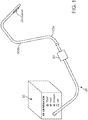
- Figure 1 shows a system for recanalizing occluded vessels using RF energy.
- the system comprises longitudinal members 100a and 100b for delivering RF energy to an occlusion.
- longitudinal member 100a serves as an antegrade member and longitudinal member 100b serves as a retrograde member.
- An RF generator 10 (also referred to as a controller) serves as the source of RF energy to be provided to longitudinal members 100a and 100b.
- Longitudinal members 100a and 100b may be guidewires, catheters, micro-catheters, or dilating catheters.
- longitudinal members 100a and 100b are guidewires.
- guidewire is used to refer to a longitudinal member 100a or 100b, it is understood that the term “guidewire” as used herein is intended to include any other type of longitudinal member.
- a pigtail 20 connects at its proximal end to the RF generator 10 and terminates at its distal end in a connector 30.
- Connector 30 is a standard connector that couples the input and output signals of the RF generator 10 to the guidewires 100a and 100b.
- Guidewires 100a and 100b are configured to have sufficient torsional rigidity and longitudinal flexibility to advance through an occlusion, and to align their electrodes in a direction away from the vessel wall, towards the other longitudinal member, or any combination thereof.
- the antegrade and retrograde guidewires 100a and 100b have conductive electrodes 105a and 105b, respectively, at their distal ends.
- the electrodes 105a and 105b are located on one side of their respective guidewires 100a and 100b, thereby providing the operating physician with the freedom to allow the electrode-free side of the guidewire to touch the vessel wall (if needed) while still directing the RF energy away from the vessel wall. Additionally, this allows the configuration to direct the RF energy away from the vessel wall, thereby minimizing potential RF injury to the vessel wall.
- one or more of the guidewires comprises a plurality of electrodes arranged in an array.
- Conductive wires (not shown) connect the electrodes 105a and 105b to connector 30 to deliver RF energy from the RF generator 10 to the electrodes 105a and 105.
- the exterior of the guidewires are covered by non-conductive layers 115a and 115b, respectively, that sandwich the conductive wires between the guidewires and the non-conductive layers.
- the non-conductive layers 115a and 115b comprise a sheath or a coating.
- the guidewires 100a and 100b comprise temperature measuring elements 110a and 110b at the distal tip of the antegrade and retrograde guidewires, respectively.
- the temperature measuring elements 110a and 110b comprise thermocouples or thermistors that are connected to the connector 30.
- pressure measuring elements are placed on the distal ends of the guidewires to detect a change in pressure upon activation of the RF energy.
- RF generator 10 is configured to allow the user to set a maximum temperature, a treatment time period, a level of RF power, or a combination of these control parameters.
- the treatment time period indicates the period of time over which the RF energy will flow between the electrodes.
- the maximum temperature setting serves as a threshold temperature for the tissue that is in contact with the electrodes, and the RF generator 10 can be set to reduce or shut off power to one or both electrodes when one or more of the temperature measuring elements 110a and 110b indicate a tissue temperature at or near the threshold.
- the generator 10 is capable of measuring the impedance of the tissue between the two electrodes 105a and 105b. Based on the type of the occlusion (i.e., the nature of the calcified material), the user can choose the appropriate combination of temperature, treatment time, and the amount of RF energy to be provided to the tissue to achieve a safe and effective treatment. Alternatively, the treatment may proceed with the user manually controlling the parameters during the recanalization procedure, with the user treating the occlusion until recanalization is achieved.
- the type of the occlusion i.e., the nature of the calcified material
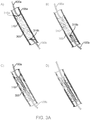
- FIGS 3A and 3B The sequence of the recanalization treatment steps are illustrated in Figures 3A and 3B .
- the antegrade guidewire 100a and retrograde guidewire 100b are advanced to the proximal and distal ends 310a and 310b of the occlusion 310, respectively. This can be accomplished using standard angioplasty techniques.
- the retrograde guidewire can be advanced to the distal end of the occlusion 310b using collaterals such as the septals.
- the RF treatment is initiated.
- the guidewires are advanced as deep into the occlusion as possible to minimize the distance between the electrodes and, consequently, minimize the length of the ablation zone.
- Confirmation that the guidewires 100a and 100b are in an appropriate position can be generated by impedance measurements and/or by using any of the standard imaging techniques employed during interventional procedures, such as fluoroscopy or intravascular ultrasound (IVUS), in which transducers are placed on the distal ends of the guidewire.
- the calcified occlusion 310 generally exhibits significantly higher impedance than the vessel wall 300. If an impedance measurement indicates a low impedance value, it is likely that one or both guidewires are in contact with the vessel wall 300, and appropriate repositioning of the guidewires may be warranted.
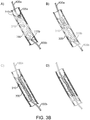
- the occlusion 310 Upon initiating the recanalization RF treatment, the occlusion 310 is ablated from the ends 310a and 310b of the occlusion 310 to the interior of the occlusion 310, as shown in Figure 3A diagram B. The user then slowly and carefully advances one or both guidewires 100a and 100b until a channel or path is created in the occlusion 310, as shown in Figure 3A diagram C. As shown in Figure 3A , the antegrade guidewire 100a may be kept stationary and the retrograde guidewire 100b may be advanced through the occlusion 310.
- the retrograde guidewire 100b may be withdrawn and the antegrade guidewire 100a may be advanced through the occlusion 310, as shown in Figure 3A diagram D, and standard interventional procedures, such as balloon angioplasty, can be performed.
- the retrograde guidewire 100b can be kept stationary during the RF treatment and the antegrade guidewire 100a can be advanced through the occlusion 310. This is illustrated in Figure 3B diagrams A - D.
- the catheter comprises a means for removing or withdrawing debris resulting from the RF ablation.
- a mechanism could be provided to capture and retrieve the debris, or a suction device could be provided to actively remove the debris near the ablation area.
- embolic protection mechanisms are disclosed in the above referenced co-pending US Patent Application Serial Number 11/706,041 .
- Figure 4 shows an example embodiment of a longitudinal member 400 comprising an embolic protection mechanism 410.
- the embolic protection mechanism 410 comprises filter, mesh, net, or similar element, for capturing and retrieving ablation debris.
- the embolic protection may comprise a balloon for occluding the vessel and preventing the debris from circulating, and for subsequent aspiration of the debris through a longitudinal member.
- a sheath may also be configured to be or to include a debris capture and retrieval mechanism or a suction device.
- a longitudinal member may be retracted, and the remaining sheath may be used as a capture and retrieval mechanism or a suction device to remove ablation debris.
- the longitudinal member comprises an ablating wire housed in the lumen of a dilating catheter. Upon ablation, the ablating wire may be retracted and the dilating catheter may be used to remove the debris.
- the system comprises a separate catheter to provide suction, or otherwise capture and remove the debris from the ablation site.
- the device may be coupled to an electrocardiogram (EKG) machine to aid in timing energy emissions.
- EKG electrocardiogram
- the rate of blood flow through the coronary arteries typically varies during the cardiac cycle.
- flow through the arteries is generally lower than during diastole.
- energy emission is timed during diastole, for example using an algorithm to detect the R-wave of an EKG, and energy emission is timed to occur when flow is highest, thereby maximizing the cooling effect provided by blood flow and consequently minimizing the heat exposure to the vessel.
- coronary artery dimensions can vary during the cardiac cycle and energy emission can similarly be timed to take advantage of this fact.
- the device comprises a mechanism for detecting or estimating the distance between the electrodes, and for decreasing the amount of delivered RF energy as the distance between the electrodes decreases, thereby minimizing potential RF injury to the vessel wall.
- the device is an ablation catheter comprising a longitudinal member having a distal end, a proximal end, and a guidewire shaft there-between comprising a guidewire lumen.
- the longitudinal member is a dilating catheter and is structurally configured along at least part of the length of the catheter to enable advancement or alignment of the longitudinal member through a narrow diameter blood vessel or occlusion. Advancement is achieved, for example, by turning or twisting the longitudinal member.
- Figures 5A-C show such an embodiment of the present invention.
- the longitudinal member 500 may comprise a helical exterior 501 that advances through the vessel and dilates the vessel as the member is being twisted or rotated.
- Helical exterior 501 comprises a plurality of grooves 502 carved into the outer body of the longitudinal member 500.
- the distal tip of longitudinal member 500 optionally comprises a radiopaque marker 510.
- An electrode 520 is located at or near the distal end of the catheter.
- Figure 5B the cross section of which is shown in Figure 5C .
- the longitudinal member 550 may comprise a plurality of wires 551 and 552 wound around a liner 565. In one embodiment, the wires 551 and 552 comprise at least two different diameters. Longitudinal member 550 optionally terminates at a marker 570.
- An electrode 580 is located at or near the distal end of the longitudinal member 550.
- the ablation catheter additionally and optionally comprises conductive wires for transmitting energy between the electrode and an external energy source.
- the plurality of wires may be configured to act as the electrode or conductive wires.
- the catheter comprises an insulating sheath 560 which is optionally retractable.
- the guidewires and electrodes may be made from any one or more suitable materials as is commonly known in the art. Examples of such suitable materials include stainless steel, Nitinol, Elgiloy, platinum, iridium, tantalum, titanium, cobalt, chromium, or any combinations thereof.
- one or more of the guidewires may be made of a polymer, with an electrically conductive core for transmitting electrical energy to the respective electrodes.
- one or more longitudinal members of the recanalization systems of the present invention comprise one or more ultrasound transducers, instead of or in addition to RF electrodes.
- the ultrasound transducers provide ultrasound energy for ablating an occlusion.
- both the antegrade and the retrograde longitudinal members comprise ultrasound transducers and ablate the lesion from an antegrade as well as a retrograde direction.
- Other energy modalities could include microwave and laser.
Claims (9)
- Rekanalisationssystem, umfassend:einen Hochfrequenzgenerator (10);ein antegrades Längselement (110a) mit einem proximalen Ende und einem distalen Ende, wobei das distale Ende des antegraden Längselements eine erste leitfähige Elektrode (105a) umfasst, die dazu ausgelegt ist, an einem distalen Ende einer Okklusion in einem Blutgefäß positioniert zu sein, und wobei das proximale Ende des antegraden Längselements dazu ausgelegt ist, mit dem Hochfrequenzgenerator gekoppelt zu sein; undein retrogrades Längselement (100b) mit einem proximalen Ende und einem distalen Ende, wobei das retrograde Längselement dazu ausgelegt ist, an dem entgegengesetzten proximalen Ende der Okklusion in dem Blutgefäß positioniert zu sein;wobei das distale Ende des retrograden Längselements eine zweite leitfähige Elektrode (105b) umfasst, die dazu ausgelegt ist, die Okklusion durch Hochfrequenzbehandlung von den entgegengesetzten Enden zum Inneren der Okklusion innerhalb des Blutgefäßes abzutragen, und wobei das proximale Ende des retrograden Längselements dazu ausgelegt ist, mit dem Hochfrequenzgenerator gekoppelt zu sein;wobei der Hochfrequenzgenerator Hochfrequenzenergie an die erste und/oder die zweite leitfähige Elektrode liefert, um eine bipolare Anordnung zwischen den Elektroden zur Erzeugung eines Kanals wenigstens teilweise durch die Okklusion hindurch bereitzustellen, undwobei die Längselemente ausreichende Torsionssteifigkeit und Längsflexibilität haben, um durch eine Okklusion hindurch zu dringen und die Elektroden weg von den Gefäßwänden und aufeinander zu auszurichten.
- System nach Anspruch 1, wobei das antegrade und das retrograde Längselement (100a, 100b) Führungsdrähte, Katheter, Mikrokatheter oder dilatierende Katheter sind.
- System nach Anspruch 1, wobei sowohl die erste als auch zweite Elektrode (105a, 105b) an einer Seite des jeweiligen antegraden und retrograden Längselements montiert ist.
- System nach Anspruch 1, wobei die erste und die zweite Elektrode (105a, 105b) in einem Array angeordnet sind.
- System nach Anspruch 1, wobei das antegrade und/oder das retrograde Längselement (100a, 100b) einen Embolieschutzmechanismus (410) zum Auffangen und Herausholen von Bruchstücken umfasst.
- System nach Anspruch 5, wobei der Embolieschützmechanismus (410) einen Filter, einen Ballon oder ein Lumen in dem retrograden und/oder dem antegraden Längselement umfasst, das eine Absaugung erlaubt.
- System nach Anspruch 1, wobei der Hochfrequenzgenerator (10) dazu ausgelegt ist, die Hochfrequenzenergie zu liefern, wenn der Blutstrom im Gefäß am höchsten ist, um den durch den Blutstrom bereitgestellten Kühlungseffekt zu verstärken und eine Hitzeeinwirkung auf das Gefäß zu reduzieren.
- System nach Anspruch 1, ferner umfassend einen Verbindungsanschluss in dem Hochfrequenzgenerator (10), der für eine Verbindung mit einem EKG ausgelegt ist, um durch den Hochfrequenzgenerator zugeführte Energie zeitlich festzulegen.
- System nach Anspruch 8, wobei der Hochfrequenzgenerator (10) dazu ausgelegt ist, die R-Welle eines EKG in Verbindung mit der zeitlichen Festlegung der Energiezufuhr zu erfassen.
Priority Applications (1)
| Application Number | Priority Date | Filing Date | Title |
|---|---|---|---|
| EP18154292.9A EP3348221A1 (de) | 2007-09-26 | 2008-09-23 | Neukanalisierung verstopfter gefässe mithilfe von hochfrequenzenergie |
Applications Claiming Priority (2)
| Application Number | Priority Date | Filing Date | Title |
|---|---|---|---|
| US97547307P | 2007-09-26 | 2007-09-26 | |
| PCT/US2008/077403 WO2009042614A1 (en) | 2007-09-26 | 2008-09-23 | Recanalizing occluded vessels using radiofrequency energy |
Related Child Applications (1)
| Application Number | Title | Priority Date | Filing Date |
|---|---|---|---|
| EP18154292.9A Division EP3348221A1 (de) | 2007-09-26 | 2008-09-23 | Neukanalisierung verstopfter gefässe mithilfe von hochfrequenzenergie |
Publications (3)
| Publication Number | Publication Date |
|---|---|
| EP2197383A1 EP2197383A1 (de) | 2010-06-23 |
| EP2197383A4 EP2197383A4 (de) | 2012-08-22 |
| EP2197383B1 true EP2197383B1 (de) | 2018-01-31 |
Family
ID=40511823
Family Applications (2)
| Application Number | Title | Priority Date | Filing Date |
|---|---|---|---|
| EP08834456.9A Active EP2197383B1 (de) | 2007-09-26 | 2008-09-23 | Rekanalisation von verschlossenen gefässen mit hochfrequenz-energie |
| EP18154292.9A Pending EP3348221A1 (de) | 2007-09-26 | 2008-09-23 | Neukanalisierung verstopfter gefässe mithilfe von hochfrequenzenergie |
Family Applications After (1)
| Application Number | Title | Priority Date | Filing Date |
|---|---|---|---|
| EP18154292.9A Pending EP3348221A1 (de) | 2007-09-26 | 2008-09-23 | Neukanalisierung verstopfter gefässe mithilfe von hochfrequenzenergie |
Country Status (7)
| Country | Link |
|---|---|
| US (1) | US8911435B2 (de) |
| EP (2) | EP2197383B1 (de) |
| JP (4) | JP5618332B2 (de) |
| KR (1) | KR101228879B1 (de) |
| AU (1) | AU2008304599B2 (de) |
| CA (2) | CA3024053C (de) |
| WO (1) | WO2009042614A1 (de) |
Families Citing this family (37)
| Publication number | Priority date | Publication date | Assignee | Title |
|---|---|---|---|---|
| US6723063B1 (en) | 1998-06-29 | 2004-04-20 | Ekos Corporation | Sheath for use with an ultrasound element |
| US6582392B1 (en) | 1998-05-01 | 2003-06-24 | Ekos Corporation | Ultrasound assembly for use with a catheter |
| ATE520362T1 (de) | 2001-12-03 | 2011-09-15 | Ekos Corp | Katheter mit mehreren ultraschall-abstrahlenden teilen |
| US8226629B1 (en) | 2002-04-01 | 2012-07-24 | Ekos Corporation | Ultrasonic catheter power control |
| US9107590B2 (en) | 2004-01-29 | 2015-08-18 | Ekos Corporation | Method and apparatus for detecting vascular conditions with a catheter |
| US9119651B2 (en) * | 2006-02-13 | 2015-09-01 | Retro Vascular, Inc. | Recanalizing occluded vessels using controlled antegrade and retrograde tracking |
| JP4932854B2 (ja) * | 2006-02-13 | 2012-05-16 | レトロ・ヴァスキュラー・インコーポレーテッド | カテーテルシステム |
| EP2015846A2 (de) | 2006-04-24 | 2009-01-21 | Ekos Corporation | Ultraschalltherapiesystem |
| EP2111261B1 (de) | 2007-01-08 | 2015-04-15 | Ekos Corporation | Leistungsparameter für einen ultraschallkatheter |
| US10182833B2 (en) | 2007-01-08 | 2019-01-22 | Ekos Corporation | Power parameters for ultrasonic catheter |
| EP2494932B1 (de) | 2007-06-22 | 2020-05-20 | Ekos Corporation | Vorrichtung zur Behandlung von intrakranialen Blutungen |
| US9561073B2 (en) | 2007-09-26 | 2017-02-07 | Retrovascular, Inc. | Energy facilitated composition delivery |
| US9283034B2 (en) * | 2007-09-26 | 2016-03-15 | Retrovascular, Inc. | Recanalization system using radiofrequency energy |
| WO2009042614A1 (en) * | 2007-09-26 | 2009-04-02 | Retro Vascular, Inc. | Recanalizing occluded vessels using radiofrequency energy |
| EP2448636B1 (de) | 2009-07-03 | 2014-06-18 | Ekos Corporation | Leistungsparameter für einen ultraschallkatheter |
| US8740835B2 (en) | 2010-02-17 | 2014-06-03 | Ekos Corporation | Treatment of vascular occlusions using ultrasonic energy and microbubbles |
| JP6291253B2 (ja) | 2010-08-27 | 2018-03-14 | イーコス・コーポレイシヨン | 超音波カテーテル |
| CN112401981B (zh) | 2010-11-16 | 2024-03-08 | Tva医疗公司 | 用于形成瘘管的装置和方法 |
| US11458290B2 (en) | 2011-05-11 | 2022-10-04 | Ekos Corporation | Ultrasound system |
| WO2013013248A2 (en) * | 2011-07-20 | 2013-01-24 | Retrovascular, Inc. | Energy facilitated composition delivery |
| AU2013328944B2 (en) | 2012-10-11 | 2018-05-24 | Tva Medical, Inc. | Devices and methods for fistula formation |
| CN105228683B (zh) | 2013-03-14 | 2022-06-10 | Tva医疗公司 | 瘘管形成装置和用于形成瘘管的方法 |
| SG11201506154RA (en) | 2013-03-14 | 2015-09-29 | Ekos Corp | Method and apparatus for drug delivery to a target site |
| US9084620B2 (en) * | 2013-03-14 | 2015-07-21 | DePuy Synthes Products, Inc. | Detection and clearing of occlusions in catheters |
| WO2015138998A1 (en) | 2014-03-14 | 2015-09-17 | Tva Medical, Inc. | Fistula formation devices and methods therefor |
| WO2016033374A1 (en) | 2014-08-27 | 2016-03-03 | Tva Medical, Inc. | Cryolipopysis devices and methods therefor |
| US10092742B2 (en) | 2014-09-22 | 2018-10-09 | Ekos Corporation | Catheter system |
| DE102015117171B4 (de) | 2014-10-09 | 2019-03-21 | Denso Corporation | Batteriezustandsabschätzvorrichtung |
| US10603040B1 (en) | 2015-02-09 | 2020-03-31 | Tva Medical, Inc. | Methods for treating hypertension and reducing blood pressure with formation of fistula |
| CN107708581B (zh) | 2015-06-10 | 2021-11-19 | Ekos公司 | 超声波导管 |
| US10874422B2 (en) | 2016-01-15 | 2020-12-29 | Tva Medical, Inc. | Systems and methods for increasing blood flow |
| MX2018008565A (es) | 2016-01-15 | 2018-08-23 | Tva Medical Inc | Dispositivos y metodos para formar una fistula. |
| WO2017124059A1 (en) | 2016-01-15 | 2017-07-20 | Tva Medical, Inc. | Devices and methods for advancing a wire |
| EP3515322B1 (de) | 2016-09-25 | 2022-04-20 | TVA Medical, Inc. | Gefässstentvorrichtungen |
| WO2019121446A1 (en) | 2017-12-21 | 2019-06-27 | Sanofi | Transmission of data associated with an injection device usage using passive rf modulation |
| US11865312B2 (en) | 2017-12-21 | 2024-01-09 | Sanofi | RFID dose tracking mechanism for injection devices |
| WO2020183534A1 (ja) * | 2019-03-08 | 2020-09-17 | オリンパス株式会社 | 血管内視鏡装置および血管内視鏡システム |
Citations (2)
| Publication number | Priority date | Publication date | Assignee | Title |
|---|---|---|---|---|
| US20020072740A1 (en) * | 2000-12-11 | 2002-06-13 | Scimed Life Systems, Inc. | Radio frequency ablation system |
| US20070208368A1 (en) * | 2006-02-13 | 2007-09-06 | Osamu Katoh | Recanalizing occluded vessels using controlled antegrade and retrograde tracking |
Family Cites Families (57)
| Publication number | Priority date | Publication date | Assignee | Title |
|---|---|---|---|---|
| US3868956A (en) * | 1972-06-05 | 1975-03-04 | Ralph J Alfidi | Vessel implantable appliance and method of implanting it |
| US5041109A (en) * | 1986-10-27 | 1991-08-20 | University Of Florida | Laser apparatus for the recanalization of vessels and the treatment of other cardiac conditions |
| DE3803697A1 (de) * | 1988-02-08 | 1989-08-17 | Wolfgang Arno Karl Dr Radtke | Laser - valvotomie - katheter (herzkatheter zur perkutanen gezielten valvotomie verengter herzklappen) |
| US4998933A (en) * | 1988-06-10 | 1991-03-12 | Advanced Angioplasty Products, Inc. | Thermal angioplasty catheter and method |
| US5749914A (en) * | 1989-01-06 | 1998-05-12 | Advanced Coronary Intervention | Catheter for obstructed stent |
| US5324255A (en) * | 1991-01-11 | 1994-06-28 | Baxter International Inc. | Angioplasty and ablative devices having onboard ultrasound components and devices and methods for utilizing ultrasound to treat or prevent vasopasm |
| US5366443A (en) | 1992-01-07 | 1994-11-22 | Thapliyal And Eggers Partners | Method and apparatus for advancing catheters through occluded body lumens |
| US5419767A (en) * | 1992-01-07 | 1995-05-30 | Thapliyal And Eggers Partners | Methods and apparatus for advancing catheters through severely occluded body lumens |
| EP0597195B1 (de) * | 1992-08-18 | 1999-07-21 | The Spectranetics Corporation | Führungsdraht mit Faseroptik |
| JPH0698937A (ja) * | 1992-09-18 | 1994-04-12 | Inter Noba Kk | ホットバルーンカテーテル |
| JPH06125915A (ja) * | 1992-10-21 | 1994-05-10 | Inter Noba Kk | カテーテル式医療機器 |
| US5501694A (en) * | 1992-11-13 | 1996-03-26 | Scimed Life Systems, Inc. | Expandable intravascular occlusion material removal devices and methods of use |
| WO1995001751A1 (en) * | 1993-07-01 | 1995-01-19 | Boston Scientific Corporation | Imaging, electrical potential sensing, and ablation catheters |
| US5507769A (en) * | 1994-10-18 | 1996-04-16 | Stentco, Inc. | Method and apparatus for forming an endoluminal bifurcated graft |
| US5624430A (en) * | 1994-11-28 | 1997-04-29 | Eton; Darwin | Magnetic device to assist transcorporeal guidewire placement |
| JPH0956825A (ja) * | 1995-08-24 | 1997-03-04 | Nissho Corp | ホットバルーンカテーテル |
| JPH09135908A (ja) * | 1995-11-17 | 1997-05-27 | Aloka Co Ltd | 超音波診断治療システム |
| US5895398A (en) * | 1996-02-02 | 1999-04-20 | The Regents Of The University Of California | Method of using a clot capture coil |
| US6652546B1 (en) * | 1996-07-26 | 2003-11-25 | Kensey Nash Corporation | System and method of use for revascularizing stenotic bypass grafts and other occluded blood vessels |
| US5882329A (en) * | 1997-02-12 | 1999-03-16 | Prolifix Medical, Inc. | Apparatus and method for removing stenotic material from stents |
| EP0998248A4 (de) * | 1997-06-13 | 2001-03-21 | Arthrocare Corp | Elektrochirurgische vorrichtungen und verfahren zur rekanalisation von okkludierten körperlumen |
| US5851185A (en) * | 1997-07-02 | 1998-12-22 | Cabot Technology Corporation | Apparatus for alignment of tubular organs |
| US7037316B2 (en) * | 1997-07-24 | 2006-05-02 | Mcguckin Jr James F | Rotational thrombectomy device |
| US6068688A (en) | 1997-11-12 | 2000-05-30 | Cabot Corporation | Particle having an attached stable free radical and methods of making the same |
| US20050171478A1 (en) * | 1998-01-13 | 2005-08-04 | Selmon Matthew R. | Catheter system for crossing total occlusions in vasculature |
| US6068648A (en) * | 1998-01-26 | 2000-05-30 | Orthodyne, Inc. | Tissue anchoring system and method |
| US6210400B1 (en) * | 1998-07-22 | 2001-04-03 | Endovasix, Inc. | Flexible flow apparatus and method for the disruption of occlusions |
| US6241744B1 (en) | 1998-08-14 | 2001-06-05 | Fox Hollow Technologies, Inc. | Apparatus for deploying a guidewire across a complex lesion |
| JP3214454B2 (ja) * | 1998-09-03 | 2001-10-02 | 日本電気株式会社 | プログラム内蔵方式パケット処理装置 |
| US6475222B1 (en) * | 1998-11-06 | 2002-11-05 | St. Jude Medical Atg, Inc. | Minimally invasive revascularization apparatus and methods |
| US6911026B1 (en) * | 1999-07-12 | 2005-06-28 | Stereotaxis, Inc. | Magnetically guided atherectomy |
| US6068645A (en) * | 1999-06-07 | 2000-05-30 | Tu; Hosheng | Filter system and methods for removing blood clots and biological material |
| US6235044B1 (en) * | 1999-08-04 | 2001-05-22 | Scimed Life Systems, Inc. | Percutaneous catheter and guidewire for filtering during ablation of mycardial or vascular tissue |
| US6454775B1 (en) * | 1999-12-06 | 2002-09-24 | Bacchus Vascular Inc. | Systems and methods for clot disruption and retrieval |
| US6394956B1 (en) * | 2000-02-29 | 2002-05-28 | Scimed Life Systems, Inc. | RF ablation and ultrasound catheter for crossing chronic total occlusions |
| US6416523B1 (en) | 2000-10-03 | 2002-07-09 | Scimed Life Systems, Inc. | Method and apparatus for creating channels through vascular total occlusions |
| WO2002089686A1 (en) * | 2001-05-10 | 2002-11-14 | Rita Medical Systems, Inc. | Rf tissue ablation apparatus and method |
| US20040230219A1 (en) * | 2003-05-12 | 2004-11-18 | Roucher Leo R. | Anchoring, supporting and centering catheter system for treating chronic total occlusions |
| EP1684655A2 (de) * | 2003-11-18 | 2006-08-02 | SciMed Life Systems, Inc. | System und verfahren für die gewebeablation |
| US20050154400A1 (en) * | 2003-12-18 | 2005-07-14 | Asahi Intecc Co., Ltd | Medical treating tool |
| US7704249B2 (en) * | 2004-05-07 | 2010-04-27 | Arthrocare Corporation | Apparatus and methods for electrosurgical ablation and resection of target tissue |
| US8545418B2 (en) * | 2004-08-25 | 2013-10-01 | Richard R. Heuser | Systems and methods for ablation of occlusions within blood vessels |
| US20080154153A1 (en) * | 2004-08-25 | 2008-06-26 | Heuser Richard R | Multiple-wire systems and methods for ablation of occlusions within blood vessels |
| US7335197B2 (en) * | 2004-10-13 | 2008-02-26 | Medtronic, Inc. | Transurethral needle ablation system with flexible catheter tip |
| US8007440B2 (en) * | 2005-02-08 | 2011-08-30 | Volcano Corporation | Apparatus and methods for low-cost intravascular ultrasound imaging and for crossing severe vascular occlusions |
| US7727187B2 (en) * | 2005-04-04 | 2010-06-01 | Cook Incorporated | Scored catheter device |
| AU2006262447A1 (en) * | 2005-06-20 | 2007-01-04 | Medtronic Ablation Frontiers Llc | Ablation catheter |
| US20070043389A1 (en) * | 2005-08-05 | 2007-02-22 | Shintech, Llc | System for treating chronic total occlusion caused by lower extremity arterial disease |
| US7374567B2 (en) * | 2006-01-25 | 2008-05-20 | Heuser Richard R | Catheter system for connecting adjacent blood vessels |
| US9119651B2 (en) * | 2006-02-13 | 2015-09-01 | Retro Vascular, Inc. | Recanalizing occluded vessels using controlled antegrade and retrograde tracking |
| US8206370B2 (en) * | 2006-04-21 | 2012-06-26 | Abbott Laboratories | Dual lumen guidewire support catheter |
| WO2008022077A2 (en) * | 2006-08-14 | 2008-02-21 | Buch Wally S | Methods and apparatus for mitral valve repair |
| WO2008022148A2 (en) * | 2006-08-14 | 2008-02-21 | Stereotaxis, Inc. | Method and apparatus for ablative recanalization of blocked vasculature |
| US20080312673A1 (en) * | 2007-06-05 | 2008-12-18 | Viswanathan Raju R | Method and apparatus for CTO crossing |
| US9283034B2 (en) * | 2007-09-26 | 2016-03-15 | Retrovascular, Inc. | Recanalization system using radiofrequency energy |
| WO2009042614A1 (en) | 2007-09-26 | 2009-04-02 | Retro Vascular, Inc. | Recanalizing occluded vessels using radiofrequency energy |
| EP3446649B1 (de) * | 2011-09-19 | 2020-05-20 | Boston Scientific Scimed, Inc. | Subintimaler wiedereintrittskatheter |
-
2008
- 2008-09-23 WO PCT/US2008/077403 patent/WO2009042614A1/en active Application Filing
- 2008-09-23 EP EP08834456.9A patent/EP2197383B1/de active Active
- 2008-09-23 CA CA3024053A patent/CA3024053C/en active Active
- 2008-09-23 US US12/680,500 patent/US8911435B2/en active Active
- 2008-09-23 KR KR1020107008803A patent/KR101228879B1/ko active IP Right Grant
- 2008-09-23 JP JP2010527088A patent/JP5618332B2/ja active Active
- 2008-09-23 CA CA2700968A patent/CA2700968C/en active Active
- 2008-09-23 AU AU2008304599A patent/AU2008304599B2/en active Active
- 2008-09-23 EP EP18154292.9A patent/EP3348221A1/de active Pending
-
2014
- 2014-06-17 JP JP2014124232A patent/JP6050283B2/ja active Active
-
2016
- 2016-11-24 JP JP2016227657A patent/JP6461891B2/ja active Active
-
2018
- 2018-12-25 JP JP2018240919A patent/JP6785832B2/ja active Active
Patent Citations (2)
| Publication number | Priority date | Publication date | Assignee | Title |
|---|---|---|---|---|
| US20020072740A1 (en) * | 2000-12-11 | 2002-06-13 | Scimed Life Systems, Inc. | Radio frequency ablation system |
| US20070208368A1 (en) * | 2006-02-13 | 2007-09-06 | Osamu Katoh | Recanalizing occluded vessels using controlled antegrade and retrograde tracking |
Also Published As
| Publication number | Publication date |
|---|---|
| JP5618332B2 (ja) | 2014-11-05 |
| JP2010540099A (ja) | 2010-12-24 |
| JP2017094092A (ja) | 2017-06-01 |
| JP2019076741A (ja) | 2019-05-23 |
| AU2008304599A1 (en) | 2009-04-02 |
| CA2700968A1 (en) | 2009-04-02 |
| EP2197383A1 (de) | 2010-06-23 |
| WO2009042614A1 (en) | 2009-04-02 |
| CA2700968C (en) | 2019-06-11 |
| EP3348221A1 (de) | 2018-07-18 |
| AU2008304599B2 (en) | 2012-11-22 |
| JP6785832B2 (ja) | 2020-11-18 |
| US20100292685A1 (en) | 2010-11-18 |
| US8911435B2 (en) | 2014-12-16 |
| JP2014208263A (ja) | 2014-11-06 |
| JP6050283B2 (ja) | 2016-12-21 |
| JP6461891B2 (ja) | 2019-01-30 |
| KR101228879B1 (ko) | 2013-02-05 |
| CA3024053A1 (en) | 2009-04-02 |
| CA3024053C (en) | 2021-12-07 |
| EP2197383A4 (de) | 2012-08-22 |
| KR20100075528A (ko) | 2010-07-02 |
Similar Documents
| Publication | Publication Date | Title |
|---|---|---|
| EP2197383B1 (de) | Rekanalisation von verschlossenen gefässen mit hochfrequenz-energie | |
| US9283034B2 (en) | Recanalization system using radiofrequency energy | |
| US10779884B2 (en) | Energy facilitated composition delivery | |
| EP3209362B1 (de) | Abgabekatheter mit neuausrichtungsvorrichtung | |
| WO2013013248A2 (en) | Energy facilitated composition delivery | |
| AU2011235882A1 (en) | Recanalizing occluded vessels using radiofrequency energy |
Legal Events
| Date | Code | Title | Description |
|---|---|---|---|
| PUAI | Public reference made under article 153(3) epc to a published international application that has entered the european phase |
Free format text: ORIGINAL CODE: 0009012 |
|
| 17P | Request for examination filed |
Effective date: 20100415 |
|
| AK | Designated contracting states |
Kind code of ref document: A1 Designated state(s): AT BE BG CH CY CZ DE DK EE ES FI FR GB GR HR HU IE IS IT LI LT LU LV MC MT NL NO PL PT RO SE SI SK TR |
|
| AX | Request for extension of the european patent |
Extension state: AL BA MK RS |
|
| RIN1 | Information on inventor provided before grant (corrected) |
Inventor name: OGATA, WAYNE Inventor name: KATOH, OSAMU |
|
| DAX | Request for extension of the european patent (deleted) | ||
| A4 | Supplementary search report drawn up and despatched |
Effective date: 20120724 |
|
| RIC1 | Information provided on ipc code assigned before grant |
Ipc: A61B 18/20 20060101AFI20120718BHEP Ipc: A61B 18/18 20060101ALN20120718BHEP |
|
| 17Q | First examination report despatched |
Effective date: 20161004 |
|
| STAA | Information on the status of an ep patent application or granted ep patent |
Free format text: STATUS: EXAMINATION IS IN PROGRESS |
|
| RIC1 | Information provided on ipc code assigned before grant |
Ipc: A61B 18/20 20060101AFI20170718BHEP Ipc: A61B 18/18 20060101ALN20170718BHEP |
|
| RIC1 | Information provided on ipc code assigned before grant |
Ipc: A61B 18/20 20060101AFI20170727BHEP Ipc: A61B 18/18 20060101ALN20170727BHEP |
|
| GRAP | Despatch of communication of intention to grant a patent |
Free format text: ORIGINAL CODE: EPIDOSNIGR1 |
|
| STAA | Information on the status of an ep patent application or granted ep patent |
Free format text: STATUS: GRANT OF PATENT IS INTENDED |
|
| RIN1 | Information on inventor provided before grant (corrected) |
Inventor name: OGATA, WAYNE Inventor name: KATOH, OSAMU |
|
| RAP1 | Party data changed (applicant data changed or rights of an application transferred) |
Owner name: RETROVASCULAR, INC. |
|
| INTG | Intention to grant announced |
Effective date: 20170912 |
|
| RIN1 | Information on inventor provided before grant (corrected) |
Inventor name: OGATA, WAYNE Inventor name: KATOH, OSAMU |
|
| GRAS | Grant fee paid |
Free format text: ORIGINAL CODE: EPIDOSNIGR3 |
|
| GRAA | (expected) grant |
Free format text: ORIGINAL CODE: 0009210 |
|
| STAA | Information on the status of an ep patent application or granted ep patent |
Free format text: STATUS: THE PATENT HAS BEEN GRANTED |
|
| AK | Designated contracting states |
Kind code of ref document: B1 Designated state(s): AT BE BG CH CY CZ DE DK EE ES FI FR GB GR HR HU IE IS IT LI LT LU LV MC MT NL NO PL PT RO SE SI SK TR |
|
| REG | Reference to a national code |
Ref country code: GB Ref legal event code: FG4D Ref country code: CH Ref legal event code: EP |
|
| REG | Reference to a national code |
Ref country code: AT Ref legal event code: REF Ref document number: 966639 Country of ref document: AT Kind code of ref document: T Effective date: 20180215 |
|
| REG | Reference to a national code |
Ref country code: IE Ref legal event code: FG4D |
|
| REG | Reference to a national code |
Ref country code: DE Ref legal event code: R096 Ref document number: 602008053933 Country of ref document: DE |
|
| REG | Reference to a national code |
Ref country code: NL Ref legal event code: FP |
|
| REG | Reference to a national code |
Ref country code: DE Ref legal event code: R081 Ref document number: 602008053933 Country of ref document: DE Owner name: RETROVASCULAR, INC., PLEASANTON, US Free format text: FORMER OWNER: RETROVASCULAR, INC., SAN RAMON, CALIF., US |
|
| RAP2 | Party data changed (patent owner data changed or rights of a patent transferred) |
Owner name: RETROVASCULAR, INC. |
|
| REG | Reference to a national code |
Ref country code: LT Ref legal event code: MG4D |
|
| REG | Reference to a national code |
Ref country code: AT Ref legal event code: MK05 Ref document number: 966639 Country of ref document: AT Kind code of ref document: T Effective date: 20180131 |
|
| PG25 | Lapsed in a contracting state [announced via postgrant information from national office to epo] |
Ref country code: HR Free format text: LAPSE BECAUSE OF FAILURE TO SUBMIT A TRANSLATION OF THE DESCRIPTION OR TO PAY THE FEE WITHIN THE PRESCRIBED TIME-LIMIT Effective date: 20180131 Ref country code: LT Free format text: LAPSE BECAUSE OF FAILURE TO SUBMIT A TRANSLATION OF THE DESCRIPTION OR TO PAY THE FEE WITHIN THE PRESCRIBED TIME-LIMIT Effective date: 20180131 Ref country code: ES Free format text: LAPSE BECAUSE OF FAILURE TO SUBMIT A TRANSLATION OF THE DESCRIPTION OR TO PAY THE FEE WITHIN THE PRESCRIBED TIME-LIMIT Effective date: 20180131 Ref country code: NO Free format text: LAPSE BECAUSE OF FAILURE TO SUBMIT A TRANSLATION OF THE DESCRIPTION OR TO PAY THE FEE WITHIN THE PRESCRIBED TIME-LIMIT Effective date: 20180430 Ref country code: FI Free format text: LAPSE BECAUSE OF FAILURE TO SUBMIT A TRANSLATION OF THE DESCRIPTION OR TO PAY THE FEE WITHIN THE PRESCRIBED TIME-LIMIT Effective date: 20180131 |
|
| PG25 | Lapsed in a contracting state [announced via postgrant information from national office to epo] |
Ref country code: LV Free format text: LAPSE BECAUSE OF FAILURE TO SUBMIT A TRANSLATION OF THE DESCRIPTION OR TO PAY THE FEE WITHIN THE PRESCRIBED TIME-LIMIT Effective date: 20180131 Ref country code: AT Free format text: LAPSE BECAUSE OF FAILURE TO SUBMIT A TRANSLATION OF THE DESCRIPTION OR TO PAY THE FEE WITHIN THE PRESCRIBED TIME-LIMIT Effective date: 20180131 Ref country code: SE Free format text: LAPSE BECAUSE OF FAILURE TO SUBMIT A TRANSLATION OF THE DESCRIPTION OR TO PAY THE FEE WITHIN THE PRESCRIBED TIME-LIMIT Effective date: 20180131 Ref country code: BG Free format text: LAPSE BECAUSE OF FAILURE TO SUBMIT A TRANSLATION OF THE DESCRIPTION OR TO PAY THE FEE WITHIN THE PRESCRIBED TIME-LIMIT Effective date: 20180430 Ref country code: PL Free format text: LAPSE BECAUSE OF FAILURE TO SUBMIT A TRANSLATION OF THE DESCRIPTION OR TO PAY THE FEE WITHIN THE PRESCRIBED TIME-LIMIT Effective date: 20180131 Ref country code: IS Free format text: LAPSE BECAUSE OF FAILURE TO SUBMIT A TRANSLATION OF THE DESCRIPTION OR TO PAY THE FEE WITHIN THE PRESCRIBED TIME-LIMIT Effective date: 20180531 Ref country code: GR Free format text: LAPSE BECAUSE OF FAILURE TO SUBMIT A TRANSLATION OF THE DESCRIPTION OR TO PAY THE FEE WITHIN THE PRESCRIBED TIME-LIMIT Effective date: 20180501 |
|
| REG | Reference to a national code |
Ref country code: FR Ref legal event code: PLFP Year of fee payment: 11 |
|
| PG25 | Lapsed in a contracting state [announced via postgrant information from national office to epo] |
Ref country code: EE Free format text: LAPSE BECAUSE OF FAILURE TO SUBMIT A TRANSLATION OF THE DESCRIPTION OR TO PAY THE FEE WITHIN THE PRESCRIBED TIME-LIMIT Effective date: 20180131 Ref country code: IT Free format text: LAPSE BECAUSE OF FAILURE TO SUBMIT A TRANSLATION OF THE DESCRIPTION OR TO PAY THE FEE WITHIN THE PRESCRIBED TIME-LIMIT Effective date: 20180131 Ref country code: RO Free format text: LAPSE BECAUSE OF FAILURE TO SUBMIT A TRANSLATION OF THE DESCRIPTION OR TO PAY THE FEE WITHIN THE PRESCRIBED TIME-LIMIT Effective date: 20180131 |
|
| REG | Reference to a national code |
Ref country code: DE Ref legal event code: R097 Ref document number: 602008053933 Country of ref document: DE |
|
| PG25 | Lapsed in a contracting state [announced via postgrant information from national office to epo] |
Ref country code: CZ Free format text: LAPSE BECAUSE OF FAILURE TO SUBMIT A TRANSLATION OF THE DESCRIPTION OR TO PAY THE FEE WITHIN THE PRESCRIBED TIME-LIMIT Effective date: 20180131 Ref country code: DK Free format text: LAPSE BECAUSE OF FAILURE TO SUBMIT A TRANSLATION OF THE DESCRIPTION OR TO PAY THE FEE WITHIN THE PRESCRIBED TIME-LIMIT Effective date: 20180131 Ref country code: SK Free format text: LAPSE BECAUSE OF FAILURE TO SUBMIT A TRANSLATION OF THE DESCRIPTION OR TO PAY THE FEE WITHIN THE PRESCRIBED TIME-LIMIT Effective date: 20180131 |
|
| PLBE | No opposition filed within time limit |
Free format text: ORIGINAL CODE: 0009261 |
|
| STAA | Information on the status of an ep patent application or granted ep patent |
Free format text: STATUS: NO OPPOSITION FILED WITHIN TIME LIMIT |
|
| 26N | No opposition filed |
Effective date: 20181102 |
|
| PG25 | Lapsed in a contracting state [announced via postgrant information from national office to epo] |
Ref country code: SI Free format text: LAPSE BECAUSE OF FAILURE TO SUBMIT A TRANSLATION OF THE DESCRIPTION OR TO PAY THE FEE WITHIN THE PRESCRIBED TIME-LIMIT Effective date: 20180131 |
|
| PG25 | Lapsed in a contracting state [announced via postgrant information from national office to epo] |
Ref country code: MC Free format text: LAPSE BECAUSE OF FAILURE TO SUBMIT A TRANSLATION OF THE DESCRIPTION OR TO PAY THE FEE WITHIN THE PRESCRIBED TIME-LIMIT Effective date: 20180131 |
|
| REG | Reference to a national code |
Ref country code: CH Ref legal event code: PL |
|
| PG25 | Lapsed in a contracting state [announced via postgrant information from national office to epo] |
Ref country code: LU Free format text: LAPSE BECAUSE OF NON-PAYMENT OF DUE FEES Effective date: 20180923 |
|
| PG25 | Lapsed in a contracting state [announced via postgrant information from national office to epo] |
Ref country code: LI Free format text: LAPSE BECAUSE OF NON-PAYMENT OF DUE FEES Effective date: 20180930 Ref country code: CH Free format text: LAPSE BECAUSE OF NON-PAYMENT OF DUE FEES Effective date: 20180930 |
|
| PG25 | Lapsed in a contracting state [announced via postgrant information from national office to epo] |
Ref country code: MT Free format text: LAPSE BECAUSE OF NON-PAYMENT OF DUE FEES Effective date: 20180923 |
|
| PG25 | Lapsed in a contracting state [announced via postgrant information from national office to epo] |
Ref country code: TR Free format text: LAPSE BECAUSE OF FAILURE TO SUBMIT A TRANSLATION OF THE DESCRIPTION OR TO PAY THE FEE WITHIN THE PRESCRIBED TIME-LIMIT Effective date: 20180131 |
|
| PG25 | Lapsed in a contracting state [announced via postgrant information from national office to epo] |
Ref country code: PT Free format text: LAPSE BECAUSE OF FAILURE TO SUBMIT A TRANSLATION OF THE DESCRIPTION OR TO PAY THE FEE WITHIN THE PRESCRIBED TIME-LIMIT Effective date: 20180131 Ref country code: HU Free format text: LAPSE BECAUSE OF FAILURE TO SUBMIT A TRANSLATION OF THE DESCRIPTION OR TO PAY THE FEE WITHIN THE PRESCRIBED TIME-LIMIT; INVALID AB INITIO Effective date: 20080923 |
|
| PG25 | Lapsed in a contracting state [announced via postgrant information from national office to epo] |
Ref country code: CY Free format text: LAPSE BECAUSE OF FAILURE TO SUBMIT A TRANSLATION OF THE DESCRIPTION OR TO PAY THE FEE WITHIN THE PRESCRIBED TIME-LIMIT Effective date: 20180131 |
|
| P01 | Opt-out of the competence of the unified patent court (upc) registered |
Effective date: 20230530 |
|
| PGFP | Annual fee paid to national office [announced via postgrant information from national office to epo] |
Ref country code: NL Payment date: 20230927 Year of fee payment: 16 Ref country code: IE Payment date: 20230912 Year of fee payment: 16 Ref country code: GB Payment date: 20230922 Year of fee payment: 16 |
|
| PGFP | Annual fee paid to national office [announced via postgrant information from national office to epo] |
Ref country code: FR Payment date: 20230929 Year of fee payment: 16 Ref country code: DE Payment date: 20230927 Year of fee payment: 16 Ref country code: BE Payment date: 20230929 Year of fee payment: 16 |