EP2197090A1 - Moteur électrique à aimant permanent - Google Patents
Moteur électrique à aimant permanent Download PDFInfo
- Publication number
- EP2197090A1 EP2197090A1 EP09177269A EP09177269A EP2197090A1 EP 2197090 A1 EP2197090 A1 EP 2197090A1 EP 09177269 A EP09177269 A EP 09177269A EP 09177269 A EP09177269 A EP 09177269A EP 2197090 A1 EP2197090 A1 EP 2197090A1
- Authority
- EP
- European Patent Office
- Prior art keywords
- rotor
- stator
- motor according
- rigid plates
- rotation speed
- Prior art date
- Legal status (The legal status is an assumption and is not a legal conclusion. Google has not performed a legal analysis and makes no representation as to the accuracy of the status listed.)
- Granted
Links
Images


Classifications
-
- H—ELECTRICITY
- H02—GENERATION; CONVERSION OR DISTRIBUTION OF ELECTRIC POWER
- H02K—DYNAMO-ELECTRIC MACHINES
- H02K21/00—Synchronous motors having permanent magnets; Synchronous generators having permanent magnets
- H02K21/02—Details
- H02K21/021—Means for mechanical adjustment of the excitation flux
- H02K21/022—Means for mechanical adjustment of the excitation flux by modifying the relative position between field and armature, e.g. between rotor and stator
- H02K21/023—Means for mechanical adjustment of the excitation flux by modifying the relative position between field and armature, e.g. between rotor and stator by varying the amount of superposition, i.e. the overlap, of field and armature
- H02K21/024—Radial air gap machines
Definitions
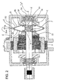
- the present invention refers to an electronically controlled, electric synchronous motor of the permanent-magnet type, in which the flux linkage with the stator windings is reduced as the rotation speed increases through a controlled extraction of the rotor from the respective stator in the axial direction.
- Such motor shall also be capable of being manufactured with the use of readily available materials, tools and techniques, and - further to being easily and conveniently practicable - shall be such as to be able to ensure reliable performance results.
- an electric permanent-magnet motor according to the present invention comprises:
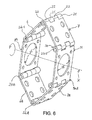
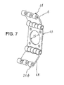
- a first bridging member which is comprised of two rigid plates 6, 7 as connected with each other by a first hinge 8 hinged on to a pin 24; the first one 6 of said rigid plates is connected with an end portion 68 thereof to a side portion of said first hinge 8 and, with the opposite end portion 69 thereof, to a second hinge 9, which is linked with an element thereof to a side of said rotor; the second one 7 of said rigid plates is connected with an end portion 78 thereof to the second side portion of said first hinge 8 and, with the opposite end portion 70 thereof, it is connected to a third hinge 10, which is linked in a firmly joined manner with the other element or side portion thereof to said rotating shaft in a firmly joined manner.
- said two rigid plates 6 and 7 and, more generally, said first bridging member are provided in an arrangement that is symmetrical relative to a plane Y extending orthogonally to said axis X.
- the force urging the rotor to displace out of and away from the stator depends on the centrifugal force that acts on said rigid plates 6, 7, 6A, 7A and urges them to move closer to each other, while urging the same rotor into such motion.
- centrifugal force depends on the square value of the rotating speed, it ensues that, even under a modest increase in the rotating speed, such centrifugal force increases in a much quicker manner, and this of course causes the force extracting the rotor from the stator to increase in a similarly quick manner
- the combined effect of said two decreasing and increasing patterns of said mutually opposed forces i.e. the rapidly decreasing force attracting the rotor into the stator and the rapidly increasing force that tends to pull the rotor out of the stator in the opposite direction, is such that the same rotor is urged in the extraction direction with a combined force resulting from said two mutually opposed forces changing in a different manner in diverging directions, which increases in a very quick manner.
- shock-damping means can be embodied in a number of different manners; anyway, with reference to Figures 9 and 10 , these means are shown to be embodied in the form of elastic tabs 40, 41, which are applied on to the outer portion of the respective plates 7 and 7A, wherein both of them are oriented towards said annular support member 37.
- tabs must also be sized and applied so as to make sure that, when the rotor rotates at a low speed, the end portions 42 and 43 thereof remain at a distance from said annular support member 37 or in a position, in which they just skim the latter (cf. Figure 9 ).
- such elastic tabs are so sized and applied as to make sure that, when the rotating speed of the rotor increases and said rigid plates move closer to each other, as this has been explained afore, said end portions 42 and 43 of the respective elastic tabs 40, 41 come to oppose the final displacement of the rotor towards and against said annular support member 37, wherein they however do this not by opposing such resistance as to definitely block such displacement, but just a resistance that will brake the rotor moving in the described manner, thereby attaining the desired ultimate result of preventing the same rotor from violently bumping against the annular support member, as set forth above (cf. Figure 10 ).
- tabs must be sized and applied so that, when the rotor rotates at a low speed, the end portions 42 and 43 thereof will reduce the pressure exerted upon or move simply away from said annular support member 37.
- shock-damping means as described above, as well as all other similar means that shall be explained further on in this description, are not provided in view of creating an elastic force tending to urge the rotor again into the stator when the rotating speed thereof decreases, as this is on the contrary described in the afore-cited document EP 1 432 101 ; as a matter of fact, no indication is given in said document that would allude to the fact that the rotor is provided with permanent magnets.
- the spring provided coaxially to the rotating shaft has the sole duty to perform in view of urging the rotor into moving back into the stator when the same rotor slows down.
- said shock-damping means i.e. said elastic tabs in the exemplarily described embodiment, are normally free, i.e. not pre-loaded or biased, in a state that is on the contrary impossible to contemplate in the case of the coaxial spring in the above-cited document, in which, in the case that said spring is not pre-loaded, i.e. biased, the rotor would not be able to be urged fully back into the stator.
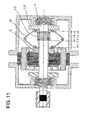
- shock-damping means can further be embodied in the form of a suitable coil spring 45 provided coaxially to and wound round the rotating shaft, as well as arranged between said rigid plates.
- This coaxial spring 45 does not extend all over the length allowed by said plates 6, 7 (and, of course, also by said plates 6A, 7A).
- said spring when in its resting state said spring shall have a length LA, as shown in Figure 11 , which is shorter than the distance LB between said boundary hinges 9 and 10, or between the hinges 9A and 10A, as the case may be, when the rotor rotates at a sufficiently low speed, i.e. when said plates are "open", i.e. moved away from each other.
- the above-mentioned spring 45 may also be freely inserted on the shaft 4, i.e. in a condition in which the respective end portions are not restrained, in consideration of the fact that, each time that it has to come into working, the position of the same spring is automatically ensured by the pushing effect of the rotor and said first fastening plate 23 towards and against said annular support member 37.
- said shock-damping means is provided in the form of an annular elastic member, which is applied to or fitted on said annular support member 37 with an end portion 60 thereof, while, on the other end portion 61 thereof, it is provided with a ring-shaped, flexible and elastic rim 62 extending towards said rigid plates 7, 7A.
- said ring-shaped rim 62 is provided in a bellows-like form, i.e. it is folded and curved so as to allow for a greater damping effect when said plates 7 and 7A are shifted towards said annular support member 37 owing to the centrifugal force that acts thereupon at the higher rotating speeds of the rotor, as this is best shown in Figure 14 .
- shock-absorbing means may be embodied in a number of further different manners, as long as they are anyway provided so as to be able to become solely active in the final phase of the axial outward displacement of the rotor, and by no way in advance thereto, and as long as they are not provided so as to perform any function or take anyway part in the backward or return displacement of the rotor towards and into the stator as the rotating speed thereof decreases.
Landscapes
- Engineering & Computer Science (AREA)
- Power Engineering (AREA)
- Connection Of Motors, Electrical Generators, Mechanical Devices, And The Like (AREA)
- Reciprocating, Oscillating Or Vibrating Motors (AREA)
Applications Claiming Priority (1)
| Application Number | Priority Date | Filing Date | Title |
|---|---|---|---|
| ITPN2008A000090A IT1392226B1 (it) | 2008-12-15 | 2008-12-15 | "motore elettrico a magneti permanenti" |
Publications (2)
| Publication Number | Publication Date |
|---|---|
| EP2197090A1 true EP2197090A1 (fr) | 2010-06-16 |
| EP2197090B1 EP2197090B1 (fr) | 2017-07-19 |
Family
ID=40873405
Family Applications (1)
| Application Number | Title | Priority Date | Filing Date |
|---|---|---|---|
| EP09177269.9A Not-in-force EP2197090B1 (fr) | 2008-12-15 | 2009-11-26 | Moteur électrique à aimant permanent |
Country Status (2)
| Country | Link |
|---|---|
| EP (1) | EP2197090B1 (fr) |
| IT (1) | IT1392226B1 (fr) |
Cited By (8)
| Publication number | Priority date | Publication date | Assignee | Title |
|---|---|---|---|---|
| CN102170211A (zh) * | 2011-04-22 | 2011-08-31 | 徐州工业职业技术学院 | 可变励磁永磁同步电动机 |
| ITPN20110006A1 (it) * | 2011-02-03 | 2012-08-04 | Nidec Sole Motor Corp S R L | Motore elettrico a magneti permanenti con rotore perfezionato |
| WO2014099549A1 (fr) * | 2012-12-19 | 2014-06-26 | Nidec Motor Corporation | Bride de modification de fréquence pour moteur électrique |
| CN106026584A (zh) * | 2016-06-15 | 2016-10-12 | 燕胜 | 永磁同步电动机转子 |
| CN108718122A (zh) * | 2018-06-06 | 2018-10-30 | 林峭 | 一种兼顾高速和低速性能的电机 |
| CN112491196A (zh) * | 2020-11-20 | 2021-03-12 | 无锡南洋职业技术学院 | 一种新能源汽车变功率电机 |
| DE102020114856B3 (de) | 2020-06-04 | 2021-09-23 | Schaeffler Technologies AG & Co. KG | Elektrische Radialflussmaschine und Antriebsstrang |
| EP4283844A1 (fr) * | 2022-05-18 | 2023-11-29 | Hamilton Sundstrand Corporation | Systèmes de générateur à aimant permanent |
Citations (6)
| Publication number | Priority date | Publication date | Assignee | Title |
|---|---|---|---|---|
| US1039197A (en) * | 1909-11-03 | 1912-09-24 | Charles H Roth | Variable-speed electric generator. |
| GB733975A (en) * | 1952-10-01 | 1955-07-20 | Bendix Aviat Corp | Improvements in or relating to alternators |
| DE1488273A1 (de) * | 1964-05-26 | 1969-08-14 | Garrett Corp | Wechselstromgenerator |
| EP0304974A1 (fr) | 1987-08-10 | 1989-03-01 | Karel Holden | Alternateur |
| EP1432101A1 (fr) | 2002-12-20 | 2004-06-23 | Tai-Her Yang | Machine électrique avec une structure pour déplacer le rotor axialement grâce aux forces centrifuges |
| US20060097604A1 (en) | 2004-11-05 | 2006-05-11 | Taku Adaniya | Electric motor and motor-driven compressor |
-
2008
- 2008-12-15 IT ITPN2008A000090A patent/IT1392226B1/it active
-
2009
- 2009-11-26 EP EP09177269.9A patent/EP2197090B1/fr not_active Not-in-force
Patent Citations (6)
| Publication number | Priority date | Publication date | Assignee | Title |
|---|---|---|---|---|
| US1039197A (en) * | 1909-11-03 | 1912-09-24 | Charles H Roth | Variable-speed electric generator. |
| GB733975A (en) * | 1952-10-01 | 1955-07-20 | Bendix Aviat Corp | Improvements in or relating to alternators |
| DE1488273A1 (de) * | 1964-05-26 | 1969-08-14 | Garrett Corp | Wechselstromgenerator |
| EP0304974A1 (fr) | 1987-08-10 | 1989-03-01 | Karel Holden | Alternateur |
| EP1432101A1 (fr) | 2002-12-20 | 2004-06-23 | Tai-Her Yang | Machine électrique avec une structure pour déplacer le rotor axialement grâce aux forces centrifuges |
| US20060097604A1 (en) | 2004-11-05 | 2006-05-11 | Taku Adaniya | Electric motor and motor-driven compressor |
Cited By (11)
| Publication number | Priority date | Publication date | Assignee | Title |
|---|---|---|---|---|
| ITPN20110006A1 (it) * | 2011-02-03 | 2012-08-04 | Nidec Sole Motor Corp S R L | Motore elettrico a magneti permanenti con rotore perfezionato |
| CN102170211A (zh) * | 2011-04-22 | 2011-08-31 | 徐州工业职业技术学院 | 可变励磁永磁同步电动机 |
| WO2014099549A1 (fr) * | 2012-12-19 | 2014-06-26 | Nidec Motor Corporation | Bride de modification de fréquence pour moteur électrique |
| US9726252B2 (en) | 2012-12-19 | 2017-08-08 | Nidec Motor Corporation | Frequency altering brace for an electric motor |
| CN106026584A (zh) * | 2016-06-15 | 2016-10-12 | 燕胜 | 永磁同步电动机转子 |
| CN106026584B (zh) * | 2016-06-15 | 2018-04-17 | 徐州市柯瑞斯电机制造有限公司 | 永磁同步电动机转子 |
| CN108718122A (zh) * | 2018-06-06 | 2018-10-30 | 林峭 | 一种兼顾高速和低速性能的电机 |
| DE102020114856B3 (de) | 2020-06-04 | 2021-09-23 | Schaeffler Technologies AG & Co. KG | Elektrische Radialflussmaschine und Antriebsstrang |
| CN112491196A (zh) * | 2020-11-20 | 2021-03-12 | 无锡南洋职业技术学院 | 一种新能源汽车变功率电机 |
| EP4283844A1 (fr) * | 2022-05-18 | 2023-11-29 | Hamilton Sundstrand Corporation | Systèmes de générateur à aimant permanent |
| US12009702B2 (en) | 2022-05-18 | 2024-06-11 | Hamilton Sundstrand Corporation | Permanent magnet generator systems |
Also Published As
| Publication number | Publication date |
|---|---|
| ITPN20080090A1 (it) | 2010-06-16 |
| IT1392226B1 (it) | 2012-02-22 |
| EP2197090B1 (fr) | 2017-07-19 |
Similar Documents
| Publication | Publication Date | Title |
|---|---|---|
| EP2197090B1 (fr) | Moteur électrique à aimant permanent | |
| EP2494684B1 (fr) | Moteur reconfigurable pouvant passer d'un fonctionnement à induction à un fonctionnement synchrone | |
| US7948132B2 (en) | Axial gap-type electric motor | |
| WO2016072379A1 (fr) | Rotor pour moteur, et moteur | |
| US8536750B2 (en) | Electric motor with axially movable rotor assembly | |
| CN102124635A (zh) | 用于旋转电动机械的内部转子及其组装方法 | |
| EP1653595A1 (fr) | Moteur-generateur et vehicule electrique comprenant ce moteur-generateur | |
| CN115668718A (zh) | 电机、用于电机的移位装置及用于机动车辆的动力系 | |
| CN109302044B (zh) | 一种可调双离合机构的永磁联轴器 | |
| CN115606079A (zh) | 轴流式电机以及用于轴流式电机的移位装置 | |
| CN102124634A (zh) | 用于旋转电动机械的包括带沟槽的轴的内部转子 | |
| US11218039B2 (en) | Electric motor with switchover elements in the magnetic circuit | |
| US6691744B1 (en) | Actuator and thread brake comprising an actuator | |
| CN115461970A (zh) | 电动径流式机器和动力系 | |
| CN209627201U (zh) | 延迟型磁力耦合器 | |
| JP4604565B2 (ja) | 回転子、およびこれを備えた回転電機 | |
| JP4807119B2 (ja) | 回転電機 | |
| US20010001477A1 (en) | Actively controlled valve for a piston compressor | |
| EP2235812B1 (fr) | Moteur synchrone à aimant permanent amélioré | |
| JP2007259531A5 (fr) | ||
| EP1553681B1 (fr) | Dispositif de couplage entre un rotor de moteur synchrone à aimants permanents et un organe de travail | |
| JP2020188587A (ja) | 電動機用ロータ、及び電動機 | |
| CN109921602B (zh) | 磁力耦合器延迟启动方法及延迟型磁力耦合器 | |
| KR102549738B1 (ko) | 자기기어용 폴피스 및 내측로터 제조방법 | |
| EP3826155A1 (fr) | Moteur électrique |
Legal Events
| Date | Code | Title | Description |
|---|---|---|---|
| PUAI | Public reference made under article 153(3) epc to a published international application that has entered the european phase |
Free format text: ORIGINAL CODE: 0009012 |
|
| AK | Designated contracting states |
Kind code of ref document: A1 Designated state(s): AT BE BG CH CY CZ DE DK EE ES FI FR GB GR HR HU IE IS IT LI LT LU LV MC MK MT NL NO PL PT RO SE SI SK SM TR |
|
| AX | Request for extension of the european patent |
Extension state: AL BA RS |
|
| 17P | Request for examination filed |
Effective date: 20100720 |
|
| RAP1 | Party data changed (applicant data changed or rights of an application transferred) |
Owner name: NIDEC SOLE MOTOR CORPORATION S.R.L. |
|
| 17Q | First examination report despatched |
Effective date: 20161128 |
|
| GRAP | Despatch of communication of intention to grant a patent |
Free format text: ORIGINAL CODE: EPIDOSNIGR1 |
|
| RIC1 | Information provided on ipc code assigned before grant |
Ipc: H02K 21/02 20060101ALI20170320BHEP Ipc: H02K 7/12 20060101AFI20170320BHEP |
|
| INTG | Intention to grant announced |
Effective date: 20170421 |
|
| GRAS | Grant fee paid |
Free format text: ORIGINAL CODE: EPIDOSNIGR3 |
|
| GRAA | (expected) grant |
Free format text: ORIGINAL CODE: 0009210 |
|
| AK | Designated contracting states |
Kind code of ref document: B1 Designated state(s): AT BE BG CH CY CZ DE DK EE ES FI FR GB GR HR HU IE IS IT LI LT LU LV MC MK MT NL NO PL PT RO SE SI SK SM TR |
|
| REG | Reference to a national code |
Ref country code: GB Ref legal event code: FG4D |
|
| REG | Reference to a national code |
Ref country code: CH Ref legal event code: EP |
|
| REG | Reference to a national code |
Ref country code: IE Ref legal event code: FG4D |
|
| REG | Reference to a national code |
Ref country code: AT Ref legal event code: REF Ref document number: 911283 Country of ref document: AT Kind code of ref document: T Effective date: 20170815 |
|
| REG | Reference to a national code |
Ref country code: DE Ref legal event code: R096 Ref document number: 602009047180 Country of ref document: DE |
|
| REG | Reference to a national code |
Ref country code: NL Ref legal event code: MP Effective date: 20170719 |
|
| REG | Reference to a national code |
Ref country code: LT Ref legal event code: MG4D |
|
| REG | Reference to a national code |
Ref country code: AT Ref legal event code: MK05 Ref document number: 911283 Country of ref document: AT Kind code of ref document: T Effective date: 20170719 |
|
| PG25 | Lapsed in a contracting state [announced via postgrant information from national office to epo] |
Ref country code: AT Free format text: LAPSE BECAUSE OF FAILURE TO SUBMIT A TRANSLATION OF THE DESCRIPTION OR TO PAY THE FEE WITHIN THE PRESCRIBED TIME-LIMIT Effective date: 20170719 Ref country code: SE Free format text: LAPSE BECAUSE OF FAILURE TO SUBMIT A TRANSLATION OF THE DESCRIPTION OR TO PAY THE FEE WITHIN THE PRESCRIBED TIME-LIMIT Effective date: 20170719 Ref country code: NO Free format text: LAPSE BECAUSE OF FAILURE TO SUBMIT A TRANSLATION OF THE DESCRIPTION OR TO PAY THE FEE WITHIN THE PRESCRIBED TIME-LIMIT Effective date: 20171019 Ref country code: HR Free format text: LAPSE BECAUSE OF FAILURE TO SUBMIT A TRANSLATION OF THE DESCRIPTION OR TO PAY THE FEE WITHIN THE PRESCRIBED TIME-LIMIT Effective date: 20170719 Ref country code: NL Free format text: LAPSE BECAUSE OF FAILURE TO SUBMIT A TRANSLATION OF THE DESCRIPTION OR TO PAY THE FEE WITHIN THE PRESCRIBED TIME-LIMIT Effective date: 20170719 Ref country code: FI Free format text: LAPSE BECAUSE OF FAILURE TO SUBMIT A TRANSLATION OF THE DESCRIPTION OR TO PAY THE FEE WITHIN THE PRESCRIBED TIME-LIMIT Effective date: 20170719 Ref country code: LT Free format text: LAPSE BECAUSE OF FAILURE TO SUBMIT A TRANSLATION OF THE DESCRIPTION OR TO PAY THE FEE WITHIN THE PRESCRIBED TIME-LIMIT Effective date: 20170719 |
|
| PG25 | Lapsed in a contracting state [announced via postgrant information from national office to epo] |
Ref country code: IS Free format text: LAPSE BECAUSE OF FAILURE TO SUBMIT A TRANSLATION OF THE DESCRIPTION OR TO PAY THE FEE WITHIN THE PRESCRIBED TIME-LIMIT Effective date: 20171119 Ref country code: BG Free format text: LAPSE BECAUSE OF FAILURE TO SUBMIT A TRANSLATION OF THE DESCRIPTION OR TO PAY THE FEE WITHIN THE PRESCRIBED TIME-LIMIT Effective date: 20171019 Ref country code: PL Free format text: LAPSE BECAUSE OF FAILURE TO SUBMIT A TRANSLATION OF THE DESCRIPTION OR TO PAY THE FEE WITHIN THE PRESCRIBED TIME-LIMIT Effective date: 20170719 Ref country code: ES Free format text: LAPSE BECAUSE OF FAILURE TO SUBMIT A TRANSLATION OF THE DESCRIPTION OR TO PAY THE FEE WITHIN THE PRESCRIBED TIME-LIMIT Effective date: 20170719 Ref country code: GR Free format text: LAPSE BECAUSE OF FAILURE TO SUBMIT A TRANSLATION OF THE DESCRIPTION OR TO PAY THE FEE WITHIN THE PRESCRIBED TIME-LIMIT Effective date: 20171020 Ref country code: LV Free format text: LAPSE BECAUSE OF FAILURE TO SUBMIT A TRANSLATION OF THE DESCRIPTION OR TO PAY THE FEE WITHIN THE PRESCRIBED TIME-LIMIT Effective date: 20170719 |
|
| REG | Reference to a national code |
Ref country code: DE Ref legal event code: R097 Ref document number: 602009047180 Country of ref document: DE |
|
| PG25 | Lapsed in a contracting state [announced via postgrant information from national office to epo] |
Ref country code: RO Free format text: LAPSE BECAUSE OF FAILURE TO SUBMIT A TRANSLATION OF THE DESCRIPTION OR TO PAY THE FEE WITHIN THE PRESCRIBED TIME-LIMIT Effective date: 20170719 Ref country code: DK Free format text: LAPSE BECAUSE OF FAILURE TO SUBMIT A TRANSLATION OF THE DESCRIPTION OR TO PAY THE FEE WITHIN THE PRESCRIBED TIME-LIMIT Effective date: 20170719 Ref country code: CZ Free format text: LAPSE BECAUSE OF FAILURE TO SUBMIT A TRANSLATION OF THE DESCRIPTION OR TO PAY THE FEE WITHIN THE PRESCRIBED TIME-LIMIT Effective date: 20170719 |
|
| PLBE | No opposition filed within time limit |
Free format text: ORIGINAL CODE: 0009261 |
|
| STAA | Information on the status of an ep patent application or granted ep patent |
Free format text: STATUS: NO OPPOSITION FILED WITHIN TIME LIMIT |
|
| PG25 | Lapsed in a contracting state [announced via postgrant information from national office to epo] |
Ref country code: EE Free format text: LAPSE BECAUSE OF FAILURE TO SUBMIT A TRANSLATION OF THE DESCRIPTION OR TO PAY THE FEE WITHIN THE PRESCRIBED TIME-LIMIT Effective date: 20170719 Ref country code: SK Free format text: LAPSE BECAUSE OF FAILURE TO SUBMIT A TRANSLATION OF THE DESCRIPTION OR TO PAY THE FEE WITHIN THE PRESCRIBED TIME-LIMIT Effective date: 20170719 Ref country code: SM Free format text: LAPSE BECAUSE OF FAILURE TO SUBMIT A TRANSLATION OF THE DESCRIPTION OR TO PAY THE FEE WITHIN THE PRESCRIBED TIME-LIMIT Effective date: 20170719 |
|
| 26N | No opposition filed |
Effective date: 20180420 |
|
| PG25 | Lapsed in a contracting state [announced via postgrant information from national office to epo] |
Ref country code: MC Free format text: LAPSE BECAUSE OF FAILURE TO SUBMIT A TRANSLATION OF THE DESCRIPTION OR TO PAY THE FEE WITHIN THE PRESCRIBED TIME-LIMIT Effective date: 20170719 |
|
| GBPC | Gb: european patent ceased through non-payment of renewal fee |
Effective date: 20171126 |
|
| PG25 | Lapsed in a contracting state [announced via postgrant information from national office to epo] |
Ref country code: CH Free format text: LAPSE BECAUSE OF NON-PAYMENT OF DUE FEES Effective date: 20171130 Ref country code: LI Free format text: LAPSE BECAUSE OF NON-PAYMENT OF DUE FEES Effective date: 20171130 |
|
| PG25 | Lapsed in a contracting state [announced via postgrant information from national office to epo] |
Ref country code: LU Free format text: LAPSE BECAUSE OF NON-PAYMENT OF DUE FEES Effective date: 20171126 Ref country code: SI Free format text: LAPSE BECAUSE OF FAILURE TO SUBMIT A TRANSLATION OF THE DESCRIPTION OR TO PAY THE FEE WITHIN THE PRESCRIBED TIME-LIMIT Effective date: 20170719 |
|
| REG | Reference to a national code |
Ref country code: FR Ref legal event code: ST Effective date: 20180731 Ref country code: BE Ref legal event code: MM Effective date: 20171130 |
|
| REG | Reference to a national code |
Ref country code: IE Ref legal event code: MM4A |
|
| PG25 | Lapsed in a contracting state [announced via postgrant information from national office to epo] |
Ref country code: MT Free format text: LAPSE BECAUSE OF NON-PAYMENT OF DUE FEES Effective date: 20171126 |
|
| PG25 | Lapsed in a contracting state [announced via postgrant information from national office to epo] |
Ref country code: IE Free format text: LAPSE BECAUSE OF NON-PAYMENT OF DUE FEES Effective date: 20171126 Ref country code: FR Free format text: LAPSE BECAUSE OF NON-PAYMENT OF DUE FEES Effective date: 20171130 |
|
| PG25 | Lapsed in a contracting state [announced via postgrant information from national office to epo] |
Ref country code: BE Free format text: LAPSE BECAUSE OF NON-PAYMENT OF DUE FEES Effective date: 20171130 Ref country code: GB Free format text: LAPSE BECAUSE OF NON-PAYMENT OF DUE FEES Effective date: 20171126 |
|
| PG25 | Lapsed in a contracting state [announced via postgrant information from national office to epo] |
Ref country code: HU Free format text: LAPSE BECAUSE OF FAILURE TO SUBMIT A TRANSLATION OF THE DESCRIPTION OR TO PAY THE FEE WITHIN THE PRESCRIBED TIME-LIMIT; INVALID AB INITIO Effective date: 20091126 |
|
| PG25 | Lapsed in a contracting state [announced via postgrant information from national office to epo] |
Ref country code: CY Free format text: LAPSE BECAUSE OF NON-PAYMENT OF DUE FEES Effective date: 20170719 |
|
| PG25 | Lapsed in a contracting state [announced via postgrant information from national office to epo] |
Ref country code: MK Free format text: LAPSE BECAUSE OF FAILURE TO SUBMIT A TRANSLATION OF THE DESCRIPTION OR TO PAY THE FEE WITHIN THE PRESCRIBED TIME-LIMIT Effective date: 20170719 |
|
| PGFP | Annual fee paid to national office [announced via postgrant information from national office to epo] |
Ref country code: DE Payment date: 20191121 Year of fee payment: 11 |
|
| PG25 | Lapsed in a contracting state [announced via postgrant information from national office to epo] |
Ref country code: TR Free format text: LAPSE BECAUSE OF FAILURE TO SUBMIT A TRANSLATION OF THE DESCRIPTION OR TO PAY THE FEE WITHIN THE PRESCRIBED TIME-LIMIT Effective date: 20170719 |
|
| PG25 | Lapsed in a contracting state [announced via postgrant information from national office to epo] |
Ref country code: PT Free format text: LAPSE BECAUSE OF FAILURE TO SUBMIT A TRANSLATION OF THE DESCRIPTION OR TO PAY THE FEE WITHIN THE PRESCRIBED TIME-LIMIT Effective date: 20170719 |
|
| REG | Reference to a national code |
Ref country code: DE Ref legal event code: R119 Ref document number: 602009047180 Country of ref document: DE |
|
| PG25 | Lapsed in a contracting state [announced via postgrant information from national office to epo] |
Ref country code: DE Free format text: LAPSE BECAUSE OF NON-PAYMENT OF DUE FEES Effective date: 20210601 |
|
| PGFP | Annual fee paid to national office [announced via postgrant information from national office to epo] |
Ref country code: IT Payment date: 20211118 Year of fee payment: 13 |
|
| PG25 | Lapsed in a contracting state [announced via postgrant information from national office to epo] |
Ref country code: IT Free format text: LAPSE BECAUSE OF NON-PAYMENT OF DUE FEES Effective date: 20221126 |