EP2196742B1 - Chauffe-eau pour une utilisation dans un avion - Google Patents
Chauffe-eau pour une utilisation dans un avion Download PDFInfo
- Publication number
- EP2196742B1 EP2196742B1 EP09405211.5A EP09405211A EP2196742B1 EP 2196742 B1 EP2196742 B1 EP 2196742B1 EP 09405211 A EP09405211 A EP 09405211A EP 2196742 B1 EP2196742 B1 EP 2196742B1
- Authority
- EP
- European Patent Office
- Prior art keywords
- section
- tank
- bottom face
- denotes
- reference numeral
- Prior art date
- Legal status (The legal status is an assumption and is not a legal conclusion. Google has not performed a legal analysis and makes no representation as to the accuracy of the status listed.)
- Active
Links
- XLYOFNOQVPJJNP-UHFFFAOYSA-N water Substances O XLYOFNOQVPJJNP-UHFFFAOYSA-N 0.000 title claims description 135
- 239000007788 liquid Substances 0.000 claims description 24
- 239000000758 substrate Substances 0.000 claims description 20
- 238000010438 heat treatment Methods 0.000 claims description 9
- 230000000149 penetrating effect Effects 0.000 claims description 2
- 238000010586 diagram Methods 0.000 description 7
- 238000009835 boiling Methods 0.000 description 2
- 230000007935 neutral effect Effects 0.000 description 2
- 125000006850 spacer group Chemical group 0.000 description 2
- 229920000049 Carbon (fiber) Polymers 0.000 description 1
- 230000036760 body temperature Effects 0.000 description 1
- 239000004917 carbon fiber Substances 0.000 description 1
- 230000007797 corrosion Effects 0.000 description 1
- 238000005260 corrosion Methods 0.000 description 1
- 230000007423 decrease Effects 0.000 description 1
- 230000001419 dependent effect Effects 0.000 description 1
- 239000008236 heating water Substances 0.000 description 1
- 239000000463 material Substances 0.000 description 1
- VNWKTOKETHGBQD-UHFFFAOYSA-N methane Chemical compound C VNWKTOKETHGBQD-UHFFFAOYSA-N 0.000 description 1
- 230000003647 oxidation Effects 0.000 description 1
- 238000007254 oxidation reaction Methods 0.000 description 1
- 238000011084 recovery Methods 0.000 description 1
- 239000007787 solid Substances 0.000 description 1
Images


Classifications
-
- F—MECHANICAL ENGINEERING; LIGHTING; HEATING; WEAPONS; BLASTING
- F24—HEATING; RANGES; VENTILATING
- F24H—FLUID HEATERS, e.g. WATER OR AIR HEATERS, HAVING HEAT-GENERATING MEANS, e.g. HEAT PUMPS, IN GENERAL
- F24H1/00—Water heaters, e.g. boilers, continuous-flow heaters or water-storage heaters
- F24H1/18—Water-storage heaters
- F24H1/20—Water-storage heaters with immersed heating elements, e.g. electric elements or furnace tubes
- F24H1/201—Water-storage heaters with immersed heating elements, e.g. electric elements or furnace tubes using electric energy supply
- F24H1/202—Water-storage heaters with immersed heating elements, e.g. electric elements or furnace tubes using electric energy supply with resistances
-
- F—MECHANICAL ENGINEERING; LIGHTING; HEATING; WEAPONS; BLASTING
- F24—HEATING; RANGES; VENTILATING
- F24H—FLUID HEATERS, e.g. WATER OR AIR HEATERS, HAVING HEAT-GENERATING MEANS, e.g. HEAT PUMPS, IN GENERAL
- F24H15/00—Control of fluid heaters
- F24H15/10—Control of fluid heaters characterised by the purpose of the control
- F24H15/128—Preventing overheating
- F24H15/132—Preventing the operation of water heaters with low water levels, e.g. dry-firing
-
- F—MECHANICAL ENGINEERING; LIGHTING; HEATING; WEAPONS; BLASTING
- F24—HEATING; RANGES; VENTILATING
- F24H—FLUID HEATERS, e.g. WATER OR AIR HEATERS, HAVING HEAT-GENERATING MEANS, e.g. HEAT PUMPS, IN GENERAL
- F24H15/00—Control of fluid heaters
- F24H15/20—Control of fluid heaters characterised by control inputs
- F24H15/212—Temperature of the water
- F24H15/223—Temperature of the water in the water storage tank
-
- F—MECHANICAL ENGINEERING; LIGHTING; HEATING; WEAPONS; BLASTING
- F24—HEATING; RANGES; VENTILATING
- F24H—FLUID HEATERS, e.g. WATER OR AIR HEATERS, HAVING HEAT-GENERATING MEANS, e.g. HEAT PUMPS, IN GENERAL
- F24H15/00—Control of fluid heaters
- F24H15/20—Control of fluid heaters characterised by control inputs
- F24H15/242—Pressure
-
- F—MECHANICAL ENGINEERING; LIGHTING; HEATING; WEAPONS; BLASTING
- F24—HEATING; RANGES; VENTILATING
- F24H—FLUID HEATERS, e.g. WATER OR AIR HEATERS, HAVING HEAT-GENERATING MEANS, e.g. HEAT PUMPS, IN GENERAL
- F24H15/00—Control of fluid heaters
- F24H15/30—Control of fluid heaters characterised by control outputs; characterised by the components to be controlled
- F24H15/355—Control of heat-generating means in heaters
- F24H15/37—Control of heat-generating means in heaters of electric heaters
-
- F—MECHANICAL ENGINEERING; LIGHTING; HEATING; WEAPONS; BLASTING
- F24—HEATING; RANGES; VENTILATING
- F24H—FLUID HEATERS, e.g. WATER OR AIR HEATERS, HAVING HEAT-GENERATING MEANS, e.g. HEAT PUMPS, IN GENERAL
- F24H15/00—Control of fluid heaters
- F24H15/30—Control of fluid heaters characterised by control outputs; characterised by the components to be controlled
- F24H15/395—Information to users, e.g. alarms
-
- F—MECHANICAL ENGINEERING; LIGHTING; HEATING; WEAPONS; BLASTING
- F24—HEATING; RANGES; VENTILATING
- F24H—FLUID HEATERS, e.g. WATER OR AIR HEATERS, HAVING HEAT-GENERATING MEANS, e.g. HEAT PUMPS, IN GENERAL
- F24H9/00—Details
- F24H9/0005—Details for water heaters
- F24H9/001—Guiding means
- F24H9/0015—Guiding means in water channels
-
- F—MECHANICAL ENGINEERING; LIGHTING; HEATING; WEAPONS; BLASTING
- F24—HEATING; RANGES; VENTILATING
- F24H—FLUID HEATERS, e.g. WATER OR AIR HEATERS, HAVING HEAT-GENERATING MEANS, e.g. HEAT PUMPS, IN GENERAL
- F24H9/00—Details
- F24H9/20—Arrangement or mounting of control or safety devices
- F24H9/2007—Arrangement or mounting of control or safety devices for water heaters
- F24H9/2014—Arrangement or mounting of control or safety devices for water heaters using electrical energy supply
- F24H9/2021—Storage heaters
-
- H—ELECTRICITY
- H05—ELECTRIC TECHNIQUES NOT OTHERWISE PROVIDED FOR
- H05B—ELECTRIC HEATING; ELECTRIC LIGHT SOURCES NOT OTHERWISE PROVIDED FOR; CIRCUIT ARRANGEMENTS FOR ELECTRIC LIGHT SOURCES, IN GENERAL
- H05B3/00—Ohmic-resistance heating
- H05B3/40—Heating elements having the shape of rods or tubes
- H05B3/42—Heating elements having the shape of rods or tubes non-flexible
- H05B3/44—Heating elements having the shape of rods or tubes non-flexible heating conductor arranged within rods or tubes of insulating material
-
- F—MECHANICAL ENGINEERING; LIGHTING; HEATING; WEAPONS; BLASTING
- F24—HEATING; RANGES; VENTILATING
- F24H—FLUID HEATERS, e.g. WATER OR AIR HEATERS, HAVING HEAT-GENERATING MEANS, e.g. HEAT PUMPS, IN GENERAL
- F24H2250/00—Electrical heat generating means
- F24H2250/02—Resistances
Definitions
- the present invention relates to an aircraft use water heater that operates by an aircraft power source of an AC variable frequency provided in an aircraft, that is small, light-weight, safe, and low power consumption, and that can provide an efficient heating.
- Fig. 15 illustrates a schematic structure of an aircraft use water heater of a conventional example. As shown in Fig. 15 , cold water flowing from the lower part of a water heater is upwardly moved and heated along the periphery of a plurality of heaters provided in a tank section to thereby provide hot water through an opening at the upper part of the tank section.
- An aircraft water heater is also disclosed in the following Patent Document.
- Patent Document 1 Japanese Unexamined Patent Application No. 2002-46696 Patent document JP2007240117 discloses an electric hot water heater according to the preamble of claim 1.
- the aircraft use water heater comprises a tank section for heating liquid stored therein and a controlling section for controlling the heating of the liquid by an aircraft power source.
- the aircraft use water heater includes: an inflow inlet formed in a bottom face of the tank section through which the liquid flows into the tank section; a baffle plate that is provided at an upper part of the inflow inlet and that prevents the liquid from moving in a straight manner; a helical coil-type heater in the tank section, the helical coil-type heater has a helical axis provided in a direction parallel to the bottom face of the tank section; and a liquid outlet formed in an upper part of a wall face of the tank section.
- Liquid flowing from the inflow inlet to the tank section collides against the baffle plate to flow in a different direction parallel to the bottom face of the tank section and moves to the lower part of the helical coil-type heater and then is moved upwardly, while being heated, in the vicinity of a helical coil section of the helical coil-type heater and the heated liquid is caused to flow through the liquid outlet.
- the baffle plate is provided in a direction dislocated by a predetermined angle from a direction along which the baffle plate is orthogonal to a helical axis of the helical coil-type heater, liquid flowing from the baffle plate in a direction parallel to the bottom face collides against a helical coil section at a lower part of the helical coil-type heater to flow in a different direction and is moved upwardly, while being heated, in the vicinity of the helical coil section.
- the bottom face of the controlling section has an aircraft power source connector and a liquid inlet
- the aircraft power source connector is connected to a power source control substrate in the controlling section
- the liquid inlet of the bottom face of the controlling section is connected to the inflow inlet of the bottom face of the tank section via an inner pipe penetrating an interior of the controlling section.
- a radiating control element connected to the power source control substrate of the controlling section is provided at a back face of the bottom face of the tank section, and heat generated from the radiating control element is used to heat the liquid via the bottom face of the tank section.
- a pressure sensor, a thermistor sensor, and a temperature fuse as a safety apparatus are provided in the tank section and are connected to the power source control substrate in the controlling section via a connecting section provided at a back face of the bottom face of the tank section.
- a side face of the tank section has, as a safety apparatus, a release valve, a thermostat, and a light-emitting diode indicator indicating ON or OFF of a power source.
- the baffle plate prevents the warm water heated by the heater in the tank from being mixed with cold water entering the tank and water is gradually moved upward from the lower part of the tank.
- an increased amount of warm water can be supplied for a fixed time and at a fixed temperature.
- a part of components is attached to the tank bottom face and the control substrate is integrated to the controlling section at the lower part of the tank.
- the tank can have a smaller size and a higher capacitance, thus achieving a 1/4-reduced boiling time.
- Fig. 1 is a front view illustrating an aircraft use water heater of an illustrative embodiment of the present invention.
- the reference numeral 1 denotes a water heater
- the reference numeral 10 denotes a tank section
- the reference numeral 11 denotes a water outlet
- the reference numeral 20 denotes a controlling section
- the reference numeral 23 denotes a tank bottom face
- the reference numeral 26 denotes a connecting section
- the reference numeral 102 denotes a release valve
- the reference numeral 103 denotes a thermostat
- the reference numeral 109 denotes a light-emitting diode indicator
- the reference numeral 201 denotes a power source connector.
- the water heater 1 is composed of the tank section 10 and the controlling section 20.
- the tank section 10 is connected to the controlling section 20 via the connecting section 26.
- the tank section 10 includes the water outlet 11, the release valve 102, and the thermostat 103. Water to be heated is stored at the upper part of the tank bottom face 23 and heated warm water is taken out through the water outlet 11.
- the release valve 102 is released when the pressure in the tank increases.
- the thermostat 103 is a safety apparatus that detects an increase in the temperature of the apparatus to stop heating.
- the controlling section 20 controls the heating of the water stored in the tank section 10.
- the lower part of the controlling section 20 has the power source connector 201 that is connected to an aircraft power source of AC variable frequencies from 360Hz to 800Hz.
- a side wall of the controlling section 20 has the light-emitting diode indicator 109 that indicates the ON or OFF of the power source.
- Fig. 2 is a side view illustrating the aircraft use water heater of an illustrative embodiment of the present invention.
- the reference numeral 1 denotes a water heater
- the reference numeral 10 denotes a tank section
- the reference numeral 11 denotes a water outlet
- the reference numeral 20 denotes a controlling section
- the reference numeral 21 denotes a water inlet
- the reference numeral 26 denotes a connecting section
- the reference numeral 102 denotes a release valve
- the reference numeral 109 denotes a light-emitting diode indicator
- the reference numeral 201 denotes a power source connector.
- the water inlet 21 provided at the lower part of the controlling section 20 of the water heater 1 and the water outlet 11 provided at the upper part of the side wall of the tank section 10 are connected to a piping and the power source connector 201 is connected to a power source.
- the water inlet 21 receives water supplied from the fuselage and the power source connector 201 receives single-phase AC (nominal AC115V, 360Hz to 800Hz).
- the light-emitting diode indicator 109 is lit to indicate that the power source is ON and heated warm water is taken out through the water outlet 11 of the tank section 10.
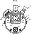
- Fig. 3 is a bottom view illustrating the aircraft use water heater of the illustrative embodiment of the present invention.
- the reference numeral 10 denotes a tank section
- the reference numeral 11 denotes a water outlet
- the reference numeral 20 denotes a controlling section
- the reference numeral 21 denotes a water inlet
- the reference numeral 26 denotes a connecting section
- the reference numeral 102 denotes a release valve
- the reference numeral 103 denotes a thermostat
- the reference numeral 201 denotes a power source connector
- the reference numeral 202 denotes an AC power source terminal
- the reference numeral 203 denotes an AC neutral point terminal
- the reference numeral 204 denotes a chassis ground terminal
- the reference numeral 205 denotes a fixed ground terminal.
- the tank section 10 is connected to the controlling section 20 via the connecting section 26. Water flowing from the water inlet 21 at the bottom section of the controlling section 20 is heated in the tank section 10 and heated warm water is taken out through the water outlet 11 of the tank section 10.
- the bottom section of the controlling section 20 has the power source connector 201.
- the AC power source terminal 202 and the AC neutral point terminal 203 of the power source connector 201 are connected to an aircraft power source of 115V and a variable frequency from 360Hz to 800Hz.
- the chassis ground terminal 204 and the fixed ground terminal 205 are connected to the tank section 10 and are grounded.
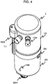
- Fig. 4 is a perspective view illustrating the aircraft use water heater of the illustrative embodiment of the present invention.
- the reference numeral 1 denotes a water heater
- the reference numeral 10 denotes a tank section
- the reference numeral 11 denotes a water outlet
- the reference numeral 20 denotes a controlling section
- the reference numeral 201 denotes a power source connector
- the reference numeral 26 denotes a connecting section
- the reference numeral 102 denotes a release valve
- the reference numeral 103 denotes a thermostat
- the reference numeral 109 denotes a light-emitting diode indicator.
- Fig. 5 is an exploded perspective view illustrating the tank section of the aircraft use water heater of the illustrative embodiment of the present invention.
- the reference numeral 10 denotes a tank section
- the reference numeral 21 denotes a water inlet
- the reference numeral 22 denotes an inner pipe
- the reference numeral 23 denotes a tank bottom face
- the reference numeral 24 denotes an inflow inlet
- the reference numeral 25 denotes a baffle plate
- the reference numeral 101 denotes a helical coil heater
- the reference numeral 104 denotes a temperature fuse.
- the bottom face 23 of the tank section 10 has the helical coil heater 101, the temperature fuse 104, and the baffle plate 25.
- the temperature fuse 104 is a safety apparatus that senses an overtemperature to prevent boil-dry.
- the helical coil heater 101 uses a sheath tube made of austenite-base stainless NAR-AH-1 having superior high temperature corrosion resistance, oxidation resistance, and machinability to improve the durability. By having the coil-like shape to increase the surface area, the watt density is reduced.
- the helical coil heater 101 is provided so that the helical axis is in parallel with the bottom face 23 of the tank section 10.
- the water inlet 21 provided at the lower part of the controlling section and the inflow inlet 24 provided in the tank bottom face 23 of the tank section 10 are connected to each other via an inner pipe extending so as to penetrate the interior of the controlling section.
- the water flowing in the water inlet 21 is sent through the inner pipe 22 and flows from the inflow inlet 24 of the tank bottom face 23 to the interior of the tank section 10.
- the tank bottom face 23 is provided so that the baffle plate 25 covers the inflow inlet 24 of the tank bottom face 23.
- the water flowing from the inflow inlet 24 collides against the baffle plate 25 and then water flows in a different direction to flow along the tank bottom face 23 in the direction of the helical coil heater 101 and then is moved upwardly, while being heated, in the vicinity of the helical coil section of the helical coil heater 101.
- Fig. 6 is a cross-sectional view illustrating the tank section of the aircraft use water heater of the illustrative embodiment of the present invention.
- the reference numeral 22 denotes an inner pipe
- the reference numeral 23 denotes a tank bottom face
- the reference numeral 24 denotes an inflow inlet
- the reference numeral 25 denotes a baffle plate
- the reference numeral 101 denotes a helical coil heater
- the reference numeral 104 denotes a temperature fuse.
- the bottom face 23 of the tank section 10 has the helical coil heater 101, the temperature fuse 104, and the baffle plate 25.
- the temperature fuse 104 is a safety apparatus that senses an overtemperature to prevent boil-dry.
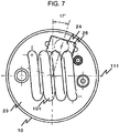
- Fig. 7 is an exploded top view illustrating the tank section of the aircraft use water heater of the illustrative embodiment of the present invention.
- the reference numeral 10 denotes a tank section
- the reference numeral 23 denotes a tank bottom face
- the reference numeral 24 denotes an inflow inlet
- the reference numeral 25 denotes a baffle plate
- the reference numeral 101 denotes a helical coil heater
- the reference numeral 111 denotes a helical axis.
- the baffle plate 25 is provided in a direction dislocated by a predetermined angle (17 degrees in the drawing) from the direction along which the baffle plate 25 is orthogonal to the helical axis 111 of the helical coil heater 101.
- the water flowing from the baffle plate 25 moves along the tank bottom face 23 in the direction of the helical coil heater 101 and collides against the heated helical coil section of the helical coil heater 101 and is collected, without passing the helical coil heater 101, in the vicinity of the helical coil section and is moved upwardly, while being heated, in the vicinity of the helical coil section.
- water is heated efficiently and can be quickly heated with low power consumption.
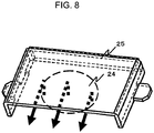
- Fig. 8 is a perspective view illustrating a baffle plate provided in the tank section of the aircraft use water heater of the illustrative embodiment of the present invention.
- the reference numeral 24 denotes an inflow inlet
- the reference numeral 25 denotes a baffle plate
- the arrows show the flow of water.
- the baffle plate 25 is composed of: an upper face plate against which water flowing from the inflow inlet 24 to the tank section collides; side face plates covering side faces other than that in the direction along which water flows out; and a connecting section for connecting the baffle plate 25 to the tank bottom face.
- Fig. 9 is a layout diagram illustrating control elements of the tank bottom face of the aircraft use water heater of the illustrative embodiment of the present invention.
- the reference numeral 10 denotes a tank section
- the reference numeral 11 denotes a water outlet
- the reference numeral 21 denotes a water inlet
- the reference numeral 23 denotes a tank bottom face
- the reference numeral 26 denotes a connecting section
- the reference numeral 101 denotes a helical coil heater
- the reference numeral 102 denotes a release valve
- the reference numeral 103 denotes a thermostat
- the reference numeral 104 denotes a temperature fuse
- the reference numeral 106 denotes a thermistor
- the reference numeral 107 denotes a pressure sensor (switch)
- the reference numeral 108 denotes a solid state relay (SSR)
- the reference numeral 205 denotes a bonding connecting section.
- the center of the back face of the tank bottom face 23 has the SSR 108. Heat generated by the SSR 108 is transmitted through the tank bottom face 23 into the tank section 10 and the baffle plate 25 is used to efficiently heat the water flowing along the tank bottom face 23.
- the release valve 102, the thermostat 103, the temperature fuse 104, the thermistor sensor 106, the pressure sensor (switch) 107 or the like are safety apparatuses that protect the operation of an aircraft use water heater.
- the release valve 102 senses a high pressure in the tank section 10.
- the pressure sensor (switch) 107 senses the water pressure in the tank section 10 to prevent boil-dry.
- the thermistor sensor 106 senses an overtemperature to prevent boil-dry.
- the thermostat 103 prevents an overtemperature and boil-dry.
- the temperature fuse 104 senses an overtemperature to prevent boil-dry.
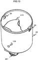
- Fig. 10 is an exploded perspective view illustrating a controlling section of the aircraft use water heater of the illustrative embodiment of the present invention.
- the reference numeral 20 denotes a controlling section
- the reference numeral 201 denotes a power source connector
- the reference numeral 26 denotes a connecting section
- the reference numeral 109 denotes a light-emitting diode indicator
- the reference numeral 210 denotes a control substrate cover.
- the control substrate cover 210 covers the power source control substrate in the controlling section 20.
- the upper space of the control substrate cover 210 of the controlling section 20 has the connecting parts to the respective safety apparatuses provided at the back face of the tank bottom face 23 of the tank section 10.
- Fig. 11 is a perspective view illustrating a power source control substrate provided in a controlling section of the aircraft use water heater of the illustrative embodiment of the present invention.
- the reference numeral 206 denotes a power source control substrate (PCB)
- the reference numeral 207 denotes a spacer
- the reference numeral 211 denotes a circuit element.
- the power source control substrates 206 are provided at an interval therebetween by the spacers 207 and are connected to various circuit elements 211.
- the power source control substrate 206 is provided at the lower part of the control substrate cover 210 and is connected to the respective safety apparatuses provided at the upper part of the control substrate cover 210.
- Fig. 12 is a connecting diagram of the aircraft use water heater of the illustrative embodiment of the present invention.
- the reference numeral 10 denotes a tank section
- the reference numeral 101 denotes a helical coil heater
- the reference numeral 103 denotes a thermostat
- the reference numeral 104 denotes a temperature fuse
- the reference numeral 106 denotes a thermistor sensor
- the reference numeral 107 denotes a pressure sensor (switch)
- the reference numeral 108 denotes a SSR
- the reference numeral 109 denotes a light-emitting diode indicator
- the reference numeral 110 denotes a current fuse
- the reference numeral 201 denotes a power source connector
- the reference numeral 206 denotes a power source control substrate (PCB)
- the reference numeral 209 denotes an IC comparator.
- the power source connector 201 receives single-phase AC (nominal AC115V, 360Hz to 800Hz).
- the pressure sensor (switch) 107 By allowing the pressure sensor (switch) 107 to sense the water pressure in the tank to turn ON the SSR 108, power is supplied to the IC comparator 209.
- the thermistor sensor 106 and the IC comparator 209 are used to sense the temperature of the water in the tank and, when the water temperature is lower than the set value, the SSR 108 is turned ON to supply power to the helical coil heater 101 to start the heating. When the water temperature reaches the set value, the SSR 108 is turned OFF and the heating is stopped.
- Fig. 13 is a table of performances and characteristics for the aircraft use water heater of the illustrative embodiment of the present invention.
- the dry weight in the case of the conventional example is 1.81kg
- the dry weight of the present invention is 1.18kg, showing a 35%-reduction.
- the outer diameter of the conventional example is 102mm and the outer diameter of the present invention is 90mm.
- the height of the conventional example is 305mm and the height of the present invention is 244mm, showing a 45%-reduction.
- the present invention can handle variable frequencies from 360Hz to 800Hz.
- the power consumption and current consumption while the conventional example requires 420W and 3.61A, the present invention requires 700W and 6.1A.
- the initial boiling time could be significantly improved from 9 minutes of the conventional example to 2 minutes and 15 seconds.
- the recovery time was significantly improved from 1 minute and 50 seconds of the conventional example to 1 minute.
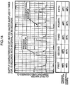
- Fig. 14 is a reference diagram illustrating the hot water temperature characteristic repeatedly obtained by the aircraft use water heater of the illustrative embodiment of the present invention.
- Fig. 14 shows a change in the temperature characteristic when warm water is supplied 5 times for 15 seconds with an interval of 60 seconds.
- the first warm water is 46 degrees C and the second warm water is 45 degrees C but the fourth warm water is 40 degrees C and the fifth warm water is 37 degrees C, showing a significant decline of the temperature of the water and causing cold water having a temperature around a body temperature to be discharged through the warm water outlet.
- the aircraft use water heater of the present invention on the other hand can provide the first warm water of 48 degrees C, the second warm water of 51 degrees C and the fifth warm water of 49 degrees C, thus continuously supplying warm water of a high temperature.
- the water heater of the present invention can be used as a hot-water supply apparatus in a lavatory of an aircraft and can be combined with a warm water mixer to supply warm water of various temperatures. Furthermore, the small and efficient structure of the water heater of the present invention also can be widely used in a wide range in addition to aircraft use devices.
Landscapes
- Engineering & Computer Science (AREA)
- Physics & Mathematics (AREA)
- Thermal Sciences (AREA)
- Chemical & Material Sciences (AREA)
- Combustion & Propulsion (AREA)
- Mechanical Engineering (AREA)
- General Engineering & Computer Science (AREA)
- Heat-Pump Type And Storage Water Heaters (AREA)
- Instantaneous Water Boilers, Portable Hot-Water Supply Apparatuses, And Control Of Portable Hot-Water Supply Apparatuses (AREA)
Claims (5)
- Chauffe-eau (1) pour une utilisation dans un avion comprenant une section de réservoir (10) pour chauffer du liquide qui y est stocké et une section de commande (20) pour commander le chauffage du liquide par une source de puissance de l'avion,
dans lequel le chauffe-eau (1) pour une utilisation dans un avion comprend:un orifice d'entrée (24) formé dans une face de fond (23) de la section de réservoir (10) à travers lequel le liquide s'écoule dans la section de réservoir (10) ;une plaque de déflecteur (25) qui est prévue à une partie supérieure de l'orifice d'entrée (24) et qui empêche le liquide de se mouvoir en ligne droite;un dispositif de chauffage du type à serpentin hélicoïdal (101) dans la section de réservoir (10), le dispositif de chauffage du type à serpentin hélicoïdal (101) présente un axe d'hélice (111) prévu dans une direction parallèle à la face de fond (23) de la section de réservoir (10); etun orifice de sortie de liquide (11) formé dans une partie supérieure d'une face de paroi de la section de réservoir (10),le liquide s'écoulant de l'orifice d'entrée (24) vers la section de réservoir (10) frappe la plaque de déflecteur (25) afin de s'écouler dans une direction différente parallèle à la face de fond (23) de la section de réservoir (10) et se déplace vers la partie inférieure du dispositif de chauffage du type à serpentin hélicoïdal (101) et est ensuite déplacé vers le haut, tout en étant chauffé, à proximité de la section de serpentin hélicoïdal du dispositif de chauffage du type à serpentin hélicoïdal (101) et le liquide chauffé est amené à s'écouler à travers l'orifice de sortie de liquide (11),caractérisé en ce que la plaque de déflecteur (25) est prévue dans une direction déviée d'un angle prédéterminé d'une direction le long de laquelle la plaque de déflecteur (25) est orthogonale à un axe d'hélice (111) du dispositif de chauffage du type à serpentin hélicoïdal (101), le liquide s'écoulant de la plaque de déflecteur (25) dans une direction parallèle à la face de fond (23) frappe une section de serpentin hélicoïdal à une partie inférieure du dispositif de chauffage du type à serpentin hélicoïdal (101) pour s'écouler dans une direction différente et est déplacé vers le haut, tout en étant chauffé, à proximité de la section de serpentin hélicoïdal, eten ce que la plaque de déflecteur (25) est composée d'une plaque de face supérieure contre laquelle l'eau s'écoulant de l'orifice d'entrée (24) vers la section de réservoir (10) frappe des plaques de face latérale couvrant des faces latérales autres que celle dans la direction le long de laquelle l'eau s'écoule vers l'extérieur et d'une section de connexion pour connecter la plaque de déflecteur (25) à la face de fond (23) du réservoir (10). - Chauffe-eau (1) pour une utilisation dans un avion selon la revendication 1,
dans lequel la face de fond (23) de la section de commande (20) comporte un connecteur (201) à une source de puissance de l'avion et un orifice d'entrée de liquide (21), le connecteur (201) à une source de puissance de l'avion est connecté à un substrat de commande de source de puissance (206) dans la section de commande (20), l'orifice d'entrée de liquide (21) de la face de fond (23) de la section de commande (20) est connecté à l'orifice d'entrée (24) de la face de fond (23) de la section de réservoir (10) via un tuyau intérieur (22) pénétrant à l'intérieur de la section de commande (20). - Chauffe-eau (1) pour une utilisation dans un avion selon la revendication 2,
dans lequel il est prévu un élément de commande de rayonnement connecté au substrat de commande de source de puissance (206) de la section de commande (20) à une face arrière de la face de fond (23) de la section de réservoir (10), la face de fond (23) du réservoir (10) est utilisée comme puits de chaleur, et la chaleur générée par l'élément de commande de rayonnement est utilisée pour chauffer le liquide via la face de fond (23) de la section de réservoir (10). - Chauffe-eau (1) pour une utilisation dans un avion selon la revendication 3,
dans lequel il est prévu un capteur de pression (107), un capteur à thermistor (106), et un fusible thermique (104) comme appareil de sécurité dans la section de réservoir (10) et ils sont connectés au substrat de commande de source de puissance (206) dans la section de commande (20) via une section de connexion prévue sur une face arrière de la face de fond (23) de la section de réservoir (10). - Chauffe-eau (1) pour une utilisation dans un avion selon la revendication 4,
dans lequel une face latérale de la section de réservoir (10) comporte, comme appareil de sécurité, une soupape de détente (102), un thermostat (103), et un indicateur à diode électroluminescente (109) indiquant ON [Marche] ou OFF [Arrêt] d'une source de puissance.
Applications Claiming Priority (1)
| Application Number | Priority Date | Filing Date | Title |
|---|---|---|---|
| JP2008315946A JP5283495B2 (ja) | 2008-12-11 | 2008-12-11 | 航空機搭載用給湯装置 |
Publications (3)
| Publication Number | Publication Date |
|---|---|
| EP2196742A2 EP2196742A2 (fr) | 2010-06-16 |
| EP2196742A3 EP2196742A3 (fr) | 2016-04-13 |
| EP2196742B1 true EP2196742B1 (fr) | 2018-08-08 |
Family
ID=41626497
Family Applications (1)
| Application Number | Title | Priority Date | Filing Date |
|---|---|---|---|
| EP09405211.5A Active EP2196742B1 (fr) | 2008-12-11 | 2009-12-03 | Chauffe-eau pour une utilisation dans un avion |
Country Status (3)
| Country | Link |
|---|---|
| US (1) | US8270822B2 (fr) |
| EP (1) | EP2196742B1 (fr) |
| JP (1) | JP5283495B2 (fr) |
Families Citing this family (6)
| Publication number | Priority date | Publication date | Assignee | Title |
|---|---|---|---|---|
| JP5283495B2 (ja) * | 2008-12-11 | 2013-09-04 | 株式会社ジャムコ | 航空機搭載用給湯装置 |
| WO2017015593A1 (fr) | 2015-07-22 | 2017-01-26 | National Machine Group | Réservoir d'eau chaude |
| EP3315872B1 (fr) * | 2016-10-27 | 2021-03-10 | Stiebel Eltron GmbH & Co. KG | Ballon d'eau chaude et flasque chauffant pour un ballon d'eau chaude |
| US10583928B2 (en) | 2017-04-10 | 2020-03-10 | B/E Aerospace, Inc. | Inline heater controller |
| US11903101B2 (en) * | 2019-12-13 | 2024-02-13 | Goodrich Corporation | Internal heating trace assembly |
| KR102665868B1 (ko) * | 2021-06-24 | 2024-05-14 | 김노을 | 유체 및 열교환 영역을 감싸는 이온수 배치 구조의 가열 디바이스 |
Family Cites Families (15)
| Publication number | Priority date | Publication date | Assignee | Title |
|---|---|---|---|---|
| US2322502A (en) * | 1940-03-06 | 1943-06-22 | Harry A Beckstrom | Water heater |
| BE788523A (nl) * | 1971-09-08 | 1973-03-07 | Peteri Henri B | Heet-waterapparaat |
| US3868991A (en) * | 1972-09-14 | 1975-03-04 | Avm Corp | Valve assembly |
| CH621619A5 (en) * | 1977-09-29 | 1981-02-13 | Cipag Sa | Storage unit for heat-transfer liquid, particularly water |
| US4173872A (en) * | 1978-02-01 | 1979-11-13 | Energy Utilization Systems, Inc. | Water heater apparatus |
| JPH0263105U (fr) * | 1988-10-26 | 1990-05-11 | ||
| US5179914A (en) * | 1991-09-30 | 1993-01-19 | Mor-Flo Industries, Inc. | Forced draft water heater with an improved tank structure and a method for making water heaters |
| JP3698593B2 (ja) * | 1999-07-15 | 2005-09-21 | サンポット株式会社 | 電気温水器 |
| JP4374751B2 (ja) | 2000-08-03 | 2009-12-02 | 株式会社島津製作所 | 航空機用の熱利用装置 |
| GB0304114D0 (en) * | 2003-02-22 | 2003-03-26 | Bwe Ltd | Continuous extrusion apparatus |
| DE10334527A1 (de) * | 2003-07-29 | 2005-02-17 | Pav Patentverwertung Kg | Heißgetränkezubereiter, insbesondere Kaffeemaschine |
| ATE463990T1 (de) * | 2005-09-19 | 2010-04-15 | Koninkl Philips Electronics Nv | Vorrichtung zur herstellung eines getränks mit wasserkocher |
| JP4714048B2 (ja) * | 2006-03-10 | 2011-06-29 | 株式会社 エスト | 冷水生成装置ならびにそれを用いた冷温水サーバー |
| JP4898250B2 (ja) * | 2006-03-10 | 2012-03-14 | 株式会社 エスト | 冷水生成装置ならびにそれを用いた冷温水サーバー |
| JP5283495B2 (ja) * | 2008-12-11 | 2013-09-04 | 株式会社ジャムコ | 航空機搭載用給湯装置 |
-
2008
- 2008-12-11 JP JP2008315946A patent/JP5283495B2/ja active Active
-
2009
- 2009-12-03 EP EP09405211.5A patent/EP2196742B1/fr active Active
- 2009-12-08 US US12/633,356 patent/US8270822B2/en active Active
Also Published As
| Publication number | Publication date |
|---|---|
| EP2196742A3 (fr) | 2016-04-13 |
| JP2010139165A (ja) | 2010-06-24 |
| JP5283495B2 (ja) | 2013-09-04 |
| US8270822B2 (en) | 2012-09-18 |
| US20100150535A1 (en) | 2010-06-17 |
| EP2196742A2 (fr) | 2010-06-16 |
Similar Documents
| Publication | Publication Date | Title |
|---|---|---|
| EP2196742B1 (fr) | Chauffe-eau pour une utilisation dans un avion | |
| EP2515728B1 (fr) | Chauffe-eau instantanés | |
| JP6096112B2 (ja) | 水を加熱し、蒸気を生成するデバイス | |
| EP2432355B1 (fr) | Dispositifs de chauffage | |
| EP1724530A1 (fr) | Système et procédé pour la drainage d'eau d'un four à vapeur | |
| US20080017724A1 (en) | Water heating distribution system | |
| RU2287915C2 (ru) | Микроволновая печь с кофеваркой и способ управления ею | |
| US9702544B2 (en) | Boiler for domestic appliances and water heating systems with steam production for home and industrial use | |
| CN105865033A (zh) | 一种开水器的水温控制方法 | |
| JP6913824B2 (ja) | 浄水機能を有する多機能食品調理器 | |
| CN204617901U (zh) | 电水壶 | |
| US20090047007A1 (en) | Instantaneous water heater with a heating tube | |
| WO2010106348A2 (fr) | Dispositifs de chauffage | |
| CN107091526B (zh) | 即时沸腾热水系统 | |
| CN109497832A (zh) | 饮水机以及饮水机的控制方法 | |
| KR200389074Y1 (ko) | 가스레인지의 폐열을 이용한 온수장치 | |
| CN101639284A (zh) | 一种电加热器 | |
| CN107157321B (zh) | 电水壶 | |
| CN110089930A (zh) | 一种立体即热环流蒸汽分离器及系统 | |
| CN202408453U (zh) | 一种快速降压的压力锅 | |
| EP0309199A2 (fr) | Distributeur d'eau chaude à ébullition | |
| EP0127344A2 (fr) | Procédé et appareil pour le chauffage d'un liquide | |
| CN202262843U (zh) | 一种用于家用电器的水加热装置 | |
| JP2003314892A5 (fr) | ||
| CN108065807A (zh) | 一种食物料理机 |
Legal Events
| Date | Code | Title | Description |
|---|---|---|---|
| PUAI | Public reference made under article 153(3) epc to a published international application that has entered the european phase |
Free format text: ORIGINAL CODE: 0009012 |
|
| AK | Designated contracting states |
Kind code of ref document: A2 Designated state(s): AT BE BG CH CY CZ DE DK EE ES FI FR GB GR HR HU IE IS IT LI LT LU LV MC MK MT NL NO PL PT RO SE SI SK SM TR |
|
| AX | Request for extension of the european patent |
Extension state: AL BA RS |
|
| PUAL | Search report despatched |
Free format text: ORIGINAL CODE: 0009013 |
|
| AK | Designated contracting states |
Kind code of ref document: A3 Designated state(s): AT BE BG CH CY CZ DE DK EE ES FI FR GB GR HR HU IE IS IT LI LT LU LV MC MK MT NL NO PL PT RO SE SI SK SM TR |
|
| AX | Request for extension of the european patent |
Extension state: AL BA RS |
|
| RIC1 | Information provided on ipc code assigned before grant |
Ipc: F24H 9/00 20060101ALI20160308BHEP Ipc: F24H 1/20 20060101AFI20160308BHEP Ipc: F24H 9/20 20060101ALI20160308BHEP |
|
| 17P | Request for examination filed |
Effective date: 20160627 |
|
| RBV | Designated contracting states (corrected) |
Designated state(s): AT BE BG CH CY CZ DE DK EE ES FI FR GB GR HR HU IE IS IT LI LT LU LV MC MK MT NL NO PL PT RO SE SI SK SM TR |
|
| GRAP | Despatch of communication of intention to grant a patent |
Free format text: ORIGINAL CODE: EPIDOSNIGR1 |
|
| STAA | Information on the status of an ep patent application or granted ep patent |
Free format text: STATUS: GRANT OF PATENT IS INTENDED |
|
| RIC1 | Information provided on ipc code assigned before grant |
Ipc: H05B 3/44 20060101ALI20180118BHEP Ipc: F24H 1/20 20060101AFI20180118BHEP Ipc: F24H 9/00 20060101ALI20180118BHEP Ipc: F24H 9/20 20060101ALI20180118BHEP |
|
| INTG | Intention to grant announced |
Effective date: 20180220 |
|
| GRAS | Grant fee paid |
Free format text: ORIGINAL CODE: EPIDOSNIGR3 |
|
| GRAA | (expected) grant |
Free format text: ORIGINAL CODE: 0009210 |
|
| STAA | Information on the status of an ep patent application or granted ep patent |
Free format text: STATUS: THE PATENT HAS BEEN GRANTED |
|
| AK | Designated contracting states |
Kind code of ref document: B1 Designated state(s): AT BE BG CH CY CZ DE DK EE ES FI FR GB GR HR HU IE IS IT LI LT LU LV MC MK MT NL NO PL PT RO SE SI SK SM TR |
|
| REG | Reference to a national code |
Ref country code: GB Ref legal event code: FG4D |
|
| REG | Reference to a national code |
Ref country code: CH Ref legal event code: EP Ref country code: AT Ref legal event code: REF Ref document number: 1027450 Country of ref document: AT Kind code of ref document: T Effective date: 20180815 |
|
| REG | Reference to a national code |
Ref country code: IE Ref legal event code: FG4D |
|
| REG | Reference to a national code |
Ref country code: DE Ref legal event code: R096 Ref document number: 602009053696 Country of ref document: DE |
|
| REG | Reference to a national code |
Ref country code: NL Ref legal event code: MP Effective date: 20180808 |
|
| REG | Reference to a national code |
Ref country code: LT Ref legal event code: MG4D |
|
| REG | Reference to a national code |
Ref country code: AT Ref legal event code: MK05 Ref document number: 1027450 Country of ref document: AT Kind code of ref document: T Effective date: 20180808 |
|
| PG25 | Lapsed in a contracting state [announced via postgrant information from national office to epo] |
Ref country code: BG Free format text: LAPSE BECAUSE OF FAILURE TO SUBMIT A TRANSLATION OF THE DESCRIPTION OR TO PAY THE FEE WITHIN THE PRESCRIBED TIME-LIMIT Effective date: 20181108 Ref country code: GR Free format text: LAPSE BECAUSE OF FAILURE TO SUBMIT A TRANSLATION OF THE DESCRIPTION OR TO PAY THE FEE WITHIN THE PRESCRIBED TIME-LIMIT Effective date: 20181109 Ref country code: IS Free format text: LAPSE BECAUSE OF FAILURE TO SUBMIT A TRANSLATION OF THE DESCRIPTION OR TO PAY THE FEE WITHIN THE PRESCRIBED TIME-LIMIT Effective date: 20181208 Ref country code: NO Free format text: LAPSE BECAUSE OF FAILURE TO SUBMIT A TRANSLATION OF THE DESCRIPTION OR TO PAY THE FEE WITHIN THE PRESCRIBED TIME-LIMIT Effective date: 20181108 Ref country code: AT Free format text: LAPSE BECAUSE OF FAILURE TO SUBMIT A TRANSLATION OF THE DESCRIPTION OR TO PAY THE FEE WITHIN THE PRESCRIBED TIME-LIMIT Effective date: 20180808 Ref country code: FI Free format text: LAPSE BECAUSE OF FAILURE TO SUBMIT A TRANSLATION OF THE DESCRIPTION OR TO PAY THE FEE WITHIN THE PRESCRIBED TIME-LIMIT Effective date: 20180808 Ref country code: LT Free format text: LAPSE BECAUSE OF FAILURE TO SUBMIT A TRANSLATION OF THE DESCRIPTION OR TO PAY THE FEE WITHIN THE PRESCRIBED TIME-LIMIT Effective date: 20180808 Ref country code: NL Free format text: LAPSE BECAUSE OF FAILURE TO SUBMIT A TRANSLATION OF THE DESCRIPTION OR TO PAY THE FEE WITHIN THE PRESCRIBED TIME-LIMIT Effective date: 20180808 Ref country code: SE Free format text: LAPSE BECAUSE OF FAILURE TO SUBMIT A TRANSLATION OF THE DESCRIPTION OR TO PAY THE FEE WITHIN THE PRESCRIBED TIME-LIMIT Effective date: 20180808 Ref country code: PL Free format text: LAPSE BECAUSE OF FAILURE TO SUBMIT A TRANSLATION OF THE DESCRIPTION OR TO PAY THE FEE WITHIN THE PRESCRIBED TIME-LIMIT Effective date: 20180808 |
|
| PG25 | Lapsed in a contracting state [announced via postgrant information from national office to epo] |
Ref country code: LV Free format text: LAPSE BECAUSE OF FAILURE TO SUBMIT A TRANSLATION OF THE DESCRIPTION OR TO PAY THE FEE WITHIN THE PRESCRIBED TIME-LIMIT Effective date: 20180808 Ref country code: HR Free format text: LAPSE BECAUSE OF FAILURE TO SUBMIT A TRANSLATION OF THE DESCRIPTION OR TO PAY THE FEE WITHIN THE PRESCRIBED TIME-LIMIT Effective date: 20180808 Ref country code: ES Free format text: LAPSE BECAUSE OF FAILURE TO SUBMIT A TRANSLATION OF THE DESCRIPTION OR TO PAY THE FEE WITHIN THE PRESCRIBED TIME-LIMIT Effective date: 20180808 |
|
| PG25 | Lapsed in a contracting state [announced via postgrant information from national office to epo] |
Ref country code: CZ Free format text: LAPSE BECAUSE OF FAILURE TO SUBMIT A TRANSLATION OF THE DESCRIPTION OR TO PAY THE FEE WITHIN THE PRESCRIBED TIME-LIMIT Effective date: 20180808 Ref country code: RO Free format text: LAPSE BECAUSE OF FAILURE TO SUBMIT A TRANSLATION OF THE DESCRIPTION OR TO PAY THE FEE WITHIN THE PRESCRIBED TIME-LIMIT Effective date: 20180808 Ref country code: IT Free format text: LAPSE BECAUSE OF FAILURE TO SUBMIT A TRANSLATION OF THE DESCRIPTION OR TO PAY THE FEE WITHIN THE PRESCRIBED TIME-LIMIT Effective date: 20180808 Ref country code: EE Free format text: LAPSE BECAUSE OF FAILURE TO SUBMIT A TRANSLATION OF THE DESCRIPTION OR TO PAY THE FEE WITHIN THE PRESCRIBED TIME-LIMIT Effective date: 20180808 |
|
| REG | Reference to a national code |
Ref country code: DE Ref legal event code: R097 Ref document number: 602009053696 Country of ref document: DE |
|
| PG25 | Lapsed in a contracting state [announced via postgrant information from national office to epo] |
Ref country code: SK Free format text: LAPSE BECAUSE OF FAILURE TO SUBMIT A TRANSLATION OF THE DESCRIPTION OR TO PAY THE FEE WITHIN THE PRESCRIBED TIME-LIMIT Effective date: 20180808 Ref country code: DK Free format text: LAPSE BECAUSE OF FAILURE TO SUBMIT A TRANSLATION OF THE DESCRIPTION OR TO PAY THE FEE WITHIN THE PRESCRIBED TIME-LIMIT Effective date: 20180808 Ref country code: SM Free format text: LAPSE BECAUSE OF FAILURE TO SUBMIT A TRANSLATION OF THE DESCRIPTION OR TO PAY THE FEE WITHIN THE PRESCRIBED TIME-LIMIT Effective date: 20180808 |
|
| PLBE | No opposition filed within time limit |
Free format text: ORIGINAL CODE: 0009261 |
|
| STAA | Information on the status of an ep patent application or granted ep patent |
Free format text: STATUS: NO OPPOSITION FILED WITHIN TIME LIMIT |
|
| 26N | No opposition filed |
Effective date: 20190509 |
|
| REG | Reference to a national code |
Ref country code: CH Ref legal event code: PL |
|
| GBPC | Gb: european patent ceased through non-payment of renewal fee |
Effective date: 20181203 |
|
| PG25 | Lapsed in a contracting state [announced via postgrant information from national office to epo] |
Ref country code: SI Free format text: LAPSE BECAUSE OF FAILURE TO SUBMIT A TRANSLATION OF THE DESCRIPTION OR TO PAY THE FEE WITHIN THE PRESCRIBED TIME-LIMIT Effective date: 20180808 Ref country code: MC Free format text: LAPSE BECAUSE OF FAILURE TO SUBMIT A TRANSLATION OF THE DESCRIPTION OR TO PAY THE FEE WITHIN THE PRESCRIBED TIME-LIMIT Effective date: 20180808 Ref country code: LU Free format text: LAPSE BECAUSE OF NON-PAYMENT OF DUE FEES Effective date: 20181203 |
|
| REG | Reference to a national code |
Ref country code: IE Ref legal event code: MM4A |
|
| REG | Reference to a national code |
Ref country code: BE Ref legal event code: MM Effective date: 20181231 |
|
| PG25 | Lapsed in a contracting state [announced via postgrant information from national office to epo] |
Ref country code: IE Free format text: LAPSE BECAUSE OF NON-PAYMENT OF DUE FEES Effective date: 20181203 |
|
| PG25 | Lapsed in a contracting state [announced via postgrant information from national office to epo] |
Ref country code: BE Free format text: LAPSE BECAUSE OF NON-PAYMENT OF DUE FEES Effective date: 20181231 |
|
| PG25 | Lapsed in a contracting state [announced via postgrant information from national office to epo] |
Ref country code: LI Free format text: LAPSE BECAUSE OF NON-PAYMENT OF DUE FEES Effective date: 20181231 Ref country code: GB Free format text: LAPSE BECAUSE OF NON-PAYMENT OF DUE FEES Effective date: 20181203 Ref country code: CH Free format text: LAPSE BECAUSE OF NON-PAYMENT OF DUE FEES Effective date: 20181231 |
|
| PG25 | Lapsed in a contracting state [announced via postgrant information from national office to epo] |
Ref country code: MT Free format text: LAPSE BECAUSE OF NON-PAYMENT OF DUE FEES Effective date: 20181203 |
|
| PG25 | Lapsed in a contracting state [announced via postgrant information from national office to epo] |
Ref country code: TR Free format text: LAPSE BECAUSE OF FAILURE TO SUBMIT A TRANSLATION OF THE DESCRIPTION OR TO PAY THE FEE WITHIN THE PRESCRIBED TIME-LIMIT Effective date: 20180808 |
|
| PG25 | Lapsed in a contracting state [announced via postgrant information from national office to epo] |
Ref country code: PT Free format text: LAPSE BECAUSE OF FAILURE TO SUBMIT A TRANSLATION OF THE DESCRIPTION OR TO PAY THE FEE WITHIN THE PRESCRIBED TIME-LIMIT Effective date: 20180808 |
|
| PG25 | Lapsed in a contracting state [announced via postgrant information from national office to epo] |
Ref country code: MK Free format text: LAPSE BECAUSE OF NON-PAYMENT OF DUE FEES Effective date: 20180808 Ref country code: CY Free format text: LAPSE BECAUSE OF FAILURE TO SUBMIT A TRANSLATION OF THE DESCRIPTION OR TO PAY THE FEE WITHIN THE PRESCRIBED TIME-LIMIT Effective date: 20180808 Ref country code: HU Free format text: LAPSE BECAUSE OF FAILURE TO SUBMIT A TRANSLATION OF THE DESCRIPTION OR TO PAY THE FEE WITHIN THE PRESCRIBED TIME-LIMIT; INVALID AB INITIO Effective date: 20091203 |
|
| P01 | Opt-out of the competence of the unified patent court (upc) registered |
Effective date: 20230527 |
|
| PGFP | Annual fee paid to national office [announced via postgrant information from national office to epo] |
Ref country code: FR Payment date: 20231108 Year of fee payment: 15 Ref country code: DE Payment date: 20231031 Year of fee payment: 15 |