EP2196398B1 - Method for controlling a machine for handling containers - Google Patents
Method for controlling a machine for handling containers Download PDFInfo
- Publication number
- EP2196398B1 EP2196398B1 EP09173902A EP09173902A EP2196398B1 EP 2196398 B1 EP2196398 B1 EP 2196398B1 EP 09173902 A EP09173902 A EP 09173902A EP 09173902 A EP09173902 A EP 09173902A EP 2196398 B1 EP2196398 B1 EP 2196398B1
- Authority
- EP
- European Patent Office
- Prior art keywords
- machine
- turntable
- containers
- drive
- turntable drive
- Prior art date
- Legal status (The legal status is an assumption and is not a legal conclusion. Google has not performed a legal analysis and makes no representation as to the accuracy of the status listed.)
- Active
Links
- 238000000034 method Methods 0.000 title claims description 31
- 238000002372 labelling Methods 0.000 claims description 24
- 230000002950 deficient Effects 0.000 claims description 23
- 238000012545 processing Methods 0.000 claims description 14
- 230000009849 deactivation Effects 0.000 claims description 9
- 238000012423 maintenance Methods 0.000 claims description 9
- 238000012544 monitoring process Methods 0.000 claims description 9
- 238000001514 detection method Methods 0.000 claims description 5
- 238000007689 inspection Methods 0.000 claims description 2
- 238000012806 monitoring device Methods 0.000 claims description 2
- 238000011144 upstream manufacturing Methods 0.000 claims description 2
- 238000007789 sealing Methods 0.000 claims 1
- 238000004519 manufacturing process Methods 0.000 description 7
- 230000008569 process Effects 0.000 description 6
- 230000008901 benefit Effects 0.000 description 5
- 230000007547 defect Effects 0.000 description 4
- 238000010586 diagram Methods 0.000 description 3
- 230000007257 malfunction Effects 0.000 description 3
- 230000008859 change Effects 0.000 description 2
- 238000007599 discharging Methods 0.000 description 2
- 238000012546 transfer Methods 0.000 description 2
- 238000012800 visualization Methods 0.000 description 2
- 230000004913 activation Effects 0.000 description 1
- 235000013361 beverage Nutrition 0.000 description 1
- 238000010276 construction Methods 0.000 description 1
- 238000010924 continuous production Methods 0.000 description 1
- 230000001419 dependent effect Effects 0.000 description 1
- 238000011161 development Methods 0.000 description 1
- 230000018109 developmental process Effects 0.000 description 1
- 238000011143 downstream manufacturing Methods 0.000 description 1
- 230000003287 optical effect Effects 0.000 description 1
- 238000004806 packaging method and process Methods 0.000 description 1
- 238000003825 pressing Methods 0.000 description 1
- 238000012797 qualification Methods 0.000 description 1
- 230000008439 repair process Effects 0.000 description 1
- 230000004044 response Effects 0.000 description 1
- 238000000926 separation method Methods 0.000 description 1
- 230000001360 synchronised effect Effects 0.000 description 1
Images

Classifications
-
- B—PERFORMING OPERATIONS; TRANSPORTING
- B65—CONVEYING; PACKING; STORING; HANDLING THIN OR FILAMENTARY MATERIAL
- B65C—LABELLING OR TAGGING MACHINES, APPARATUS, OR PROCESSES
- B65C9/00—Details of labelling machines or apparatus
- B65C9/40—Controls; Safety devices
-
- B—PERFORMING OPERATIONS; TRANSPORTING
- B65—CONVEYING; PACKING; STORING; HANDLING THIN OR FILAMENTARY MATERIAL
- B65C—LABELLING OR TAGGING MACHINES, APPARATUS, OR PROCESSES
- B65C9/00—Details of labelling machines or apparatus
- B65C9/06—Devices for presenting articles in predetermined attitude or position at labelling station
Definitions
- the invention relates to a method for controlling a machine for treating containers, in particular a rotary machine, with the features of independent method claim 1.
- the invention further relates to a corresponding machine for treating containers with the features of independent claim 11.
- the treatment of containers such as, for example, their filling or the application of labels on containers and bottles filled with beverages is usually carried out in a continuous process by means of automatic machines.
- the labeling is done with automatic labeling machines, which usually form part of a rotary machine for container filling. When operating these machines can occur many different errors that can lead to a shutdown of the filling machine under unfavorable circumstances depending on the type of fault.
- Known rotary machines are provided with rotating plates on which the containers or bottles are and can be brought into a desired angular orientation.
- These so-called turntables each have their own turntable drive, usually in the form of an electromotive drive, which allows the individual container orientation and positioning.
- a labeling machine for containers with a turntable according to the preamble of claim 1 is known from DE 31 37 201 A1 out.
- this turntable a plurality of turntables are stored, the rotation of which is so controlled in one revolution of the turntable that the recorded by them to be labeled container with certain movement conditions arranged on the circumference of the turntable Etikettierorgane, Anbürstorgane o.
- Each turntable is coupled with its own stepper motor attached to the turntable.
- each stepping motor is connected to a control device which supplies it with control pulses as a function of the movement conditions of the turntable.
- the EP 0 717 703 B1 discloses a computer-controlled, carousel-type labeling machine, wherein each handling station for containers with a motor is provided, which is driven together with the drive motor for the carousel by a computer in order to align the container in the desired manner for the exact attachment of the labels can.
- a labeling machine with a turntable is out of the DE 31 37 201 A1 known.
- the labeling machine of the DE-Offenlegungsschrift has several turntables connected to a control unit.
- the control unit has its own switching unit for each turntable. This is to ensure that in case of a defect of a turntable only the defective turntable fails. If a turntable is defective, replacement of the defective turntable must be carried out to avoid incorrect labeling. This results in downtime of the machine.
- a module includes a camera to detect the correct fit of labels. If labels on containers are outside predefined tolerance ranges, an automatic machine stop can be effected.
- An object of the present invention is to provide a method by means of which the defect- or defect-related downtimes of a machine for treating and / or processing containers can be reduced.
- the present invention provides a method for controlling a machine for treating containers and these downstream processing and / or treatment stations.
- the machine has a plurality of respective motor-driven turntables for aligning and / or positioning of the containers.
- the motor drives of the turntable are each monitored separately, so that when an error occurs one or more of the turntable drives affected faulty turntable drives are disabled without the machine and / or the downstream stations must be turned off.
- the machine may in particular be a rotary machine, in which a plurality of turntable drives are arranged on a rotor, with the aid of which on the turntables standing containers or bottles can be rotated and positioned in the desired manner, for example, to be able to attach the labels to the respectively correct position by means of downstream labeling stations.
- the turntables are supplied with a common operating voltage and industry standard today by means of data bus control lines.
- the present invention provides for the continued operation of the machine at a detected fault in one or more rotary actuators for the turntable. Since the affected turntable drives are uniquely identifiable, they can be disabled individually and the subsequent processes can be individually adapted to it by the positions to be assigned to the disabled turntable drives are handled in an adapted manner. This can be done, for example, by switching off the affected labeling units and / or by discharging the unlabeled containers from the conveyor and possibly by returning the containers to a suitable process stage of the treatment or processing.
- each deactivated turntable drive triggers an at least partial deactivation of respectively subsequent processing and / or treatment steps of the container positions assigned to the deactivated turntable drive of the machine.
- a downstream labeling device can be temporarily deactivated at least for the container position to be assigned to the faulty turntable drive, thereby avoiding rejects due to incorrectly labeled containers which can not be rotated and positioned as required in the application of the labels can.
- Each deactivated turntable drive should initiate an at least partial deactivation of respectively subsequent monitoring steps of the bin positions associated with the deactivated turntable drive of the machine so that the entire downstream treatment and processing process of the machine can be adjusted so that, due to the slightly reduced output of treated containers, only productivity falls by a small amount. Unplanned production interruptions can be prevented in most cases this way be, so that it comes with the help of the method according to the invention to no negative influences on the maintenance and production schedule of the machine.
- the unfavorable for productivity reasons machine shutdown can be avoided by the method according to the invention in that the partial deactivation of monitoring steps is coupled with a deactivation of an automatic machine shutdown due to the at least one faulty turntable drive.
- a downstream filling device can also be temporarily deactivated at least for the container position to be assigned to the faulty turntable drive.
- a downstream device for closing the containers can be temporarily deactivated at least for the container position to be assigned to the faulty turntable drive.
- each deactivated turntable drive can be coupled with a downstream of the machine or rotary machine diverter for discharging each of the deactivated turntable drive associated containers of further subsequent processing and / or treatment steps of the machine.
- the diversion device can be coupled to a conveying device for returning the withdrawn containers into the rotary machine and / or into a preceding conveying device, so that the containers which are not labeled or treated in any other way can be returned directly to the production process, whereby the total output of the machine is only reduced by an insignificant, negligible proportion.
- the inventive method is particularly suitable for controlling a rotary machine having a circular arrangement of a plurality of each motor-driven turntables for aligning and / or positioning of the container and for controlling a Geradiquermaschine having a linear array.
- the present invention relates to a machine for processing and / or treatment of containers, which is equipped with a plurality of each motor-driven turntables for aligning and / or positioning of the containers.
- This machine may in particular be a so-called rotary machine, in which the turntables are arranged on the outer circumference of a rotor.
- the motor drives the turntable is assigned in each case a monitoring device for separate function monitoring and output of an error signal in an error occurring.
- the machine further comprises a control device for processing the error signals, for deactivating the affected faulty turntable drives and for switching off individual functions of the machine during its continued operation. Further variants and embodiments of such a machine result from the previously described variants of the method according to the invention for operating such a machine.
- the aspects and advantages discussed using the example of the method relate in the same way to the appropriate machine and all their variants.
- the basis of the present invention is the possibility of selectively setting individual drives in operation and monitoring. If one or more of the drives are deselected, their output stages or so-called power units are switched off and the drive is decoupled from the data bus with the aid of the control software. Thus, all error messages and operating states related to the deselected drives are ignored.
- the settings in the drive configuration and the monitoring function are set so that the "silence" of the affected drive leads to no warning or error.
- the unselected drives are no longer started in this case via the data bus and thus remain in the de-energized state.
- the drive itself is designed in such a way that no energization of the output stages occurs in the absence of control commands.
- the particular advantage of the function according to the invention is that in the case of a malfunction of a single drive, this is deselected and the production can be resumed immediately or continue running without interruption.
- the system can be operated with slightly reduced power.
- the affected drive can then be replaced at the next routine maintenance or during a planned production changeover or during a product change, and thus at a time-uncritical moment.
- a suitable visualization of one or more disconnected turntable drives can be provided, for example by means of a screen display in a control center.
- the visualization may already be coupled with a qualification of the detected error, in order, for example, to be able to recognize and report the type of defect so that the maintenance and repair can be accelerated.
- Fig. 1 shows a schematic structure of an embodiment of a rotary machine for processing and labeling of containers.
- Fig. 2 shows a schematic block diagram of a control of electrically operated turntable drives of the rotary machine according to Fig. 1 ,
- Fig. 3 shows on the basis of another block diagram an operating mode with deactivated turntable drive.
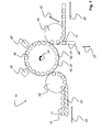
- FIG. 1 shows a typical construction of a rotary machine 10 with an inlet star 32 and an outlet star 36 and a rotating container table 34.
- a rotating Einteilschnecke 30 brings a, on a conveyor belt (not shown) incoming container flow with containers 12 in the transport direction 20 gap to the required distance to to ensure trouble-free transfer into a container-oriented recess of the inlet star 32.
- the inlet star 32 transfers the containers 12 to centering or turntable 42, which are mounted in a circular shape on the edge of the container table 34.
- the tray table 34 is rotated clockwise 24.
- the standing on the turntables 42 container 12 are moved past at least one labeling unit 26 and labeled.
- the containers 12 are rotated relative to the stationary labeling unit 26.
- each turntable 42 has an electromotive turntable drive 44. All of these turntable drives 44 are individually controllable in order to rotate and align each container 12 in the desired manner for labeling and / or for further treatment steps.
- Anbürstaggregat 28 is further indicated, which serves for pressing the previously attached labels on the outer circumferential surface of the container 12.
- the individual control of the turntable drives 44 is preferably carried out by means of a data bus control 46 (see. FIGS. 2 and 3 ), which upon detection of a defective turntable drive 44, the activation of the labeling 26 and possibly the Anbürstaggregats 28 and / or other treatment facilities for the container 12 for the standing on the defective turntable 42 container 12 interrupts and thus one does not let labeled container 14 pass.
- a data bus control 46 see. FIGS. 2 and 3
- each container 14, which stands on a defective turntable 42 are detected and tracked, so that these containers 14 are not labeled on the labeling unit 26.
- the containers 12 and 14 are transferred individually to the outlet star 36 and the container 12 are transported in the transport direction 20 on.
- the unlabeled container 14 is also passed to the outlet star 36, but subsequently discharged via a discharge device 40.
- This diversion device 40 can be attached to the outlet star 36 at a predetermined location or at a downstream conveyor.
- the diversion device 40 can be used to discharge unmarked containers 14 from the further conveying process due to a defective turntable drive 44.
- the excreted containers 14 are conveyed along a separation path 22 and optionally accumulated at a collection point (not shown) or returned to the running process so that they are reintroduced into the container flow upstream of the inlet screw 30.
- the decision as to whether an unlabeled container 14 is discharged can preferably be made on the basis of the data bus control 46 (cf. FIGS. 2 and 3 ) supplied position data for the affected container 14 are taken.
- an optical recognition of the containers 12 can take place, which can identify a non-labeled container 14 and cause its discharge.
- the labeling 26 was briefly deactivated.
- Such containers 12, 14, which have not been distinguished for diversion between the various reasons, can not be easily returned to the process, but must be investigated beforehand.
- FIGS. 2 and 3 show on the basis of schematic block diagrams a control of electrically operated turntable drives 44 of the rotary machine according to Fig. 1 ,
- Each individual turntable drive 44 of the container table 34 can be controlled individually via a common data bus control 46 and can also be identified in any position.
- the data bus control 46 supplies both control signals 48 for the servo drives 50, which may comprise, for example, an electric stepper motor, a servo motor, a servo synchronous motor or the like.
- the servo drive 50 supplies a power supply part 52 to the output stages 54 of the turntable drive 44.
- the servo drive 50 transmits error signals 56 to the data bus control 46, so that they correspond to Fig.
- a turntable drive 44 when reported errors for a turntable drive 44 at least its power supply part 52 can interrupt within the output stage 54 by means of a corresponding control signal 48.
- the interruption 58 within the output stage 54 is indicated by an open switch.
- the affected turntable drive 44 is thereby shut down.
- a corresponding control signal is delivered to the labeling unit 26 so that the container 14 standing on the turntable 42 is not labeled.
- a corresponding control signal 48 is supplied to the diversion device 40 by the data bus control 46, so that the unlabeled container 14 is discharged and possibly conveyed back into the inlet star 32 again.
Description
Die Erfindung betrifft ein Verfahren zur Steuerung einer Maschine zur Behandlung von Behältern, insbesondere einer Rundläufermaschine, mit den Merkmalen des unabhängigen Verfahrensanspruchs 1. Die Erfindung betrifft weiterhin eine entsprechende Maschine zur Behandlung von Behältern mit den Merkmalen des unabhängigen Anspruchs 11.The invention relates to a method for controlling a machine for treating containers, in particular a rotary machine, with the features of independent method claim 1. The invention further relates to a corresponding machine for treating containers with the features of independent claim 11.
Die Behandlung von Behältern wie bspw. deren Abfüllung oder das Aufbringen von Etiketten auf mit Getränken befüllte Behälter und Flaschen erfolgt üblicherweise in einem kontinuierlichen Prozess mittels automatischer Maschinen. Die Etikettierung erfolgt mit automatischen Etikettiermaschinen, die üblicherweise einen Teil einer Rundläufermaschine zur Behälterabfüllung bilden. Beim Betrieb dieser Maschinen können zahlreiche unterschiedliche Fehler auftreten, die je nach Fehlerart unter ungünstigen Umständen zu einer Abschaltung der Abfüllmaschine führen können.The treatment of containers such as, for example, their filling or the application of labels on containers and bottles filled with beverages is usually carried out in a continuous process by means of automatic machines. The labeling is done with automatic labeling machines, which usually form part of a rotary machine for container filling. When operating these machines can occur many different errors that can lead to a shutdown of the filling machine under unfavorable circumstances depending on the type of fault.
Bekannte Rundläufermaschinen sind mit sich drehenden Tellern versehen, auf denen die Behälter bzw. Flaschen stehen und in eine gewünschte Winkelausrichtung gebracht werden können. Diese sog. Drehteller weisen jeweils einen eigenen Drehtellerantrieb auf, üblicherweise in Form eines elektromotorischen Antriebs, der die individuelle Behälterausrichtung und -positionierung erlaubt.Known rotary machines are provided with rotating plates on which the containers or bottles are and can be brought into a desired angular orientation. These so-called turntables each have their own turntable drive, usually in the form of an electromotive drive, which allows the individual container orientation and positioning.
Eine Etikettiermaschine für Behälter mit einem Drehtisch gemäß dem Oberbegriff des Anspruchs 1 geht aus der
Die
Aus der
Probleme können sich im laufenden Betrieb einer solchen Maschine immer dann ergeben, wenn mindestens einer der elektromotorischen Stellantriebe für einen Drehteller einen Defekt zeigt und ausfällt, da dies zu einer fehlerhaften Etikettierung und/oder zu weiteren Fehlermeldungen im Betrieb führt. Wird die Maschine in einem solchen Fall nicht unmittelbar nach Erkennung des Fehlers abgeschaltet, können unter Umständen eine Vielzahl von fehlerhaft mit Etiketten beklebten Behältern als einwandfrei einer Weiterverarbeitung und/oder Verpackung zugeführt worden sein.Problems may arise during operation of such a machine whenever at least one of the electric motor actuators for a turntable shows a defect and fails, as this leads to incorrect labeling and / or other error messages during operation. If, in such a case, the machine is not switched off immediately after the error has been detected, it is possible that a large number of containers incorrectly attached with labels may have been supplied as being perfect for further processing and / or packaging.
Eine Etikettiermaschine mit einem Drehtisch ist aus der
Aus der
Ein Ziel der vorliegenden Erfindung besteht darin, ein Verfahren zur Verfügung zu stellen, mit dessen Hilfe sich die fehler- oder defektbedingten Stillstandzeiten einer Maschine zur Behandlung und/oder Bearbeitung von Behältern reduzieren lassen.An object of the present invention is to provide a method by means of which the defect- or defect-related downtimes of a machine for treating and / or processing containers can be reduced.
Dieses Ziel der Erfindung wird mit dem Gegenstand der unabhängigen Ansprüch 1 und 11 erreicht. Merkmale vorteilhafter Weiterbildungen der Erfindung ergeben sich aus den abhängigen Ansprüchen.This object of the invention is achieved with the subject matter of independent claims 1 and 11. Features of advantageous developments of the invention will become apparent from the dependent claims.
Die vorliegende Erfindung sieht ein Verfahren zur Steuerung einer Maschine zur Behandlung von Behältern sowie dieser nachgeordneter Bearbeitungs- und/oder Behandlungsstationen vor. Die Maschine weist eine Mehrzahl von jeweils motorisch betriebenen Drehtellern zur Ausrichtung und/oder Positionierung der Behälter auf. Die motorischen Antriebe der Drehteller werden jeweils separat überwacht, so dass bei einem auftretenden Fehler eines oder mehrerer der Drehtellerantriebe die betroffenen fehlerbehafteten Drehtellerantriebe deaktiviert werden, ohne dass die Maschine und/oder die nachgeordneten Stationen abgeschaltet werden müssen. Bei der Maschine kann es sich insbesondere um eine Rundläufermaschine handeln, bei der an einem Rotor eine Mehrzahl von Drehtellerantrieben angeordnet sind, mit deren Hilfe die auf den Drehtellern stehenden Behälter oder Flaschen in gewünschter Weise gedreht und positioniert werden können, um bspw. mittels nachgeordneter Etikettierstationen die Etiketten an der jeweils richtigen Position anbringen zu können. Üblicherweise werden die Drehteller mit einer gemeinsamen Betriebsspannung und nach heute verbreitetem Industriestandard mittels Datenbus-Steuerleitungen versorgt.The present invention provides a method for controlling a machine for treating containers and these downstream processing and / or treatment stations. The machine has a plurality of respective motor-driven turntables for aligning and / or positioning of the containers. The motor drives of the turntable are each monitored separately, so that when an error occurs one or more of the turntable drives affected faulty turntable drives are disabled without the machine and / or the downstream stations must be turned off. The machine may in particular be a rotary machine, in which a plurality of turntable drives are arranged on a rotor, with the aid of which on the turntables standing containers or bottles can be rotated and positioned in the desired manner, for example, to be able to attach the labels to the respectively correct position by means of downstream labeling stations. Usually, the turntables are supplied with a common operating voltage and industry standard today by means of data bus control lines.
Bei diesen herkömmlichen Maschinen wird bei einem Ausfall oder einer Fehlfunktion in einem Antrieb über den Datenbus ein fehlerhafter Status dieses Antriebs ermittelt. Werden alle Antriebe gleichzeitig betrieben, muss die Maschine wegen des Ausfalls oder einer Störung eines Motors oder mehrerer einzelner Motoren stillgelegt werden, um den Fehler zu beheben, bspw. durch Austausch des defekten Antriebs. Ist ein Antrieb zwar noch betriebsfähig, aber das Etikettierergebnis des betroffenen Drehtellers unbefriedigend, so muss die Maschine ebenfalls angehalten werden, um die Gründe für die unbefriedigende Etikettierung festzustellen, da ein Weiterbetrieb der Maschine zu einem relativ hohen Ausschuss aufgrund einer Vielzahl fehlerhaft etikettierter Behälter führen würde. Um die Produktivität bei der maschinellen Behandlung von Behältern zu erhöhen und bei kleineren auftretenden Störungen nicht zwingend die Produktion unterbrechen zu müssen, sieht die vorliegende Erfindung den Weiterbetrieb der Maschine bei einem festgestellten Fehler bei einem oder mehreren Drehantrieben für die Drehteller vor. Da die betroffenen Drehtellerantriebe eindeutig identifizierbar sind, können sie einzeln deaktiviert und die nachfolgenden Prozesse individuell daran angepasst werden, indem die Positionen, die den deaktivierten Drehtellerantrieben zuzuordnen sind, in angepasster Weise behandelt werden. Dies kann bspw. durch Abschaltung der betroffenen Etikettieraggregate und/oder durch Ausleiten der nicht etikettierten Behälter aus der Förderung und ggf. durch Rückführung der Behälter in eine passende Prozessstufe der Behandlung bzw. Verarbeitung erfolgen.In these conventional machines, in the event of a failure or malfunction in a drive via the data bus, a faulty status of this drive is determined. If all drives are operated at the same time, the machine must be shut down due to the failure or malfunction of one or more individual motors in order to remedy the fault, for example by replacing the defective drive. If a drive is still operational, but the labeling result of the turntable concerned is unsatisfactory, the machine must also be stopped to determine the reasons for the unsatisfactory labeling, as continued operation of the machine would result in a relatively high scrap due to a variety of improperly labeled containers , In order to increase the productivity in the automated handling of containers and not necessarily to interrupt production in smaller occurring disturbances, the present invention provides for the continued operation of the machine at a detected fault in one or more rotary actuators for the turntable. Since the affected turntable drives are uniquely identifiable, they can be disabled individually and the subsequent processes can be individually adapted to it by the positions to be assigned to the disabled turntable drives are handled in an adapted manner. This can be done, for example, by switching off the affected labeling units and / or by discharging the unlabeled containers from the conveyor and possibly by returning the containers to a suitable process stage of the treatment or processing.
Erfindungsgemäß löst jeder deaktivierte Drehtellerantrieb eine zumindest partielle Deaktivierung jeweils nachfolgender Bearbeitungs- und/oder Behandlungsschritte der dem deaktivierten Drehtellerantrieb der Maschine zugeordneten Behälterpositionen aus. So kann bspw. bei einem erkannten fehlerhaften Drehtellerantrieb eine nachgeordnete Etikettiereinrichtung zumindest für die dem fehlerhaften Drehtellerantrieb zuzuordnende Behälterposition temporär deaktiviert werden, wodurch ein Ausschuss aufgrund fehlerhaft etikettierter Behälter, die beim Aufbringen der Etiketten nicht in der erforderlichen Weise gedreht und positioniert werden können, vermieden werden kann.According to the invention, each deactivated turntable drive triggers an at least partial deactivation of respectively subsequent processing and / or treatment steps of the container positions assigned to the deactivated turntable drive of the machine. Thus, for example, in the event of a detected faulty turntable drive, a downstream labeling device can be temporarily deactivated at least for the container position to be assigned to the faulty turntable drive, thereby avoiding rejects due to incorrectly labeled containers which can not be rotated and positioned as required in the application of the labels can.
Jeder deaktivierte Drehtellerantrieb sollte eine zumindest partielle Deaktivierung jeweils nachfolgender Überwachungsschritte der dem deaktivierten Drehtellerantrieb der Maschine zugeordneten Behälterpositionen auslösen, damit der gesamte nachgeordnete Behandlungs- und Verarbeitungsprozess der Maschine angepasst werden kann, so dass im Ergebnis aufgrund des leicht reduzierten Ausstoßes an behandelten Behältern lediglich die Produktivität um einen geringen Betrag sinkt. Ungeplante Produktionsunterbrechungen können auf diese Weise in den meisten Fällen verhindert werden, so dass es mit Hilfe des erfindungsgemäßen Verfahrens zu keinen negativen Einflüssen für den Wartungs- und Produktionsplan der Maschine kommt.Each deactivated turntable drive should initiate an at least partial deactivation of respectively subsequent monitoring steps of the bin positions associated with the deactivated turntable drive of the machine so that the entire downstream treatment and processing process of the machine can be adjusted so that, due to the slightly reduced output of treated containers, only productivity falls by a small amount. Unplanned production interruptions can be prevented in most cases this way be, so that it comes with the help of the method according to the invention to no negative influences on the maintenance and production schedule of the machine.
Die aus Produktivitätsgründen ungünstige Maschinenabschaltung kann mit Hilfe des erfindungsgemäßen Verfahrens dadurch vermieden werden, dass die partielle Deaktivierung von Überwachungsschritten mit einer Deaktivierung einer automatischen Maschinenabschaltung aufgrund des wenigstens einen fehlerbehafteten Drehtellerantriebs gekoppelt ist.The unfavorable for productivity reasons machine shutdown can be avoided by the method according to the invention in that the partial deactivation of monitoring steps is coupled with a deactivation of an automatic machine shutdown due to the at least one faulty turntable drive.
Wahlweise oder zusätzlich kann bei einem erkannten fehlerhaften Drehtellerantrieb auch eine nachgeordnete Befüllungseinrichtung zumindest für die dem fehlerhaften Drehtellerantrieb zuzuordnende Behälterposition temporär deaktiviert werden. Weiterhin kann bei einem erkannten fehlerhaften Drehtellerantrieb bspw. eine nachgeordnete Einrichtung zum Verschließen der Behälter zumindest für die dem fehlerhaften Drehtellerantrieb zuzuordnende Behälterposition temporär deaktiviert werden.Optionally or additionally, in the case of a detected faulty turntable drive, a downstream filling device can also be temporarily deactivated at least for the container position to be assigned to the faulty turntable drive. Furthermore, in the case of a detected defective turntable drive, for example, a downstream device for closing the containers can be temporarily deactivated at least for the container position to be assigned to the faulty turntable drive.
Um die betroffenen Behälter aus dem Produktionsprozess zu entfernen, kann jeder deaktivierte Drehtellerantrieb mit einer der Maschine bzw. Rundläufermaschine nachgeordneten Ausleiteinrichtung zur Ausleitung der jeweils dem deaktivierten Drehtellerantrieb zugeordneten Behältern von weiteren nachfolgenden Bearbeitungs- und/oder Behandlungsschritten der Maschine gekoppelt sein. In vorteilhafter Weise kann zudem die Ausleiteinrichtung mit einer Fördereinrichtung zur Rückführung der ausgeleiteten Behälter in die Rundläufermaschine und/oder in eine dieser vorgeordneten Fördereinrichtung gekoppelt sein, so dass die nicht etikettierten oder in sonstiger Weise behandelten Behälter wieder unmittelbar in den Produktionsprozess zurückgeführt werden können, wodurch der Gesamtausstoß der Maschine nur um einen unbedeutenden, vernachlässigbaren Anteil reduziert ist.In order to remove the affected containers from the production process, each deactivated turntable drive can be coupled with a downstream of the machine or rotary machine diverter for discharging each of the deactivated turntable drive associated containers of further subsequent processing and / or treatment steps of the machine. Advantageously, moreover, the diversion device can be coupled to a conveying device for returning the withdrawn containers into the rotary machine and / or into a preceding conveying device, so that the containers which are not labeled or treated in any other way can be returned directly to the production process, whereby the total output of the machine is only reduced by an insignificant, negligible proportion.
Der besondere Vorteil beim Einsatz des erfindungsgemäßen Verfahrens zeigt sich im praktischen Betrieb, bei dem bei einem als fehlerhaft erkannten Drehtellerantrieb eine variable Restbetriebszeit bis zu einer Routineinspektion und/oder Wartungsabschaltung reduziert bzw. minimiert werden kann. Somit kann der fehlerhafte Antrieb im laufenden Betrieb stillgelegt und bei der nächsten, routinemäßigen Wartung oder bei einem planmäßigen Produktwechsel und damit in einem zeitlich unkritischen Moment getauscht werden. Sofern die Möglichkeit besteht, den Zeitpunkt für den routinemäßigen Wartungsstopp variabel zu wählen, kann es von Vorteil sein, die Restbetriebszeit bis zum Wartungsstopp in geeigneter Weise zu wählen, insbesondere zu reduzieren, so dass die Anlage zu einem früheren Zeitpunkt wieder mit voller Leistung betrieben werden kann. Wenn allerdings die Restbetriebszeit nicht reduziert werden kann, weil bspw. nach dem Anlagenstopp ein anderes Getränk abgefüllt werden soll, liefert das erfindungsgemäße Verfahren den besonderen Vorteil, dass die Produktivität gegenüber einem störungsfreien Betrieb aller Drehtellerantriebe nur geringfügig eingeschränkt ist.The particular advantage when using the method according to the invention is shown in practical operation, in which a variable residual operating time can be reduced or minimized to a routine inspection and / or maintenance shutdown in a turntable drive recognized as faulty. Thus, the faulty drive can be shut down during operation and replaced at the next, routine maintenance or a scheduled product change and thus in a time uncritical moment. If it is possible to choose the time for the routine maintenance stop variable, it may be advantageous to select the remaining operating time to the maintenance stop in an appropriate manner, in particular to reduce, so that the system can be operated again at full power at an earlier date can. However, if the remaining operating time can not be reduced because, for example, after the plant stop another drink to be bottled, the inventive method provides the particular advantage that the productivity compared to a trouble-free operation of all turntable drives is only slightly limited.
Das erfindungsgemäße Verfahren eignet sich insbesondere zur Steuerung einer Rundläufermaschine, die eine kreisförmige Anordnung einer Mehrzahl von jeweils motorisch betriebenen Drehtellern zur Ausrichtung und/oder Positionierung der Behälter aufweist sowie zur Steuerung einer Geradläufermaschine, die eine lineare Anordnung aufweist.The inventive method is particularly suitable for controlling a rotary machine having a circular arrangement of a plurality of each motor-driven turntables for aligning and / or positioning of the container and for controlling a Geradläufermaschine having a linear array.
Weiterhin bezieht sich die vorliegende Erfindung auf eine Maschine zur Bearbeitung und/oder Behandlung von Behältern, die mit einer Mehrzahl von jeweils motorisch betriebenen Drehtellern zur Ausrichtung und/oder Positionierung der Behälter ausgestattet ist. Bei dieser Maschine kann es sich insbesondere um eine sog. Rundläufermaschine handeln, bei der die Drehteller am Außenumfang eines Rotors angeordnet sind. Den motorischen Antrieben der Drehteller ist jeweils eine Überwachungseinrichtung zur separaten Funktionsüberwachung und zur Ausgabe eines Fehlersignals bei einem auftretenden Fehler zugeordnet. Die Maschine umfasst weiterhin eine Steuereinrichtung zur Verarbeitung der Fehlersignale, zur Deaktivierung der betroffenen fehlerbehafteten Drehtellerantriebe und zur Abschaltung einzelner Funktionen der Maschine bei deren Weiterbetrieb. Weitere Ausführungsvarianten und Ausgestaltungen einer solchen Maschine ergeben sich aus den bereits zuvor beschriebenen Varianten des erfindungsgemäßen Verfahrens zum Betrieb einer solchen Maschine. Die am Beispiel des Verfahrens diskutierten Aspekte und Vorteile beziehen sich in gleicher Weise auf die entsprechende Maschine sowie alle ihre Ausführungsvarianten.Furthermore, the present invention relates to a machine for processing and / or treatment of containers, which is equipped with a plurality of each motor-driven turntables for aligning and / or positioning of the containers. This machine may in particular be a so-called rotary machine, in which the turntables are arranged on the outer circumference of a rotor. The motor drives the turntable is assigned in each case a monitoring device for separate function monitoring and output of an error signal in an error occurring. The machine further comprises a control device for processing the error signals, for deactivating the affected faulty turntable drives and for switching off individual functions of the machine during its continued operation. Further variants and embodiments of such a machine result from the previously described variants of the method according to the invention for operating such a machine. The aspects and advantages discussed using the example of the method relate in the same way to the appropriate machine and all their variants.
Grundlage der vorliegenden Erfindung ist die Möglichkeit, einzelne Antriebe selektiv in Betrieb zu setzen und zu überwachen. Werden einer oder mehrere der Antriebe abgewählt, so werden deren Endstufen bzw. sog. Leistungsteile abgeschaltet und der Antrieb mit Hilfe der Steuerungssoftware vom Datenbus abgekoppelt. Somit werden auch alle auf die abgewählten Antriebe bezogenen Fehlermeldungen und Betriebszustände ignoriert. Die Einstellungen in der Antriebskonfiguration und der Überwachungsfunktion werden so eingestellt, dass die "Stummheit" des betroffenen Antriebs zu keiner Warnung oder zu einem Fehler führt. Die abgewählten Antriebe werden in diesem Fall nicht mehr über den Datenbus gestartet und verharren somit im unbestromten Zustand. Der Antrieb selbst ist so ausgelegt, dass bei fehlenden Steuerkommandos keine Bestromung der Endstufen erfolgt.The basis of the present invention is the possibility of selectively setting individual drives in operation and monitoring. If one or more of the drives are deselected, their output stages or so-called power units are switched off and the drive is decoupled from the data bus with the aid of the control software. Thus, all error messages and operating states related to the deselected drives are ignored. The settings in the drive configuration and the monitoring function are set so that the "silence" of the affected drive leads to no warning or error. The unselected drives are no longer started in this case via the data bus and thus remain in the de-energized state. The drive itself is designed in such a way that no energization of the output stages occurs in the absence of control commands.
Der besondere Vorteil der erfindungsgemäßen Funktion liegt darin, dass bei einem Fehlverhalten eines einzelnen Antriebs dieser abgewählt und die Produktion sofort wieder aufgenommen werden bzw. ohne Unterbrechung weiterlaufen kann. Die Anlage kann mit leicht reduzierter Leistung weiter betrieben werden. Der betroffene Antrieb kann dann bei der nächsten routinemäßigen Wartung oder bei einer geplanten Produktionsumstellung bzw. bei einem Produktwechsel und damit in einem zeitlich unkritischen Moment getauscht werden.The particular advantage of the function according to the invention is that in the case of a malfunction of a single drive, this is deselected and the production can be resumed immediately or continue running without interruption. The system can be operated with slightly reduced power. The affected drive can then be replaced at the next routine maintenance or during a planned production changeover or during a product change, and thus at a time-uncritical moment.
Wahlweise kann eine geeignete Visualisierung eines oder mehrerer abgeschalteter Drehtellerantriebe vorgesehen sein, bspw. mittels einer Bildschirmausgabe in einer Steuerzentrale. Auf diese Weise können die mit der Anlagensteuerung betrauten Personen bereits im Vorfeld, vor einem Wartungsstopp der Maschine, erkennen, dass einzelne Drehtellerantriebe defekt sind und gewartet oder getauscht werden müssen. Ggf. kann die Visualisierung bereits mit einer Qualifizierung des erkannten Fehlers gekoppelt sein, um bspw. die Art des Defektes erkennen und melden zu können, damit die Wartung und Reparatur beschleunigt werden kann.Optionally, a suitable visualization of one or more disconnected turntable drives can be provided, for example by means of a screen display in a control center. In this way, entrusted with the plant control people in advance, before a maintenance stop the machine, realize that individual turntable drives are defective and need to be maintained or replaced. Possibly. For example, the visualization may already be coupled with a qualification of the detected error, in order, for example, to be able to recognize and report the type of defect so that the maintenance and repair can be accelerated.
Weitere Merkmale, Ziele und Vorteile der vorliegenden Erfindung gehen aus der nun folgenden detaillierten Beschreibung einer bevorzugten Ausführungsform der Erfindung hervor, die als nicht einschränkendes Beispiel dient und auf die beigefügten Zeichnungen Bezug nimmt. Gleiche Bauteile weisen dabei grundsätzlich gleiche Bezugszeichen auf und werden teilweise nicht mehrfach erläutert.Other features, objects and advantages of the present invention will become more apparent from the following detailed description of a preferred embodiment of the invention, given by way of non-limiting example and with reference to the accompanying drawings Refers. The same components in principle have the same reference numerals and will not be explained several times.
Die schematische Darstellung der
Der Einlaufstern 32 übergibt die Behälter 12 an Zentrier- bzw. Drehteller 42, die in Kreisform am Rand des Behältertischs 34 montiert sind. Der Behältertisch 34 wird im Uhrzeigersinn 24 in Rotation gebracht. Die auf den Drehtellern 42 stehenden Behälter 12 werden an mindestens einem Etikettieraggregat 26 vorbeibewegt und etikettiert. Dabei werden die Behälter 12 gegenüber dem feststehenden Etikettieraggregat 26 gedreht. Zu diesem Zweck weist jeder Drehteller 42 einen elektromotorischen Drehtellerantrieb 44 auf. Alle diese Drehtellerantriebe 44 sind individuell ansteuerbar, um jeden Behälter 12 in gewünschter Weise zur Etikettierung und/oder für weitere Behandlungsschritte drehen und ausrichten zu können. Am Behältertisch 34 ist weiterhin ein Anbürstaggregat 28 angedeutet, das zum Andrücken der zuvor angebrachten Etiketten an der Außenmantelfläche der Behälter 12 dient.The
Die individuelle Ansteuerung der Drehtellerantriebe 44 erfolgt vorzugsweise mittels einer Datenbusregelung 46 (vgl.
Im laufenden Betrieb werden die Behälter 12 und 14 einzeln an den Auslaufstern 36 übergeben und die Behälter 12 werden in Transportrichtung 20 weiter transportiert. Der nicht etikettierte Behälter 14 wird zwar auch dem Auslaufstern 36 übergeben, aber anschließend über eine Ausleiteinrichtung 40 ausgeschleust. Diese Ausleiteinrichtung 40 kann am Auslaufstern 36 an einer vorgegebenen Stelle oder an einer dieser nachgeordneten Fördereinrichtung angebracht sein.During operation, the
Auf diese Ausleiteinrichtung 40 werden normalerweise nur Behälter 12 gebracht, welche mit einem Fehler behaftet sind. Im vorliegenden Zusammenhang kann die Ausleiteinrichtung 40 dazu genutzt werden, aufgrund eines defekten Drehtellerantriebs 44 nicht etikettierte Behälter 14 aus dem weiteren Förderprozess auszuschleusen. Die ausgeschiedenen Behälter 14 werden entlang einem Ausscheideweg 22 befördert und wahlweise an einem Sammelpunkt (nicht dargestellt) angestaut oder in den laufenden Prozess zurück geleitet, so dass sie wieder in den Behälterstrom vor der Einlaufschnecke 30 eingeleitet werden.On this
Die Entscheidung, ob ein nicht etikettierter Behälter 14 ausgeleitet wird, kann vorzugsweise auf Basis der von der Datenbusregelung 46 (vgl.
Die
Claims (11)
- Method for controlling a machine for treating containers (12) as well as for controlling processing stations and/or treatment stations located downstream from the machine, wherein the machine comprises a plurality of turntables (42), each driven by a motor drive (44), for aligning and/or positioning the containers (12), wherein said method comprises separate monitoring of each of the motor drives (44) for the turntables (42) and, in occurrence of an error with one or more of the turntable drives (44), deactivation of the affected one or more defective turntable drives (44) while the machine and/or stations located downstream continue to be operated, said method characterized in that each deactivated turntable drive (44) triggers an at least partial deactivation of the respective subsequent processing and/or treatment steps involving container positions associated with the deactivated turntable drive (44) of the machine.
- Method according to claim 1 wherein each deactivated turntable drive (44) triggers an at least partial deactivation of the respective subsequent monitoring steps involving container positions associated with the deactivated turntable drive (44) of the machine.
- Method according to claim 2 wherein the partial deactivation of monitoring steps is coupled to the deactivation of an automatic shutdown of the machine that would have resulted from the at least one defective turntable drive (44).
- Method according to one of the claims 1 to 3 wherein, on detection of a defective turntable drive (44), a labeling device (26) is temporarily deactivated for at least the container position associated with that defective turntable drive (44).
- Method according to one of the claims 1 to 4 wherein, on detection of a defective turntable drive (44), a downstream filling device is temporarily deactivated for at least the container position associated with that defective turntable drive (44).
- Method according to one of the claims 1 to 5 wherein, on detection of a defective turntable drive (44), a downstream device for sealing the containers (12) is temporarily deactivated for at least the container position associated with that defective turntable drive (44).
- Method according to one of the claims 1 to 6 wherein each deactivated turntable drive (44) is coupled to a diverting device (40) which is located downstream from the machine and which diverts the respective containers (14) associated with the deactivated turntable drive (44) from further subsequent processing and/or treatment steps of the machine.
- Method according to claim 7 wherein the diverting device (40) is coupled to a conveying device for returning the diverted containers (14) to the machine and/or to a conveying device located upstream from the machine.
- Method according to one of the claims 1 to 8 wherein, on detection of a defective turntable drive (44), a variable operating time remaining until a routine inspection and/or a maintenance shutdown is reduced or minimized.
- Method according to one of the claims 1 to 9 wherein said method controls a rotary machine (10) comprising a plurality of turntables (42), each driven by a motor drive and used for aligning and/or positioning the containers (12), with said turntables (42) disposed in a circular arrangement.
- Machine for processing and/or treating containers (12) comprising a plurality of turntables (42), each driven by a motor drive, for aligning and/or positioning the containers (12), whereby each of the motor drives (44) for the turntables (42) is associated with a monitoring device that provides separate function monitoring and in occurrence of an error issues an error signal (56), characterized in that the machine comprises a control device for processing the error signals (56), for deactivating the affected defective turntable drives (44), and for switching off individual functions of the machine while the machine continues to operate.
Applications Claiming Priority (1)
| Application Number | Priority Date | Filing Date | Title |
|---|---|---|---|
| DE102008062064A DE102008062064A1 (en) | 2008-12-12 | 2008-12-12 | Method for controlling a machine for treating containers |
Publications (3)
| Publication Number | Publication Date |
|---|---|
| EP2196398A2 EP2196398A2 (en) | 2010-06-16 |
| EP2196398A3 EP2196398A3 (en) | 2011-08-10 |
| EP2196398B1 true EP2196398B1 (en) | 2013-01-16 |
Family
ID=41647113
Family Applications (1)
| Application Number | Title | Priority Date | Filing Date |
|---|---|---|---|
| EP09173902A Active EP2196398B1 (en) | 2008-12-12 | 2009-10-23 | Method for controlling a machine for handling containers |
Country Status (4)
| Country | Link |
|---|---|
| US (1) | US8442673B2 (en) |
| EP (1) | EP2196398B1 (en) |
| CN (1) | CN101913446B (en) |
| DE (1) | DE102008062064A1 (en) |
Families Citing this family (12)
| Publication number | Priority date | Publication date | Assignee | Title |
|---|---|---|---|---|
| DE102010009137A1 (en) * | 2010-02-23 | 2011-08-25 | Krones Ag, 93073 | Monitoring device for container treatment plants |
| DE102010045661A1 (en) * | 2010-09-17 | 2012-03-22 | Khs Gmbh | Method and device for furnishing, in particular labeling of bottles or similar containers |
| DE102011017448A1 (en) * | 2011-04-18 | 2012-10-18 | Krones Aktiengesellschaft | Method for operating a container treatment plant with fault diagnosis |
| DE102013205351A1 (en) | 2013-03-26 | 2014-10-02 | Krones Ag | Device for labeling of vessels and method for controlling the device for labeling of vessels |
| NL2010994C2 (en) * | 2013-06-17 | 2014-12-18 | Fuji Seal Europe Bv | Container sleeving method and device. |
| ITTO20130905A1 (en) * | 2013-11-07 | 2014-02-06 | Fameccanica Data Spa | EQUIPMENT FOR LABELING, AND / OR FILLING AND / OR CLOSING OF CONTAINERS |
| DE102015106013B4 (en) * | 2015-04-20 | 2024-02-08 | Krones Ag | Container inspection device and container inspection method for inspecting containers |
| DE102017215443A1 (en) * | 2017-09-04 | 2019-03-07 | Krones Ag | Rotary machine for handling containers |
| FR3066185A1 (en) * | 2017-12-22 | 2018-11-16 | Sidel Participations | DEVICE AND METHOD FOR TREATING A SUCCESSION OF CONTAINERS COMPRISING AT LEAST TWO TREATMENT UNITS |
| JP7123872B2 (en) * | 2019-07-31 | 2022-08-23 | 株式会社 日立産業制御ソリューションズ | container carrier |
| JP2022129829A (en) * | 2021-02-25 | 2022-09-06 | 株式会社リコー | Marking device, medium, storage body and marking method |
| CN113477540A (en) * | 2021-06-22 | 2021-10-08 | 苏州佳智彩光电科技有限公司 | AMOLED screen color cast and uniformity automatic detection device |
Citations (1)
| Publication number | Priority date | Publication date | Assignee | Title |
|---|---|---|---|---|
| EP1449778A1 (en) * | 2003-02-18 | 2004-08-25 | KHS Maschinen- und Anlagenbau Aktiengesellschaft | Modules for labelling machines |
Family Cites Families (10)
| Publication number | Priority date | Publication date | Assignee | Title |
|---|---|---|---|---|
| US2739695A (en) * | 1951-01-01 | 1956-03-27 | Haybar Ltd | Control mechanism in or for machines for working on bottles and other like articles |
| DE3137201A1 (en) | 1981-09-17 | 1983-03-31 | Krones Ag Hermann Kronseder Maschinenfabrik, 8402 Neutraubling | Labelling machine with a turntable |
| US5478422A (en) | 1993-09-16 | 1995-12-26 | B & H Manufacturing Company, Inc. | Computer controlled turret type labeling machine |
| US5650037A (en) * | 1995-10-13 | 1997-07-22 | Krones, Inc. | Thermal ink transfer decorating apparatus |
| DE10034907A1 (en) | 2000-07-18 | 2002-01-31 | Khs Masch & Anlagenbau Ag | Machine for handling bottles, cans or similar containers |
| DE102005031794A1 (en) * | 2005-07-07 | 2007-01-25 | Khs Ag | Method and device for checking a container treatment plant |
| DE102006025010A1 (en) * | 2006-05-26 | 2007-11-29 | Khs Ag | Control drive for handling e.g. bottle, has sensor system for detecting operating parameters and/or error or disturbances stored as error data and/or messages in memory of control and/or monitoring electronics during operation of drive |
| ES2387036T3 (en) * | 2006-06-06 | 2012-09-12 | Sidel Holdings & Technology S.A. | Labeling machine |
| DE102006028797A1 (en) * | 2006-06-23 | 2007-12-27 | Khs Ag | Replaceable drive system |
| JP5211517B2 (en) * | 2007-03-15 | 2013-06-12 | 澁谷工業株式会社 | Article conveying device |
-
2008
- 2008-12-12 DE DE102008062064A patent/DE102008062064A1/en not_active Withdrawn
-
2009
- 2009-10-23 EP EP09173902A patent/EP2196398B1/en active Active
- 2009-12-03 US US12/592,835 patent/US8442673B2/en active Active
- 2009-12-11 CN CN2009102532685A patent/CN101913446B/en active Active
Patent Citations (1)
| Publication number | Priority date | Publication date | Assignee | Title |
|---|---|---|---|---|
| EP1449778A1 (en) * | 2003-02-18 | 2004-08-25 | KHS Maschinen- und Anlagenbau Aktiengesellschaft | Modules for labelling machines |
Also Published As
| Publication number | Publication date |
|---|---|
| CN101913446A (en) | 2010-12-15 |
| US8442673B2 (en) | 2013-05-14 |
| EP2196398A3 (en) | 2011-08-10 |
| US20100152889A1 (en) | 2010-06-17 |
| CN101913446B (en) | 2013-08-28 |
| EP2196398A2 (en) | 2010-06-16 |
| DE102008062064A1 (en) | 2010-06-17 |
Similar Documents
| Publication | Publication Date | Title |
|---|---|---|
| EP2196398B1 (en) | Method for controlling a machine for handling containers | |
| DE102006013800B3 (en) | Transport system e.g. for bottles, has circulating propelable transportation element with several container recesses and elements have several transportation element rotating or moving in transportation direction | |
| DE19741476C5 (en) | Machine for treating vessels | |
| EP2616346B1 (en) | Method and apparatus for equipping bottles | |
| EP2186736B1 (en) | Method for testing the functionality of a testing device of an automatic labelling machine | |
| EP2199220B1 (en) | Machine for labelling articles and method for controlling the machine | |
| EP2029441B1 (en) | Actuating drive | |
| WO2009103435A1 (en) | System for processing packaging means and method for adjusting such a system correctly for a format | |
| EP2826718A1 (en) | Transport device for a container handling machine | |
| WO2014191073A1 (en) | Method for processing containers and container processing machine | |
| EP4001209A1 (en) | Filling device for liquid products and method for filling bottles with liquid products | |
| DE102008020116A1 (en) | Inlet paddle wheel for supplying or discharging bottles in e.g. rotary filling machine in container filling system, has servomotor provided independent of drive of rotary filling machine, where wheel is designed as container lock | |
| EP2195571B1 (en) | Bottle treatment system having safety unit | |
| EP1918232B1 (en) | Method for making a bound printed product made of several adhesive-bound printed products and device for carrying out said method | |
| EP2035901B1 (en) | Replaceable drive system | |
| EP2832651B1 (en) | Use of a labelling machine with redundant labelling units | |
| EP3384351B1 (en) | Method for transporting containers | |
| EP3341205A1 (en) | Container treatment device with a device for replacing retaining and centering units | |
| DE29724903U1 (en) | Container handling machine e.g. labeling machine, has spur gears that are driven through appropriate rotatably positioned heads with motors and are connected with controller | |
| WO2020207665A1 (en) | Container processing system for processing containers or the like | |
| DE102004006044A1 (en) | Cleaning device for conveyer elements for car bodies in factory has two brush stations on either side of conveyer track to remove spilt paint or lacquer from conveyer skids | |
| EP3248919A1 (en) | Device and method for separating individual flat, flexible objects from the underside of a stack | |
| DE2710378C3 (en) | Bottle handling device | |
| EP2724975A1 (en) | Device and method for feeding closures |
Legal Events
| Date | Code | Title | Description |
|---|---|---|---|
| PUAI | Public reference made under article 153(3) epc to a published international application that has entered the european phase |
Free format text: ORIGINAL CODE: 0009012 |
|
| AK | Designated contracting states |
Kind code of ref document: A2 Designated state(s): AT BE BG CH CY CZ DE DK EE ES FI FR GB GR HR HU IE IS IT LI LT LU LV MC MK MT NL NO PL PT RO SE SI SK SM TR |
|
| PUAL | Search report despatched |
Free format text: ORIGINAL CODE: 0009013 |
|
| AK | Designated contracting states |
Kind code of ref document: A3 Designated state(s): AT BE BG CH CY CZ DE DK EE ES FI FR GB GR HR HU IE IS IT LI LT LU LV MC MK MT NL NO PL PT RO SE SI SK SM TR |
|
| RIC1 | Information provided on ipc code assigned before grant |
Ipc: B65C 9/40 20060101AFI20110707BHEP Ipc: B65C 9/06 20060101ALI20110707BHEP |
|
| 17P | Request for examination filed |
Effective date: 20120130 |
|
| 17Q | First examination report despatched |
Effective date: 20120320 |
|
| GRAP | Despatch of communication of intention to grant a patent |
Free format text: ORIGINAL CODE: EPIDOSNIGR1 |
|
| GRAS | Grant fee paid |
Free format text: ORIGINAL CODE: EPIDOSNIGR3 |
|
| GRAA | (expected) grant |
Free format text: ORIGINAL CODE: 0009210 |
|
| AK | Designated contracting states |
Kind code of ref document: B1 Designated state(s): AT BE BG CH CY CZ DE DK EE ES FI FR GB GR HR HU IE IS IT LI LT LU LV MC MK MT NL NO PL PT RO SE SI SK SM TR |
|
| REG | Reference to a national code |
Ref country code: GB Ref legal event code: FG4D Free format text: NOT ENGLISH |
|
| REG | Reference to a national code |
Ref country code: CH Ref legal event code: EP |
|
| REG | Reference to a national code |
Ref country code: IE Ref legal event code: FG4D Free format text: LANGUAGE OF EP DOCUMENT: GERMAN |
|
| REG | Reference to a national code |
Ref country code: AT Ref legal event code: REF Ref document number: 593758 Country of ref document: AT Kind code of ref document: T Effective date: 20130215 Ref country code: CH Ref legal event code: EP |
|
| REG | Reference to a national code |
Ref country code: DE Ref legal event code: R096 Ref document number: 502009006041 Country of ref document: DE Effective date: 20130314 |
|
| REG | Reference to a national code |
Ref country code: NL Ref legal event code: VDEP Effective date: 20130116 |
|
| REG | Reference to a national code |
Ref country code: LT Ref legal event code: MG4D |
|
| PG25 | Lapsed in a contracting state [announced via postgrant information from national office to epo] |
Ref country code: BG Free format text: LAPSE BECAUSE OF FAILURE TO SUBMIT A TRANSLATION OF THE DESCRIPTION OR TO PAY THE FEE WITHIN THE PRESCRIBED TIME-LIMIT Effective date: 20130416 Ref country code: LT Free format text: LAPSE BECAUSE OF FAILURE TO SUBMIT A TRANSLATION OF THE DESCRIPTION OR TO PAY THE FEE WITHIN THE PRESCRIBED TIME-LIMIT Effective date: 20130116 Ref country code: NO Free format text: LAPSE BECAUSE OF FAILURE TO SUBMIT A TRANSLATION OF THE DESCRIPTION OR TO PAY THE FEE WITHIN THE PRESCRIBED TIME-LIMIT Effective date: 20130416 Ref country code: IS Free format text: LAPSE BECAUSE OF FAILURE TO SUBMIT A TRANSLATION OF THE DESCRIPTION OR TO PAY THE FEE WITHIN THE PRESCRIBED TIME-LIMIT Effective date: 20130516 Ref country code: SE Free format text: LAPSE BECAUSE OF FAILURE TO SUBMIT A TRANSLATION OF THE DESCRIPTION OR TO PAY THE FEE WITHIN THE PRESCRIBED TIME-LIMIT Effective date: 20130116 Ref country code: ES Free format text: LAPSE BECAUSE OF FAILURE TO SUBMIT A TRANSLATION OF THE DESCRIPTION OR TO PAY THE FEE WITHIN THE PRESCRIBED TIME-LIMIT Effective date: 20130427 |
|
| PG25 | Lapsed in a contracting state [announced via postgrant information from national office to epo] |
Ref country code: PL Free format text: LAPSE BECAUSE OF FAILURE TO SUBMIT A TRANSLATION OF THE DESCRIPTION OR TO PAY THE FEE WITHIN THE PRESCRIBED TIME-LIMIT Effective date: 20130116 Ref country code: LV Free format text: LAPSE BECAUSE OF FAILURE TO SUBMIT A TRANSLATION OF THE DESCRIPTION OR TO PAY THE FEE WITHIN THE PRESCRIBED TIME-LIMIT Effective date: 20130116 Ref country code: PT Free format text: LAPSE BECAUSE OF FAILURE TO SUBMIT A TRANSLATION OF THE DESCRIPTION OR TO PAY THE FEE WITHIN THE PRESCRIBED TIME-LIMIT Effective date: 20130516 Ref country code: NL Free format text: LAPSE BECAUSE OF FAILURE TO SUBMIT A TRANSLATION OF THE DESCRIPTION OR TO PAY THE FEE WITHIN THE PRESCRIBED TIME-LIMIT Effective date: 20130116 Ref country code: FI Free format text: LAPSE BECAUSE OF FAILURE TO SUBMIT A TRANSLATION OF THE DESCRIPTION OR TO PAY THE FEE WITHIN THE PRESCRIBED TIME-LIMIT Effective date: 20130116 Ref country code: GR Free format text: LAPSE BECAUSE OF FAILURE TO SUBMIT A TRANSLATION OF THE DESCRIPTION OR TO PAY THE FEE WITHIN THE PRESCRIBED TIME-LIMIT Effective date: 20130417 Ref country code: SI Free format text: LAPSE BECAUSE OF FAILURE TO SUBMIT A TRANSLATION OF THE DESCRIPTION OR TO PAY THE FEE WITHIN THE PRESCRIBED TIME-LIMIT Effective date: 20130116 |
|
| PG25 | Lapsed in a contracting state [announced via postgrant information from national office to epo] |
Ref country code: HR Free format text: LAPSE BECAUSE OF FAILURE TO SUBMIT A TRANSLATION OF THE DESCRIPTION OR TO PAY THE FEE WITHIN THE PRESCRIBED TIME-LIMIT Effective date: 20130116 |
|
| PG25 | Lapsed in a contracting state [announced via postgrant information from national office to epo] |
Ref country code: EE Free format text: LAPSE BECAUSE OF FAILURE TO SUBMIT A TRANSLATION OF THE DESCRIPTION OR TO PAY THE FEE WITHIN THE PRESCRIBED TIME-LIMIT Effective date: 20130116 Ref country code: DK Free format text: LAPSE BECAUSE OF FAILURE TO SUBMIT A TRANSLATION OF THE DESCRIPTION OR TO PAY THE FEE WITHIN THE PRESCRIBED TIME-LIMIT Effective date: 20130116 Ref country code: CZ Free format text: LAPSE BECAUSE OF FAILURE TO SUBMIT A TRANSLATION OF THE DESCRIPTION OR TO PAY THE FEE WITHIN THE PRESCRIBED TIME-LIMIT Effective date: 20130116 Ref country code: RO Free format text: LAPSE BECAUSE OF FAILURE TO SUBMIT A TRANSLATION OF THE DESCRIPTION OR TO PAY THE FEE WITHIN THE PRESCRIBED TIME-LIMIT Effective date: 20130116 Ref country code: SK Free format text: LAPSE BECAUSE OF FAILURE TO SUBMIT A TRANSLATION OF THE DESCRIPTION OR TO PAY THE FEE WITHIN THE PRESCRIBED TIME-LIMIT Effective date: 20130116 |
|
| PLBE | No opposition filed within time limit |
Free format text: ORIGINAL CODE: 0009261 |
|
| STAA | Information on the status of an ep patent application or granted ep patent |
Free format text: STATUS: NO OPPOSITION FILED WITHIN TIME LIMIT |
|
| PG25 | Lapsed in a contracting state [announced via postgrant information from national office to epo] |
Ref country code: CY Free format text: LAPSE BECAUSE OF FAILURE TO SUBMIT A TRANSLATION OF THE DESCRIPTION OR TO PAY THE FEE WITHIN THE PRESCRIBED TIME-LIMIT Effective date: 20130116 |
|
| 26N | No opposition filed |
Effective date: 20131017 |
|
| REG | Reference to a national code |
Ref country code: DE Ref legal event code: R097 Ref document number: 502009006041 Country of ref document: DE Effective date: 20131017 |
|
| BERE | Be: lapsed |
Owner name: KRONES A.G. Effective date: 20131031 |
|
| PG25 | Lapsed in a contracting state [announced via postgrant information from national office to epo] |
Ref country code: MC Free format text: LAPSE BECAUSE OF FAILURE TO SUBMIT A TRANSLATION OF THE DESCRIPTION OR TO PAY THE FEE WITHIN THE PRESCRIBED TIME-LIMIT Effective date: 20130116 |
|
| REG | Reference to a national code |
Ref country code: CH Ref legal event code: PL |
|
| GBPC | Gb: european patent ceased through non-payment of renewal fee |
Effective date: 20131023 |
|
| REG | Reference to a national code |
Ref country code: IE Ref legal event code: MM4A |
|
| PG25 | Lapsed in a contracting state [announced via postgrant information from national office to epo] |
Ref country code: GB Free format text: LAPSE BECAUSE OF NON-PAYMENT OF DUE FEES Effective date: 20131023 Ref country code: LI Free format text: LAPSE BECAUSE OF NON-PAYMENT OF DUE FEES Effective date: 20131031 Ref country code: CH Free format text: LAPSE BECAUSE OF NON-PAYMENT OF DUE FEES Effective date: 20131031 |
|
| PG25 | Lapsed in a contracting state [announced via postgrant information from national office to epo] |
Ref country code: BE Free format text: LAPSE BECAUSE OF NON-PAYMENT OF DUE FEES Effective date: 20131031 |
|
| PG25 | Lapsed in a contracting state [announced via postgrant information from national office to epo] |
Ref country code: IE Free format text: LAPSE BECAUSE OF NON-PAYMENT OF DUE FEES Effective date: 20131023 |
|
| PG25 | Lapsed in a contracting state [announced via postgrant information from national office to epo] |
Ref country code: SM Free format text: LAPSE BECAUSE OF FAILURE TO SUBMIT A TRANSLATION OF THE DESCRIPTION OR TO PAY THE FEE WITHIN THE PRESCRIBED TIME-LIMIT Effective date: 20130116 |
|
| PG25 | Lapsed in a contracting state [announced via postgrant information from national office to epo] |
Ref country code: TR Free format text: LAPSE BECAUSE OF FAILURE TO SUBMIT A TRANSLATION OF THE DESCRIPTION OR TO PAY THE FEE WITHIN THE PRESCRIBED TIME-LIMIT Effective date: 20130116 |
|
| PG25 | Lapsed in a contracting state [announced via postgrant information from national office to epo] |
Ref country code: MK Free format text: LAPSE BECAUSE OF FAILURE TO SUBMIT A TRANSLATION OF THE DESCRIPTION OR TO PAY THE FEE WITHIN THE PRESCRIBED TIME-LIMIT Effective date: 20130116 Ref country code: LU Free format text: LAPSE BECAUSE OF NON-PAYMENT OF DUE FEES Effective date: 20131023 Ref country code: HU Free format text: LAPSE BECAUSE OF FAILURE TO SUBMIT A TRANSLATION OF THE DESCRIPTION OR TO PAY THE FEE WITHIN THE PRESCRIBED TIME-LIMIT; INVALID AB INITIO Effective date: 20091023 |
|
| PG25 | Lapsed in a contracting state [announced via postgrant information from national office to epo] |
Ref country code: MT Free format text: LAPSE BECAUSE OF FAILURE TO SUBMIT A TRANSLATION OF THE DESCRIPTION OR TO PAY THE FEE WITHIN THE PRESCRIBED TIME-LIMIT Effective date: 20130116 |
|
| REG | Reference to a national code |
Ref country code: AT Ref legal event code: MM01 Ref document number: 593758 Country of ref document: AT Kind code of ref document: T Effective date: 20141023 |
|
| PG25 | Lapsed in a contracting state [announced via postgrant information from national office to epo] |
Ref country code: AT Free format text: LAPSE BECAUSE OF NON-PAYMENT OF DUE FEES Effective date: 20141023 |
|
| REG | Reference to a national code |
Ref country code: FR Ref legal event code: PLFP Year of fee payment: 8 |
|
| REG | Reference to a national code |
Ref country code: FR Ref legal event code: PLFP Year of fee payment: 9 |
|
| REG | Reference to a national code |
Ref country code: FR Ref legal event code: PLFP Year of fee payment: 10 |
|
| P01 | Opt-out of the competence of the unified patent court (upc) registered |
Effective date: 20230523 |
|
| PGFP | Annual fee paid to national office [announced via postgrant information from national office to epo] |
Ref country code: IT Payment date: 20230913 Year of fee payment: 15 |
|
| PGFP | Annual fee paid to national office [announced via postgrant information from national office to epo] |
Ref country code: FR Payment date: 20230911 Year of fee payment: 15 |
|
| PGFP | Annual fee paid to national office [announced via postgrant information from national office to epo] |
Ref country code: DE Payment date: 20230830 Year of fee payment: 15 |